9/Series CNC Lathe. Operation and Programming Manual - page 20
Chapter 24
Compound Turning Routines
The G73 roughing routine activates the Tool Tip Radius Compensation
(TTRC) function regardless of whether it was active prior to the roughing
routine. If TTRC was not active, the roughing routine uses the tool tip
radius data of the previously programmed T-word. At the end of the
roughing routine, TTRC is cancelled unless it was active prior to the
roughing routine.
In Example 24.1, the workpiece contour blocks are blocks N11 - N14.
Example 24.1
Typical G73 Block Followed By Blocks Defining Final Contour
N005 G73 P11 Q14 U.2 W.2 D.12 F10.S210;
N010 M30;
N011 X25;
N012 X55 Z40;
N013 X65 Z35;
N014 X70 Z5;
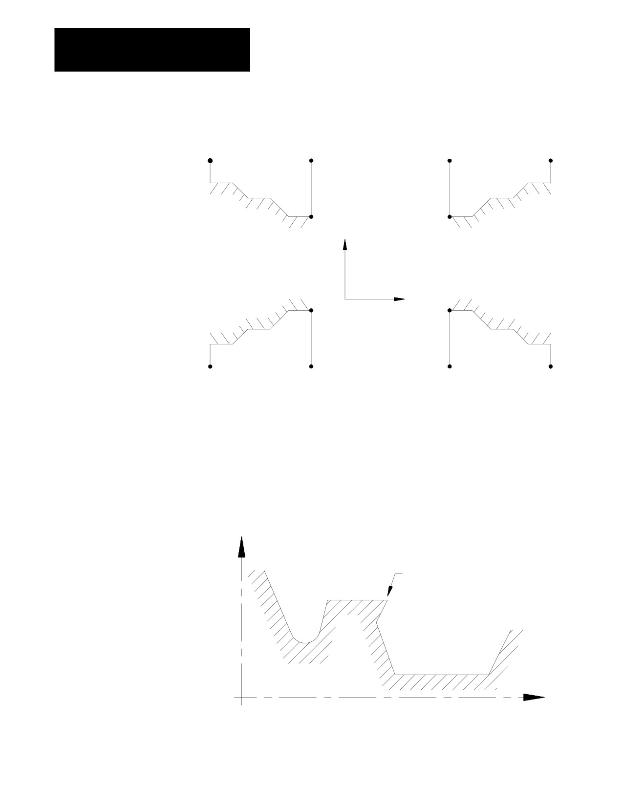
The finish allowance words (U and W) in the G73 block are signed values
dependent on the workpiece contours. Figure 24.4 illustrates this with the
workpiece contour blocks generating the motions from point A to point C.
24-7
Chapter 24
Compounding Turning Routines
Figure 24.4
Effect of Positive and Negative Finish Allowance Parameters
C
A
A
C
B
B
X
U(+), W(+)
U(+). W(-)
Z
B
B
C
A
A
C
U(-), W(+)
U(-), W(-)
The workpiece contour in Figure 24.5 is illegal for the G73 roughing
routine and may not be cut. When this routine is used to cut a contour the
Z axis motion must either continuously increase or continuously decrease.
No reversal is allowed on the Z axis.
Figure 24.5
Illegal Contour for G73 Roughing Routine
X
Z motion is not continuously
decreasing or increasing
Z
24-8
Chapter 24
Compound Turning Routines
G73 Tool Paths, Case 1
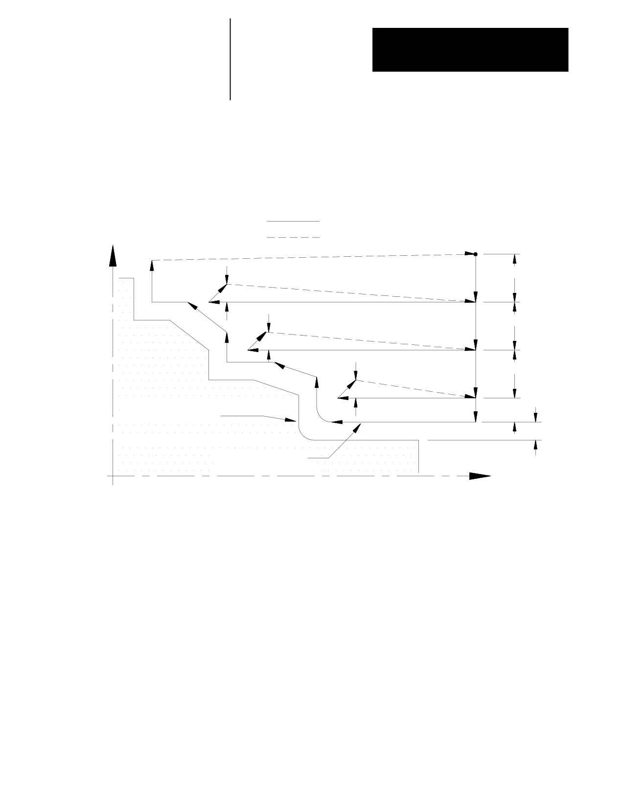
When the control executes a Case 1 G73 contouring path, these tool paths
are generated:
Figure 24.6
Tool Paths for Case 1 G73 Roughing Routine
Cutting feed
(start
Rapid feed
point)
X
D
R
D
R
D
R
Shape defined by workpiece
(I+K)/2
contour blocks
(U+W)/2
Final pass
(Optional)
Z
In Figure 24.6:
1.
The tool is moved from the start point parallel to the X axis, at a
feedrate F, a distance D as programmed in the G73 block.
2.
A rough cut is made parallel to the Z axis, at a feedrate F to a point
that intersects the workpiece contour path, minus the finishing
allowance and final pass allowance (if any).
3.
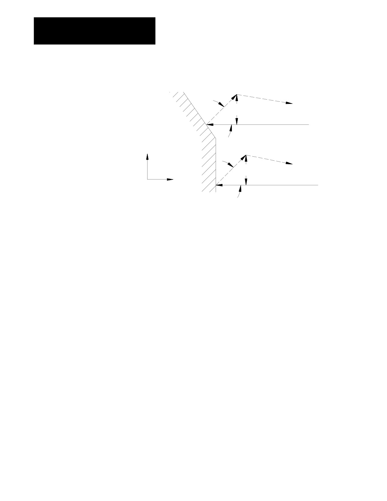
Retract from this point at a 45 degree angle, at a feedrate F, a distance
R measured parallel to the X axis. The R value may be entered as a
parameter in the G73 block. If no value for R is programmed then
the control uses the value for the retract amount set in AMP by the
system installer.
24-9
Chapter 24
Compounding Turning Routines
Figure 24.7
Tool Retraction in Case 1 G73
R
45°
X
R
45°
Z
4.
Rapid traverse back along the X and Z axes to the coordinate that the
last rough cut started from in step 2.
5.
Move parallel to the X axis, at a feedrate F, a distance D as
programmed in the G73 block.
Steps 2 - 5 continue to repeat until the operation is aborted or the rough
contour shape is completed. The rough contour shape is completed when
the thickness of the remaining material to be removed from the workpiece
is equal to the sum of the finishing allowance (U+W)/2 and the final pass
allowance (I+K)/2. If no final pass is to be cut (no I or K in the G73
block), skip to step 7.
6.
The final pass is made at the feedrate programmed in your contour
block including rapid (if the contour does not contain a programmed
feedrate, then it uses the F-word in the G73 block). Only the amount
of material specified with the final pass allowance
(I+K)/2 is cut.
This cut is made parallel to the exact contour of the final workpiece,
it is not a roughing pass. After this cut is complete, the only
remaining material on the workpiece contour is the finish amount (if
any) programmed with U and W.
7.
The control returns the cutting tool, at a rapid feedrate, to the start
point of the cycle.
24-10
Chapter 24
Compound Turning Routines
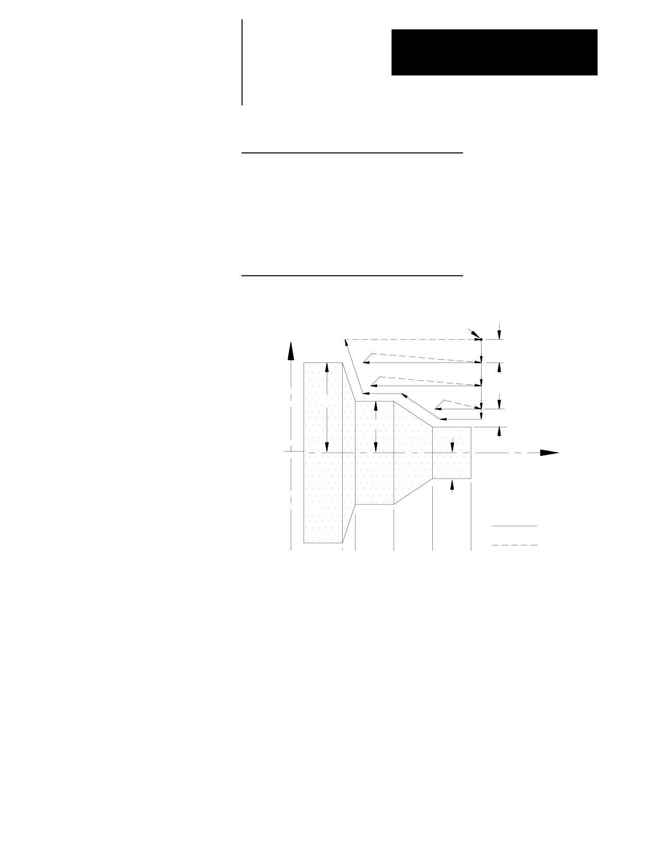
Example 24.2
Case 1 G73 Roughing Routine
N011 G00X80.Z150.;
N012 G73P14Q18U.8W.8I.6K.6D18.R7.F100;
N013 M30;
N014 X20.;
N015 Z110.;
N016 X40.Z80.;
N017 Z50.;
N018 X70.Z40.;
Figure 24.8
Results of Example 24.2
Start Point
X
18
(D)
70
1.4
40
Z
20
Cutting feed
Rapid feed
0
40 50
80
110
140
In Figure 24.8, the final pass over the workpiece does not remove all
material from the final contour. A finishing pass is still required (typically
a G72) to remove the finish amounts U and W.
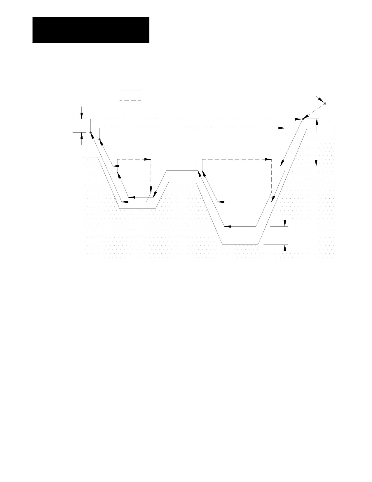
G73 Tool Paths, Case 2
If a pocket or multiple pockets are present in a workpiece contour, it
requires a Case 2 G73 contour turning routine.
For Case 2, the control cuts each pocket separately starting with the pocket
closest to the beginning of the operation. Figure 24.9 shows the tool paths
for a typical multiple pocket contour. The retract path used after each
roughing pass is different than for Case 1 roughing.
24-11
Chapter 24
Compounding Turning Routines
Figure 24.9
Tool Paths for Case 2 G73 Roughing Routine (with pockets)
Cutting feed
Start Point
Rapid feed
R
D
(U+W+I+K)/2
Important: Figure 24.9 does not show the optional final pass being made.
This is for drawing clarity.
In Figure 24.9, after the roughing passes of one pocket have been
completed, the control does not perform a normal retract move out of the
pocket. Instead the control follows the contour out of the pocket and then
proceeds on to the next pocket or finishes the routine.
24-12
Chapter 24
Compound Turning Routines
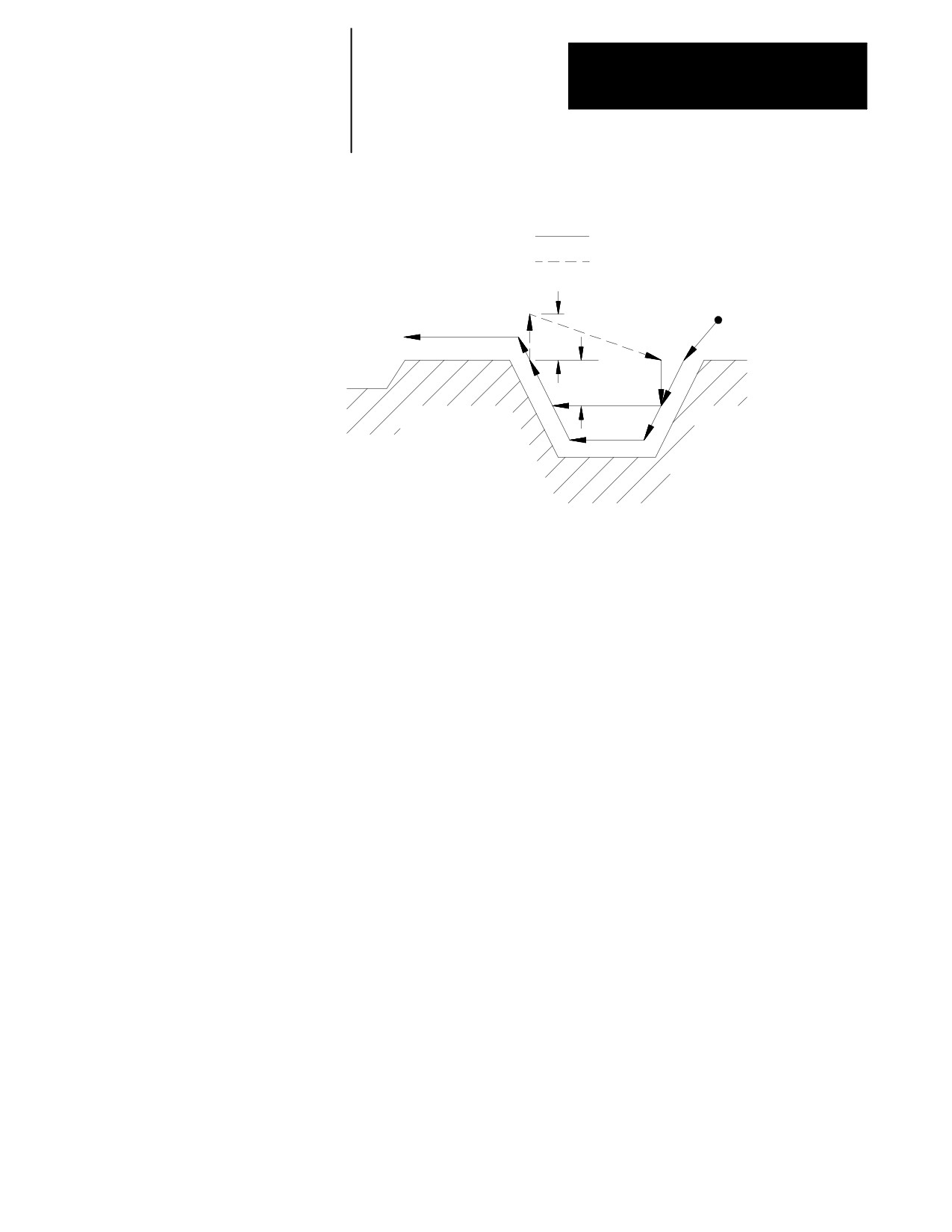
Figure 24.10
Tool Motion in Case 2 G73
Cutting feed
Rapid feed
Start point
8
6
R
5
1
7
2
4
D
3
8
8
8
In Figure 24.10, these tool paths are made:
1.
The tool is moved from the start point to first contour point at
feedrate F. This move must generate motion in both the X and Z
axes.
2.
The control generates a rough cut towards the spindle centerline,
parallel to the workpiece contour, and offset by the finish allowance
amount and the final pass amount (if any). This rough cut continues
until the X axis value has decreased an amount D as programmed in
the G73 block.
3.
A rough cut is made parallel to the Z axis, at a feedrate F, to a point
that intersects with the workpiece contour path minus the finish
allowance and final pass allowance (if any).
4.
A rough cut is made away from the spindle’s centerline, parallel to
the workpiece contour, and offset by the finish allowance amount and
the final pass amount (if any). This rough cut continues, at a feedrate
F, until the X axis value has increased an amount D as programmed
in the G73 block (or until the last contour point is reached).
5.
The tool is retracted from this point, on the X axis only, a distance R
as programmed in the G73 block (or the default distance R set in
AMP) at a feedrate F (see Figure 24.10)
6.
A rapid traverse is made back along the X and Z axes to the Z
coordinate that the last rough cut started from (in step 3) and an X
coordinate that is D distance above the X coordinate of the last
rough cut.
24-13
Chapter 24
Compounding Turning Routines
7.
A rough cut is made at feedrate F, into the workpiece parallel to the X
axis to the X coordinate of the last rough cut.
Steps 2 - 7 continue to repeat until the operation is aborted or the rough
contour shape is completed. The rough contour shape is completed when
the thickness of the remaining material to be removed from the contour is
equal to the sum of the finish allowance (U+W)/2 and the final pass
allowance (I+K)/2. If no final pass is to be cut, skip to step 9.
If a final pass is programmed in the G73 block (I or K values in the G73
block) it is not executed until all of the workpiece pockets have been
completely roughed out.
8.
The final pass is made at the feedrate programmed in your contour
block including rapid moves (if no feedrate is programmed in the
contour blocks, the control uses the F-word in the G73 block). Only
the amount of material specified with the final pass allowance
(I+K)/2 is cut. This cut is made parallel to the exact contour of the
final workpiece, it is not a roughing pass. After this cut is complete,
the only remaining material on the workpiece contour is the finish
amount (if any) as programmed with U and W.
9.
The control returns the cutting tool, at a rapid feedrate, to the start
point of the cycle.
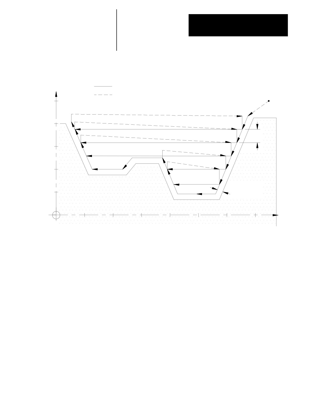
Example 24.3
Case 2 G73 Roughing Routine
N010 G00X100.Z150.;
N011 G73P13Q20U.8W.8I.6K.6D10.R7.F100.;
N012 M30;
N013 X85.Z135.;
N014 X15.Z115.;
N015 Z82.;
N016 X45.Z72.;
N017 Z55.;
N018 X35.Z50.;
N019 Z22.;
N020 X80.Z7.;
24-14
Chapter 24
Compound Turning Routines
Figure 24.11
Results of Example 24.3
X
Cutting feed
Rapid feed
Start Point
100
80
10
60
40
(I+K+U+W)/2
20
1.4
Z
20
40
60
80
100
120
140
24.2
The G74 rough facing routine is used to rough out the contour of a
workpiece by making repetitive cuts parallel to the X axis. A final pass
Rough Facing Routine (G74)
may be made with this routine to cut parallel to the final contour of the
workpiece. At the completion of this routine a finish allowance may also
be left on the workpiece to be removed later by a G72 finishing routine.
This routine may be used in conjunction with Tool Tip Radius
Compensation (TTRC). If TTRC is active when the routine is executed the
tool radius is taken into consideration on each consecutive pass.
24-15
Chapter 24
Compounding Turning Routines
Figure 24.12
Stock Removal in G74 Rough Facing
Tool paths determined automatically
Start point
X
Shape after roughing
and final pass
Workpiece finished
Finishing allowance
shape
Z
The G74 block has a P and Q parameter that call the sequence numbers
(N-words) of the first and last blocks defining the final contour to be cut
into the workpiece. This set of blocks may be located anywhere after the
calling block (even after an end of program command), as long as the
calling block is in the same program as the set of contour defining blocks.
This means that contour blocks can not be called from a subprogram or a
macro unless the calling block is in that subprogram or macro.
The control handles two different cases of the G74 routine and
automatically recognizes them and adapts the tool path accordingly.
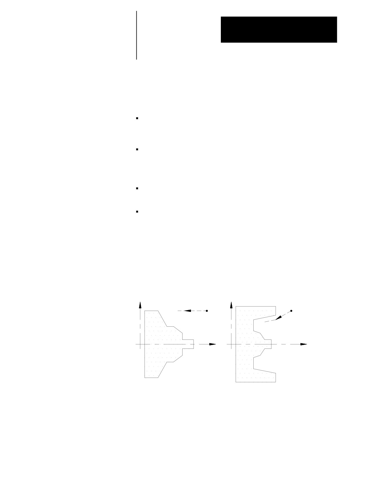
Case 1:
A Case 1 G74 rough facing routine is defined when the workpiece contour
has no pockets. The following constraints must be met in order to
successfully perform a Case 1 rough facing routine:
The first block of the contour program must command motion in only
the Z axis. No X axis motion is permitted in the first block of the
contour program.
The contour either continuously increases or continuously decreases in
both the X and Z axis except for the first block of the contour program.
The first contour point in the contour blocks must be closer to the
spindle centerline than the last contour point.
24-16
Chapter 24
Compound Turning Routines
Case 2:
A Case 2 G74 rough facing routine is defined when a workpiece contour
contains a pocket. The following constraints must be met in order to
successfully perform a Case 2 rough facing routine:
The first block of the contour program must contain motion in both the
X and Z axis (the move from the start point to the first contour point
must have motion in both axes).
The workpiece contour may increase or decrease along the Z axis after
the first contour block. The workpiece contour must either continuously
increase or continuously decrease along the X axis after the first contour
block.
The first contour point of the contour blocks must be farther away (or at
least equidistant) from the spindle face than the last contour point
The first and last contour blocks must define beginning and ending sides
to the contour. The first programmed endpoint must be farther away
from the spindle face than the second programmed endpoint. The last
programmed endpoint must be farther away from the spindle face than
the next to last programmed endpoint.
Figure 24.13
Workpiece Finish Contour Case 1 and Case 2 (G74)
Case 1
Case 2
X
X
Start Point
Start
point
Z
Z
The G74 block is programmed with the following format:
G74P__Q__U__W__I__K__D__R__F__S__T__;
24-17
Chapter 24
Compounding Turning Routines
Where :
Is :
P__
the sequence number (N-word) of the first block in the set of contour blocks that
define the final contour.
Q__
the sequence number (N-word) of the last block in the set of contour blocks that
define the final contour.
U
W
determine the finishing allowance that is left on the part when the routine is
completed. This finish allowance is typically removed later in the program when
a G72 finishing routine block is executed. The actual value of the finish
allowance is equal to the average of the U and W parameters (U+W)/2. It is not
necessary to enter both of these parameters in the calling block. If only one is
entered, the control uses half of the entered parameter value as the finish
amount. The finish allowance is optional and does not need to be programmed.
See Figure 24.15 to determine the sign of U and W. U and W are always
programmed as incremental values.
Important: This manual makes the assumption that W and U are assigned
in AMP as the incremental axis names that correspond to the Z and X axes
respectively.
Important: The value assigned to U is affected by radius/diameter mode
(G08/G09). W is not affected by radius diameter mode. If programming in
diameter mode the value of the finish allowance is really ((U/2)+W)/2.
I
K
determine the amount of stock to be removed on the final pass of the routine.
The actual amount of material removed on this final pass is equal to the average
of the I and K parameters (I+K)/2. It is not necessary to enter both of these
parameters in the calling block. If only one is entered the control uses half of the
entered parameter value. The final pass is optional and does not need to be
programmed. It is not a roughing pass and it does not remove the finish
allowance. A final pass cuts tool paths that are parallel to the workpiece finish
shape.
Important: This manual makes the assumption that I and K are assigned in
AMP as the integrand axis names that correspond to the X and Z axes
respectively.
Important: The value assigned to I is always an incremental, radius value
regardless of the current mode (radius/diameter). K is always an incremental
value and is not affected by radius/diameter mode.
Important: The system installer has the option of forcing a final pass to be
made by setting the proper AMP parameter. If this is the case the control cuts
the final pass regardless of whether I or K is programmed. When I and K are not
programmed and the system installer has forced a final pass to be made, the
control assumes I and K to be zero.
D__
the depth of cut for each pass except the final pass. No sign needs to be entered
for this parameter. The depth of cut for the final pass is determined with the I and
K parameters. D is always an incremental value regardless of the current mode.
Important: It is possible to override the programmed depth of cut (D) using
an AMP parameter. The override setting is made in increments of 1% ranging
from 0-255%. See documentation prepared by the system installer for details.
The system installer may also determine a maximum allowable value of D in
AMP. If the D value programmed is larger than the maximum allowed in AMP,
the control overrides the programmed value and use the AMP assigned
maximum value.
24-18
Chapter 24
Compound Turning Routines
Where :
Is :
R__
used to program the retract amount made after each rough facing pass. This
retract amount is an incremental, radius value measured parallel to the Z axis.
Case 1 operations retract at a 45 degree angle to the Z axis and Case 2
operations retract parallel to the Z axis. This does not affect the programmed
value of R, as R is always measured parallel to Z. If no value for R is
programmed then the control uses a value for the retract amount set in AMP by
the system installer.
F:
Active feedrate during the routine only (see chapter 17)
S:
Spindle speed during the routine only (see chapter 16)
T:
Tool number and tool offset to be used during the routine only (see chapter 19)
Important: Any F-, S-, or T-words that are in the set of contour blocks are
ignored when the routine is executed. If programmed in the G74 block
these words replace any previously active modal F-, S-, or T-words for the
remainder of G74 routine operation only. When the G74 routine is
completed the previously active modal F-, S-, and T-words are reactivated.
Figure 24.14
Parameters for G74 Rough Facing
(I+K)/2
D
Start point
X
Shape after roughing
Shape after roughing
and final pass
R
Workpiece finished
(U+W)/2
shape
Z
24-19
Chapter 24
Compounding Turning Routines
In Figure 24.14, the contour blocks for this routine must define all motions
that would cut the workpiece finished shape. The first block of the contour
blocks must be the tool path from the start point to the point where the
initial roughing pass begins. The first block of the contour blocks may not
be a rapid move (G00).
Important: The blocks preceding the G74 roughing block must have
positioned the cutting tool to a location above the part (start point in the
above figure) from which it can safely move to begin the roughing passes.
If cutting a Case 1 contour, the first of the contour blocks must command Z
axis motion only (no X axis motion). If cutting a Case 2 contour, the first
of the contour blocks must command both an X and Z axis motion.
The G74 roughing routine activates the Tool Tip Radius Compensation
(TTRC) function regardless of whether it was active prior to the roughing
routine. If TTRC was not active, the roughing routine uses the tool tip
radius data of the previously programmed T-word. At the end of the
roughing routine, TTRC is cancelled unless it was active prior to the
roughing routine.
In Example 24.4, the workpiece contour blocks are blocks N11 - N14.
Example 24.4
Typical G74 Block Followed by Blocks Defining Final Contour
N005 G74 P11 Q14 U.2 W.2 D1.2 F10. S210;
N010 M30;
N011 Z25;
N012 X55 Z40;
N013 X40 Z65;
N014 X30 Z75;
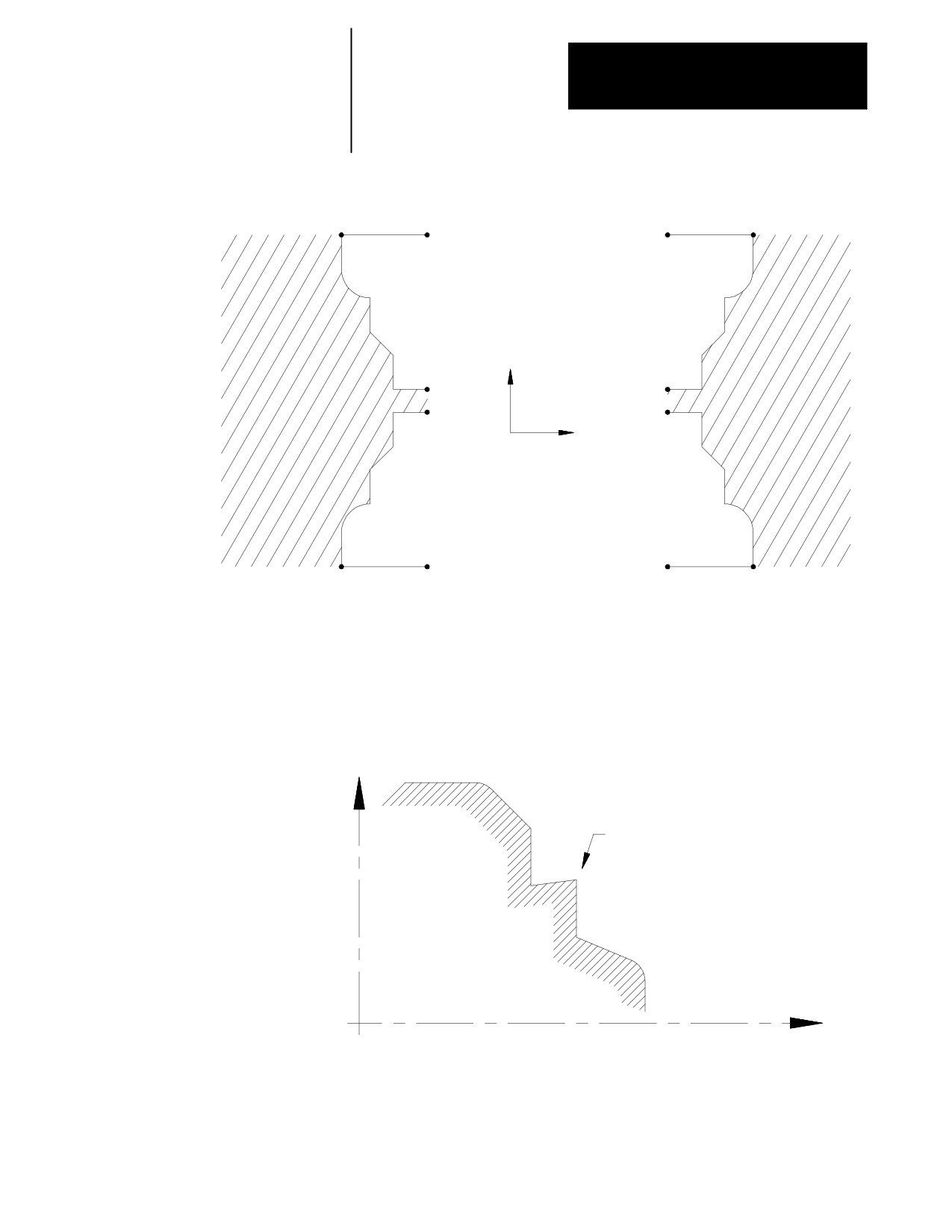
The finish allowance words (U and W) in the G74 block are a signed value
dependant on the workpiece contours. Figure 24.15 illustrates this with the
workpiece contour blocks generating the motions from point A to C.
24-20
Chapter 24
Compound Turning Routines
Figure 24.15
Effect of Positive and Negative Finish Allowance Parameters
A
A
B
B
U(+), W(+)
U(+), W(-)
X
C
C
C
C
Z
U(-), W(+)
U(-), W(-)
B
B
A
A
In Figure 24.16, the workpiece contour is illegal for the G74 roughing
routine and may not be cut. When this cycle is used to cut a contour the X
axis motion must either constantly increase or constantly decrease. No
reversal is allowed on the X axis.
Figure 24.16
Illegal Contour for G74 Rough Facing
X
X motion is not continuously
decreasing or increasing
Z
24-21
Chapter 24
Compounding Turning Routines
G74 Tool Paths, Case 1
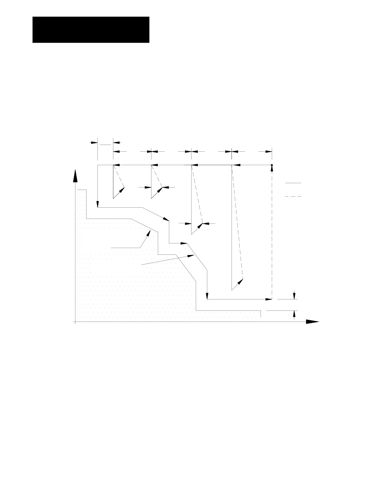
When the control executes a Case 1 G74 rough facing routine the
following tool paths are generated:
Figure 24.17
Tool Paths for Case 1 G74 Rough Facing
(I+K)
2
D
D
D
D
start
X
point
Cutting feed
R
Rapid feed
R
Shape defined by
workpiece contour
blocks
Final Pass
(optional)
(U+W)/2
Z
In Figure 24.17:
1. The tool is moved from the start point parallel to the Z axis, at a
feedrate F, a distance D as programmed in the G73 block.
2. A rough cut is made parallel to the X axis, at a feedrate F to a point
that intersects the workpiece contour path, minus the finishing
allowance and final pass allowance (if any).
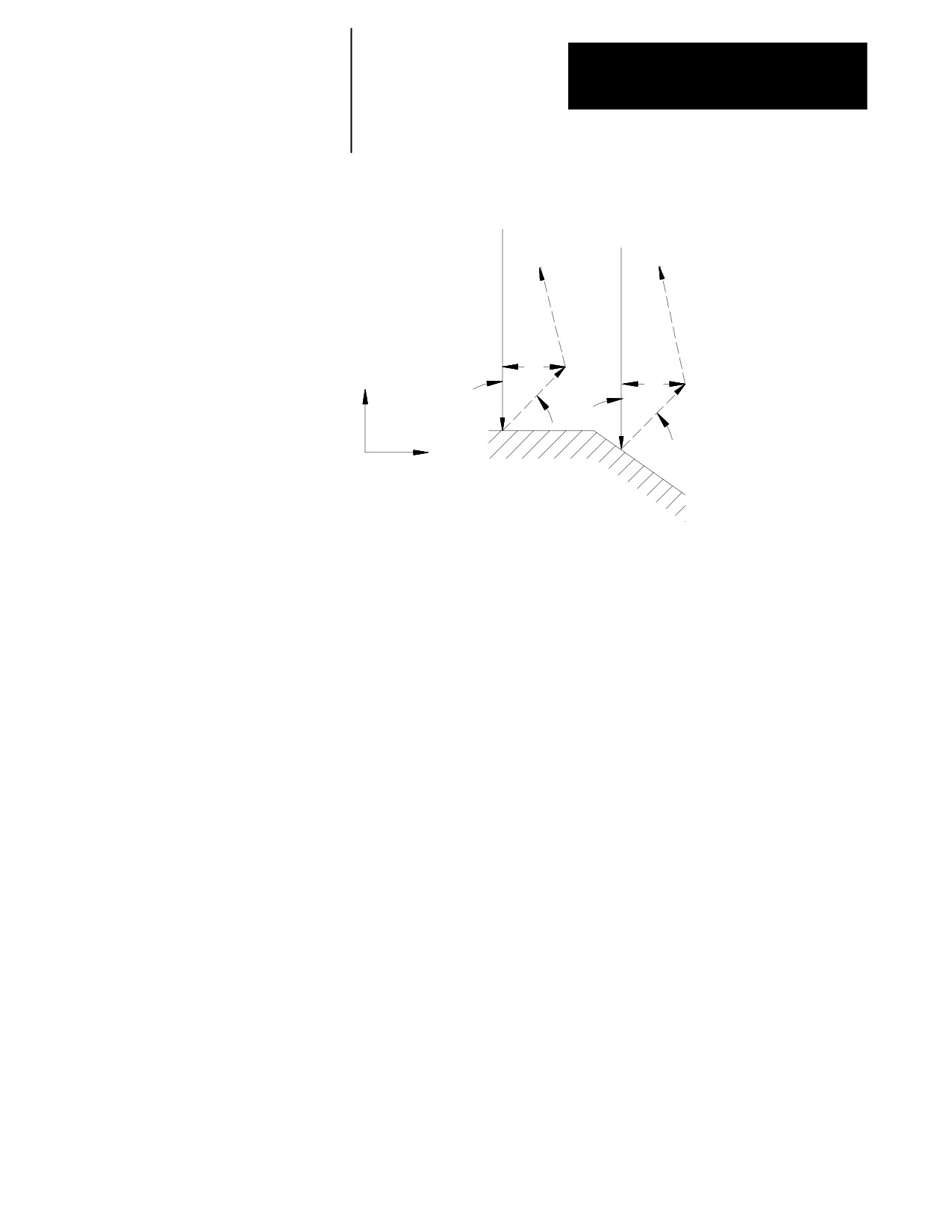
3. Retract from this point at a 45 degree angle, at a feedrate F, a distance
R measured parallel to the Z axis. The R value may be entered as a
parameter in the G74 block. If no value for R is programmed then the
control uses the value for the retract amount set in AMP by the
system installer.
24-22
Chapter 24
Compound Turning Routines
Figure 24.18
Tool Retraction in Case 1 G74
R
X
R
45°
45°
Z
4. Rapid traverse back along the X and Z axes to the coordinate that the
last rough cut started from (in step 2).
5. Move parallel to the Z axis, at a feedrate F, a distance D as
programmed in the G74 block.
Steps 2 - 5 continue to repeat until the operation is aborted or the rough
contour shape is completed. The rough contour shape is completed when
the thickness of the remaining material to be removed from the workpiece
is equal to the sum of the finishing allowance (U+W)/2 and the final pass
allowance (I+K)/2. If no final pass is to be made skip to step 7.
6. The final pass is made at the feedrate programmed in your contour
block including any rapid moves (if no feedrate is programmed in the
contour blocks the control uses the F-word programmed in the G74
block). Only the amount of material specified with the final pass
allowance (I+K)/2 is cut. This cut is made parallel to the exact
contour of the final workpiece, it is not a roughing pass. After this
cut is complete, the only remaining material on the workpiece contour
is the finish amount (if any) programmed with U and W.
7. The control returns the cutting tool, at a rapid feedrate, to the start
point of the cycle.
24-23
Chapter 24
Compounding Turning Routines
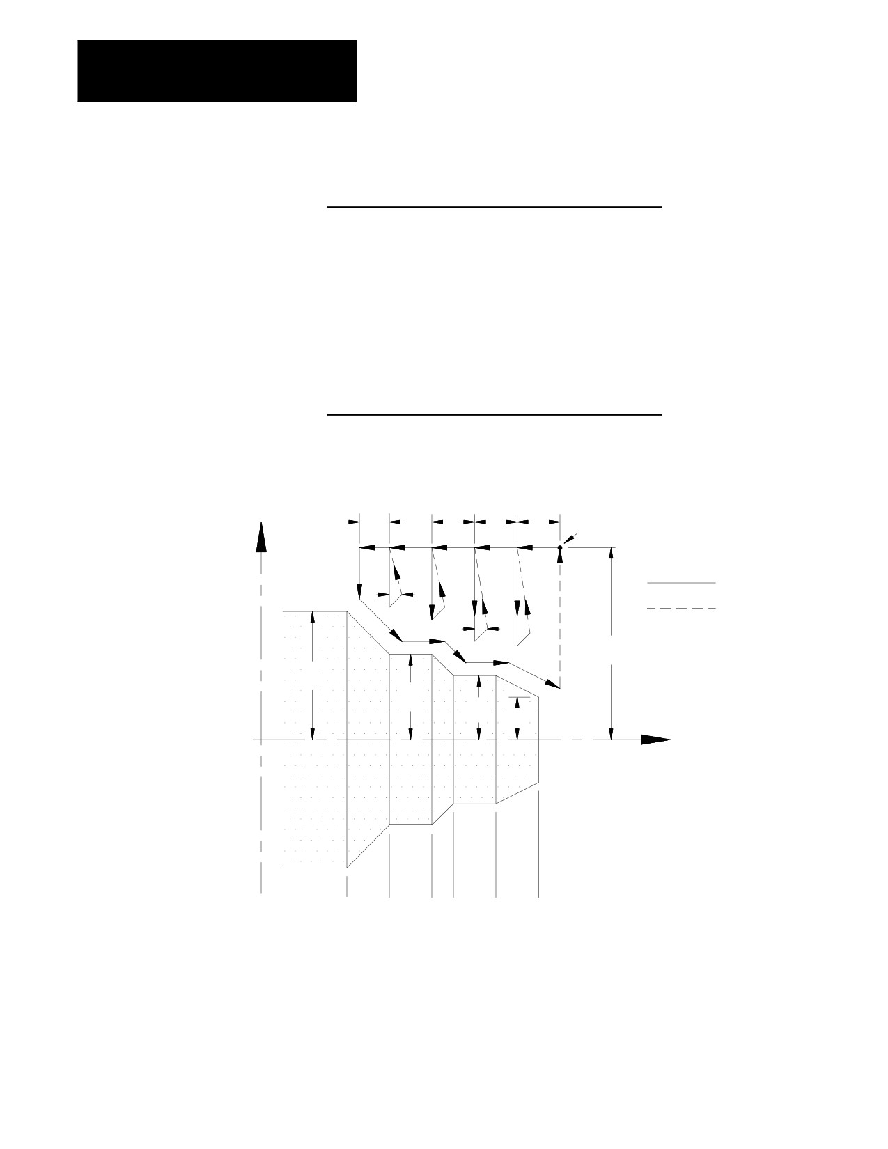
Example 24.5
Case 1 G74 Rough Facing Routine
N011 G00X80.Z130.;
N012 G74P14Q19U6.W6.I10.K10.D10.R8.F10.S60;
N013 M30;
N014 Z40.;
N015 X60.;
N016 X40.Z60.;
N017 Z80.;
N018 X30.Z90.;
N019 Z110.;
N020 X20.Z130.;
Figure 24.19
Results of Example 24.5
(D)
(D)
(D)
(start
(K)
X
20
20
20
point)
10
Cutting feed
8
Rapid feed
8
80
60
40
30
20
Z
0
40
60
80 90
110
130
In Figure 24.19, the final pass over the workpieces does not remove all
material from the final contour. A finishing pass is still required (typically
a G72) to remove the finish amounts U and W.
24-24
Chapter 24
Compound Turning Routines
G74 Tool Paths, Case 2
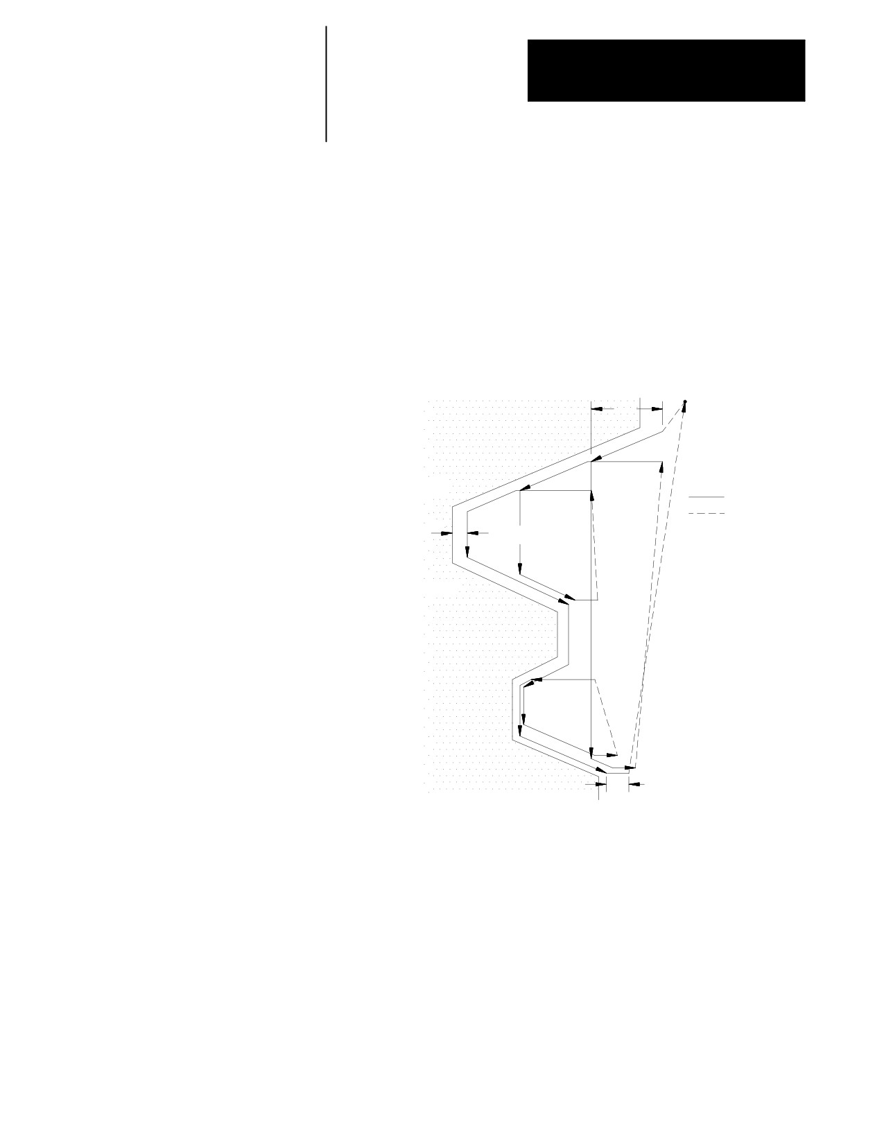
If a pocket or multiple pockets are present in a workpiece face, it requires a
Case 2 G74 rough facing routine.
For Case 2, the control cuts each pocket separately, starting with the pocket
closest to the beginning of the operation. Figure 24.20 shows the tool
paths for a typical multiple pocket contour. The retract path used after
each roughing pass is different than for Case 1 rough facing.
Figure 24.20
Tool Paths for Case 2 G74 Rough Facing Routine (with pockets)
Start Point
D
Cutting feed
Rapid feed
(U+W+I+K)/2
R
Important: Figure 24.20 does not show the optional final pass being
made. This is for drawing clarity.
In Figure 24.20, after the roughing passes of one pocket have been
completed, the control does not perform a normal retract move out of the
pocket. Instead the control follows the part contour out of the pocket and
then proceeds on to the next pocket or finishes the routine.
24-25
Chapter 24
Compounding Turning Routines
Figure 24.21
Tool Motion in Case 2 G74
Start point
1
2
Cutting feed
8
7
Rapid feed
D
8
3
6
R
8
4
5
8
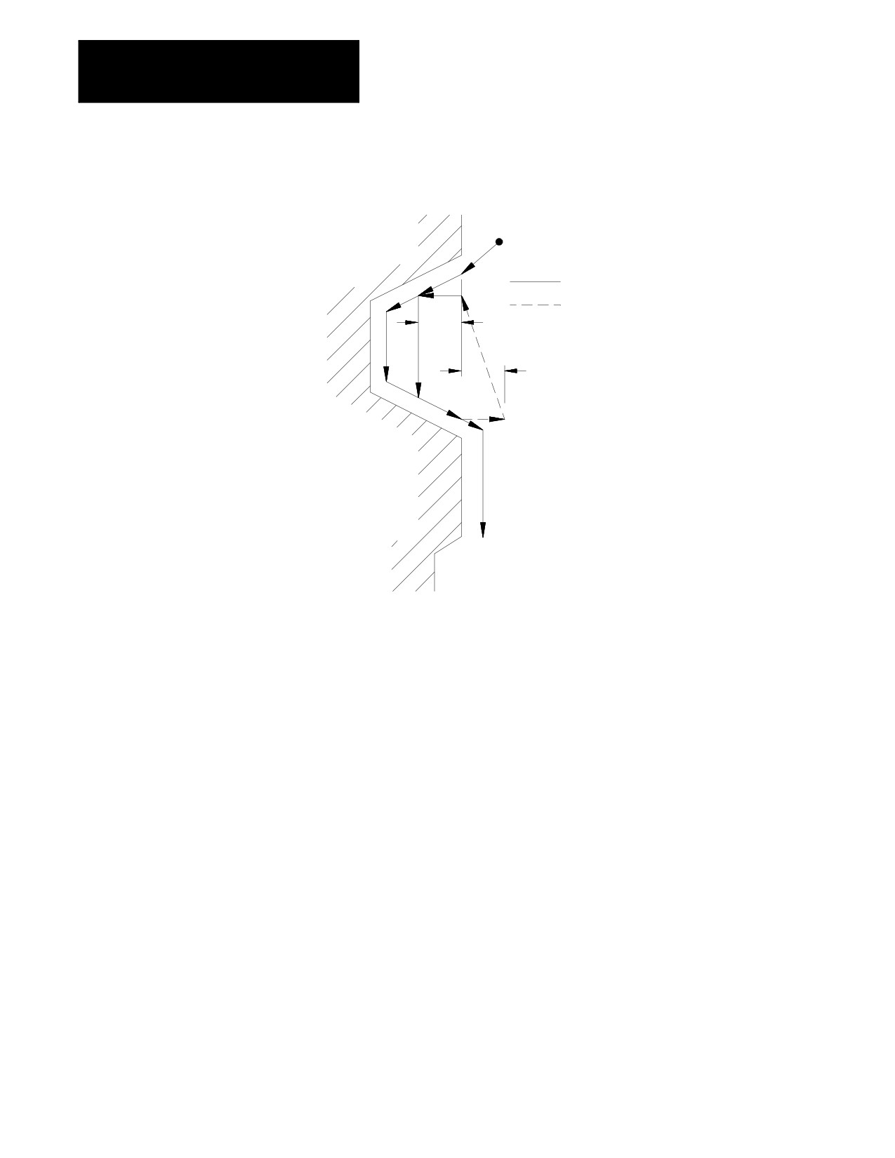
In Figure 24.21, these tool paths are made:
1. The tool is moved from the start point to the first contour point at
feedrate F. This move must generate motion in both the X and Z
axes.
2. The control generates a rough cut towards the spindle face, parallel to
the workpiece contour, and offset by the finish allowance amount and
the final pass amount (if any). This rough cut continues until the Z
axis value has decreased an amount D as programmed in the G74
block.
3. A rough cut is made parallel to the X axis, at a feedrate F, to a point
that intersects with the workpiece contour path minus the finish
allowance and final pass allowance (if any).
4. A rough cut is made away form the spindle face, parallel to the
workpiece contour, and offset by the finish allowance amount and the
final pass amount (if any). This rough cut continues, at a feedrate F,
until the Z axis value has increased an amount D as programmed in
the G74 block.
5. The tool is retracted from this point, on the Z axis only, a distance R
as programmed in the G74 block (or the default distance R set in
AMP) at a feedrate F (see Figure 24.21).
24-26
Chapter 24
Compound Turning Routines
6. A rapid traverse is made back along the X and Z axes to the X
coordinate that the last rough cut started from (in step 3) and a Z
coordinate that is D distance above the Z coordinate of the last rough
cut.
7. A rough cut is made at feedrate F, into the workpiece parallel to the Z
axis to the Z coordinate of the last rough cut.
Steps 2 - 7 continue to repeat until the operation is aborted or the contour
shape is completed. The contour shape is completed when the thickness of
the material remaining to be removed from the contour is equal to the sum
of the finish allowance (U+W)/2 and the final pass allowance (I+K)/2. If
no final pass is to be cut, skip to step 9.
If a final pass is programmed in the G74 block (I or K values in the G74
block) it is not executed until all of the workpiece pockets have been
completely roughed out.
8. The final pass is made at the feedrate programmed in your contour
block including any rapid moves (if no feedrate is programmed in the
contour blocks, the control uses the F-word programmed in the G74
block). Only the amount of material specified with the final pass
allowance (I+K)/2 is cut. This cut is made parallel to the exact
contour of the final workpiece, it is not a roughing pass. After this
cut is complete, the only material remaining on the workpiece contour
is the finish amount (if any) as programmed with U and W.
9. The control returns the cutting tool, at a rapid feedrate, to the start
point of the cycle.
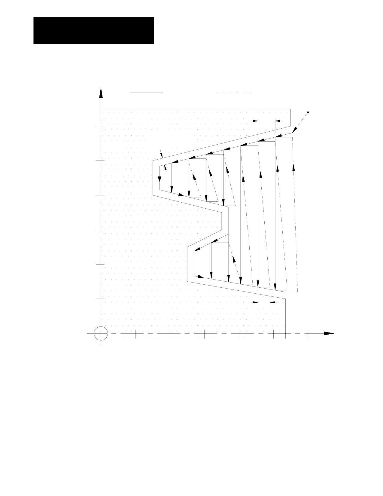
Example 24.6
Case 2 G74 Rough Facing Routine
N011 G00X128.Z120.;
N012 G74P14Q21U.6W.6I.8K.8D10.R7.F10.S60;
N013 M30;
N014 X120.Z110.;
N015 X100.Z30.;
N016 X80.;
N017 X70.Z70.;
N018 X60.;
N019 X50.Z50.;
N020 X30.;
N021 X20.Z107.;
24-27
Chapter 24
Compounding Turning Routines
Figure 24.22
Results of Example 24.6
X
Cutting feed
Rapid feed
Start point
10
120
A
(I+K+U+W)/2
1.4
100
80
60
40
20
7
Z
20
40
60
80
100
120
24-28
Chapter 24
Compound Turning Routines
24.3
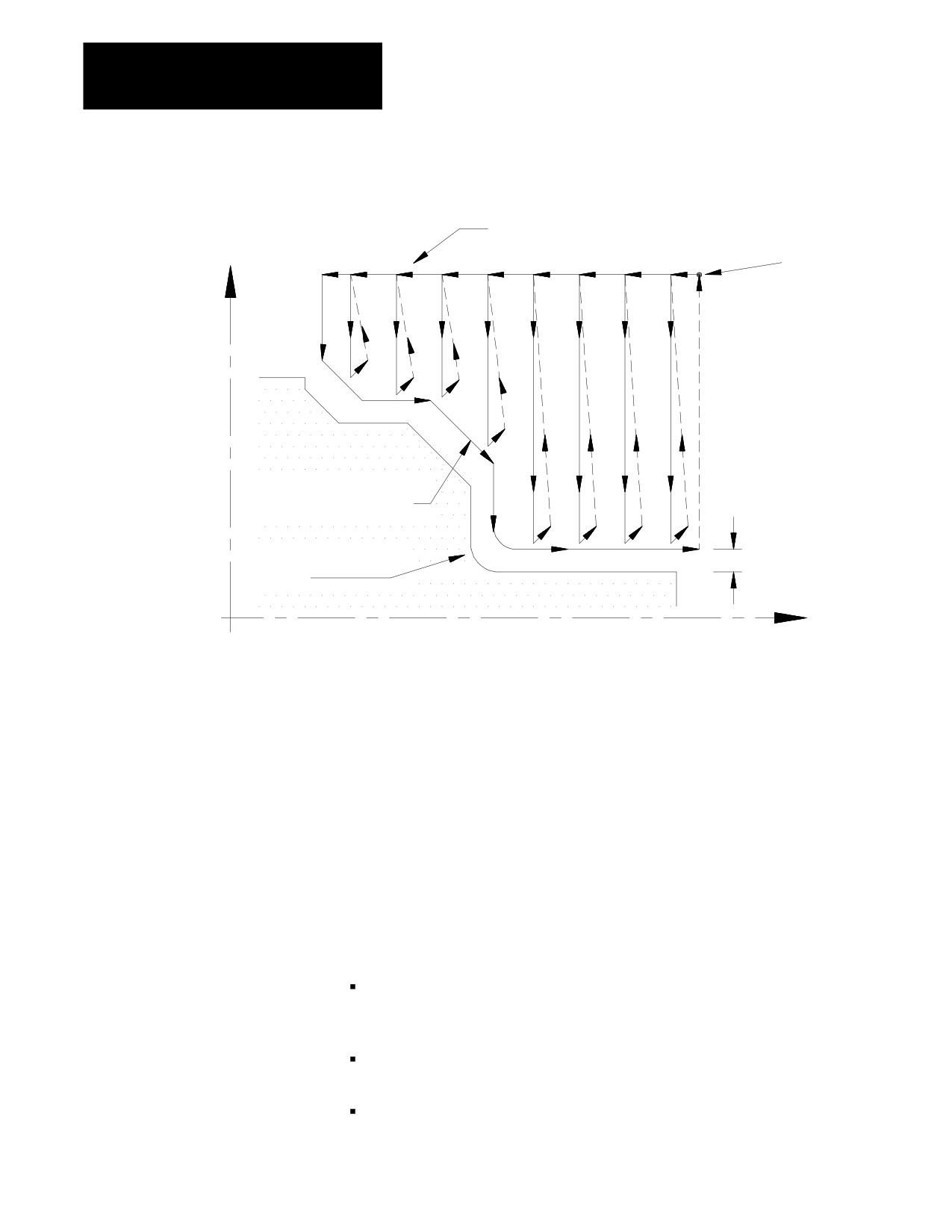
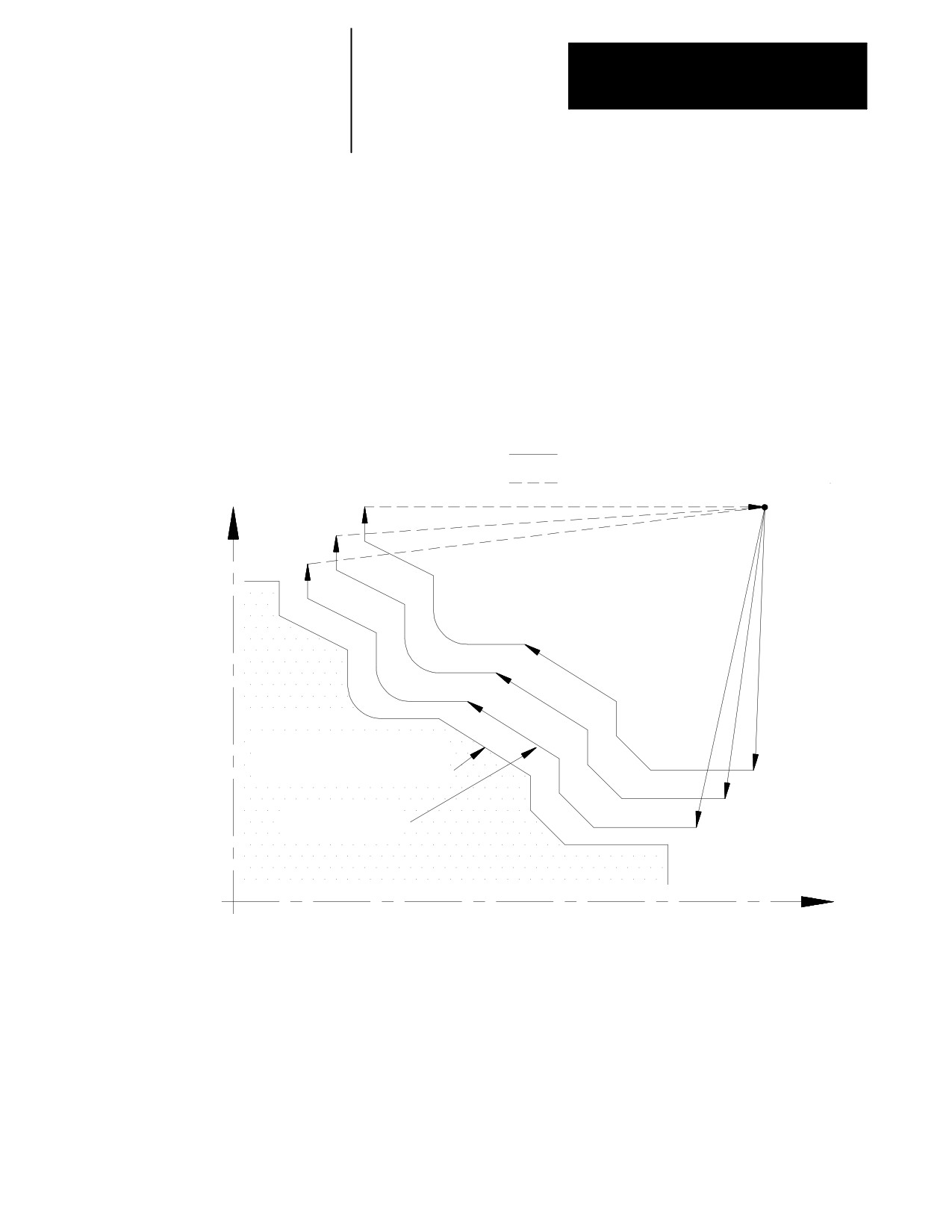
In the G75 casting/forging roughing routine (also called pattern repeating
routine), the control generates multiple cuts, each parallel to the workpiece
Casting/Forging Roughing
final shape. Each cut is offset from the other an amount determined by the
Routine (G75)
I, K and D parameters.
Through this process, a shape similar to the finished contour is obtained
when the routine is completed. At the completion of this routine a finish
allowance is usually left on the workpiece to be removed later by a G72
finishing routine.
Figure 24.23
Pattern Repeating Routine
Cutting feed
Rapid feed
X
(start point)
Note: Tool paths not to scale.
Shape defined by
workpiece contour blocks
Finishing pass
Z
The calling block references the sequence numbers (N-words) of the first
and last blocks of the contour blocks defining the final contour of the
workpiece. This set of blocks may be located anywhere after the calling
block (even after an end of program command), as long as the calling
block is in the same program as the set of contour defining blocks.
Contour blocks cannot be in a subprogram or a macro unless the calling
block is in that subprogram or macro.
24-29
Chapter 24
Compounding Turning Routines
The G75 block is programmed with this format:
G75 P__
Q__ I__ K__ U__ W__ D__ F__ S__ T__;
Where :
Is :
P__
The sequence number of the first block in the set of contour blocks that defines the
finished workpiece shape.
Q__
The sequence number of the last block in the set of contour blocks that defines the
finished workpiece shape.
U
W
Finish allowance. These parameters determine the finishing allowance that is left on
the part when the routine is completed. This finish allowance is typically removed
later in the program when a G72 finishing routine block is executed. The actual value
of the finish allowance is equal to the average of the U and W parameters ((U+W)/2).
It is not necessary to enter both of these parameters in the calling block. If only one
is entered, the control uses half of the entered parameter value as the finish amount.
The finish allowance is optional and does not need to be programmed. See
Figure 24.25 to determine the sign of U and W. U and W are always programmed as
incremental values.
Important: This manual makes the assumption that W and U are assigned in
AMP as the incremental axis names that correspond to the Z and X axes
respectively.
Important: The value assigned to U is affected by radius/diameter mode
(G08/G09). W is not affected by radius diameter mode. If programming in diameter
mode the value of the finish allowance is really ((U/2)+W)/2.
I
K
These parameters determine the incremental distance between the first and last pass
of the routine. This distance is equal to the average of the I and K parameters
((I+K)/2). The location of the last pass is determined by the contour blocks and the
finish amount ((U+W)/2), if any is programmed. I and K must be programmed. They
are neither positive nor negative.
Important: This total incremental distance should be less than one tool radius if
cutter compensation is on when this cycle is executed.
Important: This manual makes the assumption that K and I are assigned in
AMP as the integrand axis names that correspond to the Z and X axes respectively.
Important: The values assigned to I and K are always an incremental, radius
value regardless of the current mode (radius/diameter or absolute/incremental).
D__
Number of passes. The integer value entered with this parameter determines how
many passes are made to reach the final pass. The depth of each pass is
determined by dividing (I+K)/2 by D-1. The value entered with D must be an integer.
F__
Active feedrate during the routine only (see chapter 17)
S__
Spindle speed during the routine only (see chapter 16)
T__
Tool number and tool offset to be used during the routine only (see chapter 19)
Important: Any F-, S-, or T-words that are in the set of contour blocks are
ignored when the routine is executed. If these words are to be changed
from their current value, it is necessary to program an F-, S-, or T-word in
the G75 block. If programmed in the G75 block these words replace any
previously active modal F-, S-, or T-words for the remainder of G75
routine operation only. When the G75 routine is completed the previously
active modal F-, S-, and T-words are reactivated.
24-30
Chapter 24
Compound Turning Routines
Figure 24.24
Pattern Repeating Routine Parameters
Cutting feed
Rapid feed
X
(start point)
Note: Tool paths not to scale.
Shape defined by
workpiece contour blocks
(I+K)/2
Finishing pass
(U+W)/2
Z
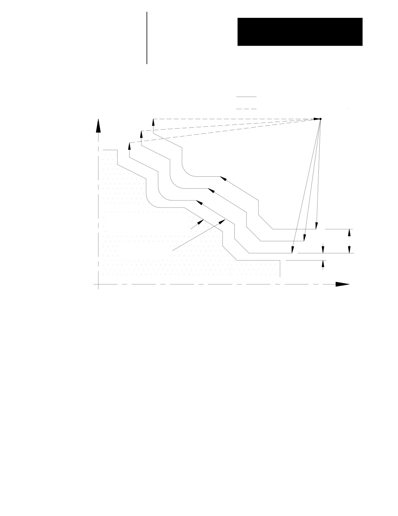
In Figure 24.24, the contour blocks for this routine must define all motions
that would cut the workpiece finished shape and the tool path that connects
the start point of the routine to the first block of the workpiece finished
shape. The first block of the contour blocks must be the tool path from the
start point to the first block of the workpiece finished shape. It is assumed
that some other blocks have positioned the cutting tool to a position above
the part (start point in the above figure).
The arc and pocket in the example above get smaller and smaller as the
passes get farther away from the final contour. If you specify passes very
far from the final contour, the cutting tool can be too large to cut the
resulting arc or pocket. When this occurs the control generates the error
message “INVALID CYCLE PROFILE”. Resolve this problem by making
the distance from the final pass to the first pass smaller. This cycle was not
designed to remove large amounts of material. Its intended design is to
perform cleanup passes on castings or forgings. If you must remove large
amounts of material you should use one of the roughing/facing routines
discussed earlier in this chapter.
24-31
Chapter 24
Compounding Turning Routines
Prevent this invalid cycle profile error by keeping the right portion of the
following equation less than the radius of any arcs in your cycle profile.
R² p(I+U)2 + (K+W)2
+ (tool radius)
The same basic equation can apply to other contours. If the length of a
block in the contour is less than the right portion of the above equation,
you can get an “INVALID CYCLE PROFILE” error depending on your
part contour. For contours with pockets, the width of the pocket must be at
least twice the value of the right hand portion of the above equation. In
general this error is a result of removing metal too far from the original
part profile (I, K, U, or W too large) and reducing this distance typically
resolves the error condition.
The workpiece contour blocks can be at any location within the same
program containing the G75 block (even after an end of program block).
They can not be resident in a subprogram or macro that is called by the
program containing the G75 block. Contour blocks can be either circular
or linear blocks. Any F-, S-, or T-words that are programmed in this set of
contour blocks are ignored when they are executed as workpiece contour
blocks in the G75 mode.
In Example 24.7, the workpiece contour blocks are blocks N11 - N14.
Example 24.7
Typical G75 Block Followed By Blocks Defining Final Contour
N005 G75P11Q14I2.W2.D3.F10.S210;
N010 M30.;
N011 X24.;
N012 X55.Z40.;
N013 X65.Z35.;
N014 X70.Z5.;
The control generates multiple passes each offset from the other by an
amount equal to the total material to be removed (I+K/2) divided by the
number of passes (D) minus 1. The tool paths repeat until (D) tool paths
have been made across the part. Each tool path is shifted sequentially by
the distance obtained in this division to generate roughing paths. If a
finishing allowance (U, W) was programmed in the block, it is left uncut.
After the completion of the roughing routine, the cutting tool returns to the
routines starting point.
24-32
Chapter 24
Compound Turning Routines
The G75 routine can be programmed while the tool tip radius
compensation mode (G41 or G42) is active. If tool tip radius
compensation is active prior to the G75 block it remains active throughout
the execution of the routine.
The G75 roughing routine activates the Tool Tip Radius Compensation
(TTRC) function regardless of whether it was active prior to the roughing
routine. If TTRC was active, the roughing routine uses the previously
programmed T-word to compensate for the tool tip radius. At the end of
the roughing routine, TTRC is cancelled unless it was active prior to the
roughing routine.
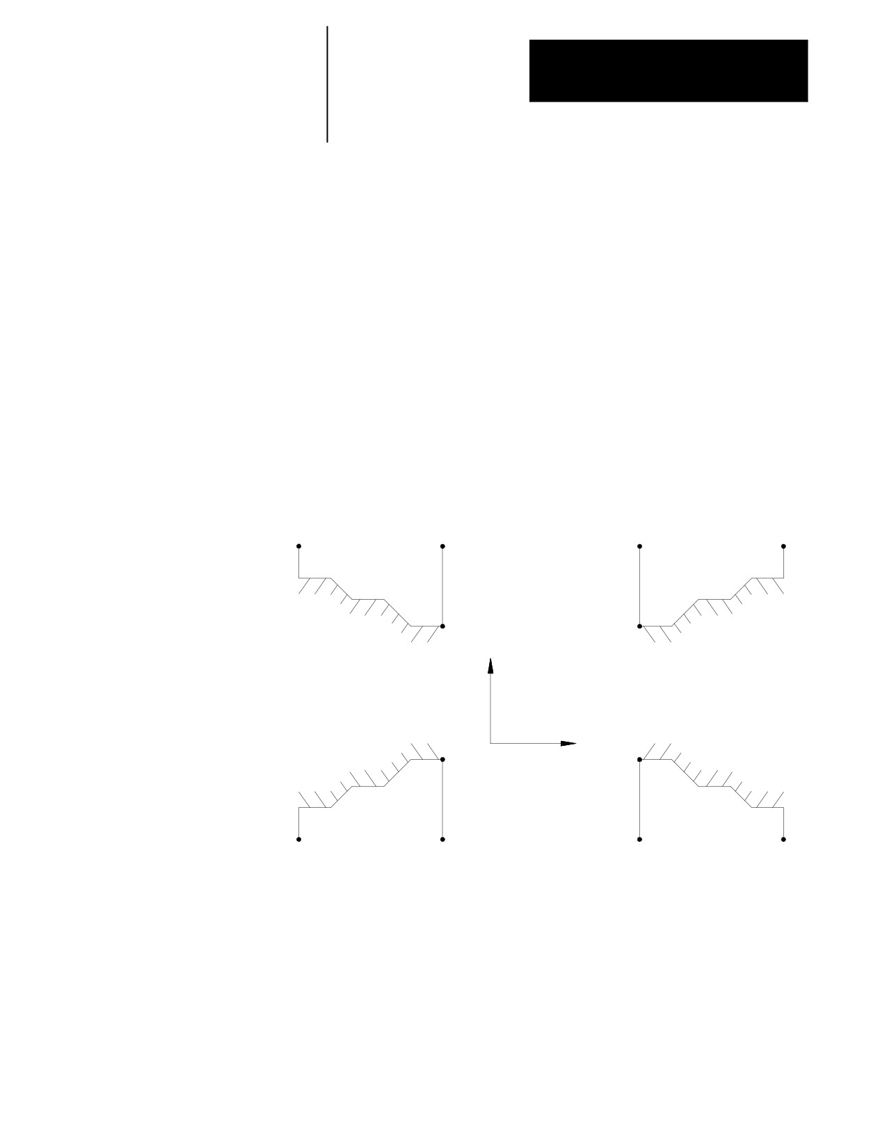
The finish allowance words (U and W) in the G75 block are signed values
dependant on the workpiece contours. Figure 24.25 illustrates this with the
workpiece contour program generating the blocks from point A to C.
Figure 24.25
Effect of Positive and Negative Finish Allowance Parameters
C
A
A
C
B
B
X
U(+), W(+)
U(+). W(-)
Z
B
B
C
A
A
C
U(-), W(+)
U(-), W(-)
The control generates multiple passes each offset from the other by an
amount equal to the total material to be removed (I and K) divided by the
number of passes (D) minus 1. These tool paths repeat until (D) tool paths
have been made across the part. At completion of the last path the tool
returns to the start point of the routine.
24-33
Chapter 24
Compounding Turning Routines
When the G75 routine is executed in single block mode, the execution of
the routine stops after each complete iteration of the routine (a total of D
iterations are made).
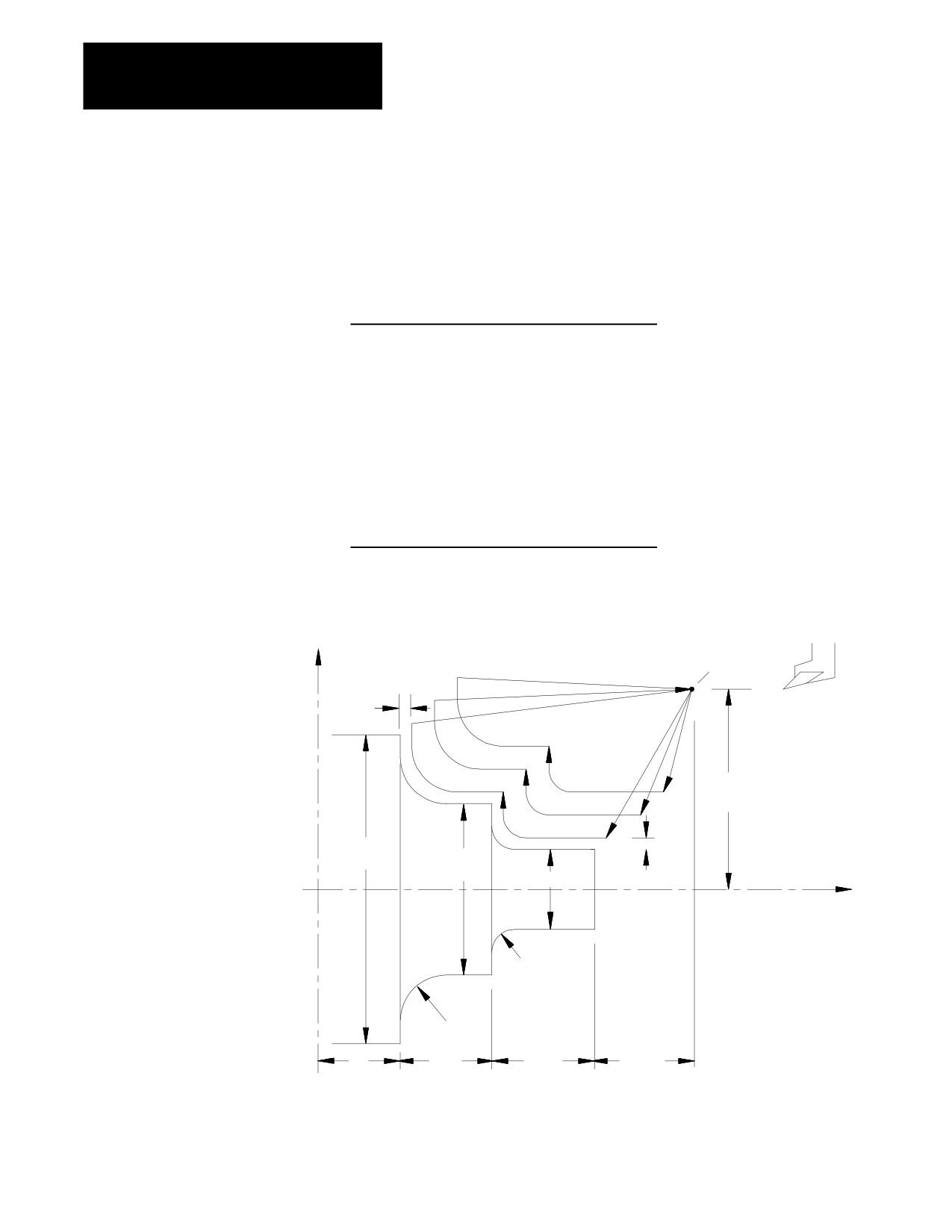
Example 24.8
G75 Casting/Forging Roughing Routine
N11 G00X100.Z175.;
N12 G75P14Q20I8.K12.U5.W5.D3F.1S100;
N13 M30;
N14 G00 X20.Z125;
N15 G01 Z85.;
N16 G02X30.Z75.R10.;
N17 G01X50.;
N18 Z55.;
N19 G02X60.Z35.R20.;
N20 G01X80.;
Figure 24.26
Results of G75 Casting/Forging Roughing Routine Example
Note: Tool paths not to
start
X
point
scale.
5
100
5
160
100
40
Z
R10
R20
35
40
50
50
24-34

Chapter 24
Compound Turning Routines
24.4
The G72 finish routine is normally executed after the completion of a
contouring routine (G73, G74 or G75). With the G73, G74, and G75
O.D. and I.D. Finishing
routines a finish allowance is left on the workpiece if a U- and/or K-word
Routine (G72)
is specified in the routine. The G72 routine is used to remove this finish
allowance and cut the workpiece to within the specified tolerance of the
actual workpiece finished shape.
The calling block references sequence numbers of the first and last blocks
of the contour blocks defining the final contour of the workpiece. This set
of blocks may be located anywhere after the calling block (even after an
end of program command), as long as the calling block is in the same
program as the set of contour defining blocks. This means that contour
blocks can not be called from a subprogram or a macro unless the calling
block is in that subprogram or macro. This routine actually executes the
set of contour defining blocks as entered in the program.
The G72 finishing routine is usually performed at a lower feedrate to
produce the desired finish results that are not necessary using the other
rough contouring routines for rapid removal of material.
The program format for this finishing routine is indicated below:
G72 P__ Q__;
Where :
Is :
P__
The sequence number of the first block in the set of contour blocks that defines
the finished workpiece shape.
Q__
The sequence number of the last block in the set of contour blocks that defines
the finished workpiece shape.
In the G72 finishing routine, the contour of the finished workpiece can be
described by a set of linear and/or circular blocks bounded by the sequence
numbers specified with parameters P and Q. It is assumed that some other
blocks have positioned the cutting tool to some position above the part.
This position should be the start point of the workpiece contour blocks.
The workpiece contour blocks may be at any location within the same
program containing the G72 block (even after an end of program M02 or
M30). They may not be resident in a subprogram or macro that is called
by the program containing the G72 block.
The control recognizes F-, S-, or T-words programmed in this set of
contour blocks and uses these values for the routines execution. These
values are not ignored as in the G73, G74, and G75 routines (F-words are
used in the G73, G74, and G75 routines).
24-35
Chapter 24
Compounding Turning Routines
In Example 24.9, the workpiece contour blocks are blocks N11 - N14.
Example 24.9
Typical G72 Block Followed by Blocks Defining Final Contour
N005 G72P11Q14;
N010 M30.;
N011 X24.;
N012 X55.Z40.;
N013 X65.Z35.;
N014 X70.Z5.;
The G72 routine can be programmed while the tool tip radius
compensation mode (G41 or G42) is active. If tool tip radius
compensation is active prior to the G72 block, it remains active
throughout the execution of this routine.
END OF CHAPTER
24-36