9/Series CNC Lathe. Operation and Programming Manual - page 18
Chapter 21
Tool Tip Radius Compensation (TTRC)
Function
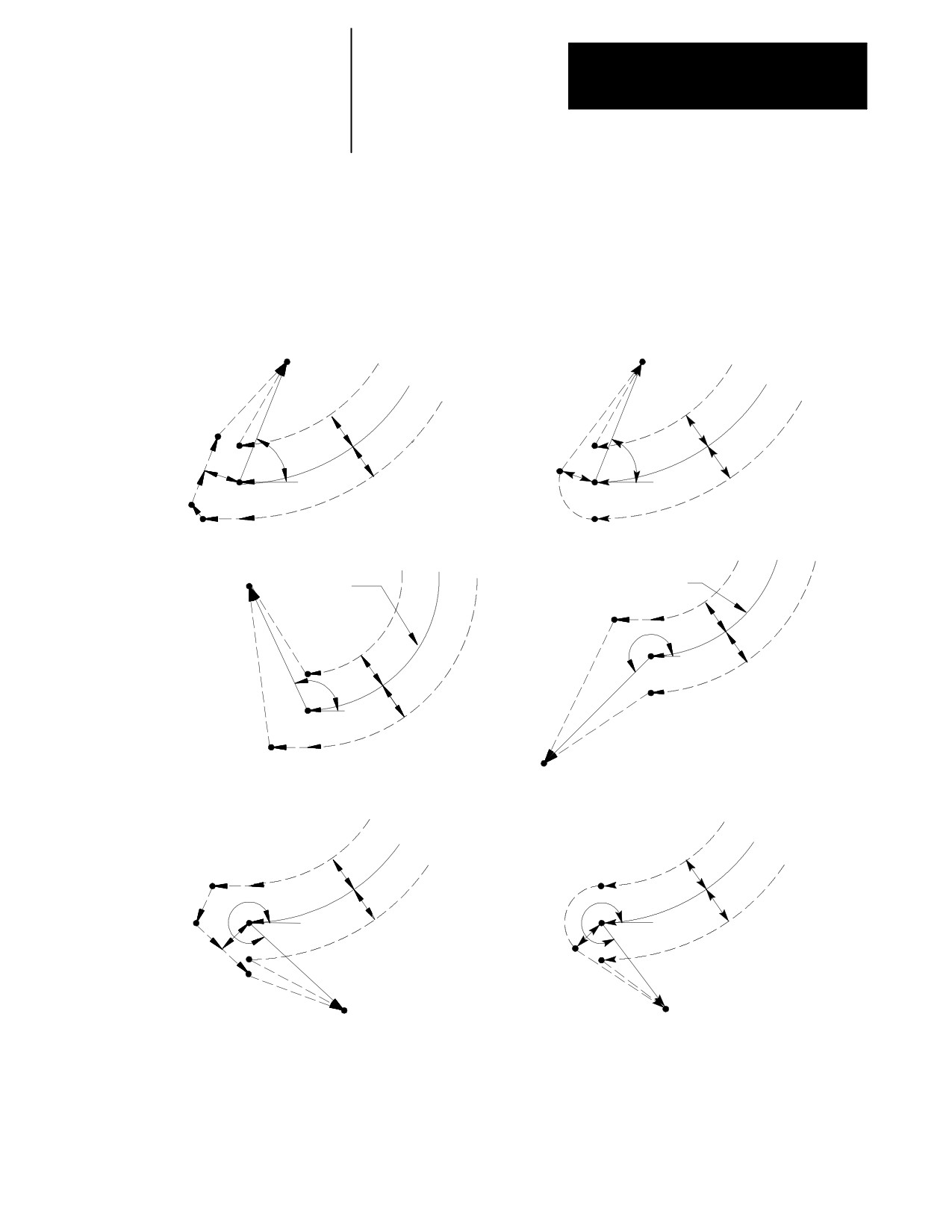
If the last programmed move is circular (an arc), the tool is positioned at
right angles to a tangent line drawn from the end-point of that circular
move.
Figure 21.21
Tool Path for Exit Move Arc-to-Straight Line
G39 (Linear Generarated Blocks)
G39.1 (Circular Generated Block)
0
£q£90
0
£q£90
End-point
End-point
G42
G42
Programmed path
Programmed path
G41
G41
r
r
r
r
q
r
q
r
r
r
r
r
G42
G41
90
£q£180
G42
G41
180
£q£270
End-point
Programmed
Path
Programmed path
r
r
q
r
r
q
r
r
End-point
G39 (Linear Generated Block)
G39.1 (Circular Generated Block)
270
£q£360
G42
270
£q£360
G42
Programmed path
Programmed path
G41
G41
r
r
r
q
r
r
q
r
r
r
r
End-point
End-point
12117-I
21-27
Chapter 21
Tool Tip Radius Compensation (TTRC)
Function
Figure 21.20 and Figure 21.21 assume that the number of blocks that do
not contain axes motion in the currently selected plane, following G40
before the exit move takes place, do not exceed an amount selected in
AMP by your system installer. If the number of non-motion blocks
following G40 exceeds the limit, the control generates its own exit move.
This may often cause overcutting of the part, since this move is a linear
path directly back to the programmed tool path.
You can modify the path that the tool takes for an exit move by including
an I- and/or K-word in the exit move. Only the I- or K-words that
represent values in the current plane are programmed in the block
containing the exit move. I and K correspond to the X and Z axis
respectively.
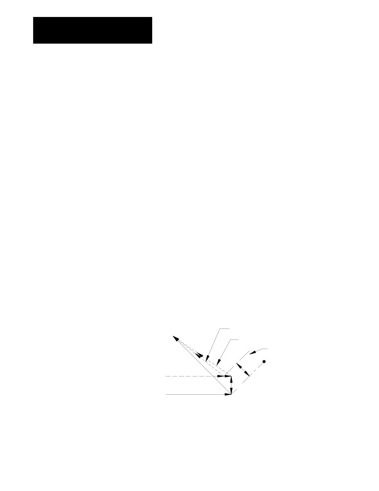
The I- and K-words in the exit move block define a vector that the control
uses to redefine the end-point of the previously compensated move.
The vector defined by the I- and/or K-words is along a line drawn from the
end-point of the programmed path through a point programmed with the I-
or K-words. The I- and/or K-words must be in the currently defined plane.
The point defined by I and K is always one incremental distance from the
end-point of the last move measured parallel to the X and Z axis.
A new vector is then defined parallel to the vector defined by the I- and/or
K-word and offset from this vector in the direction and amount of the
currently active offset (G41 or G42). The intersection of this new vector
with the current compensated tool path defines a point which is the new
end-point of the last programmed compensation move.
Figure 21.22
Exit Move Defined By An I, K Vector
Compensated path using I, K vector
Compensated path if no I, K in G40 block
Intercept line
r
I, K
Compensated path
r
Programmed path
Figure 21.22 is the exception. The change in length of the compensated
path is more than one radius of the tool. In this case, this offset is limited
to one radius of the tool. The direction of the offset is towards the point of
intersection of the I and/or K vector and the current compensated tool path.
21-28
Chapter 21
Tool Tip Radius Compensation (TTRC)
Function
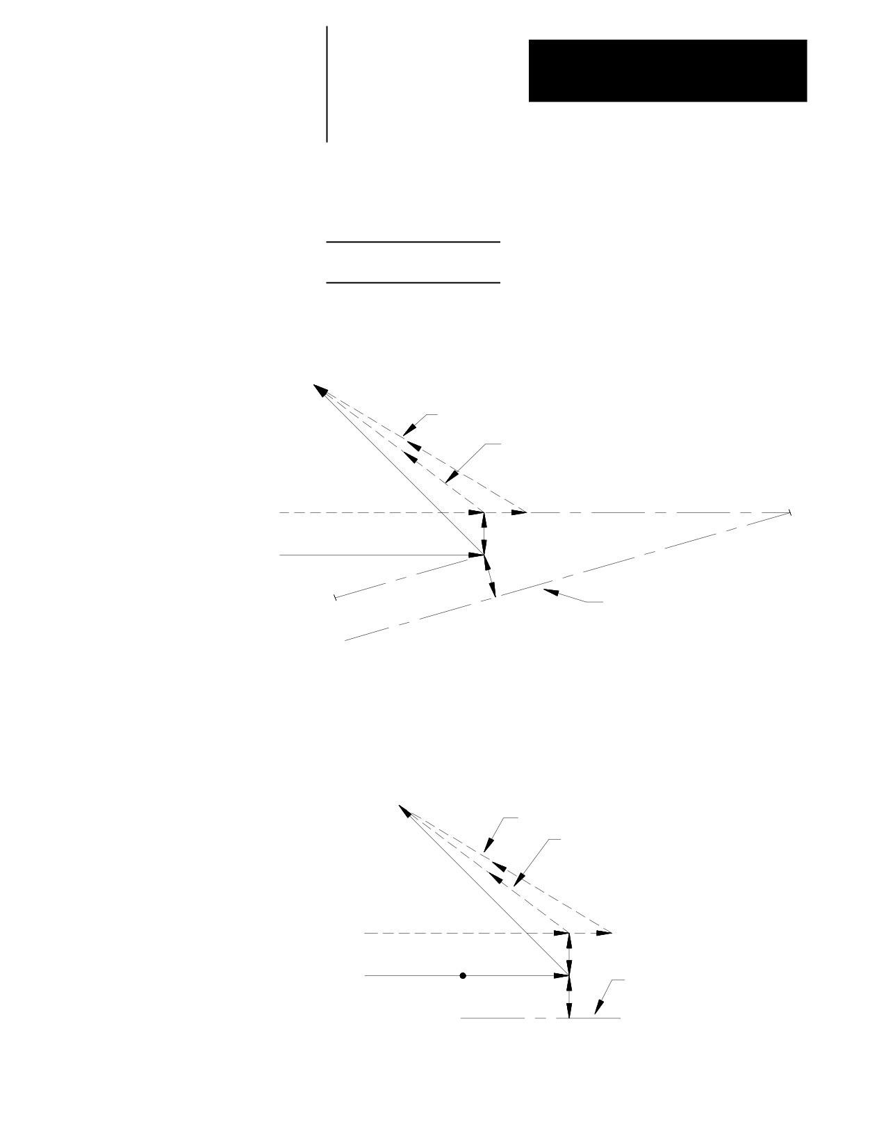
Example 21.10
Exit Move Defined By An I, K Vector But Limited To Tool Radius
Assume T1 radius is 3.
N10 Z10.G41T1;
N11 X10.Z2.I3K-10.G40;
Figure 21.23
Results of Example 21.10
Compensated path using I, K vector
Compensated path if no I, K in G40 block
N11
Compensated path
r
r
Programmed path
N10
r
I, K
Intercept line
If the vector defined by I and/or K is parallel to the programmed tool path,
the resulting exit move is offset in the opposite direction of the I, K vector
by one tool radius.
Figure 21.24
Exit Move When I, K Vector is Parallel to Programmed Tool Path.
Compensated path using I, K vector
Compensated path if no I, K in G40 block
Compensated path
r
r
Programmed path
Intercept line
I, K
r
Important: If one I and/or K value is programmed without the second one,
the value of the second I- and/or K-word defaults to 0.
21-29
Chapter 21
Tool Tip Radius Compensation (TTRC)
Function
21.5
Except for entry and exit moves, the basic tool path generated during
TTRC is the same for types A and B TTRC. Whether tool left or tool right
Tool Path During TTRC
is specified, the path taken is a function of the angle between tool paths
(G41 or G42) and the radius of the cutting tool.
Important: If at any time during the execution of TTRC blocks a block
reset is performed, the TTRC function re-initializes and the next move acts
as an entry move as described in an earlier section.
Important: When cutting arcs with TTRC active, the control may need to
adjust the programmed feedrate to maintain cutting speed. See chapter 18
for details on feedrates during TTRC.
The control generates extra motion blocks to keep the cutting tool in
tolerance of the desired tool path. This becomes necessary when the
intersection of tool paths is an outside tool path (as defined in section 22.1)
that has an angle as follows:
between 0°and 90°during TTRC left (G41)
between 270°and 360°during TTRC right (G42)
21-30
Chapter 21
Tool Tip Radius Compensation (TTRC)
Function
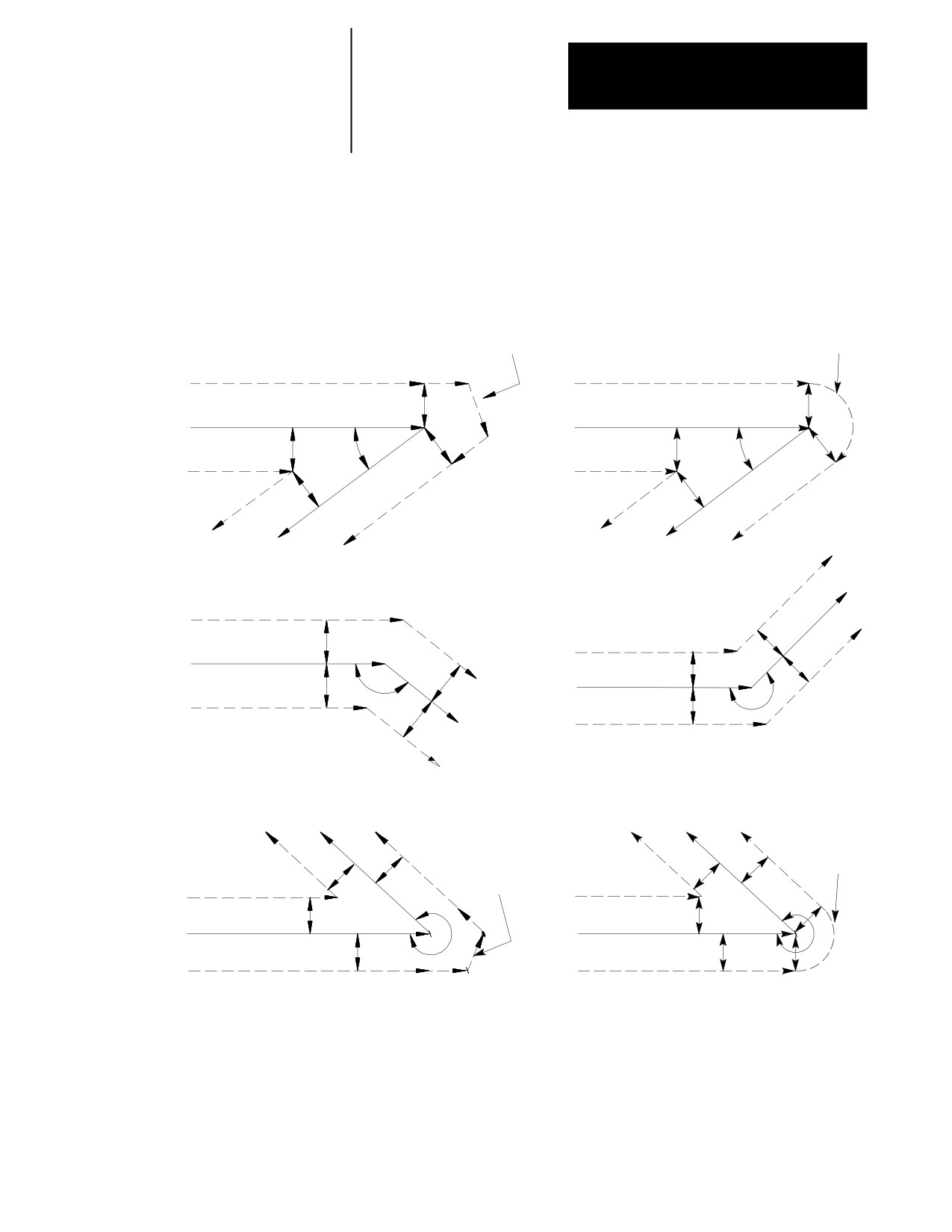
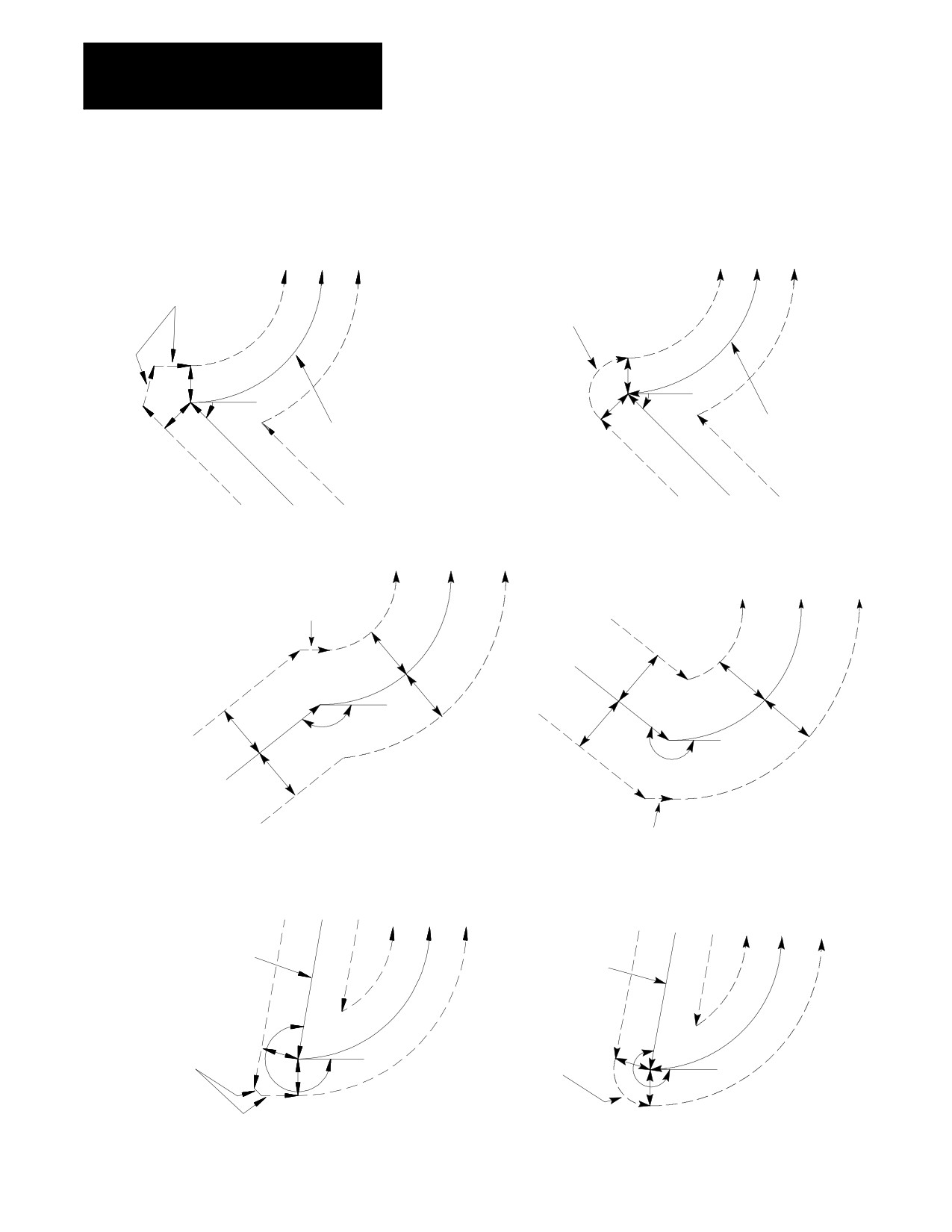
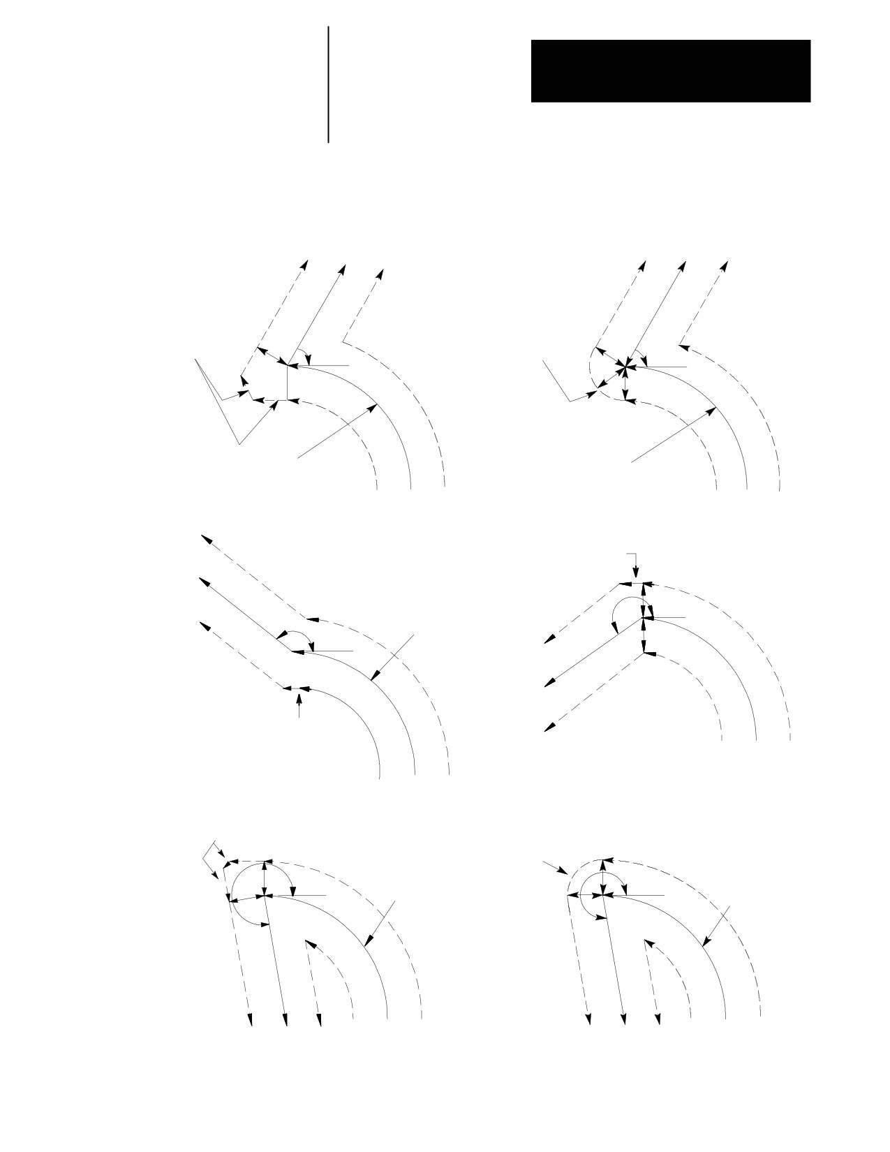
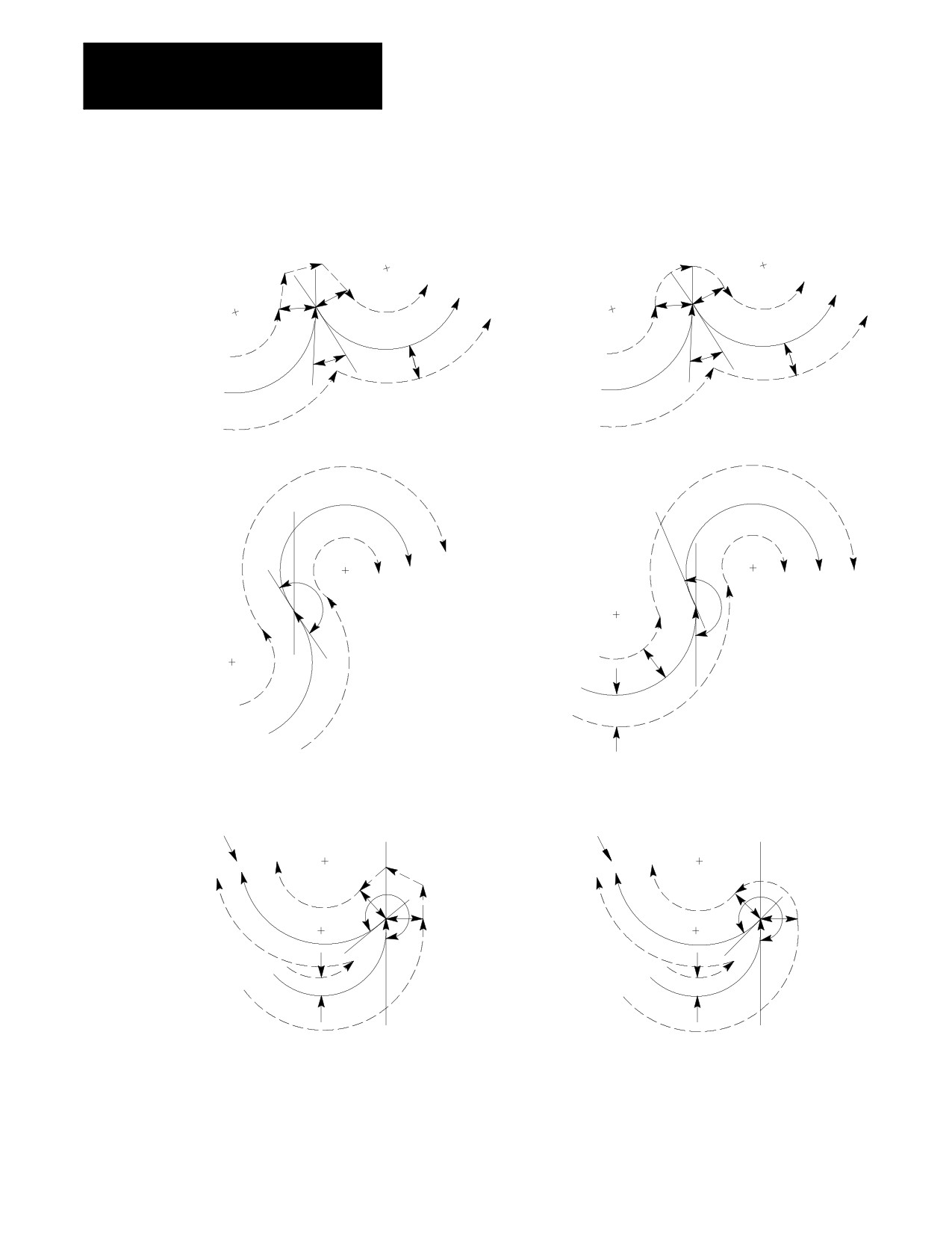
Figure 21.25 through Figure 21.28 illustrate the basic motion of the cutting
tool as it executes program blocks during TTRC.
Figure 21.25
TTRC Tool Paths Straight Line-to-Straight Line
G39 (Linear Generated Block)
G39.1 (Circular Generated Block)
Linear
0
£q £90
0
£q £90
generated block
Circular
generated block
r
G41
G41
r
r
Programmed path
Programmed path
r
r
r
q
q
r
r
G42
G42
r
r
90
£q £180
180
£q £270
G41
r
r
Programmed path
G41
r
r
q
Programmed path
r
r
q
G42
r
r
G42
G39 (Linear Generated Block)
G39.1 (Circular Generated Block)
270
£q £360
270
£q £360
Circular
generated
Linear
r
r
block
r
generated
r
block
G41
G41
r
Programmed path
r
Programmed path
r
r
q
q
r
r
G42
r
G42
12121-I
21-31
Chapter 21
Tool Tip Radius Compensation (TTRC)
Function
Figure 21.26
TTRC Tool Paths Straight Line-to-Arc
G39 (Linear Generated Block)
G39.1 (Circular Generated Block)
0
£q£90
0
£q£90
Linear
generated
Circular
blocks
generated
block
r
r
r
r
q
q
r
Programmed
Programmed
path
path
G41
G42
G41
G42
90
£q£180
180
£q£270
G41
Linear
generated
block
r
Programmed
path
r
r
r
r
r
q
r
G41
G42
q
r
Programmed
path
Linear
G42
generated
block
G39 (Linear Generated Blocks)
G39.1 (Circular Generated Block)
270
£q£360
270
£q£360
G42
G41
G42
G41
Programmed
Programmed
path
path
Linear
r
Circular
r
generated
generated
q
q
blocks
r
block
r
12122-I
21-32
Chapter 21
Tool Tip Radius Compensation (TTRC)
Function
Figure 21.27
TTRC Tool Paths Arc-to-Straight Line
G39 (Linear Generated Blocks)
G39.1 (Circular Generated Block)
0
£q£90
0
£q£90
Linear
Circular
r
generated
generated
r
r
blocks
block
r
q
q
r
r
Programmed
Programmed
path
path
G41
G42
G41
G42
Linear
90
£q£180
generated
180
£q£270
block
r
q
Programmed
path
q
r
Programmed
path
Linear
generated
block
G41
G42
G41
G42
Linear
generated
Circular
G39.1 (Circular Generated Block)
G39 (Linear Generated Blocks)
270
£q£
360
blocks
270
£q£360
generated
r
block
r
Programmed
r
r
q
r
Programmed
path
path
q
r
G41
G42
G41
G42
12123-I
21-33
Chapter 21
Tool Tip Radius Compensation (TTRC)
Function
Figure 21.28
TTRC Tool Paths Arc-to-Arc
G39 (Linear Generated Block)
G39.1 (Circular Generated Block)
0
£q £90
0
£q £90
r
r
r
r
r
r
r
r
q
q
G41
G41
r
r
Programmed
Programmed
path
path
G42
G42
90
£q £180
180
£q £270
q
q
G41
r
Programmed
path
G41
r
G42
Programmed
path
G42
G39 (Linear Generated Block)
G39.1 (Circular Generated Block)
270
£q £360
270
£q £360
Programmed
Programmed
path
path
G42
G42
G41
G41
r
r
q
q
r
r
r
r
12124-I
21-34
Chapter 21
Tool Tip Radius Compensation (TTRC)
Function
21.6
The following subsections describe possible tool paths that can be
generated when programming one of the following during TTRC:
TTRC Special Cases
changing TTRC direction (cross-over tool paths)
exceeding the allowable number of consecutive, non-motion blocks
during TTRC
corner movement following a generated block
changing cutter radius during TTRC
effect on TTRC when interrupting a program to execute either a MDI
program or a manual move
changing or offsetting current work coordinate system during TTRC
moving to and from machine home and secondary machine home
21.6.1
This section describes the resulting tool path when a change in
compensation direction (left or right) is programmed. This can result in
Changing TTRC Direction
the cutting tool crossing over the programmed tool path as compensation
changes from left to right or right to left.
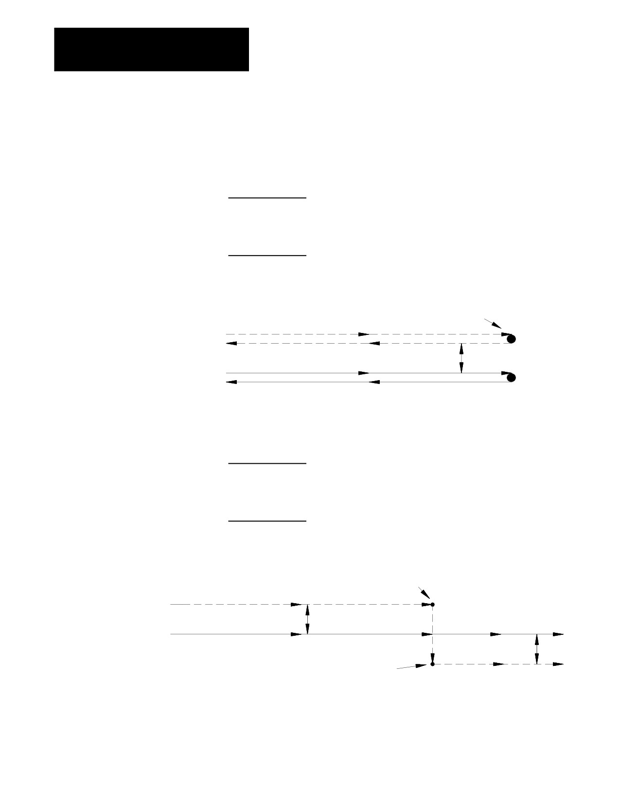
Linear Tool Path-to-Linear Tool Path.
The following figures show the tool path taken when TTRC is changed
from G41 to G42 during the execution of two linear program moves.
The control generates two points when changing TTRC direction: point 1
and point 2.
Point 1 is the final tool position before compensation direction is
changed (at right angles to the end-point of the programmed tool path
offset by one tool radius)
Point 2 is the desired tool position for the start of the first block using
the changed compensation direction (at right angles to the start-point of
the motion block that changes compensation direction and offset by the
tool radius)
21-35
Chapter 21
Tool Tip Radius Compensation (TTRC)
Function
The control generates the motion block that connects point 1 to point 2 as
shown in these examples:
Example 21.11
Linear-to-Linear Change in TTRC Direction (Reversing Tool Path)
N10 Z10.G41;
N11 Z20.;
N12 Z10.G42;
N13 Z0.;
Figure 21.29
Results of Example 21.11
Point 1 & 2
Compensated
N10
Programmed G41
N11
N13
Programmed G42
N12
Example 21.12
Linear-to-Linear Change in TTRC Direction (Continuing Tool Path)
N10 Z10.G41;
N11 Z20.;
N12 Z30.G42;
N13 Z35.;
Figure 21.30
Results of Example 21.12
Point 1
Compensated
r
Programmed G41
G41
G42
N10
N11
N12
N13
r
Point 2
21-36

Chapter 21
Tool Tip Radius Compensation (TTRC)
Function
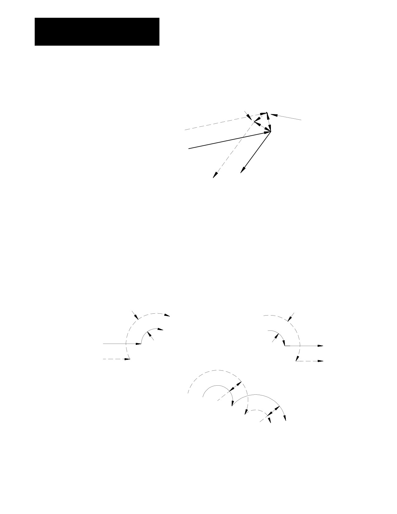
Example 21.13
Linear-to-Linear Change in TTRC Direction (With Generated Blocks)
N10 X15.Z10.G41;
N11 X-5.Z8.;
N12 X0.Z35.G42;
Figure 21.31
Results of Example 21.13
r
r
r
r
N11
Compensated
path
N10
Programmed
path
G41
N12
G42
r
r
Point 2
Point 1
Example 21.14
Linear-to-Linear Change in TTRC Direction (No Generated Blocks)
N20 X5Z10.G41;
N21 X-5.Z7.G42;
21-37
Chapter 21
Tool Tip Radius Compensation (TTRC)
Function
Figure 21.32
Results of Example 21.14
Point 2
Point 1
Compensated
path
N20 (G41)
Programmed
path
N21 (G42)
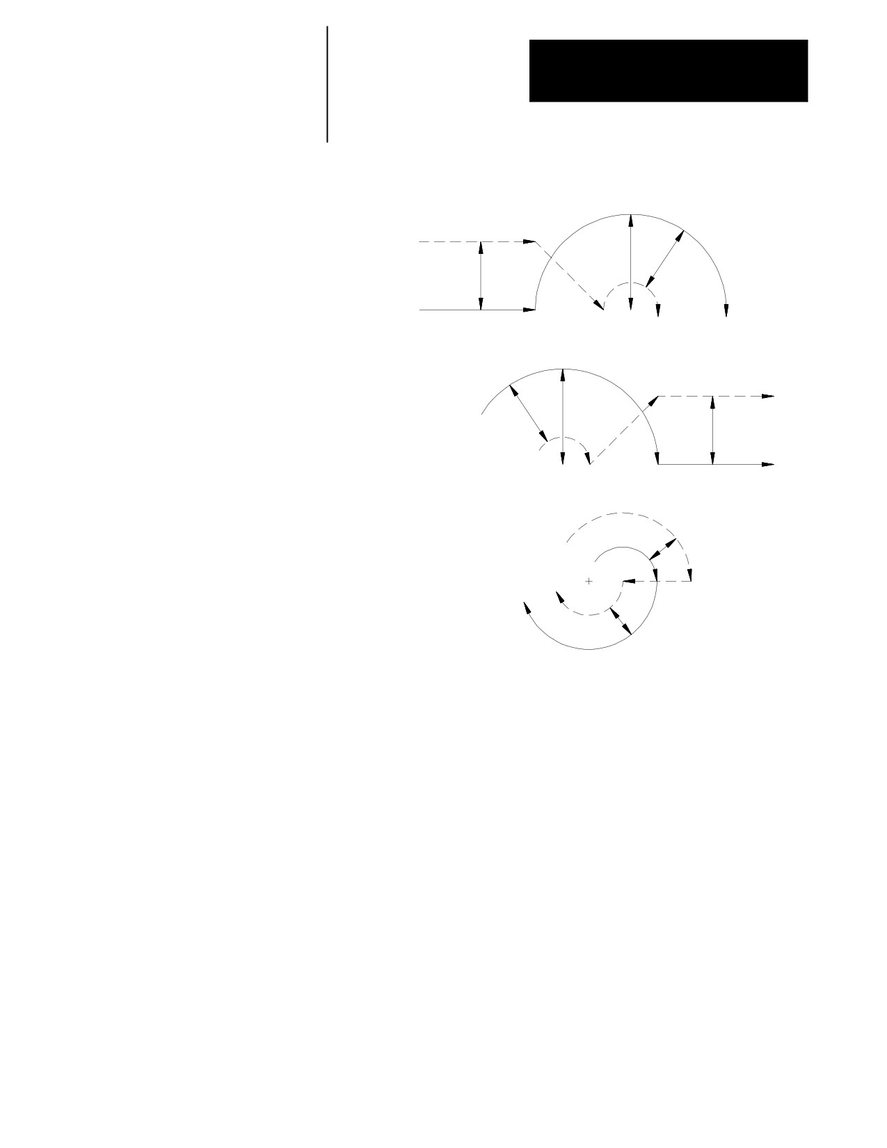
For one of these cases that changes the TTRC direction, the control
attempts to find an intersection of the actual compensated tool paths:
Linear-to-Circular, Circular-to-Linear, or Circular-to-Circular Tool Paths
If the control finds an intersection, it modifies the end-point of the original
compensated tool path and the start-point of the new compensated tool
path to equal that intersection. See Figure 21.33.
Figure 21.33
Change in Compensation with Actual Tool Path Intersection
G42
r
r
G41
Programmed G42
+
Programmed
+
path
Compensated
path
Compensated
path G41
Compensated path G41
r
Programmed path
+
r
+
G42
If no intersections of the actual tool paths exist, the compensated tool path
is the same as if a linear-linear intersection had taken place. See
Figure 21.34.
21-38
Chapter 21
Tool Tip Radius Compensation (TTRC)
Function
Figure 21.34
Change in Compensation With No Possible Tool Path Intersections
Compensated path
r2
r1
r1
Programmed path G41
G42
r1
r2
Programmed path G42
r1
Compensated path
G41
Compensated path
r
Programmed path G41
G42
r
21.6.2
The control always looks ahead to the next motion block to determine the
actual tool path for a motion block in TTRC. If the next block is not a
Too Many Non-Motion
motion block, the control continues to scan ahead for a motion block until
Blocks
it either detects one or the allowable number of non-motion blocks as set in
AMP has been exceeded. Refer to documentation prepared by your system
installer for the allowable number of non-motion blocks allowed in a
specific system.
Important: The definition of a non-motion block is any block within a
program that does not actually generate the movement of one of the axes in
the current compensated plane. Blocks that are skipped by the control
because of the block skip feature (/) are also counted as a non-motion
block in TTRC, regardless of the content of the skipped block.
21-39
Chapter 21
Tool Tip Radius Compensation (TTRC)
Function
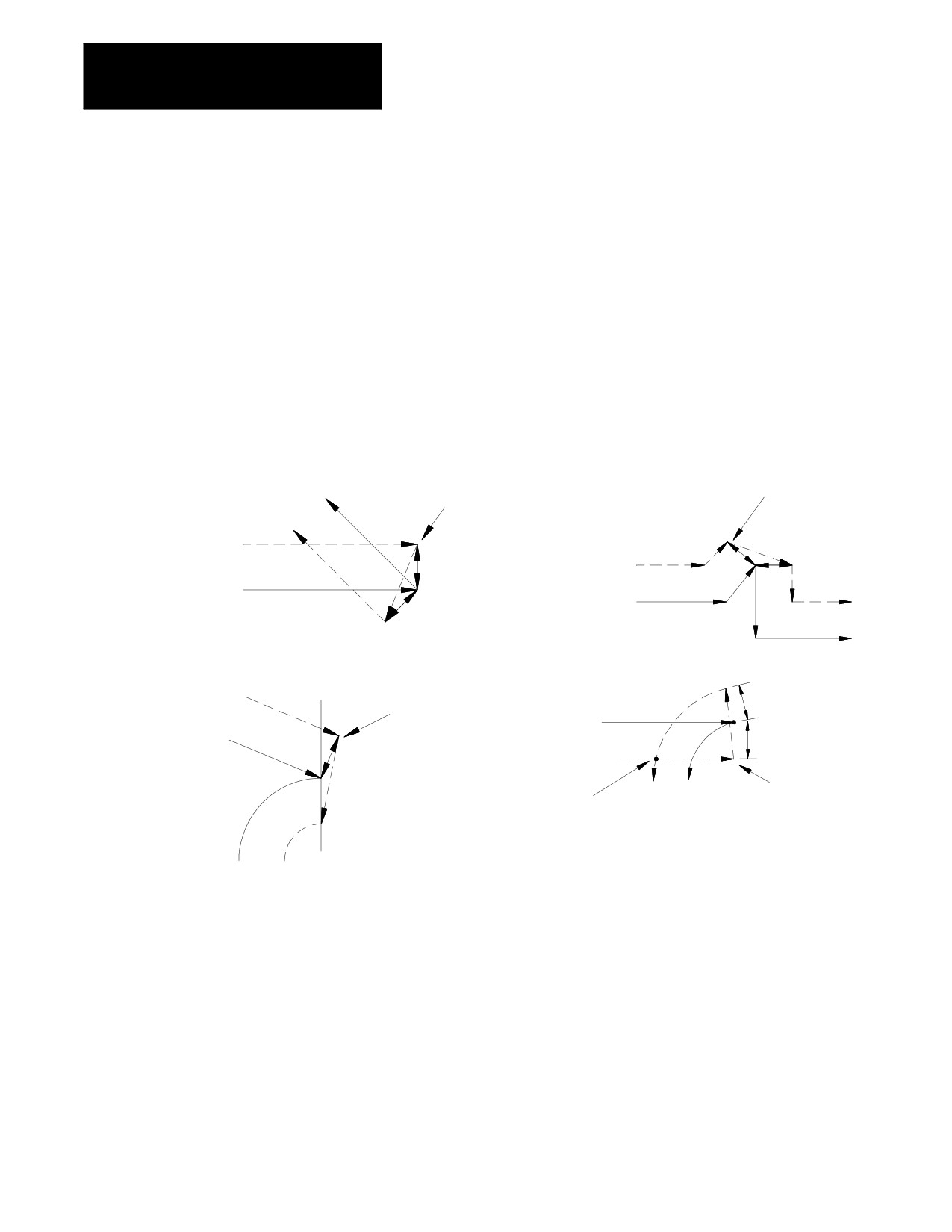
When scanning ahead, if the control does not find a motion block before
the number of non-motion blocks has been exceeded, it does not generate
the normal TTRC move. Instead the control sets up the compensation
move with an end-point one-tool radius away from and at right angles to,
the programmed end-point. In many cases this may cause unwanted
overcutting of a work piece.
In many cases, this can cause unwanted overcutting of a work piece.
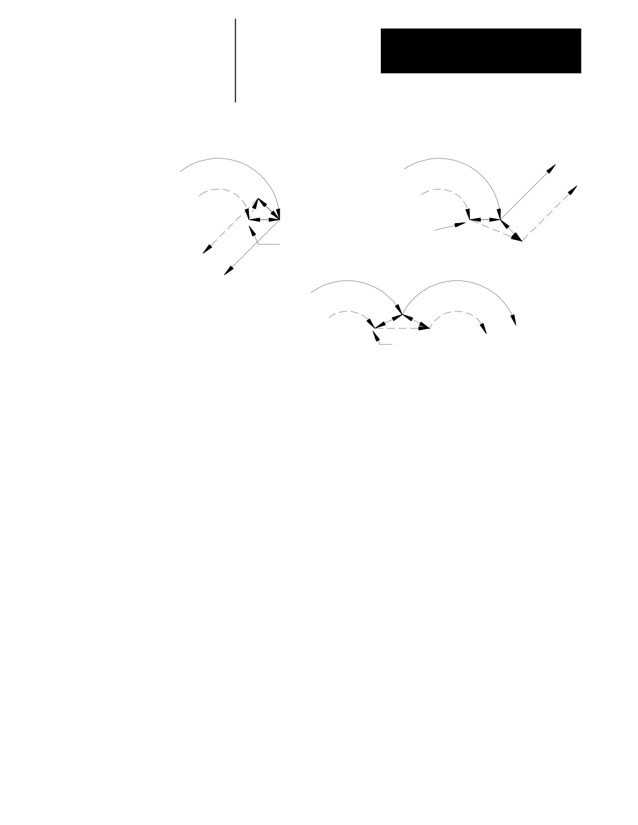
Figure 21.35 and Figure 21.36 are example tool paths of programmed
motion blocks followed by too many non-motion blocks before the next
move was made.
Figure 21.35
Too Many Non-Motion Blocks Following a Linear Move
Too many
Too many
non-motion
non-motion
Compensated
blocks here
blocks here
path, G41
Compensated
path, G41
r
Programmed
r
r
path
Programmed
path
r
Compensated
path, G41
r
Programmed
Too many
Programmed
non-motion
path
r
path
blocks here
Compensated
r
path, G42
Too many
non-motion
End-point of compensated
blocks here
move if not too many non-mo-
tion blocks
21-40
Chapter 21
Tool Tip Radius Compensation (TTRC)
Function
Figure 21.36
Too Many Non-Motion Blocks Following a Circular Move
Programmed
path G42
Programmed
path G42
Compensated
path
Compensated
path
r
r
+
+
r
Too many non-motion
Too many
blocks here
non-motion
blocks here
Programmed
path G42
r
r
Compensated
path
+
+
Too many
non-motion
blocks here
21.6.3
Frequently the control must generate motion blocks to position the cutting
Corner Movement After
tool in the proper alignment for a following compensated cutting move.
These blocks are generated to make certain that the cutting tool remains at
Generated Blocks
least one radius of the cutting tool away from the programmed cutting path
at all times.
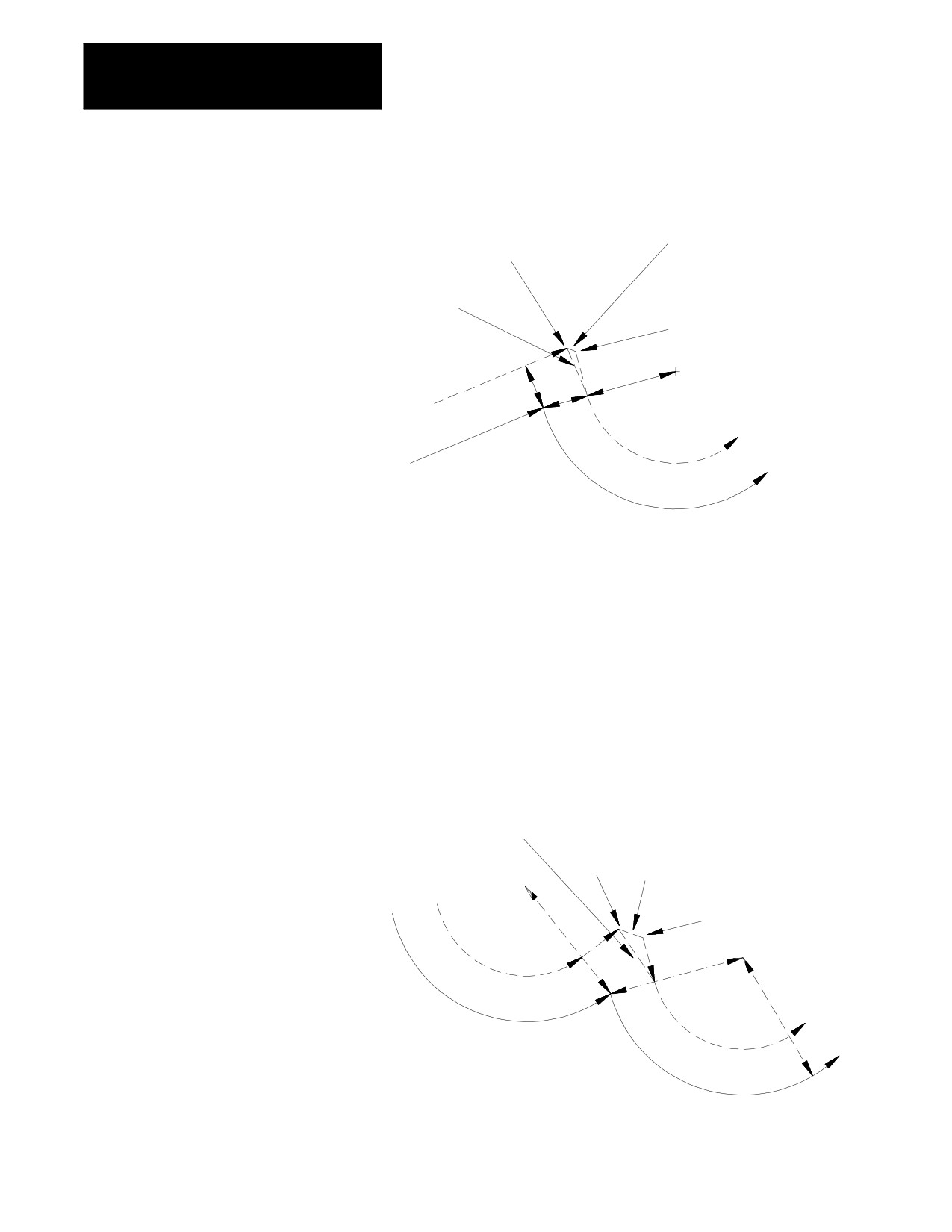
When the control generates two motion blocks, the length of the first
generated block is checked against a minimum allowable length as
determined in AMP by your system installer. The coordinate values for the
current axes in the compensation plane are compared to the minimum
allowed value. If both are less than the allowed value, then the control
does not executes the first generated block. The path of the second
generated block is then altered to position the cutting tool along a linear
path to the original end-point of the second generated block. See
Figure 21.37 for a pictorial representation.
21-41
Chapter 21
Tool Tip Radius Compensation (TTRC)
Function
Figure 21.37
Compensation Corner Movement for Two Generated Blocks
This block is eliminated if both
X1Z1
hX1-X2h and hZ1-Z2h are
less than AMP parameter
New block if block
is eliminated
X2Z2
Compensated
Programmed
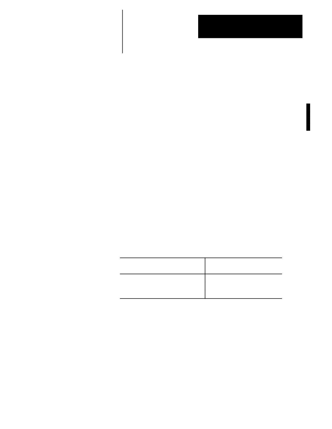
When the control generates 3 motion blocks, the length of the second
generated block is checked against a minimum allowable length,
determined in AMP by your system installer. The amount of motion of the
second move on the two axes in the compensation plane is compared to the
minimum allowed value for each axis. If both are less than the allowed
value, then the control does not execute the second generated block. The
path of the third generated block is then altered to position the cutting tool
along a linear path to the original end-point of the third generated block.
See Figure 21.38 for a pictorial representation.
Figure 21.38
Compensation Corner Movement for 3 Generated Blocks
New block if block from X1 Z1
to X2 Z2 is eliminated
This block is eliminated if both
| X1-X2 | and | Z1-Z2 | are
X1 Z1
less than AMP parameter
+
X2 Z2
+
21-42
Chapter 21
Tool Tip Radius Compensation (TTRC)
Function
21.6.4
If a tool becomes excessively worn, broken, or for any other reason
requires the changing of the programmed tool tip radius, TTRC should be
Changing Cutter Radius
cancelled and re-initialized after the tool has been changed. See page
During Compensation
NO TAG on changing the tool offset and page on changing the active tool
offset number.
Important: Slight overcutting may occur during Cutter Compensation,
depending on the programmed path at the point where the change in cutter
radius was made. To avoid overcutting, we recommend that you use a
Mid--Start Program until the point of tool breakage.
Figure 21.39 through Figure 21.41 are representations of the resulting tool
paths after the programming of a change in the radius of the cutting tool.
Assume in these figures that the programmed change to the tool radius is
entered in block N11 which also contains the motion as described in the
figure.
The tool path taken when changing tool radius is dependant on the move
immediately before the change in radius was programmed, the move that
the change in radius was programmed in, and whether any generated
motion blocks were made between these tool paths.
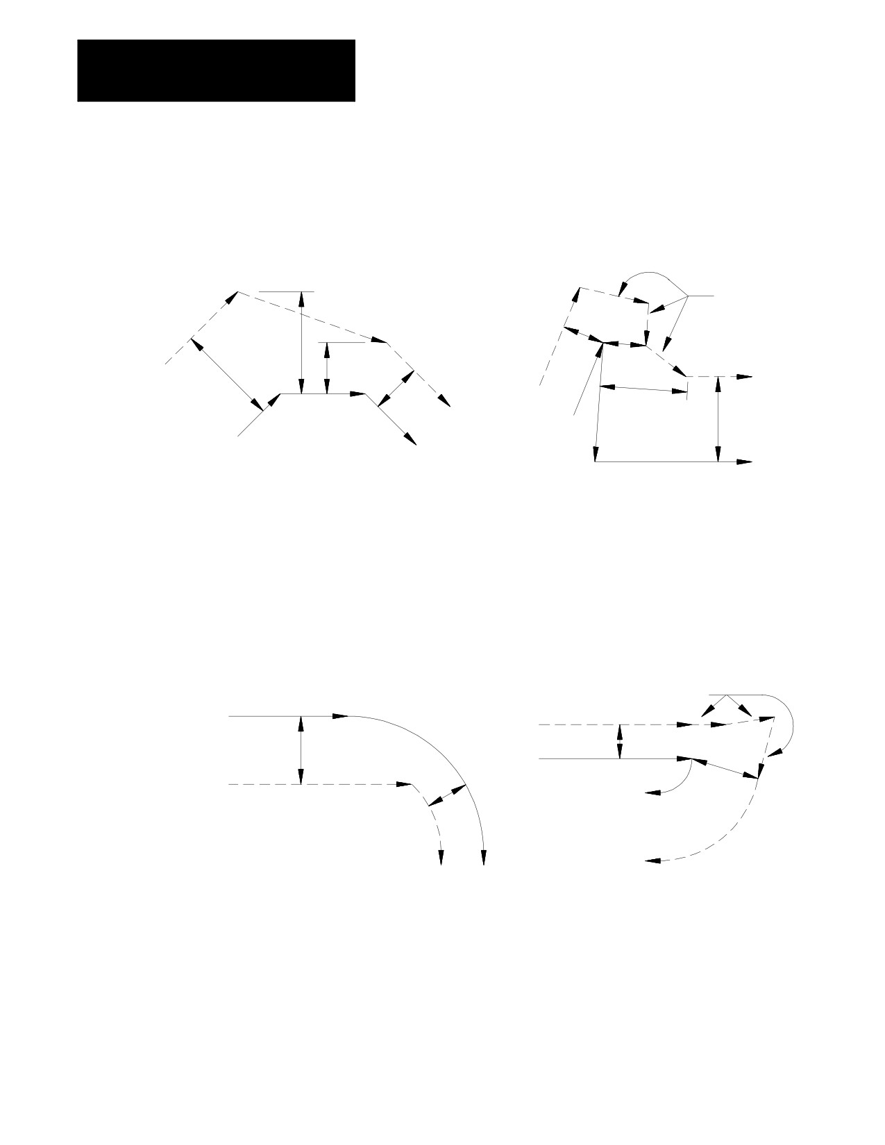
Figure 21.39 gives a description of the tool path when the programmed
moves are linear-to-linear.
Example 21.15
Linear-to-Linear Change in Cutter Radius
When the control generates blocks
When the control does not generate
blocks
N10 X10.Z5.G1T1;
N10 X10.Z10.G1T1;
N11 X-5.Z3.T2;
N11 Z20.T2;
N12 Z20.G42;
N12 X0.Z30.;
21-43
Chapter 21
Tool Tip Radius Compensation (TTRC)
Function
Figure 21.39
Linear-to-Linear Change in Cutter Radius During Compensation
With control generated
No control generated
motion blocks
motion blocks
N10
N10
Generated
N11 D_
N11 D_
blocks
N12
N12
r
1
r1
r1
r1
r
1
r2
Compensated
r1
N10
path
r2
Compensated
r2
N11
path
N11
r2
Programmed
Programmed
N10
N12
path
path
N12
Figure 21.40 describes the tool path when the programmed moves are
linear-to-circular.
Figure 21.40
Linear-to-Circular Change in Cutter Radius During Compensation
No control generated
With control generated
motion blocks
motion blocks
Generated blocks
Programmed
Compensated
path
path
r1
r1
r1
Programmed
r2
path
Compensated
r2
path
r2
+
21-44
Chapter 21
Tool Tip Radius Compensation (TTRC)
Function
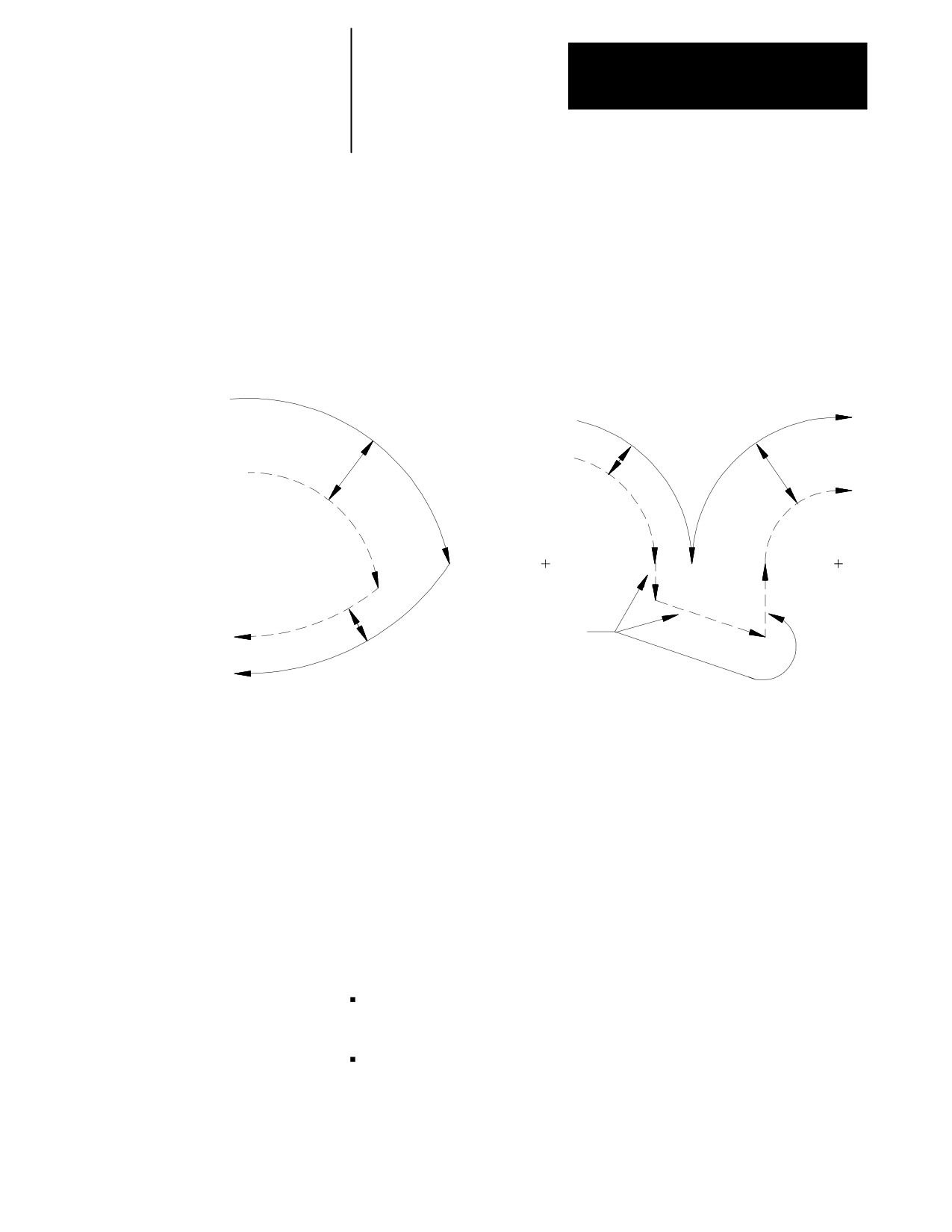
Figure 21.41 describes the tool path when the programmed moves are
circular-to-circular.
Figure 21.41
Circular to Circular Change in Cutter Radius During Compensation
No control-generated
With control-generated
motion blocks
motion blocks
Programmed
path
Programmed
path
Compensated
Compensated
path
r1
path
r2
r1
r1
r2
r2
Generated blocks
Change in Cutter Radius During Jog Retract.
This section concerns a change in the cutter radius during a jog retract
operation. The jog retract feature is often used when a tool becomes very
worn or is broken. It can be necessary to replace the tool with a tool of a
slightly different diameter. TTRC is able to adjust to the new tool
diameter.
Typically when the jog retract operation is performed, the tool is jogged
away from the workpiece and then replaced. After it is replaced, you need
to activate a different tool diameter offset value. This is done in either of
two methods:
The new offset number is activated by programming a new D-word in
an MDI block.
The new offset number is activated by using the {ACTIVE OFFSET}
softkey found on the offset table screen. This feature is described in
chapter 3.
21-45
Chapter 21
Tool Tip Radius Compensation (TTRC)
Function
The new offset is activated. TTRC is able to compensate for this new
diameter by modifying the saved jogged path. This path is modified so
that the new tool cuts the same part as the old tool. The absolute position
of the machine will, therefore, be different on the return path from what it
was when jogging away from the part.
This jogged path is adjusted when you press the <CYCLE STOP> button
to return from the jog retract. As soon as you press the <CYCLE STOP>
button, the control generates a move that offsets the current tool position
by the necessary distance. This distance is determined as the necessary
distance the tool where would have to be positioned so that the exact same
jog return paths can be used to return to the part and still have the
end-point be offset from the original position by the difference in the cutter
diameter.
CAUTION: Make sure that this offset path will not cause any
collisions with the part or the machine fixtures. The position of
the tool when the tool change in jog retract is made should be a
safe distance from the part and machine fixtures.
21-46
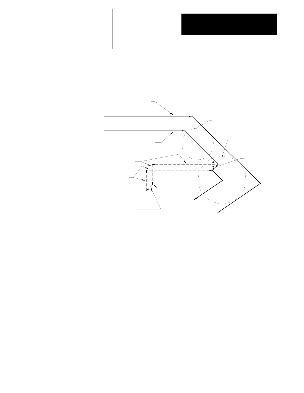
Chapter 21
Tool Tip Radius Compensation (TTRC)
Function
Figure 21.42 shows an example of a typical change in tool radius during
jog retract with TTRC active:
Figure 21.42
Change in Cutter Radius During a Jog Retract
Programmed path
Original tool
radius
New tool
Compensated path
radius
Difference in
90°
Jog retract moves
tool radius DR
Jog retract
return moves
Tool radius
changed here
Generated offset block
from difference in
tool radius DR
21.6.5
If exiting automatic mode and either a MDI motion block is executed or a
manual jog motion is made, the TTRC feature, if active, will be
MDI or Manual Motion
re-initialized when the next motion block is executed. The compensation
During TTRC
feature compensates the cutting tool one tool radius perpendicular to the
tool path of the next motion block that is executed in automatic mode. In
effect, the control generates its own entry move for compensation with the
first compensated block being the next block executed in automatic
operation.
Important: The TTRC feature is not available for any motion blocks that
are programmed in MDI mode. The TTRC mode may be altered by
programming either G41, G42, or G40, or the tool radius can be changed
in an MDI program. However, none of the tool paths executed in MDI will
be compensated. Any changes made to TTRC will not be applied until the
next block executed in automatic mode.
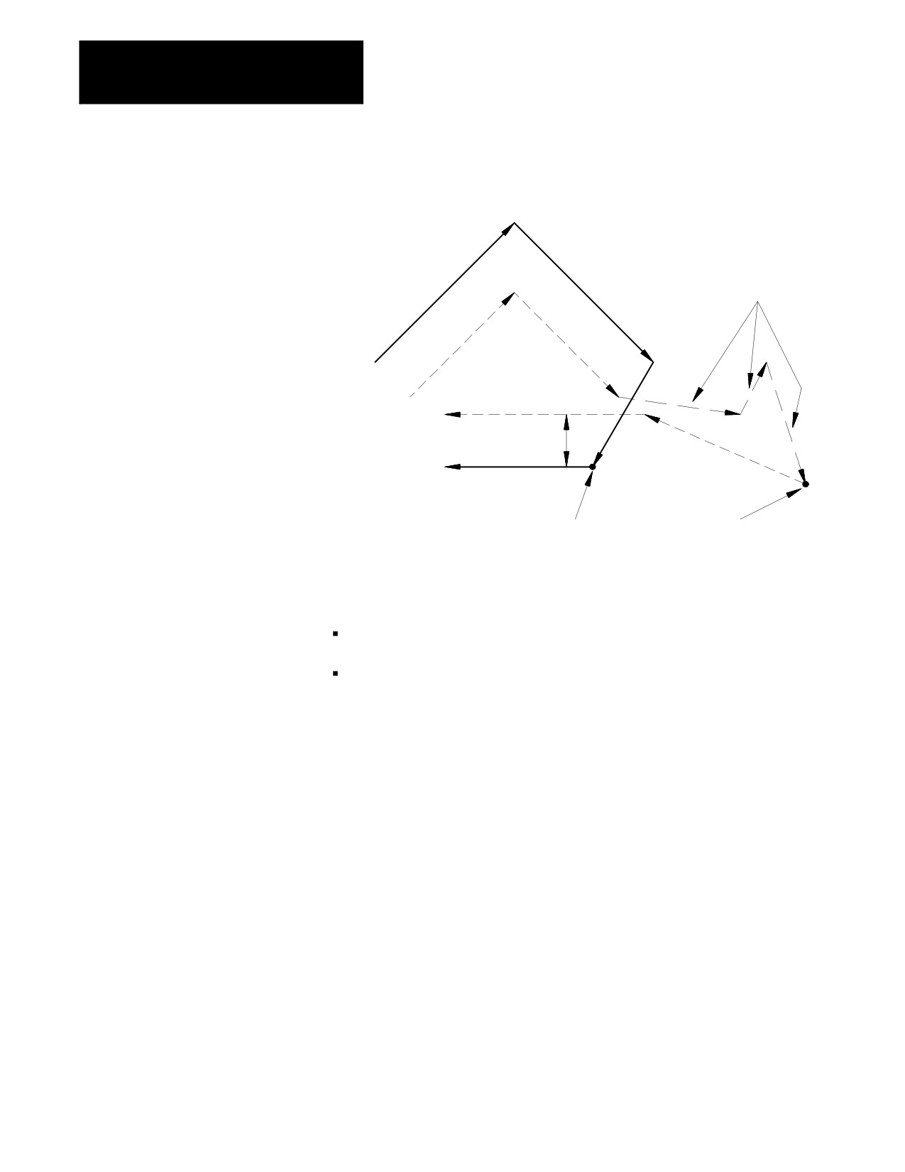
Figure 21.43 is an example of the possible tool path taken when
interrupting automatic operation during TTRC to execute MDI motion
blocks. The same tool path would apply if interrupting TTRC to perform a
manual jog move.
21-47
Chapter 21
Tool Tip Radius Compensation (TTRC)
Function
Figure 21.43
TTRC Interrupted with MDI Blocks
3 MDI blocks
(no compensation
applied)
Programmed path
G42
r
r
End-point
of MDI
Compensation
reinitializes here
Important: If during cutter compensation, you switch out of automatic
mode and either:
generate axis motion in manual mode on an axis in the cutter
compensation plane, or
execute any block in MDI mode,
cutter compensation is re-initialize when you return to automatic mode.
This produces a path that is different from the path that would have been
produced had the manual or MDI operation not been done, even if you
returned the tool to the point of interrupt. In absolute mode the control
returns to the originally compensated path after it executes a block that
contains both axes in the compensation plane. In incremental mode, the
compensated path remains offset by the additional tool radius.
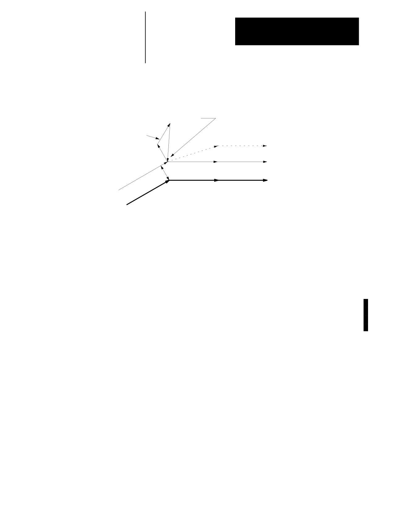
Figure 21.44 illustrates these conditions.
21-48
Chapter 21
Tool Tip Radius Compensation (TTRC)
Function
Figure 21.44
Cutter Compensation Re-Initialized after a Manual or MDI Operation.
Cutter Compensation is re-initialized here. The control assumes that the
current position is a programmed position at the point of re-initialization.
Consequently, after the initialization, tool compensation is offset by twice the
tool radius.
Manually jog axes (or any MDI
execution) and return to the
compensated path.
Over Compensated Path
(after MDI/Manual Interrupt)
Original Compensated Path
(had no interruption occurred)
Tool Radius
Programmed Path
Use the Jog Retract feature if you must jog the axes away from a
compensated path. Jog retract prevents the overcompensation from
occurring.
If you interrupt cutter compensation with a manual or MDI operation and
the next programmed block is a circular block, the control generates an
error when it tries to re-initialize cutter compensation. You can avoid this
by using the jog retract feature instead of manual or MDI when you need
to interrupt cutter compensation.
Unless Cutter Compensation is active, when a program recover is
performed, the control automatically returns the program to the beginning
of the block that was interrupted. In the case of power failure, the control
will even reselect the program that was active prior to the interruption.
21.6.6
We recommend that you cancel TTRC by using a G40 command before
Moving To/From Machine
executing a return to, or from, machine home, or a return to or from the
secondary machine home. This refers to the operations performed when
Home
the control executes either the G28, G29, or G30 commands as described
in chapter 14.
If compensation is not cancelled by using a G40 command, the control
automatically, temporarily cancels compensation for the return to machine
home or secondary machine home operations. This done by using the
move to the intermediate point, as designated when the operation was
performed, as an exit move for compensation.
Important: An intermediate point should always be programmed for a
return to home operation if TTRC is active. If no intermediate point is
21-49
Chapter 21
Tool Tip Radius Compensation (TTRC)
Function
specified, the control executes the move prior to the return to home
operation as an exit move. This can cause undesired overcutting of the
part.
If compensation was not cancelled using a G40 command before returning
to machine or secondary home points, the control automatically
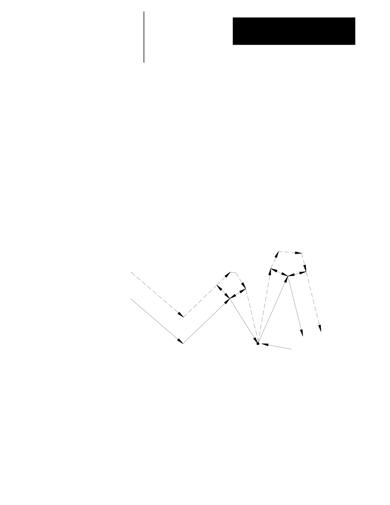
re-initializes TTRC for the return from machine or secondary home points.
This is done by using the move to the intermediate point, as designated
when the operation was performed as an entry move for compensation.
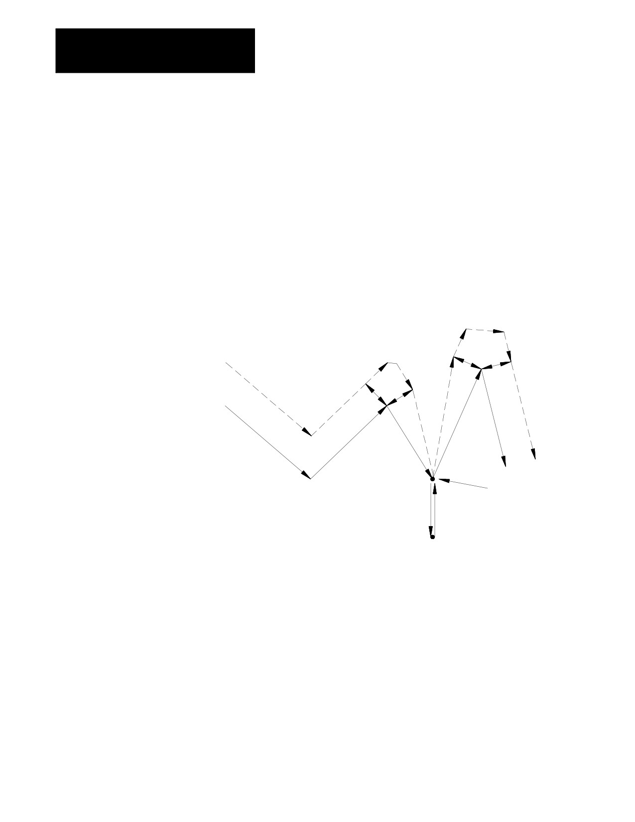
Figure 21.45 shows either a G28 or G30 block followed by a G29 block:
Figure 21.45
TTRC During G28, G30, and G29 Blocks
r
r
G41
r
r
r
r
Programmed
r
r
path
N14’
N11
N12
N15
N13
Temporary cancel of
compensation here
N13’
N14
at intermediate point
Reference point
21-50
Chapter 21
Tool Tip Radius Compensation (TTRC)
Function
21.6.7
We recommend that you cancel TTRC by using a G40 command before
any modifications to the current work coordinate system are made,
Changing or Offsetting Work
including any offsets or any change of the coordinate system (G54-G59.3).
Coordinate System in TTRC
If compensation is not cancelled using a G40 command, the control
automatically, temporarily cancels compensation for the change in work
coordinate system. This is done by using the last compensated move in the
current coordinate system as an exit move for compensation.
If compensation was not cancelled by using a G40 command before a
change in the work coordinate system was performed, the control
automatically re-initializes TTRC after the new work coordinate system is
established. This is done by using the first move in the new coordinate
system that is in the compensation plane as a entry move for compensation.
Figure 21.46 gives an example of programming a G92; however, this
would apply to any change in the work coordinate system.
Figure 21.46
TTRC During G92 Offset to Work Coordinate System
G41
r
Programmed
path
N14
N10
N11
N15
N12
N13
Temporary cancel of
compensation here
21-51
Chapter 21
Tool Tip Radius Compensation (TTRC)
Function
21.6.8
During normal program execution, the control is constantly scanning ahead
several blocks to set up the necessary motions to correctly execute the
Block Look-Ahead
current block. This is called Block Look-Ahead.
The 9/Series control has 21 set-up buffers. Different features require the
use of some of these setup buffers. One is always used for the currently
executing block. TTRC requires at least 3 of these buffers. Any remaining
setup buffers are used for block look-ahead, with one buffer used for each
block.
At times (especially during TTRC) the control may not have enough
look-ahead blocks to correctly execute the current block. When this
happens, the control automatically starts disabling the block retrace
feature.
The block retrace feature uses one setup buffer for every re-traceable
block. The number of re-traceable blocks is set in AMP by your system
installer (a maximum of 15 is possible).
If necessary, the control decreases the number of available re-traceable
blocks until either there are sufficient setup buffers available to
successfully execute the current program, or until there are no more block
retrace blocks left. The control displays a message on line 2 of the CRT if
it has to eliminate some of the block retrace blocks.
Avoid using too many buffers for block retrace. The larger the number of
look-ahead blocks that the control has available to set up future part
program motion requests, the more efficiently the control executes
programs. We recommend that you keep the number of setup buffers
available to the block retrace feature as low as possible.
21.7
Error detection for TTRC blocks can be separated into 3 categories:
Error Detection
Backwards motion detection
Circular departure too small
Interference
21-52
Chapter 21
Tool Tip Radius Compensation (TTRC)
Function
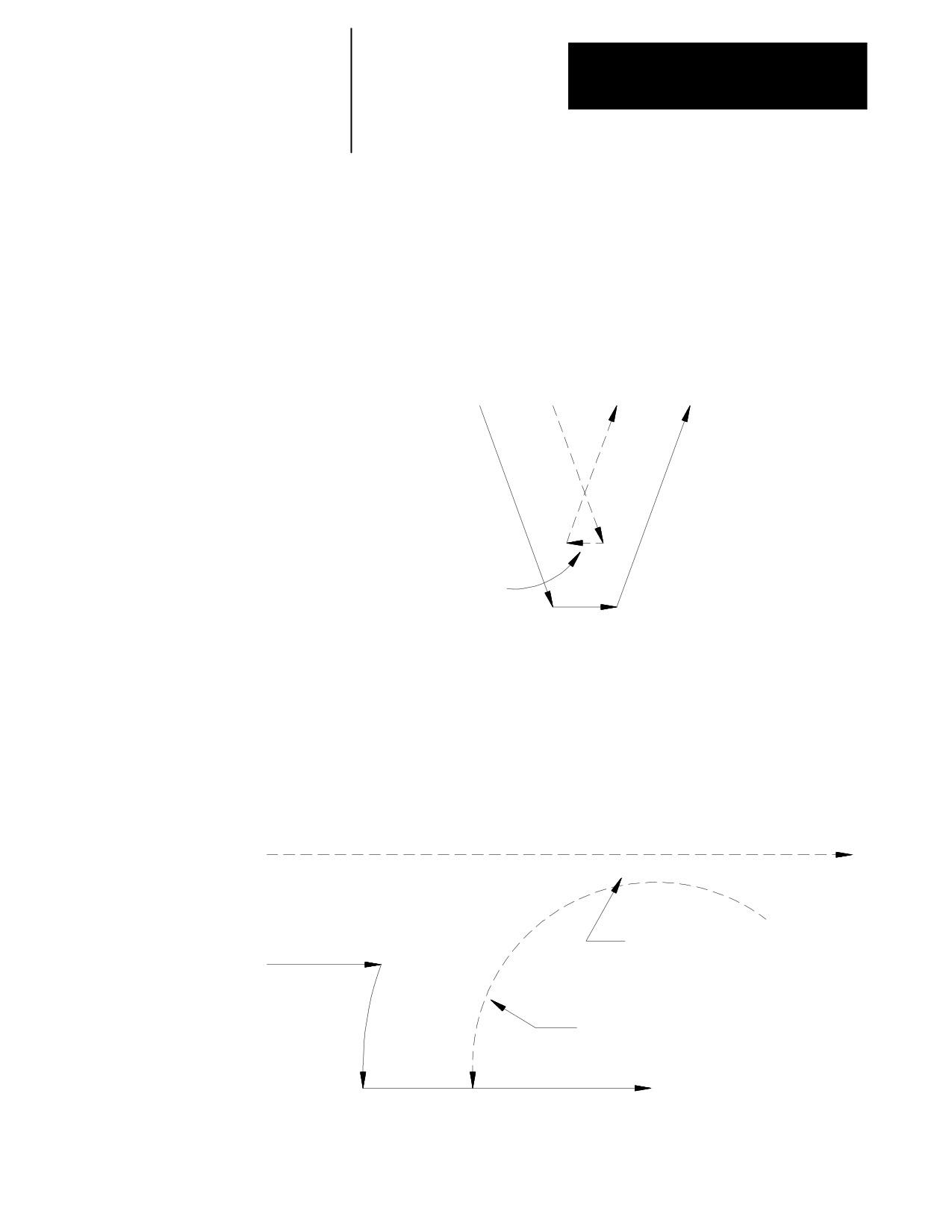
Backwards Motion Detection
The compensated tool path is parallel to but in the opposite direction of the
programmed tool path.
Figure 21.47
Typical Backwards Motion Error
Compensated
Programmed
Path
Path
D’
D
A
A’
C’ B’
Compensated path
motion opposite of
programmed path
B
C
Circular Departure Too Small
No intersection can be generated between two consecutive compensated
tool paths.
Figure 21.48
Typical Circular Departure Error
Compensated
path
Error is generated
because compensated
paths do not intersect
Programmed
path
Compensated path necessary
to cut arc
+
21-53
Chapter 21
Tool Tip Radius Compensation (TTRC)
Function
Interference
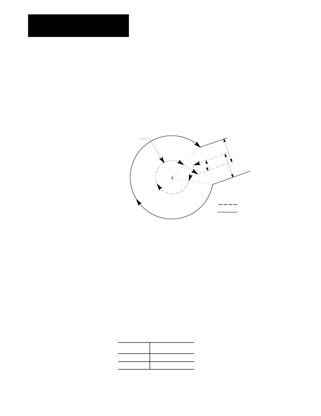
This error occurs when compensation vectors intersect. Normally when
this intersection occurs, a backwards motion error is generated; however, a
few special cases exist that are caught only by interference error detection.
Figure 21.49
Typical Interference Error
Error is generated because
compensated vectors cross
Compensated path
necessary
to cut arc
r
r
r
Compensated path
Programmed path
12145-I
Disabling Error Detection
You can disable all of the above error detection (with the exception of
circular departure too small cases) for a specific block or portion of a part
program. To disable the error detection for a specific block, your system
installer must have defined an M-code in AMP. By programming this
M-code in a block, all error detection for TTRC can be disabled. Error
detection is disabled until another M-code defined in AMP to re-enable
error detection is programmed in a block.
Important: Circular departure too small cases cannot be disabled. The
control cannot execute a compensated path when this error occurs.
The default condition is error detection enabled. Default values for these
M-codes are:
M-code:
Error detection:
M800
disables
M801
enables
21-54
Chapter 21
Tool Tip Radius Compensation (TTRC)
Function
Error detection M-codes are only functional when TTRC is active. TTRC
is active when the control is in G41 or G42 mode and has already made
the entry move into compensation. If an M800 or M801 is programmed
in G40 mode or before the entry move into TTRC takes place, the M code
is ignored.
If error detection is disabled in TTRC, and TTRC is exited (G40
programmed), the next time TTRC is re-activated error detection will be
re-activated automatically. Error detection is always automatically enabled
when cutter compensation is activated.
Refer to documentation prepared by your system installer for the M-codes
used on your specific system.
END OF CHAPTER
21-55