9/Series CNC Lathe. Operation and Programming Manual - page 16
Chapter 19
Dual Axis Operation
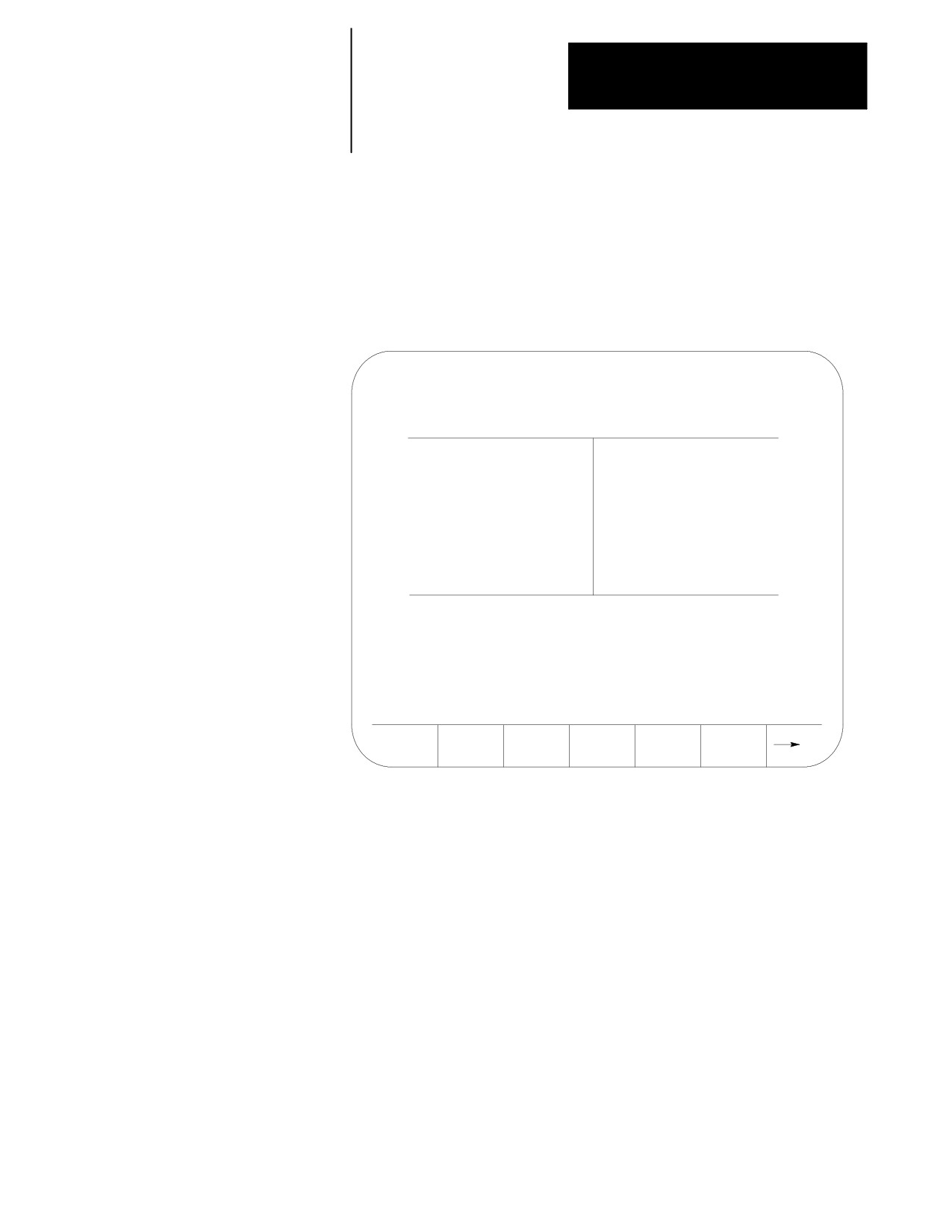
Figure 19.2 shows the position display for a system that contains a dual
axis group containing two axes with a master axis name of X. Whether or
not all axes of a dual group show up on the position display is determined
in PAL by your system installer.
Figure 19.2
Axis Position Display for Dual X Axis
E-STOP
PROGRAM[ MM
]
F
0.000 MMPM
X1
-7483.647
S
00
Z
-0219.550
T
0
U
-2345.673
(ACTIVE PROGRAM NAME)
X2
-7483.647
MEMORY
MAN STOP
PRGRAM
OFFSET
MACRO
PRGRAM
SYSTEM
MANAGE
PARAM
CHECK
SUPORT
19.1
This feature allows you or the programmer to disable selected axes of the
Parking a Dual Axis
dual group. Any axis that is a member of a dual axis group can be parked.
Axes in the dual group may be parked simultaneously. If all axes in the
group are parked, no motion can take place in the dual axis group.
Once parked, no motion is allowed on the parked axis. Programmed and
jog commands (including any homing requests) made to the dual axis
group are ignored by the parked axes.
Axes in the dual group may only be parked or unparked when the control
is in cycle stop and end-of-block state. The control cannot be in the
process of completing any jog request or PAL axis mover request. If an
attempt is made to park/unpark an axis, and if any one of the above
requirements is not true, the control ignores the request to park/unpark the
axis.
19-3
Chapter 19
Dual Axis Operation
CAUTION: Be careful when an axis is unparked. Any
incremental positioning requests you make to the dual axis
group are referenced from the current location of all axes in the
dual group. This includes any manual jogging or any
incremental part program moves. When an axis is unparked, we
recommend you make the next command the dual axis group be
an absolute command to realign the axes in the dual group to
the same position.
Perform an axis park in a dual group through PAL. Refer to your system
installer’s documentation for details on how axes are parked.
Important: Some systems can have special parking requirements when
homing axes in a dual group. See section 19.2 for details on homing dual
axes.
19.2
There are two methods to home axes in a dual axis group. Your system
Homing a Dual Axis
installer determines through PAL which method is available. The two
methods are:
home each axis in the dual group individually
home all axes in the dual group simultaneously
Both of these homing methods can be available for automatic (G28) as
well as manual homing operations.
Your system installer can also define independent speeds and home
positions for each axis in a dual group through AMP. This applies to both
homing methods. Refer to your system installer’s documentation for
details on these speeds and locations.
Homing Axes Individually
This method requires that each axis be homed individually. When a
manual home operation is performed, a home request must be made to
each axis in the dual group on an individual method. Refer to chapter 4 for
details on how to request a manual home operation.
When you use automatic homing (G28), the axes must be homed one at a
time. This is accomplished by parking all other axes in the dual axis group
except the axis that is to be homed and requesting that the AMP-assigned
master axis name be homed in the G28 block. Once homed, that axis
should be parked, the next axis to be homed should be unparked, and the
homing procedure repeated. Refer to chapter 14 for details on how to
request an automatic home operation (G28).
19-4

Chapter 19
Dual Axis Operation
Homing Axes Simultaneously
This method allows a request for all axes in the dual group to be homed at
the same time. This does not mean that all axes reach home at the same
time. Keep in mind that your system installer can define different
feedrates and different home positions for each axis in the dual group.
With proper PAL programming, your system installer can configure all
axes in the dual axis group to home when the request is made to the master
axis. If you use this homing method, all unparked axes home together.
Refer to chapter 4 for details on how to request a manual home operation
and chapter 14 on how to request an automatic home operation (G28).
19.3
You can position axes in a dual axis group using any of the normal
programming or manual motion operations. Only the master axis name
Programming a Dual Axis
can be requested to position a dual axis. Requests to position a dual axis
can be made in manual, automatic, or MDI mode.
For absolute and incremental moves, regardless of the start-point, each axis
in the dual group reaches the requested position (or travel the requested
distance) at the same time. For absolute moves, this means individual axis
feedrates can be modified, depending on the distance each axis must travel
from start to end of the requested move.
Your system installer can assign different maximum cutting, external decel,
and rapid feedrate limitations for each axis in a dual axis group. The
control uses the slowest feedrate for each of these features from any axis in
the dual axis group.
Special consideration must be given when programming these features:
Feature:
Consideration:
Mirror Imaging
Programmable mirror image is applied to all axes in the dual group. Manual
mirror image, however, can be applied to each axis in the dual group individually.
When manual mirroring is performed on selected axes in the dual group,
positioning commands are in effect reversed from the programmed commands to
the master axis. Manual mirror image is selected through PAL. Refer to the
system installer’s documentation and chapter 14 for details.
Scaling
When scaling, specify the scale factor for the master axis of the dual group. All
other axes in the dual group are then scaled using the master axis scale factor.
Refer to chapter 13 for details.
Digitizing
When generating program blocks using digitize, park all but one axis of the dual
axis group. Use this unparked axis to generate the axis positions for the digitize
feature. The blocks created are stored using the master axis name. Refer to
chapter 5 for details.
19-5

Chapter 19
Dual Axis Operation
Important: You can use the PAL axis mover feature if it is necessary to
position dual axis group members separately without requiring any
parking. Refer to the PAL manual and the system installer’s
documentation for details.
Invalid Operations on a Dual Axis
Table 19.A lists the features that are not compatible with dual axes. If you
must execute one of these features on a dual axis, only the AMP master
axis can be used. All other axes in the dual group must be parked.
Refer to your system installer’s documentation to determine which axis has
been assigned in AMP as the master axis.
Table 19.A
Features Not Compatible With Dual Axes
G-code
Feature
G16.1
Virtual C Cylindrical Interpolation
G16.2
Virtual C Cylindrical End Face Milling
G20, G24
Single Pass Roughing
G21
Single Pass Threading
G31-G31.4
External Skip Functions
G33, G34
Thread Cutting Mode
G37-G37.4
Automatic Tool Gauging Skip Functions
G72-G75
Roughing Cycles
G76
Face Grooving Cycle
G77
Grooving Cycle
G78
Multi-Pass Threading Cycle
G84.2, G84.3
Solid Tapping
G86.1
Boring Cycle w/Shift
G87
Back Boring Cycle
19-6
Chapter 19
Dual Axis Operation
19.4
Give consideration to offsets used for a dual axis. In most cases, each axis
can have independent offset values assigned to it. This section describes
Offset Management for a
the difference in dual axis operation when it concerns offsets. How to
Dual Axis
activate/deactivate and enter these offset values is not described here
unless some change specific to a dual axis occurs. See chapter 3 for
implementation details about the offset you are using.
Preset Work Coordinate Systems (G54-G59.3)
The operation of the work coordinate systems is functionally the same for
a dual axis as any other axis. Each axis in the dual group can have its own
independent value entered into the offset table. If you want all axes in the
dual group to have the same offset values, you must manually enter the
same value for each axis in the dual group.
G52 Offsets
All axes in the dual group use the same value for the G52 offset regardless
of whether they are parked. When you specify a G52 offset value using
the master axis name, each axis offsets its coordinate system incrementally
by the G52 amount.
G92 Offsets
When a G92 offset value is specified using the master axis name, the
current position of all axes in the dual group takes on the location of the
specified value.
For example, if you have a dual axis named X, and it consists of two axes,
X1 and X2, when programming the following:
G92X10;
the control causes the current positions of X1 and X2 to become 10
regardless of their current positions when the G92 offset is executed.
Different G92 offset values can be created for each axis if necessary. This
is accomplished by performing a jog offset or by using the PAL axis mover
to change the position of the dual axes relative to each other before the
G92 block is executed.
19-7
Chapter 19
Dual Axis Operation
Set Zero
You can perform a set zero operation on the axes in a dual group on an
individual basis. For example, if you have a dual axis named X and it
consists of two axes, X1 and X2, when the set zero operation is executed
through PAL, you must specify which axis in the dual group to set zero.
When the set zero operation is performed on an axis, the current axis
location becomes the new zero point of the coordinate system.
Cutter Compensation
Only one tool diameter can be active at any one time. Any offset created
by cutter compensation affects all axes in the dual group.
Tool Length Offsets
Functionality is the same as for any other axis; independent values can be
entered for each axis in the dual group. A T-word selects the length offset
number, and the tool length offset is activated for each axis. Refer to
chapter 20 for details on activating tool length offsets.
Additional programming for the G10L10 and G10L11 codes are available
when a dual axis is the tool length axis. Since each axis in the dual group
can have separate offset values, the G10 block must contain an individual
name for each axis being assigned a value. Just programming the master
axis name assigns values only to the master axis. Your system installer
assigns axis names to all axes in the dual group in AMP. Refer to your
system installer’s documentation for details.
END OF CHAPTER
19-8
Chapter
20
Tool Control Functions
20.0
This chapter describes these tool control functions:
Chapter Overview
Topic:
On page:
Programming a T-word
20-3
Entering tool offset data
20-6
Tool management
20-14
Programming a T-word ---- Different formats available for selecting a
tool number and tool offsets
Tool length offsets ---- Compensate for the difference between the tool
length assumed while programming, and the actual length of the tool
used for cutting. This feature can offset up to 4 axes.
Tool Management and Random Tool ---- Tool life monitoring and tool
changer pocket control
Important: Tool Tip Radius Compensation compensates for the difference
between the tool diameter assumed while programming and the actual
diameter of the tool used for cutting (eliminates overcutting or uncut
portions of a workpiece due to differences in tool orientations and tip
radius) as described in chapter 21.
20-1

Chapter 20
Tool Control Functions
20.1
Modern machining processes usually require a machine that is capable of
selecting different tools. Typically tools are mounted in a turret and
T-words and Tool Length
assigned tool numbers as illustrated in Figure 20.1. The tool length offset
Offsets
data, tool tip radius data, tool wear compensation data and tool orientation
data are set in the offset table corresponding to different offset numbers
See chapter 3.
Figure 20.1
Typical Lathe Tool Turret
07
06
08
05
01
04
02
03
The selection of a tool number and an offset number for that tool is done
by programming a T-word. A T-word can be programmed at any location
in a part program.
Important: When you activate the MISCELLANEOUS FUNCTION
LOCK feature, the control displays M-, B-, S-, and T-words in the part
program with the exception of M00, M01, M02, M30, M98, and M99.
Activate this feature through the front panel screen (as described in chapter
2) or by an optional switch installed by your system installer.
20-2

Chapter 20
Tool Control Functions
20.1.1
Important: If tool life management is being used on the system, see the
Programming a T-word and
tool management section in this chapter for details on programming a
Tool Offsets
T-word. This section assumes that the tool life management feature is not
being used.
Your system installer determines the format for a T-word in AMP.
Table 20.A shows the 6 available format selections.
Table 20.A
T-word Formats
* FORMAT TYPE
WEAR OFFSET #
GEOMETRY OFFSET #
(1) 1 DGT GEOM + WEAR
last digit
same as wear
(2) 2 DGT GEOM + WEAR
last two digits
same as wear #
(3) 3 DGT GEOM + WEAR
last three digits
same as wear #
(4) 1 DGT WEAR
last digit
same as tool #
(5) 2 DGT WEAR
last two digits
same as tool #
(6) 3 DGT WEAR
last three digits
same as tool #
* For details on which format is being used on a specific control refer to documentation prepared by the system installer.
To use Table 20.A find the format being used on your system. Then go
down the wear offset # column and find which digits of the T-word are
used as the wear offset number. Any other digits to the left of the wear
number are used as the tool number. If there are no digits remaining to the
left of the wear number, the control uses tool number 0. The third column,
geometry offset #, tells if the geometry number is the same number as the
number used for wear or tool. Just because geometry may use the same
offset number as wear it is not necessarily calling the same offset value.
Example 20.1
Using T-word Format #5
T213;
This T-word first calls for tool number 2 to be rotated into position, then data is accessed from
the offset tables (chapter 3) for values under tool geometry offset number 2, and tool wear offset
number 13.
20-3

Chapter 20
Tool Control Functions
Example 20.2
Using T-word Format #3
T2013;
This example first calls for tool number 2 to be rotated into position, then data is accessed from
the offset tables (chapter 3) for values under tool geometry offset number 13, and tool wear
offset number 13.
From these simple examples translation to the other formats should be
relatively easy. The tool number is always the digits closest to the T-word.
The maximum value that a tool number can have is determined by the
system installer in AMP.
To cancel the tool length offset, program a T-word with a geometry and
wear offset number of 0. The control does not cancel the active tool
number since a tool number of 0 is invalid. If the wear or geometry offset
number is the same as the tool number, a T-word of 0 cancels the offsets
but not the tool number.
Example 20.3
Canceling Tool Offsets (Any T-word Format)
Assume that tool number 1 is the active tool number.
T0 ;
This example cancels all offsets and keeps tool number 1 in the turret. The system installer has the
ability to force a tool change when T0 is programmed if he desire with a specific PAL program.
Refer to your system installers documentation for details.
Important: Your system installer determines in AMP whether or not all
tool length offsets are canceled when the control is reset or an M02 or M30
end of program block is read.
Important: A T-word also calls up geometry and wear radius data for use
in TTRC. See chapter 21.
20-4

Chapter 20
Tool Control Functions
20.1.2
Your system installer has the option in AMP to determine exactly when the
geometry and wear offsets take effect and when the tool position changes
Activating Tool Length
to the new shifted location. This manual makes the assumption that the
Offsets
system is configured to immediately shift the coordinate system by the
geometry and wear amounts, and delay the move that re-positions the tool
to the same coordinate position in the current work coordinate system. See
the documentation prepared by your system installer to determine the
application in a specific system.
Provided your system is configured as described above, the control
activates a tool offset as described below:
The control reads a block that activates or deactivates a tool length
offset. This is a block that contains a T-word for the above
configuration.
The control immediately shifts the work coordinate system the amount
of the tool geometry and tool wear amounts called by the T-word.
Different values can be entered for the offsets for each axis in the offset
table. The tool position display changes reflecting this shift. The
absolute position display does not change.
The offset is interpolated into the next move that generates axis motion
on the offset axis, unless you are in incremental mode. If you are in
incremental mode, the offset is not interpolated into the next move of
the axis.
Example 20.4
Immediate Shift/Delay Move in Incremental and Absolute Modes
Absolute Mode
Incremental Mode
G00Z0
Rapid Mode
G00Z0
Rapid Mode
G90
Absolute Mode
G91
Incremental Mode
T01
Activate tool 1. Program display
T01
Activate tool 1. Program display
changes Z position to -3.
changes Z position to -3.
Z1
Axis moves to +1
Z1
Axis moves to -2
If immediate shift, immediate move is selected in AMP, the control
generates its own linear block to create the offset and positions the tool to
the coordinates in the shifted work coordinate system as they were before
the system was shifted. If axis words are present in the block that activates
or deactivates a tool length offset, the control adds this generated move to
the programmed move.
Important: A T-word cannot be programmed in a block that generates a
circular motion (G02 or G03). If you want to change tools during circular
blocks the T-word must be programmed in its own block where no axis
motion takes place.
20-5

Chapter 20
Tool Control Functions
20.2
You can enter data in the tool offset tables by programming the correct
G10 command. This section describes the use of the G10 commands for
Entering Tool Offset Data
the lathe tool offset table.
Using (G10L10, G10L11)
Important: Only the value in the offset table value changes when a G10
code modifies a tool offset table value. If the changed offset value is
currently being used by the control, the active offset value is not changed
until it is called again from the offset table using a T-word.
When the control is in incremental mode (G91), any values entered in an
offset table using the G10 command are added to the currently existing
offset values. When the control is in absolute mode (G90), any values
entered in an offset table using the G10 command replace the currently
existing offset values.
This is a representation of the basic format for modifying the offset tables.
G10 L(10-11)P__ X__ Z__ R__ Q__ T__ O__
Where :
Is :
L(10-11)
Designates which offset table is being modified.
L10-Modifies the tool geometry table.
L11-Modifies the tool wear table.
P
The tool offset number that is having its values changed is specified following the P address.
X
The value to add to (in G91 mode) or replace (in G90 mode) the tool length offset for the X axis.
This value may be a diameter or radius value as determined with the O-word.
Z
The value to add to (in G91 mode) or replace (in G90 mode) the tool length offset for the Z axis.
R
The value to add to (in G91 mode) or replace (in G90 mode) the tool tip radius amount.
Q
The value to add to or replace the tool orientation amount
(valid only when setting data for the geometry table).
T
A T-word that corresponds to the tool number that is being changed.
O
Determines if the value being entered into the offset table is a radius or diameter value. This
only applies when setting data for the controls diameter axis (typically the axis perpendicular to
the spindle). If no O-word is programmed the control uses the current radius/diameter mode
active on the control.
O1-indicates a radius value
O2-indicates a diameter value
Important: Any axis word may be entered here along with/or without the
X- or Z-words. The lathe offset table allows the entry of offsets for up to
four different axis, tool radius, and tool orientation for each offset number.
Any values not specified in the G10 block remain unchanged.
20-6
Chapter 20
Tool Control Functions
Example 20.5
Using G10 to Change The Tool Offset Table
N00001
G90;
N00002
G10 L10 P4 Z2.1 Q1;
Offset number 4 has a new value of 2.1 for tool offset in the Z
direction and new orientation value of 1 in geometry table. The
current value for any axis not specified and for the tool radius
remain unchanged.
N00003
G10 P4 L11 Z1.1;
Offset number 4 has a new value of 1.1 for tool offset in the Z
direction in the wear table.
N00004
G91;
N00005
G10 L10 P4Z-1 Q1;
Offset number 4 has a new value of 0.1 (1.1 -- 1.) for tool offset
in the Z direction and new orientation value of 2 (1 + 1). The
current value for any axis not specified and for the tool radius
remain unchanged.
Important: G10 blocks cannot be programmed when TTRC is active.
20.3
Use the random tool feature to speed up production by saving cycle time
Random Tool
when a tool is returned to the tool changing device. This is done by
allowing the tool changer to randomly return the cutting tool to the most
convenient pocket in the tool changing device. The control remembers
what pocket the tool is returned to, and it is able to call the same tool from
the new pocket at any time.
Important: This feature can be used with normal tool selection or the tool
life management feature.
This feature has no effect on tool length offsets or cutter compensation.
These features must still be activated correctly as described in their
individual sections.
The random tool feature automatically decides the pocket that contains the
requested tool based on the information in the pocket assignment table. If
the requested tool has not been assigned to a pocket, the control generates
an error.
Based on the current pocket number, which is maintained by PAL, the
control tells PAL which pocket to move to, and how far, and in which
direction to move. The control also tells PAL where the tool currently in
use can fit in the tool turret.
Important: This feature is very PAL dependant. Before using this feature
make sure your system installer has written the PAL program to allow the
use of Random Tool.
The control automatically updates the tool pocket assignment table when
you make tool changes. The control indicates to PAL the best location to
return the tool to. PAL then decides where the tool gets placed in the tool
holder. The pocket that is vacated by the new tool is marked as empty.
20-7
Chapter 20
Tool Control Functions
Manually Entering Random Tool Data
Data can be entered into the random tool table either manually, as
described here, by programming, or by running a backup program of the
tool data. These other methods are described later in this section.
To manually enter the random tool data, follow these steps:
1.
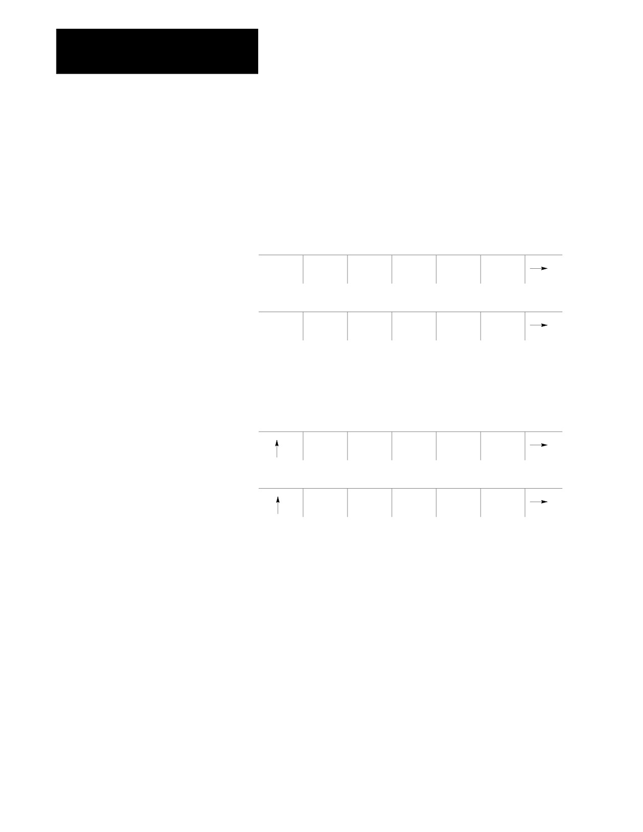
Press the {OFFSET} softkey.
(softkey level 1)
PRGRAM
OFFSET
MACRO
PRGRAM
SYSTEM
MANAGE
PARAM
CHECK
SUPORT
FRONT
ERROR
PASS-
SWITCH
PANEL
MESAGE
WORD
LANG
2.
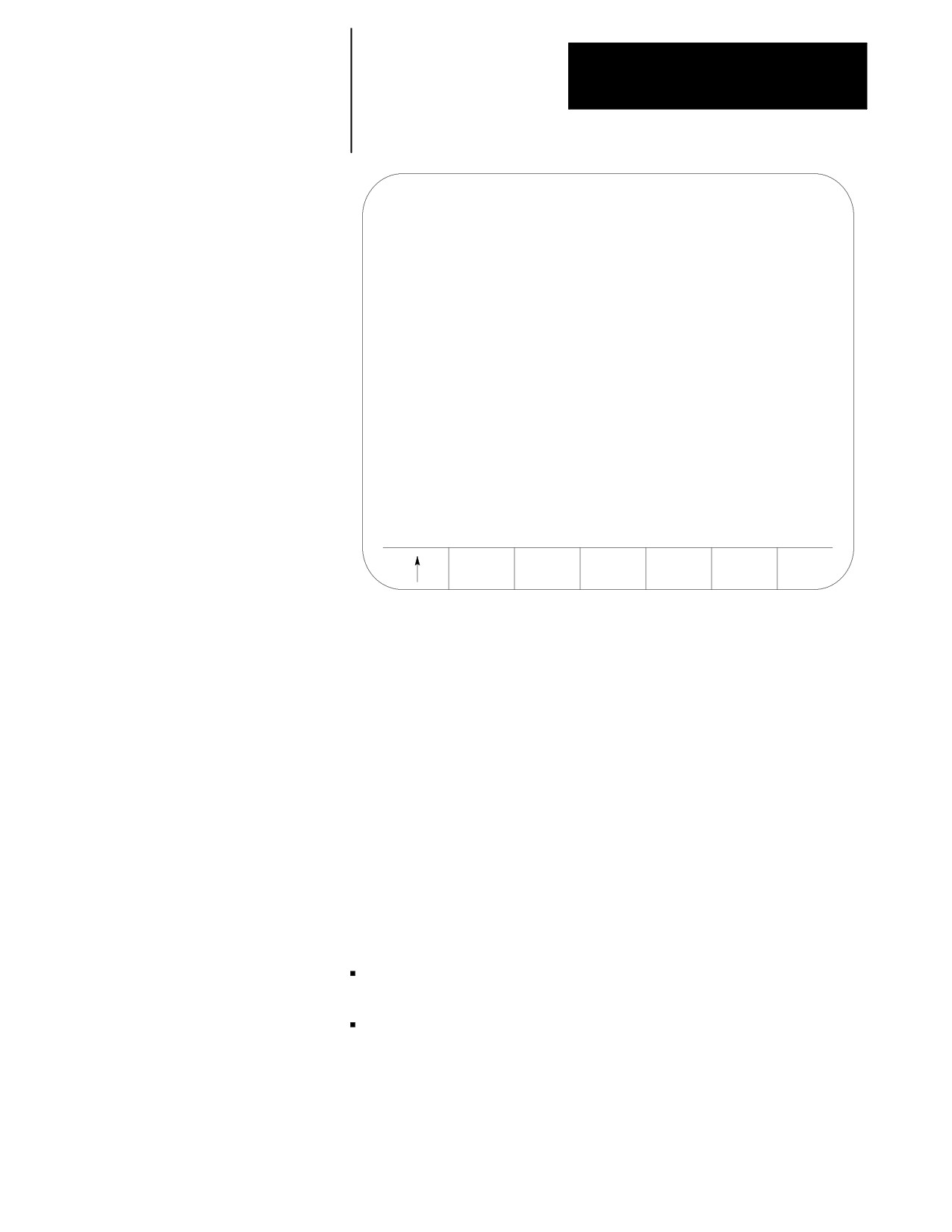
Press the {RANDOM TOOL} softkey. The pocket assignment table
screen is displayed as shown below. This screen shows the current
tool to pocket assignments. Your system installer designates the
number of tool pockets available on a system in AMP.
(softkey level 2)
WORK
TOOL
TOOL
TOOL
RANDOM
CO-ORD
WEAR
GEOMET
MANAGE
TOOL
COORD
BACKUP
SCALNG
ROTATE
OFFSET
20-8
Chapter 20
Tool Control Functions
POCKET ASSIGNMENT TABLE
PAGE 1 OF 2
PKT
TOOL
PKT
TOOL
PKT
TOOL
001
0002
002
003
0001
004
005
0003
006
XXXX
007
0007
008
XXXX
009
010
011
012
013
014
015
016
017
018
XXXX
019
0006
020
XXXX
021
022
023
024
025
026
027
028
029
030
031
032
033
034
035
036
037
038
039
RAPLCE
CLEAR
CUSTOM
ACTIVE
BACKUP
VALUE
VALUE
The columns labeled PKT give the tool changer pocket numbers. The
columns labeled TOOL give the tool number of the tool in the
corresponding pocket. Pockets with no tools assigned to them show no
information next to the pocket number. Pockets with tools shown as
XXXX indicate that a custom tool (tool that requires more than one
pocket) has been assigned to use that pocket.
3.
Move the cursor to the pocket number with the assignment or change
is to be made. Press the up, down, right, or left cursor keys on the
operator panel. Move the cursor full pages by holding down the
[SHIFT] key while pressing the up or down cursor keys. The
selected pocket appears in reverse video.
Important: If random tool is not to be used for your system, make sure
that none of the tool pockets have tool numbers assigned to them.
4.
To modify tool data there are three choices:
To remove a tool assigned to a pocket, press the {CLEAR VALUE}
softkey. The selected tool is deleted from the table.
To enter a tool number for the pocket, press the {REPLCE VALUE}
softkey, key in the new tool number, and press the [TRANSMIT] key.
The old tool value is replaced with the new value just keyed in.
20-9
Chapter 20
Tool Control Functions
To enter a custom tool (a tool that requires more than one tool pocket)
enter the tool number of the custom tool in the pocket that is to be used
as the “shaft pocket”. The shaft pocket is where the tool changer is
positioned when the particular custom tool is to be used. Enter the
number of pockets needed (to a max of 9), a comma, followed by the
position of the shaft pocket in this group of pockets. Press the
[TRANSMIT] key enters the data into the table.
The screen shows XXXX for the tool number of any pockets that have
been configured as part of a custom tool, and show the tool number in the
pocket where PAL is told to go in order to find the tool.
For example, in the pocket assignment screen, pocket number 19 is a shaft
pocket for custom tool number 6. This custom tool requires 3 pockets,
pockets 18, 19, and 20. When the {CUSTOM} softkey was pressed for
pocket number 19, a value of 3,2 was entered.
Programming random tool data
This feature is available so that it is not necessary to always manually enter
the data into the pocket assignment table. By programming the correct
G10.1 blocks all information may be entered into the tool pocket table.
Note the control may automatically generate a G10.1 program by using the
backup softkey as described later in this section.
Important: G10 blocks cannot be programmed when TTRC is active.
Programming of random tool data can only be done on a tool pocket if data
has not already been configured for that pocket. If you need to make
changes to a tool pocket that already has a tool assigned to it, you must
either clear and re-load the entire random tool table as discussed below
(you can not use a G10.1 to clear individual pocket data), or use the
softkeys to manually access the random tool table and change the data
using the keyboard.
Clearing the Random Tool Table
This block clears all information in the random tool table:
G10.1 L20 P0 Q0 O0 R0;
20-10
Chapter 20
Tool Control Functions
Format for Programming Random Tool Table
Use this block to set data for the random tool pocket assignment table:
G10.1 L20 P__ Q__ O__ R__;
Where :
Is :
G10.1 L20
This tells the control that the block will be setting data for the random tool pocket
table. The G10.1 L20 is not modal, it must be programmed in every block that
sets data for the random tool pocket assignment table.
P__
The value following the P-word determines the pocket number that is being set.
Q__
The value following the Q-word determines the tool number of the tool that is in
the pocket determined with the P-word.
O__
The value following the O-word enters the number of pockets that are needed for
the tool. Normally a value of one is entered here however, for custom tools that
require more than one pocket, program the number of pockets that are required.
R__
The value following the R-word enters the pocket number of the shaft pocket for
the tool. Normally a value of one is entered here. However, for custom tools
that require more than one pocket, program the location relative to the other
pockets for that tool that the tool changer goes to to access that tool.
For example, this block
G10.1L20P1Q20O1R1;
tells the control that tool number 20 is in pocket number 1;
G10.1L20P3Q23O4R2;
tells the control that tool number 23 has its shaft pocket as pocket number
3, four pockets are required for the custom tool and the second of these
four pockets is the shaft pocket. This means that pockets 2, 3, 4, and 5 are
used for the custom tool number 23.
20-11
Chapter 20
Tool Control Functions
Backup Random Tool Table
The control has a feature that allows you to back up (save) the information
in the random tool table. The control generates a G10.1 program from the
information already in the table. To do this follow these steps:
1.
Press the {OFFSET} softkey.
(softkey level 1)
PRGRAM
OFFSET
MACRO
PRGRAM
SYSTEM
MANAGE
PARAM
CHECK
SUPORT
FRONT
ERROR
PASS-
SWITCH
PANEL
MESAGE
WORD
LANG
2.
Press the {RANDOM TOOL} softkey.
(softkey level 2)
WORK
TOOL
TOOL
TOOL
RANDOM
CO-ORD
WEAR
GEOMET
MANAGE
TOOL
COORD
BACKUP
SCALNG
ROTATE
OFFSET
3.
Press the {BACKUP} softkey. The control prompts you for a
program name. Key in the program name that is to contain the
information from the random tool table and press the [TRANSMIT]
key. This program name cannot already exist in control memory.
This allows the control to generate a program that automatically loads the
necessary data into the random tool table. This program can be edited as
changes to tool table are needed.
The control automatically places this G10.1 program in control memory. If
you want to send the program to a peripheral device, it must be sent from
control memory as described in chapter 9. The program cannot be sent
directly to a peripheral.
20-12
Chapter 20
Tool Control Functions
Starting a Program with a Tool Already Active
You can begin a part program with a tool already active in the chuck. In
order for random tool to be able to properly handle that tool, it must enter
information about that tool in the random tool table.
Important: If you use random tool when the tool was loaded into the
chuck, it do not need to enter any data since random tool remembers what
tool is loaded even after power is turned off. This procedure is only
necessary if a tool is loaded manually or if random tool was not used when
the tool was loaded.
The control needs the following information to properly handle a tool that
is already active in the chuck. Tool number, number of pockets the tool
uses, and position of the shaft pocket relative to these other pockets (refer
to the section on manual entry of data for details on shaft pocket and
custom tool data). Do this in the following way:
1.
Press the {ACTIVE} softkey. The control prompts you for the tool
number, the number of pockets, and the position of the shaft pocket
relative to the these other pockets all separated by commas.
(softkey level 3)
RAPLCE
CLEAR
CUSTOM
ACTIVE
BACKUP
VALUE
VALUE
2.
The control displays the configuration of the tool that it thinks is
currently loaded into the chuck. If these values are incorrect, replace
them using the correct tool information. Enter a value for tool
number, number of pockets, and position of the shaft pocket all
separated by commas on the input line. Data can be edited on the
input line as described in chapter 2.
3.
When the data for the tool that is currently in the chuck is correct,
press the [TRANSMIT] key. The control is now able to return the
tool that is in the chuck to the best location in the tool changer at the
proper time.
Important: You can also use the {ACTIVE} softkey to clear the currently
active tool and specify no tool is currently in the spindle. To specify no
tool is in the spindle press the {ACTIVE} softkey and delete any
information that appears at the prompt. When the [TRANSMIT] key is
pressed, the active tool is cleared and the random tool assumes no tool is in
the spindle.
20-13
Chapter 20
Tool Control Functions
20.4
Use the automatic tool management feature to monitor the life of a tool,
determine when the tool should be replaced, and provide a replacement
Automatic Tool Life
tool when that tool is requested in a program.
Management
Tool are assigned to selected groups. Instead of calling a specific tool in a
program, the programmer calls a tool group. The control then selects the
first tool assigned to that group. If that tool has exceeded its entered tool
life, then a replacement tool is selected from the next tool number assigned
to that group. If that tool has exceeded its expected tool life, then the next
tool in the group is selected. This continues until no more tools are
available in that tool group. When a group is called that no longer has any
available tools, an error is generated.
The correct tool length and tool radius offsets are assigned independently
for each tool in the group.
20.4.1
This section describes how to set up the tool groups and the information
that must be entered for each tool group. This section described the
Tool Directory Data
manual method of entering this information. Page 20-26 describes a
method of entering all information into the tables by programming.
Assigning Tool Numbers to Groups
Normally tools that are assigned to the same group have similar
characteristics (such as a boring tool or a drilling tool). If one tool in the
group is worn, the control should be allowed to select any tool in the same
group and still be able to cut the same part using the same program.
Your system installer determines in AMP the usable range of tool group
numbers by determining a boundary. Any tool number that is programmed
above this boundary is used as a tool group number (the value of the
boundary is subtracted from the tool number programmed). Any tool
number that is programmed below this boundary is used as a normal tool
number. A maximum of 200 group numbers are available.
Enter different tool length offset numbers, and radius offset numbers into
the tool management table with the tool numbers in each group. When you
select a tool from a group by the control, the tool length and radius offset
numbers are activated with them getting the data for the tools radius,
length’s for each axis, and orientation from the tool offset tables. See
chapter 3 on entering tool data for details.
20-14

Chapter 20
Tool Control Functions
Tool Life Measurement Type
The control can measure the life of a tool using one of three possible
methods:
Tool Life Type
Method Selected
Meaning
0
time
This is selected by choosing 0 as the type of tool life
measurement.
Time measures tool life as the length of time that a
cutting tool is operated at a cutting feedrate.
The value for the expected tool life is entered in units of
minutes.
1
number of times
This is selected by choosing 1 as the type of tool life
used
measurement.
Number of times used measures tool life as the number
of times that the tool is selected as the active tool.
The value for the expected tool life is entered as the
number of times the tool may be used to cut parts; this
number is per program.
Regardless of the number of times that a tool is selected
as active in a specific program, it only counts as one use
each time the program is executed.
2
distance
This is selected by choosing 2 as the type of tool life
measurement.
Distance measures tool life as the distance that the tool
has been moved using a cutting feedrate.
The value for the expected tool life is entered in units of
inches or millimeters depending on the mode that the
control is operating in at the time.
For multi-axis moves, the vectorial distance traveled by
the tool is the distance used for tool life measurement.
Select the tool life type (selected as either 0, 1, or 2) on a per-group basis.
Different groups may use different tool life types however each tool in the
group uses the same tool life type.
20-15
Chapter 20
Tool Control Functions
Tool life Threshold Percentage
A threshold level may also be assigned to a tool group. The threshold level
is assigned as a percentage of the total expected life of the tool. When a
tool reaches this threshold level, it is classified as old for that tool group.
A tool is classified as old only to allow the operator to see that a tool is
close to expiration. If the tool is being used when it reaches the threshold
level, it continues to be used as normal until the tool reaches the “expired
state” (100% of the expected tool life).
The tool life threshold percentage is selected on a per-group basis.
Different groups can use different threshold percentage, however each tool
in the group uses the same threshold percentage.
Entering Tool Group Data
To enter tool group data, you must create the tool groups. This is done
automatically when the group is selected to edit. To enter tools into groups
and enter other tool group data follow these steps:
1.
Press the {OFFSET} softkey.
(softkey level 1)
PRGRAM
OFFSET
MACRO
PRGRAM
SYSTEM
MANAGE
PARAM
CHECK
SUPORT
FRONT
ERROR
PASS-
SWITCH
PANEL
MESAGE
WORD
LANG
2.
Press the {TOOL MANAGE} softkey.
(softkey level 2)
WORK
TOOL
TOOL
TOOL
RANDOM
CO-ORD
WEAR
GEOMET
MANAGE
TOOL
COORD
BACKUP
SCALNG
ROTATE
OFFSET
3.
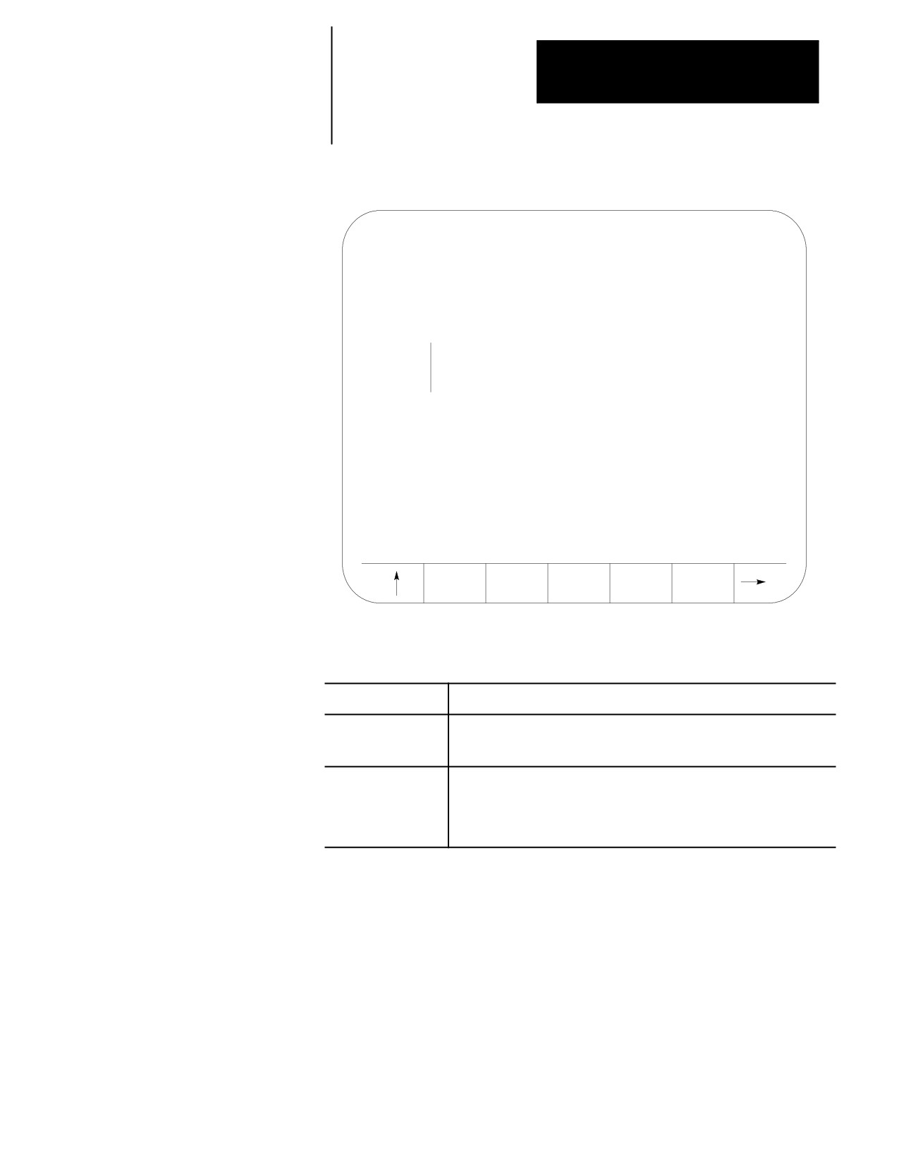
Press the {TOOL DIR} softkey. The control displays the current tool
directory screen showing all of the current tools and the groups that
they have been assigned to (see the following figure). The control
displays the prompt “EDIT GROUP:”.
(softkey level 3)
TOOL
TOOL
BACKUP
DIR
DATA
DATA
20-16
Chapter 20
Tool Control Functions
Figure 20.2
Typical Tool Group Directory Screen
ENTRY GROUP NO:
TOOL GROUP DIRECTORY
PAGE 1 0F 1
(FILE NAME)
GROUP
TOOL NUMBER
1
1
2
44
88
2
55
63
90
99
EDIT
DELETE
DELETE
GROUP
GROUP
ALL
At this point, you can delete any or all tool groups that already exist for
some reason follow these steps:
To delete:
Press:
select tool group
the {DELETE GROUP} softkey. Key in the desired group number to delete
and press the [TRANSMIT] key. This deletes all information in the tool group
including the tool offset numbers, threshold rate, tool numbers, etc.
all of the tool groups
the {DELETE ALL} softkey. The control prompts “DELETE ALL TOOL
MANAGEMENT DATA? (Y/N):”. Entering “Y”deletes all tool management
data that has been entered into the management tables (this does not delete
any G10 programs that are backups or used to set the tool management
tables). Entering “N”aborts the delete operation.
4.
Key in the group number that is to be edited. When you select the
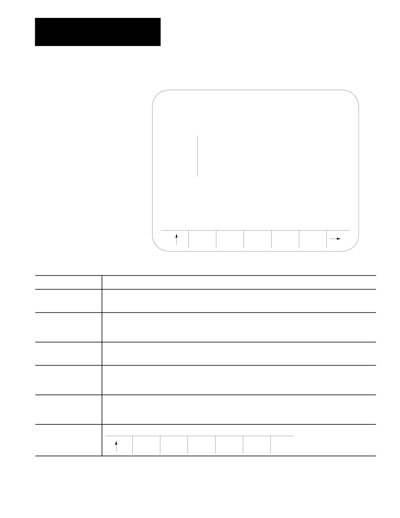
correct group, press the [EDIT GROUP] key. Figure 20.3 shows all
of the information for that tool group that is displayed.
20-17
Chapter 20
Tool Control Functions
Figure 20.3
Typical Tool Group Data Screen
ENTER DATA:
EDIT TOOL GROUP 1
PAGE
1 OF 1
(FILE NAME)
THRESHOLD RATE =80%
ENTRY
TOOL NUMBER
LIFE TYPE = TIME
NO
OFF NO
1
2
2
4
3
6
4
8
CHANGE
INSERT
DELETE
CHANGE
CHANGE
TOOL
TOOL
TOOL
TYPE
T RATE
5.
From this screen, you can:
Operation:
Description:
Change tools
Alter one of the tool numbers that has already been entered in the group. Move the cursor to the tool number to be changed
by pressing the up or down cursor keys (move the cursor full pages by holding down the shift key while pressing a cursor
key). Press the {CHANGE TOOL} softkey. Key in the new tool number and press the [TRANSMIT] key.
Insert tools
Insert a new tool number for that group. Move the cursor to the location to insert a new tool number at by pressing the up or
down cursor keys (move the cursor full pages by holding down the shift key while pressing a cursor key). Press the
{INSERT TOOL} softkey. Key in the new tool number and press the [TRANSMIT] key. The actual range of allowable tool
numbers is 1 to 9999.
Delete tool
Remove a tool number from that group. Move the cursor to the tool number to be removed by pressing the up or down
cursor keys (move the cursor full pages by holding down the shift key while pressing a cursor key). Press the {DELETE
TOOL} softkey. Respond yes or no and press [TRANSMIT].
Change life type
Alter how the control records and measures tool life for that group. Press the {CHANGE TYPE} softkey. The prompt “LIFE
TYPE...”is displayed on line 2 of the CRT. The same life type is assigned to all tools in any one tool group. Key in the
number of the desired tool life measurement type for that group and press the [TRANSMIT] key. 0 for “time,”1 for “number of
tool uses,”and 2 for “distance.”
Change life threshold rate
Alter the percentage of a tool’s expected life so that a tool is labeled as old. This percentage applies to all tools in the
selected group. To alter the threshold percentage (the percentage of total tool life that has been used before a tool will be
classified as old) press the {CHANGE T RATE} softkey. Key in the percentage of the total tool’s life so that the tool is
classified as old and press the [TRANSMIT] key. Tool life threshold rate is explained earlier in this section.
Change Color
(softkey level 4)
EDT LN
EDT CT
EDIT
RENEW
SCROLL
OF #
COMP #
LIFE
TOOL
COLOR
The application of these operations was described in detail earlier in this
section. All of this information can be entered into the tool groups using
the programming method described on page 20-22 .
20-18
Chapter 20
Tool Control Functions
20.4.2
This section assumes that tools have already been assigned to their specific
groups. This section describes specific information that is to be entered
Assigning Detailed Tool
into the tool life management tables for the individual tools. This
Data
information may also be entered into the tool management tables using the
programming method described on page 20-22. This information includes:
Tool length offset number
Tool diameter/radius offset number
Expected life of a tool
Tool length and diameter/radius offset number
Use this feature of tool life management so the programmer does not need
to know what tool has been called by tool life management and still have
the correct tool offsets and cutter compensation activated.
Important: The control only automatically enters the tool length and
cutter compensation offset numbers. This may or may not activate the tool
length offset or cutter compensation features. These features must still be
activated as normal.
Expected Tool Life
Use this feature of tool life management to set the expected life of a tool.
The type of tool measurement used is assigned to the tool group as
described in section 20.5.1. This tool measurement type determines the
units that are used for the expected tool life.
As a tool is used the amount of usage is recorded and displayed as the
accumulated tool life (the amount of the expected tool life that has been
used). This is displayed individually for each tool on the tool data display
screen. The accumulated tool life can be reset to zero by pressing the
{RENEW TOOL} softkey.
The following is a description of the units that should be entered for the
different tool life measurement types:
If tool life is measured in units of time (0 is selected as tool life type),
then the units for the expected tool life is minutes. Enter the minutes of
operation that the tool is expected to operate and still be within the
tolerance required for the part being cut. The accumulated life of a tool
is only measured when that tool is the active tool, and it is performing a
cutting operation. Moves that are rapid, or blocks that do not produce
axis motion are not added to the accumulated tool life.
20-19
Chapter 20
Tool Control Functions
If tool life is measured by the number of uses (1 is selected as tool life
type), then the units for the expected tool is the number of programs that
the tool may be selected as an active tool in. The accumulated life of a
tool is increased by one if that tool is selected in a program as the active
tool. Remember that the same tool may be active more than once in a
program, however its accumulated life only increments by one. Enter
the total number of program executions that can use the tool before the
tool no longer meets the required tolerance for the part being cut.
If tool life is measured in units of distance (2 is selected as tool life
type), then the units for the expected tool life is either inches or
millimeters (depending on the current operating mode of the tool).
Enter the distance of travel that the tool is expected to cut and still be
within the tolerance required for the part being cut. The accumulated
life of a tool is only measured when that tool is the active tool, and it is
performing a cutting operation. Moves that are are rapid, or blocks that
do not produce axis motion are not added to the accumulated tool life.
For multi-axis moves (including arcs and helices) the distance added to
the accumulated life is the vectorial distance, not necessarily the
distance traveled on each axes.
During turning cycles only the distance that the tool travels along the
workpiece contour is added to the accumulated life. The other three
moves of the cycle are not added regardless of if they are executed at
cutting speed. The entire finishing pass for the contouring routine (if
any) is used to increase the accumulated tool life.
Entering Specific Tool Data
The following steps describe the method of entering specific tool data for
tool management. This includes tool offset numbers, and expected tool
life:
Important: This section assumes that the steps required to assign tools to
specific groups has been performed as described in section 20.5.1.
1.
Press the {OFFSET} softkey.
(softkey level 1)
PRGRAM
OFFSET
MACRO
PRGRAM
SYSTEM
MANAGE
PARAM
CHECK
SUPORT
FRONT
ERROR
PASS-
SWITCH
PANEL
MESAGE
WORD
LANG
20-20
Chapter 20
Tool Control Functions
2.
Press the {TOOL MANAGE} softkey.
(softkey level 2)
WORK
TOOL
TOOL
TOOL
RANDOM
CO-ORD
WEAR
GEOMET
MANAGE
TOOL
COORD
BACKUP
SCALNG
ROTATE
OFFSET
3.
Press the {TOOL DATA} softkey. The control displays the prompt
“EDIT GROUP:”.
(softkey level3)
TOOL
TOOL
BACKUP
DIR
DATA
DATA
4.
Key in the group number to edit using the keys on the operator panel
and press the [TRANSMIT] key. Figure 20.4 shows all of the
information for that tool group that is displayed.
Figure 20.4
Typical Tool Data Screen
ENTER DATA=
GROUP
1
DATA
TYPE=TIME
PAGE
1 OF 1
(FILE NAME)
THRESHOLD RATE
=
80%
TOOL
T.LEN
CUTTER
EXPECT
ACCUM
TOOL
NO
OFF NO
CMP NO
LIFE
LIFE
STATUS
1
2
3
100
100
EXPIRED
12
20
57
100
95
OLD
23
40
95
100
0
EDT LN
EDT CT
EDIT
RENEW
SCROOL
OFF #
COMP #
LIFE
TOOL
COLOR
20-21
Chapter 20
Tool Control Functions
5.
From this screen it is possible to perform the following operations.
The application of these operations was described in detail earlier in
this section.
Operation:
Description:
Enter or alter the tool
To enter or alter a value for the tool length offset number, move the cursor
length offset number
to the tool number of the tool to alter and press the {EDIT LN OFF}
softkey. Key in the new offset number that calls the correct data from the
offset tables for that tool for its tool length offset number and press the
[TRANSMIT] key. The old value for tool length (if any) is discarded and
the new value replaces it.
Enter or alter the tool
To enter or alter a value for the tool radius offset number, move the cursor
radius offset number
to the tool number of the tool to alter and press the {EDIT CT CMP}
softkey. Key in the new offset number that calls the correct data from the
offset tables for that tool for it’s radius and press the [TRANSMIT] key.
The old value for radius offset numbers (if any) is discarded and the new
value replaces it.
Enter or alter the
To enter or alter a value for the expected life of a tool, move the cursor to
expected life of a tool
the tool number of the tool to alter and press the {EDIT LIFE} softkey.
Key in the new expected life of the tool (in units as determined by the tool
life type) and press the [TRANSMIT] key. The old value for expected life
(if any) is discarded and the new value replaces it.
Reset the accumulated
To reset the accumulated tool life to zero, move the cursor to the tool
tool life to zero
number of the tool to alter and press the {RENEW TOOL} softkey. The
old accumulated life of the tool is discarded and a value of zero is entered
as the new accumulated tool life. This is normally performed after an old
or expired tool has been replaced with a new tool. This updates the
status of the tool and remove any “OLD,”or “EXPIRED”status.
Change color used to
Each tool group may be assigned its own tool color. To change the color
graph the tool selected
selected for a tool on the CRT press the {SCROL COLOR} softkey. This
on the CRT for color
alters tool color for the current tool when tool paths are displayed in either
systems
quick check graphics, or active tool path graphics.
(softkey level 4)
EDT LNEDT CT
EDIT
RENEW
SCROL
OFF #
COMP #
LIFE
TOOL
COLOR
20.4.3
This feature allows the rapid loading of information into the tool
Programming Data and
management tables. This is done by executing a program that
automatically loads the tool management tables. This program can also be
Backing Up Tool
generated automatically when the tool management tables are backed up as
Management Tables (G10L3,
described later in this section.
G11)
Data is sent to the tool management tables when the control executes this
G10 block:
G10L3;
This block indicates to the control that any information following this
block is to be used to set the tool management tables.
20-22
Chapter 20
Tool Control Functions
Important: G10 blocks may not be programmed when TTRC is active.
CAUTION: Any time that a G10L3; block is executed the
control automatically clears all information that is in the
management tables for all tools and tool groups.
Any time after the G10L3 command, parameters may be programmed to
enter what tool group is being entered, the type of tool life measurement
that is being used, and the tool life threshold percentage. The format for
this block is:
P__I__Q__;
Where :
Is :
P__
The value entered with the P-word is used to program what tool group number is
being edited. The following blocks assign tools to that tool group.
I__
The value entered with the I-word is used to program the type of tool life
measurement that is to be used for all the tools in that group. I0 sets a type of
time, I1 sets a type of number of uses, and I2 sets a type of distance. See
section 20.5.1 for details. If more than one I-word is programmed for a tool group
the control uses the last programmed I-word for that group. If no I-word is
programmed for a group the control uses I1 as a default value.
Q__
The value entered with the Q-word is used to program the threshold percentage
for that tool group. Enter the percentage of the total expected tool life that
causes the tools in the group to be classified as old. See section 20.5.1 for
details on threshold percentage. If the Q-word is not programmed in a block the
control uses a default value of 80%. If more than one Q-word is programmed for
a tool group the control uses the last programmed Q-word for that group. If no
Q-word is programmed for a tool group the control uses Q80 as the default value.
20-23

Chapter 20
Tool Control Functions
The following program blocks assign tools to groups, length and cutter
compensation offset numbers, and expected tool life to specific tools. This
information is assigned to the last group number programmed in a block
using the P-word. The format for these blocks is:
T__ H__ D__ L__;
Where :
Is :
T__
The value entered with the T-word is the tool number of the tool to be assigned to
that group.
H__
The value entered with the H-word is the tool length offset number from the tool
geometry and wear tables that is to be assigned to this tool. The H-word is only
valid if programmed in the same block as a T-word.
D__
The value entered with the D-word is the tool radius number from the tool
geometry and wear tables that is to be assigned to this tool. The D-word is only
valid if programmed in the same block as a D-word.
L__
The value entered with the L-word is used to program the value of the expected
tool life for that tool. The controls interpretation of this is dependant on the value
set with the I-word in this program block. The value programmed with the L-word
remains active for all following tools in that group until replaced with a different
L-word, or a new tool group is programmed with a P-word.
All of the tools should then be programmed for that group in individual
blocks. When all of the tools for that group have been entered, change
groups by programming a different P-word in a block.
When all of the tools for all of the different groups have been entered, end
the execution of editing the tool life management table by programming
either a M02 or M30 end of program blocks or by entering this block:
G11;
This cancels the G10 data setting mode for tool management.
Important: Any information that was contained for a specific tool group
that has been written to using a G10L3 command as described above is
overwritten by the information programmed with the G10 blocks. All
previous data for tool management for any of the groups is lost.
20-24