9/Series CNC Lathe. Operation and Programming Manual - page 17

Chapter 20
Tool Control Functions
Example 20.6
Programming Tool Life Management Data
Program Block
Description
G10L3;
Starts loading tables.
P1I1Q60;
Begins loading data for tool group 1. Type 1 (number of uses)
measurement. Threshold 60%.
T1H5D7L25;
Places tool 1 in group 1 with length offset number of 5, cutter
radius offset number 7, and expected life of 25 uses.
T2H2;
Places tool 2 in group 1 with length offset number of 2, no
cutter radius offset number and expected life of 25 uses.
T15H7;
Places tool 15 in group 1 with length offset number of 7, no
cutter radius offset number and expected life of 25 uses.
P2;
Begins loading data for tool group 2. Type 0 measurement
(default). Threshold at 80% (default).
T12H3D6L40;
Places tool 12 in group 2 with length offset number of 3, cutter
radius offset number of 6, and expected life of 40 minutes.
T13;
Places tool 13 in group 2 with length and radius offset numbers
of 0 and expected life of 40 minutes.
P4I0Q90;
Begins loading data for tool group 4. Type 0 (time)
measurement. Threshold at 90%.
T20H3D6;
Places tool 20 in group 4 with length offset number of 3, cutter
radius offset number of 6, and expected life of 0 minutes.
Q50;
Resets the threshold at 50% for group 4.
G11;
Ends the loading operation.
M02;
Backing up tool management tables
This feature causes the control to automatically generate a G10L3 program
that stores all of the information that it finds in the current tool
management table. Any time that this G10 program is executed, it clears
any information that is currently in the management tables and replaces it
with the information that is in the G10 program.
To generate the G10L3 backup program of the tool management tables,
follow these steps:
1.
Press the {OFFSET} softkey.
(softkey level 1)
PRGRAM
OFFSET
MACRO
PRGRAM
SYSTEM
MANAGE
PARAM
CHECK
SUPORT
FRONT
ERROR
PASS-
SWITCH
PANEL
MESAGE
WORD
LANG
20-25
Chapter 20
Tool Control Functions
2.
Press the {TOOL MANAGE} softkey.
(softkey level 2)
WORK
TOOL
TOOL
TOOL
RANDOM
CO-ORD
WEAR
GEOMET
MANAGE
TOOL
COORD
BACKUP
SCALNG
ROTATE
OFFSET
3.
Press the {BACKUP DATA} softkey. The prompt “BACKUP
FILENAME:” is displayed on the input line.
(softkey level 3)
TOOL
TOOL
BACKUP
DIR
DATA
DATA
4.
Key in any legal program name and press the [TRANSMIT] key.
This program name is used as the program that stores all of the
backed up tool management data. The control generates the tool
management G10 program.
20.4.4
This section describes how to activate a tool using tool life management.
Programming a T-word
When using tool life management, remember:
Using Tool Management
Your system installer sets up a boundary for T-words used with tool life
management in AMP. Any T-word programmed that calls a tool number
less than, or equal to, this boundary is used as a normal tool number.
Any T-word programmed that calls a tool number greater than this
boundary is used as a tool group number for tool management.
When a T-word is programmed using tool life management, the group
that is called with the T-word is equal to the programmed T-word, minus
the value of the boundary set in AMP by your system installer. This
boundary does not include any offset number normally attached to the
T-word. Place holder digits for tool offsets must be programmed,
although their values are ignored. See Example 20.7.
Your system installer must have altered AMP parameters from their
default condition to use tool management. The default condition sets a
tool boundary at 100 and a T-word format of 3 digit geometry + wear.
This default configuration requires a minimum six digit T-word be
programmed to activate any tool group in tool life management. This
configuration does not work if the AMP parameter maximum
allowable T-word remains set to its default of only 5 digits.
20-26
Chapter 20
Tool Control Functions
Example 20.7
Assume your system installer has set the following constraints in AMP:
- the tool group boundary is set as 100
- the T-word format is configured as 2-digit geometry and wear (see
section 20.1)
- the maximum allowable T-word is configured as a 5-digit number
To use tool management program for these constraints:
Ttttoo;
Where :
Is :
Tttt
-- -- the group number (if greater than the group boundary)
-- -- a tool number (if less than the group boundary)
oo
the place holder for the tool offset number
Table 20.B
Result of Different T-words for Example 20.7
T-word
Result
T12;
Since tool number is below boundary and two digits are necessary for offset with
this T-word format, no tool is programmed here. Instead tool geometry and tool
wear offset number 12 is selected.
T1201;
Tool 12 and geometry and wear offset number 1 is selected. Tool life management
is not used because tool number 12 is below the group boundary of 100.
T10100;
The first available tool assigned to group 1 is selected along with the offset numbers
assigned to that tool in the tool management table.
T10201;
The first available tool assigned to group 2 is selected along with the offset numbers
assigned to that tool in the tool management table. The geometry and wear offset
number of 01 programmed here is ignored.
T123456;
Error occurs because maximum allowable T-word of 5 digits has been exceeded.
20-27
Chapter 20
Tool Control Functions
Example 20.8
Programming Tool Changes Using Tool Life Management.
Example 20.8 assumes that:
- your system installer has configured in AMP the boundary for tool
life management at 100
- the tool changer is located at the secondary machine home point
called by a G30; this is not necessarily true for different machine
applications
- the T-word format is configured as 3 digit geometry + wear
- the maximum allowable T-word format has been set to allow 6-digit
T-words.
Program Block
Description
G30X10Z10F.1;
Return to secondary home position.
T101000;
Change to a group 1 tool.
G29;
Return from secondary home position. Activate tool length
offset using the offset number for the tool as assigned in the
tool management table.
G42;
Activate TTRC right using the offset number for the tool as
assigned in the tool management table.
END OF CHAPTER
20-28

Chapter
21
Tool Tip Radius Compensation (TTRC)
Function
21.0
This chapter describes Tool Tip Radius Compensation function. Major
topics include:
Chapter Overview
Topic:
On page:
Programming TTRC
21-4
Generation blocks
21-8
Tool paths (Type A)
21-10
Tool paths (Type B)
21-20
Tool path during TTRC
21-30
Special cases
21-35
Error detection
21-52
Generally, cutting tools used on lathes have a rounded cutting edge which
often results in a difference between the cutting tool tip position assumed
in writing a part program, and the actual cutting tool tip position. This
inevitably causes a difference between the programmed shape and the
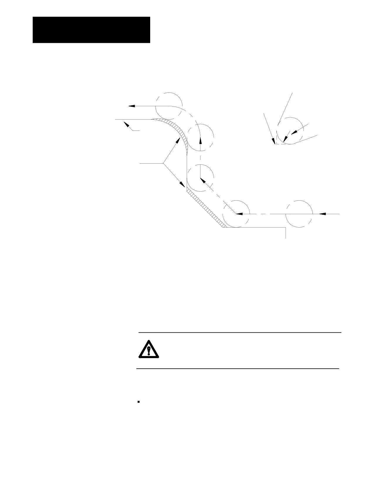
actual shape cut on the workpiece in taper and arc cutting operations. See
Figure 21.1.
For reference, the term “tool tip radius compensation” has been shortened
to TTRC and is referred to as such in the following sections.
The TTRC functions allows you to use tools with different radii without
requiring a modification of the part program.
21-1
Chapter 21
Tool Tip Radius Compensation (TTRC)
Function
Figure 21.1
Taper and Arc Cutting Without TTRC
Without TTRC active,
control assumes tool
has a perfect point
Cutting
tool
Actual tool
tip radius
Part
profile
Material left uncut
due to radius of
tool tip
Put the radius of the tool and tool orientation data into the offset tables in
advance. This function lets the control use the same program to produce
the same workpiece, regardless of the radius of the tool that does the
cutting.
This feature also uses tool orientation data taken from the tool geometry
table. You need this tool orientation to compensate for inaccuracies that
can occur from difficulties in measuring tool tip diameter because of a tool
mounting position. If this is not a factor, make sure all tool orientations
use an orientation of either 0 or 9.
CAUTION: If you use a 2-turret lathe, be aware that the X tool
offset and the tool orientation values will be opposite of the A
turret values for the second mirrored (B).
We use these terms in this section:
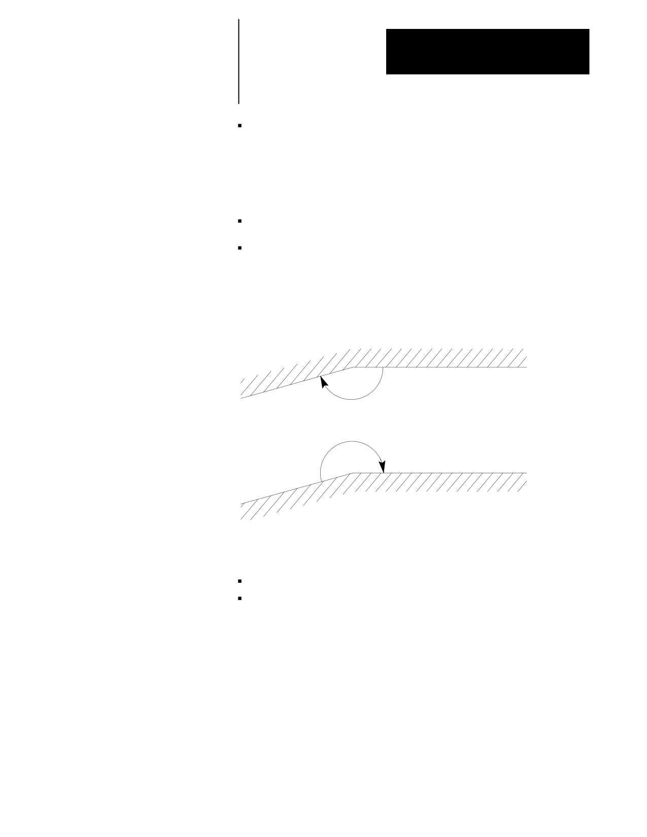
inside ---- Refer to an angle between two intersecting programmed tool
paths as inside if, in the direction of travel, the angle measured
clockwise from the second tool path into the first is less than or equal
to 180°. See Figure 21.2. If one or both of the moves are circular, the
angle is measured from a line tangent to the tool path at their point of
intersection.
21-2
Chapter 21
Tool Tip Radius Compensation (TTRC)
Function
outside ---- Refer to an angle between two intersecting programmed tool
paths outside if, in the direction of travel, the angle measured clockwise
from the second tool path into the first is greater than 180°. See
Figure 21.2. If one or both of the moves are circular, the angle is
measured from a line tangent to the tool path at their point of
intersection.
r ---- cutter radius
CR ---- cross-point between two programmed paths after you activate the
TTRC
Figure 21.2
Definition of Inside and Outside
workpiece
Inside angle (less than 180°)
Outside angle (greater than 180°)
workpiece
There are two types of cutter compensation available on the 9/Series
control:
type A (as described on page 21-10)
type B (as described on page 21-20)
21-3
Chapter 21
Tool Tip Radius Compensation (TTRC)
Function
This table highlights the differences between the two types:
Type of Move
Type A
Type B
Entry Move Into
-- The tool takes the shortest possible
-- The tool stays at least one radius away
TTRC
path to its offset position.
from the start-point of the next block at
all times.
-- Extra motion blocks can be generated
to attempt to prevent gouging of the
part as may occur in Type A.
Tool
-- Same as Type B.
-- Same as Type A.
Path
Exit Move From
-- The tool takes the shortest path to the
-- The tool takes the shortest path to the
TTRC
end-point of the exit move for both
end-point of exit move for inside
inside and outside corners.
corners only.
-- For outside corners, the tool stays at
least one radius away from the
end-point.
Your system installer determines whether to use type A or type B by a
control in AMP.
21.1
These G-codes are used for TTRC:
Programming TTRC
G-code:
TTRC, :
G41
left
G42
right
G40
cancel
Left or right is defined as offsetting the tool to the left or right of the
programmed cutting path when facing the direction of cutter motion.
Important: If you set a negative value in the offset tables as the tool
radius, this reverses compensation direction (tool left or right) for the G41
and G42 codes. G41 and G42 are also reversed during the mirroring
operation. See chapter 14.
All of these G-codes are modal and belong to the same modal group.
21-4
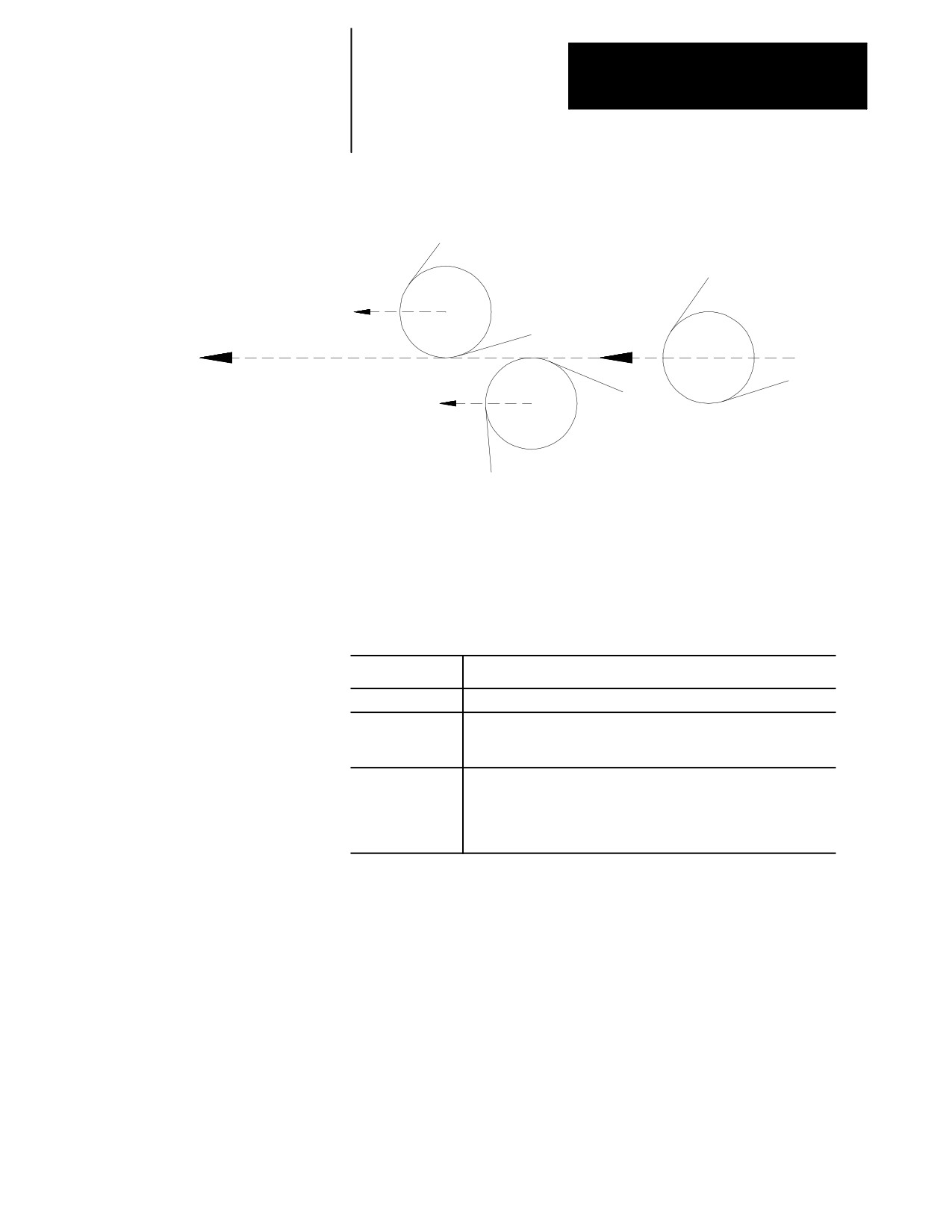
Chapter 21
Tool Tip Radius Compensation (TTRC)
Function
Figure 21.3
TTRC Direction
G42; Compensation
right
G40; Compensation
cancel
Programmed tool path
and direction
G41; Compensation
left
Important: The TTRC function is not available during any of the thread
cutting cycles. TTRC must be canceled before any threading routine can
be performed.
Program the TTRC function with this format:
G41(or G42)X ___ Z ___ T ___ ;
Where :
Is :
G41(or G42)
TTRC direction, G41=left, G42=right
X, Z
End-point of entry move into TTRC. Program an entry move only on
axes in the currently active plane. Axis motion must take place in
order for TTRC to be active on an axis.
T
Designates the offset numbers and pulls data: 1) from the wear and
geometry tables for the tool radius, and 2) from the geometry table for
tool orientation. See chapter 20 for information on programming a
T-word. The T-word is optional in the G41 or G42 blocks. The T-word
may also be designated in any previous or following program block.
21-5
Chapter 21
Tool Tip Radius Compensation (TTRC)
Function
You can program TTRC in various ways. Example 21.1 shows 1-, 2-, and
3-block programs activating TTRC with entry moves.
Example 21.1
Initializing TTRC
Assume: G18 (ZX Plane Selection)
Program Block
Comment
One Block
G42 T0016 X1 Z1;
Sets compensation right, selects tool
radius offset number, and activates move to
X1 Z1
Two Blocks
T0016;
Selects tool radius offset number
G42 X1 Z1;
Sets compensation right and activates move
to X1 Z1
Three Blocks
T0016;
Selects tool radius offset number
G42;
Sets compensation right
X1 Z1;
Activates move to X1 Z1
Important: Any entry move (see page 21-10 and 21-20) into TTRC must
be a linear move. You cannot initially activate TTRC by programming
either the G41 or G42 commands in a circular cutting mode (G02 or G03).
However, if TTRC is already active, the G41 or G42 commands can be
programmed in a circular block to change TTRC direction either left (G41)
or right (G42).
The T-word calls this data from the offset tables:
Initial cutter radius data (from geometry table)
Cutter radius wear data (from wear table)
Tool orientation data (from geometry table)
The control uses the sum of the cutter radius data from the geometry and
wear tables as the data for the tool tip radius. The orientation data is used
when determining tool positioning information relative to the part.
The designation of the T-word can be done in any block before the
designation of the G42 or G41 commands or in any following block that
contains axis motion in the plane selected for compensation. This is also
provided that doing so will not generate the initialization of TTRC. If
TTRC is initialized in the block containing a T-word, it must be a linear
block.
Important: A T-word also calls up data from the geometry and wear tables
for the tool length offset function described in chapter 20.
21-6
Chapter 21
Tool Tip Radius Compensation (TTRC)
Function
Important: The TTRC feature is not available for any motion blocks that
are programmed in MDI mode. See page 21-30. The TTRC mode can be
altered by programming either G41, G42, or G40, or the tool radius can be
changed in an MDI program. However, none of the tool paths executed in
MDI will be compensated. Any changes made to TTRC are not applied
until the next block executed in automatic mode.
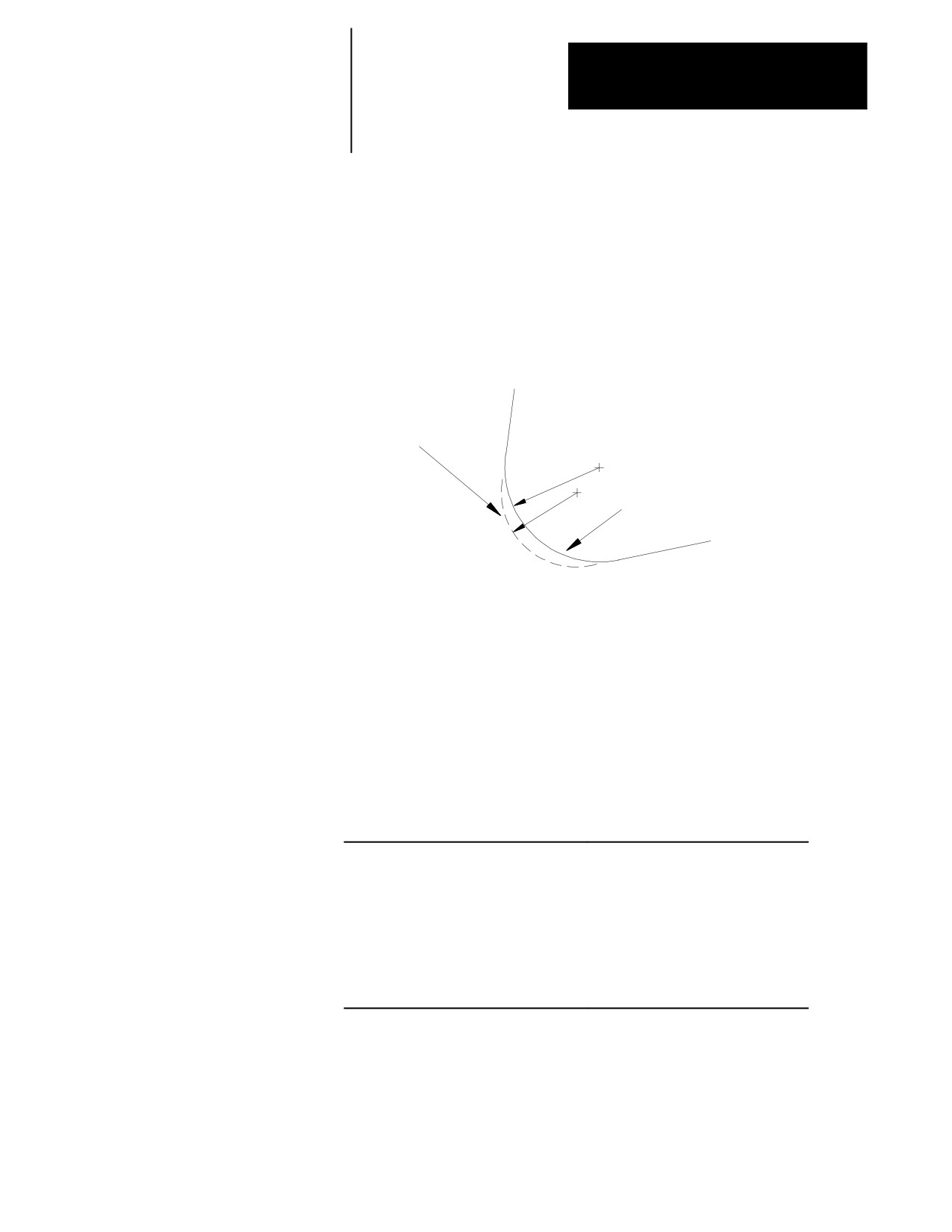
Figure 21.4
Tool Radius Wear
WEAR = R’- R
Cutting edge before
tool wear
R’
Worn cutting
R
edge
G40 (TTRC cancel) is active when power is turned on, when E-STOP is
reset, when the control is reset, or when an M02 or M30 end-of-program
block is executed.
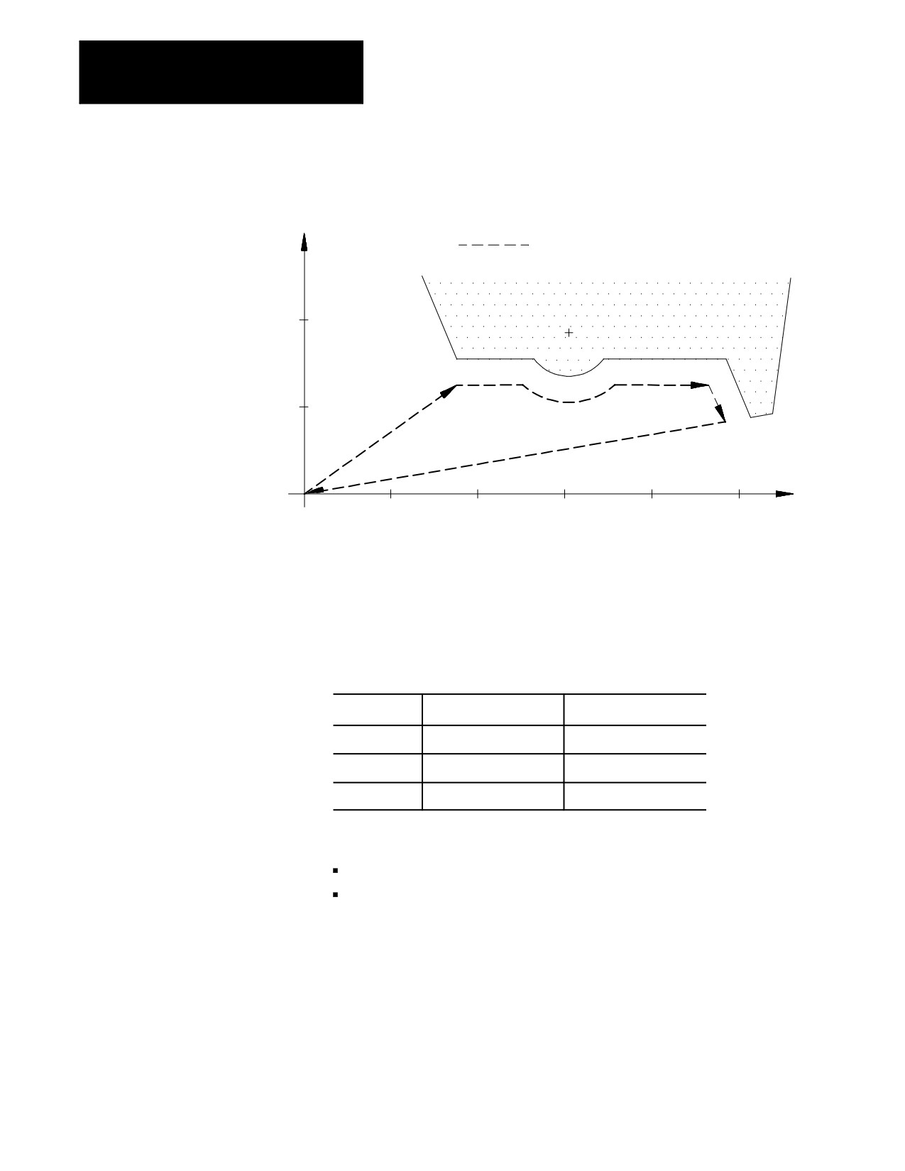
Example 21.2
Tool Tip Radius Compensation Sample Path
Assume: T01 = 5mm tool radius total from both geometry and wear tables.
Also assume a tool orientation of 0.
Program Block
Comment
N1G00G42X30.Z35.T01;
rapid to start and set TTRC right
N2G01Z52.F.1.;
feed move to Z52
N3G03Z68.R15.;
arc of radius 15
N4G01.Z95.;
feed move to Z95
N5Z102.X18.;
feed move to Z102 X18
N6G40X0Z0;
exit TTRC
N7 M30
end of program
21-7
Chapter 21
Tool Tip Radius Compensation (TTRC)
Function
Figure 21.5
Results of TTRC Program Example
Cutting tool center path
X
N2
N4
N3
N5
N1
N6
start
Z
point
21.2
In certain instances, TTRC creates a non-programmed move called a
TTRC Generation Blocks
generated block. These blocks improve cycle time and corner-cutting
quality.
G39, G39.1
TTRC generates blocks for type A or B moves as follows:
Type of Move
Type A
Type B
Entry Move
No block is generated
Block is generated
Tool Path
Block is generated
Block is generated
Exit Move
No block is generated
Block is generated
Important: These blocks are created only if:
G41 is active and cutting an inside angle that is less than 90°
G42 is active and cutting an outside angle that is more than 270°
21-8
Chapter 21
Tool Tip Radius Compensation (TTRC)
Function
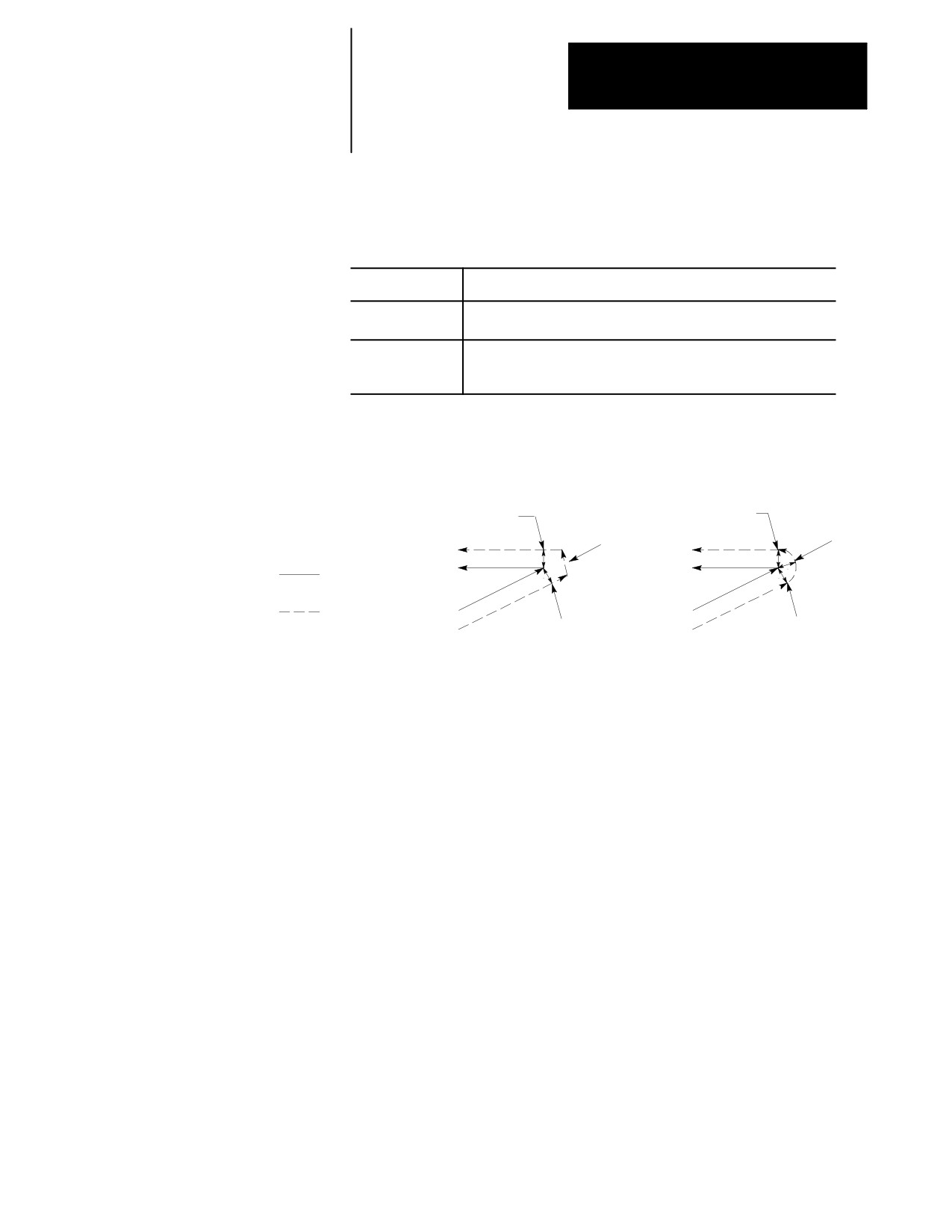
The generated block between the two tool paths can be programmed as
linear or circular with these G-codes:
G39(or G39.1);
Where :
Causes:
G39
linear transition blocks. If neither G39 or G39.1 is programmed, G39
is the default. This command is modal.
G39.1
circular transition blocks. When cutting straight line-to-arc or
arc-to-straight line moves, the generated block will always be linear,
and the G39.1 will be ignored. This command is modal.
Figure 21.6
TTRC Generated Blocks (G39 vs G39.1)
G39 (Linear generated block)
G39.1 (Circular generated block)
Start of
Linear
Start of
Circular
2nd cut
generated
2nd cut
generated
block
block
r
r
r
Programmed
r
r r
path
r
G42 Tool path
End of
End of
r
= Tool radius
1st cut
1st cut
G39 or G39.1 can be programmed in any block. However, they must be
programmed in or before the block that causes a TTRC generated block.
Important: For linear generated blocks, your system installer can define a
minimum block length in AMP. If the generated move length is less than
the system-defined minimum block length, no generated block is created.
The tool path proceeds to the intersection of the two compensated paths. If
the generated move length is equal to, or greater than, the system-defined
minimum block length, a generated block is created.
Throughout this chapter, we show drawings where a generated block is
created. Both G39 and G39.1 are shown in these drawings where
applicable.
21-9
Chapter 21
Tool Tip Radius Compensation (TTRC)
Function
21.3
The easiest way to demonstrate the cutting tool’s the actual tool paths when
using TTRC type A is by pictorial representation. The following
TTRC Tool Paths (Type A)
subsections describe the cutter path along with a figure to clarify the
description
21.3.1
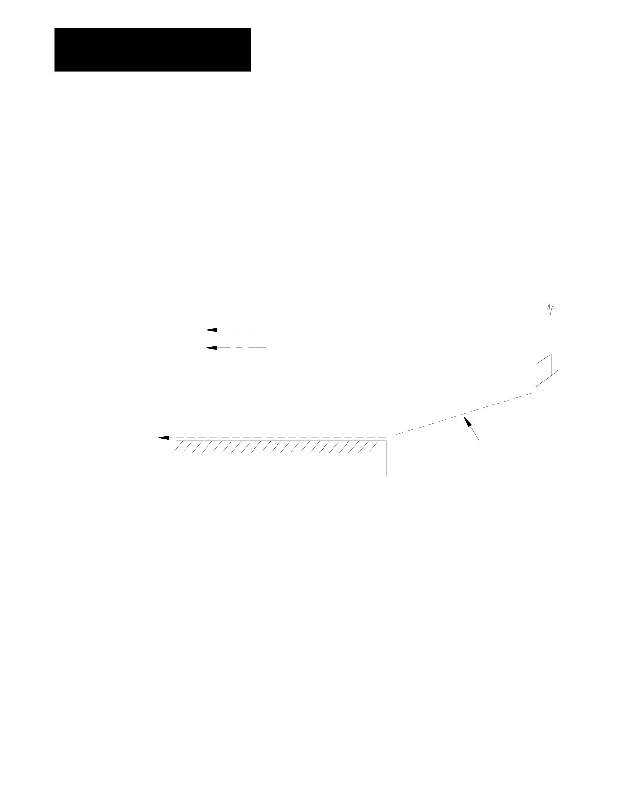
An entry move is defined as the path that the cutting tool takes when the
TTRC Type A Entry Moves
TTRC function first becomes activated in a program. Figure 21.7 shows a
typical entry move.
Figure 21.7
TTRC Entry Move
Programmed tool path
Cutting tool center path
Cutting tool
G42 TTRC right
Compensation entry move
Workpiece
Important: Any entry move into TTRC must be a linear move. Initial
activation of TTRC by designation of either the G41, G42, or T-word that
initializes TTRC in a circular cutting mode (G02 or G03) is not allowed.
The G41, G42, or T-word can be designated in a circular block to change
TTRC direction or tool radius, as long as TTRC is already active.
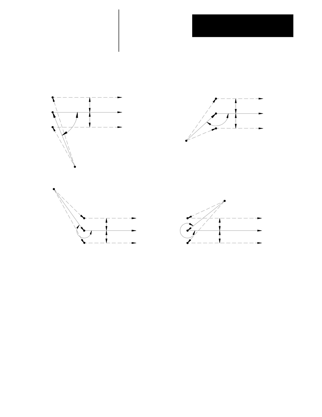
The entry move of the cutting tool for type A TTRC takes the shortest
possible path to its offset position. This position is at right angles to and
on the left or right side of the next programmed move in the currently
defined plane.
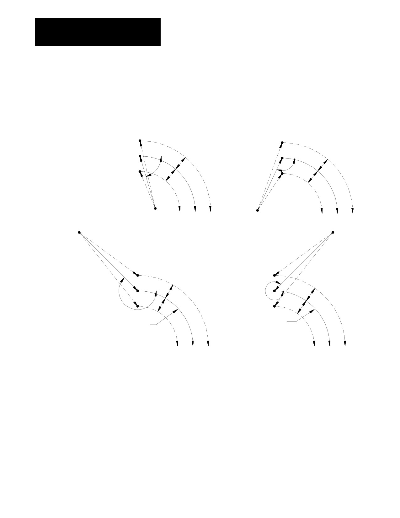
Figure 21.8 and Figure 21.9 show examples of typical entry moves using
type A TTRC.
21-10
Chapter 21
Tool Tip Radius Compensation (TTRC)
Function
Figure 21.8
Tool Path for Entry Move Straight Line-to-Straight Line
0
£q£90
90
£q£180
G41
G41
r
r
Programmed
Programmed
path
path
r
q
r
q
G42
G42
Start-point
Start-point
180
£q£270
270
£q£360
Start-point
Start-point
G41
G41
r
r
Programmed
Programmed
path
q
path
r
r
q
G42
G42
21-11
Chapter 21
Tool Tip Radius Compensation (TTRC)
Function
If the next programmed move is circular (an arc), position the tool at right
angles to a tangent line drawn from the start-point of that circular move.
Figure 21.9
Tool Path for Entry Move Straight Line-to-Arc
0
£q£90
90
£q£180
G41
G41
Programmed path
Programmed path
r
r
q
q
G42
r
r
G42
Start-point
Start-point
Start-point
Start-point
180
£q£270
270
£q£360
G41
G41
r
r
q
q
r
r
G42
G42
Programmed path
Programmed path
There is no limit to the number of blocks that can follow the programming
of G41 or G42 before an entry move takes place. The entry move will
always be the same regardless of the number of blocks that do not program
motion in the current plane for compensation.
21-12

Chapter 21
Tool Tip Radius Compensation (TTRC)
Function
Example 21.3
Sample Entry Move After Non-Motion Blocks
Assume current compensation plane is the ZX plane.
N01X0Z0;
N2G41T1;
This block commands compensation left
N3M02;
This is not the entry block since no axis motion takes place in
the current plane.
N4...;
No axis motion in current plane.
N5...;
No axis motion in current plane.
N6...;
No axis motion in current plane.
”
”
”
”
”
”
N999X1Z1;
This is the entry move for the previously programmed G41.
Your system installer selects in AMP the allowable number of non-motion
blocks that is to be allowed during TTRC before the entry move must be
re-initialized. See page 21-30.
For example, assume that your system installer has designated that only
two non-motion blocks can be performed. Then, if more than two blocks
following the entry move do not contain axis motion in the current plane,
the entry move is re-performed at the next block containing axis motion in
the current plane.
Example 21.4
Too Many Non-Motion Blocks After Entry Block
Assume current plane to be the ZX plane.
N1X0.Z0.;
N2G41T1X1.Z1.;
Entry move TTRC left.
N3;
No axis motion in current plane.
N4...;
No axis motion in current plane.
N5X4Z-4;
New entry move TTRC left.
21-13
Chapter 21
Tool Tip Radius Compensation (TTRC)
Function
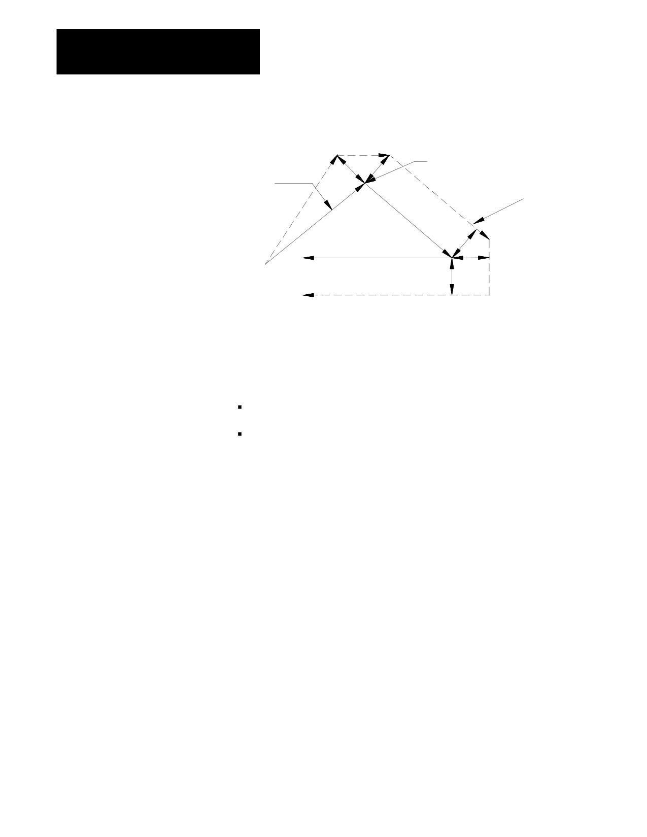
Figure 21.10
Results of Example 21.4
Too many non-motion
r
blocks here
Programmed
r
path
TTRC
reinitialized here
G41
r
r
r
21.3.2
Cancel the TTRC feature by programming G40. Refer to the path that is
TTRC Type A Exit Moves
taken when the tool leaves TTRC as the exit move. The path that the tool
follows during an exit move is dependant on:
The direction of compensation (G41 or G42).
The angle between the last motion made in TTRC (in the current
compensation plane) and the motion of the exit move.
Designating a tool offset number T00 in a program does not cancel TTRC
and does not generate an exit move. TTRC simply continues on as if a tool
radius had been changed to a radius of zero. See page 21-30 for
information about changing cutter radius. The exit move, if T00 is the
active tool radius, is the same path as the programmed tool path.
Important: An exit move cannot be a circular move (G02 or G03). Any
exit move must be programmed on a linear path. Any attempt to generate
an exit move by using a circular path generates a block-format error.
21-14
Chapter 21
Tool Tip Radius Compensation (TTRC)
Function
Example 21.5 gives some sample exit move program blocks.
Example 21.5
Type A Sample Exit Moves
Assume the current plane is the XZ plane and TTRC is already active
before the execution of block N100 in these program segments.
N100X1.Z1.;
N110X3.Z3.G40;
Exit move.
N100X1.Z1.;
N110G40;
N120X3.Z3.;
Exit move.
N100X1.Z1.;
N110G40;
N120;
No axis motion in the current plane.
N130...;
No axis motion in the current plane.
N140...;
No axis motion in the current plane.
”
”
”
”
N200X3.Z3.;
Exit move.
N100X1.Z1.;
N110...;
No axis motion in the current plane.
N120...;
No axis motion in the current plane.
N130...;
No axis motion in the current plane.
”
”
”
”
N200G40X3.Z3.;
Exit move.
All of the program blocks in Example 21.5 produce the same exit move
provided the number of non-motion blocks in the compensation mode has
not exceeded a value selected by your system installer in AMP.
The exit of the cutting tool for type A TTRC takes the shortest possible
path to the endpoint of the exit move. This path starts at right angles to the
left or right of the endpoint (depending on G41 or G42) of the last move in
the currently defined plane. You can redefine this start-point by using an I-
and/or K-word as described later in this section. The end-point of the exit
move is no longer offset to the left or right.
21-15
Chapter 21
Tool Tip Radius Compensation (TTRC)
Function
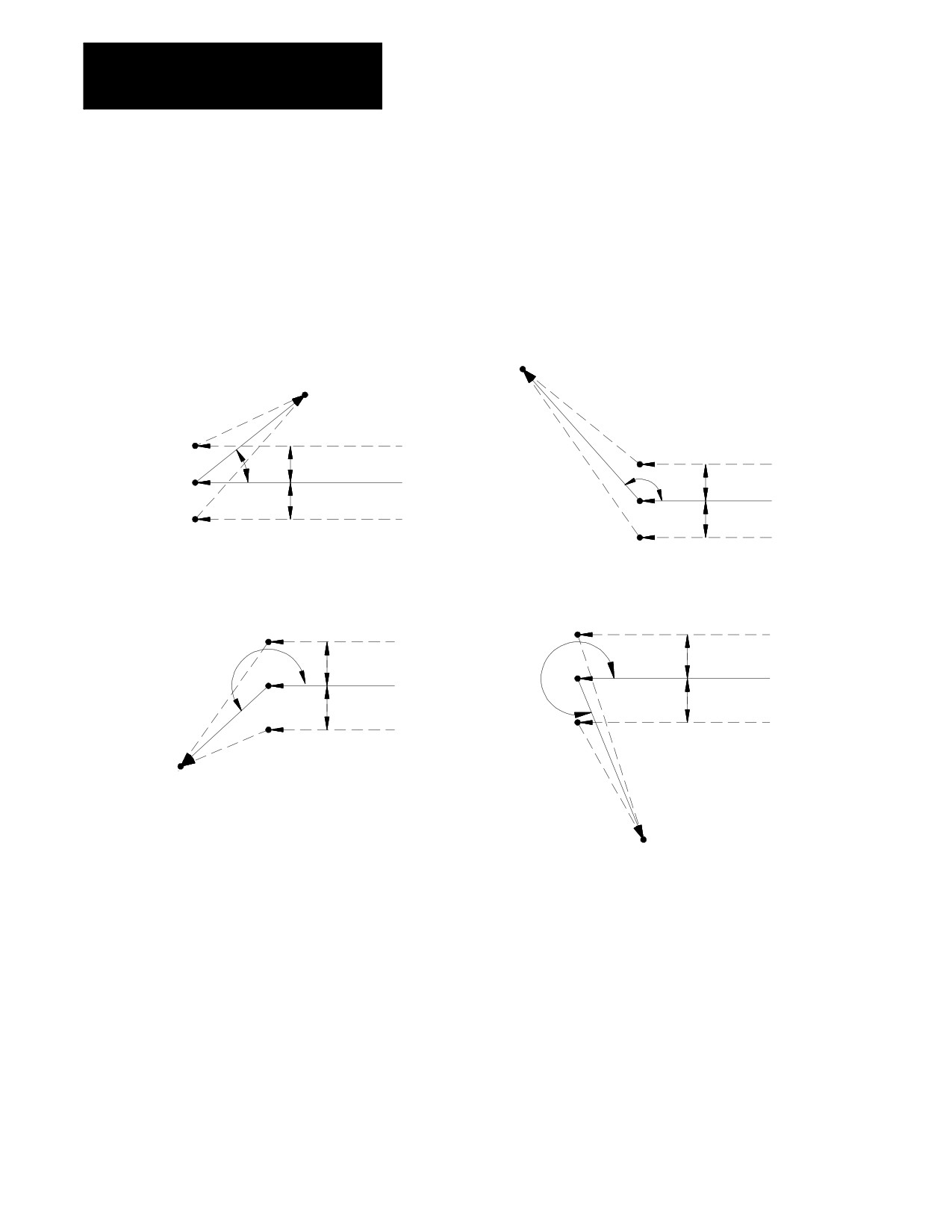
Figure 21.11 through Figure 21.15 show examples of typical exit moves
using type A TTRC. All examples assume that the number of non-motion
blocks before the designation of the G40 command have not exceeded the
number allowed as determined by your system installer in AMP.
Figure 21.11
Tool Path for Exit Move Straight Line-to-Straight Line
End-point
0
£q£90
0
£q£90
End-point
G42
r
G42
q
Programmed
r
q
r
path
Programmed
G41
r
path
G41
0
£q£90
0
£q£90
G42
G42
r
q
r
Programmed
Programmed
q
r
path
r
path
G41
G41
End-point
End-point
21-16
Chapter 21
Tool Tip Radius Compensation (TTRC)
Function
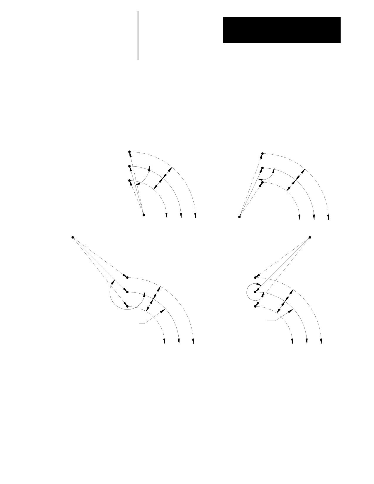
If the last programmed move is circular (an arc), positioning the tool at
right angles to a tangent line drawn from the end-point of that circular
move.
Figure 21.12
Tool Path for Exit Move Arc-to-Straight Line
0
£q£90
0
£q£90
G41
G41
Programmed path
Programmed path
r
r
q
q
G42
r
r
G42
Start-point
Start-point
Start-point
Start-point
0
£q£90
0
£q£90
G41
G41
r
r
q
q
r
r
G42
G42
Programmed path
Programmed path
The examples in Figure 21.11 and Figure 21.12 assume that the number of
blocks that do not contain axis motion, in the currently selected plane,
follow the G40 programming before an exit move takes place and does not
exceed an amount selected in AMP by your system installer. If the number
of non-motion blocks following G40 exceeds the limit, the control
generates its own exit move. This may often cause overcutting of the part.
You can modify the path that the tool takes for an exit move by including
an I- and/or K-word in the exit move. Only the I- or K-words that
represent values in the current plane are programmed in the block
containing the exit move. I and K correspond to the X and Z axes
respectively.
21-17
Chapter 21
Tool Tip Radius Compensation (TTRC)
Function
The I- and K-words in the exit move block define a vector that is used by
the control to redefine the end-point of the previously compensated move.
I- and K-words are always programmed as incremental values regardless of
the current mode (G90 or G91).
The vector defined by the I- and/or K-words is along a line drawn from the
end-point of the programmed path to a point referenced from the end-point
of the programmed path a distance along the axes in the current plane an
amount as designated with the I- and/or K-words. A new vector is then
defined parallel to the vector defined by the I- and/or K-word and offset
from this vector in the direction and amount of the currently active offset
(G41 or G42). The intersection of this new vector with the current
compensated tool path defines a point which is the new end-point of the
last programmed compensated move.
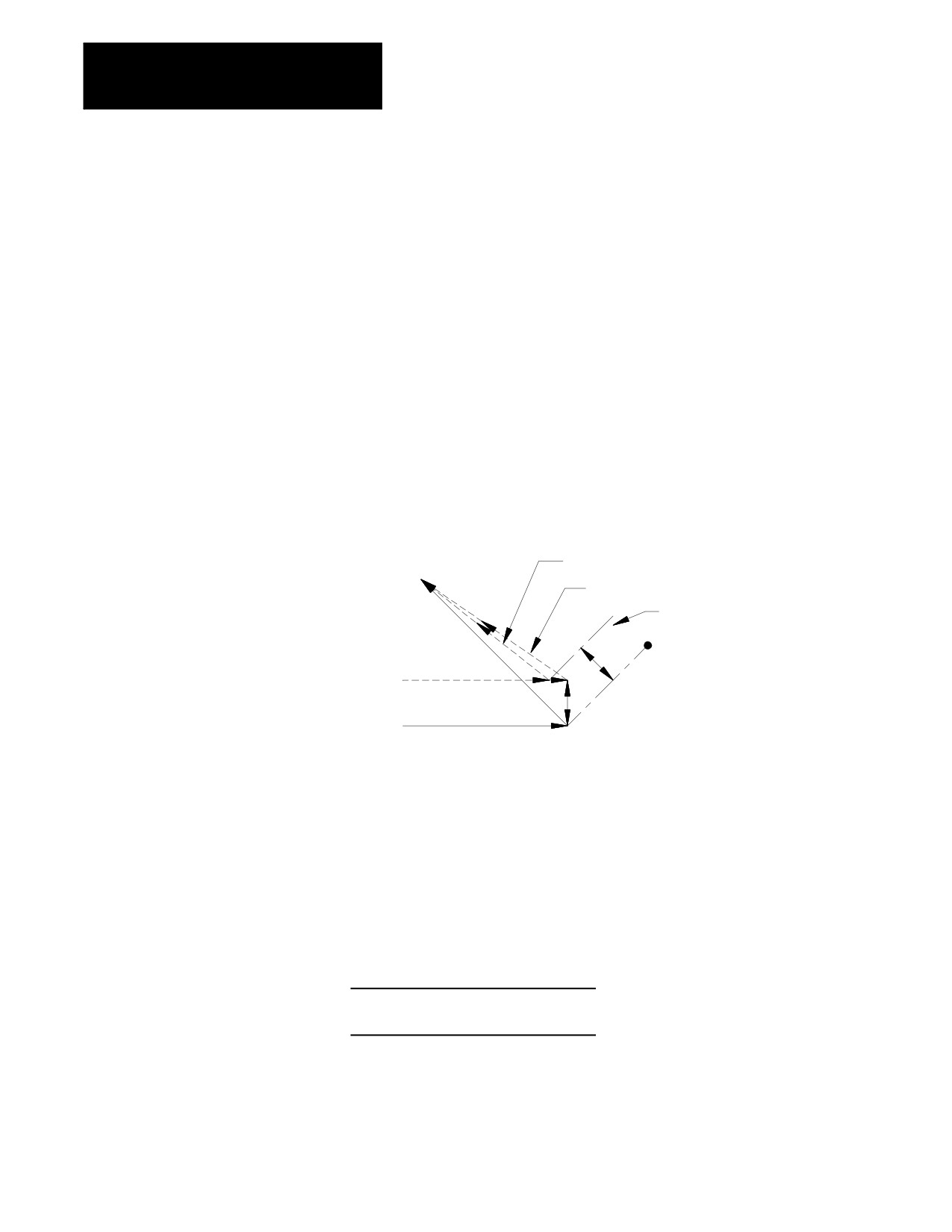
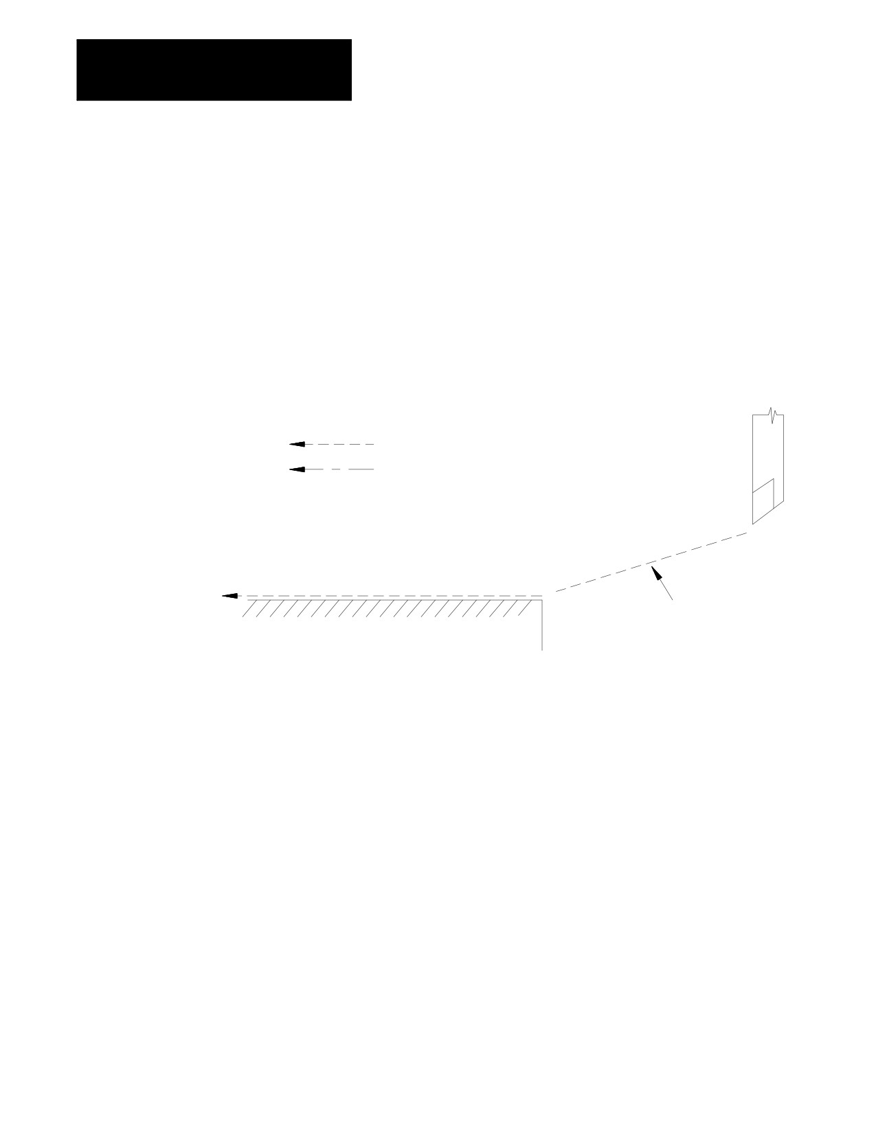
Figure 21.13
Exit Move Defined By An I, K Vector
Compensated path using I, K vector
Compensated path if no I, K in G40 block
Intercept line
I, K
r
Compensated path
Programmed path
r
Figure 21.13 is the exception. The change in length of the compensated
path is more than one radius of the tool. In this special case, this offset is
limited to one radius of the tool. The direction of the offset is towards the
point of intersection of the I K vector and the current compensated tool
path.
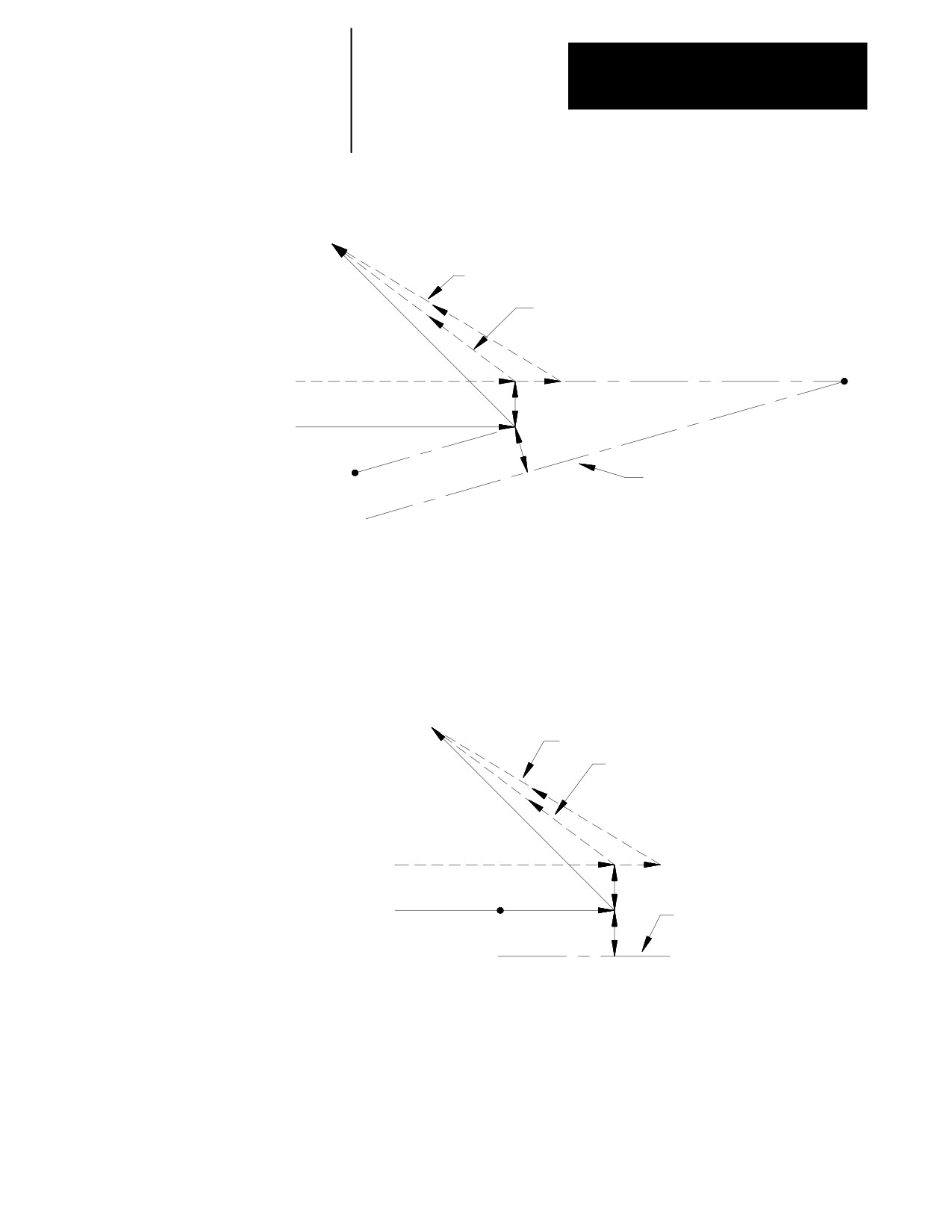
Example 21.6
Exit Move Defined By An I,K Vector But Limited To Tool Radius
Assume T1 radius is 3
N10 Z10.G41T1
N11 X10.Z2.I3K-10.G40;
21-18
Chapter 21
Tool Tip Radius Compensation (TTRC)
Function
Figure 21.14
Results of Example 21.6
Compensated path using I, K vector
Compensated path if no I, K in G40 block
N11
Compensated path
r
r
Programmed path
N10
r
I, K
Intercept line
If the vector defined by I and/or K is parallel to the programmed tool path,
the resulting exit move is offset in the opposite direction of the I and/or K
vector by one radius of the tool.
Figure 21.15
Exit Move When I, K Vector Is Parallel to Programmed Tool Path
Compensated path using I, K vector
Compensated path if no I, K in G40 block
Compensated path
r
r
Programmed path
Intercept line
I, K
r
Important: If one I and/or K value is programmed without the second one,
the value of the second I- and/or K-word defaults to 0.
21-19
Chapter 21
Tool Tip Radius Compensation (TTRC)
Function
21.4
We demonstrate the actual tool paths taken by the cutting tool when using
TTRC type B by pictorial representation. The following subsections
TTRC Tool Paths (Type B)
describe the cutter path along with a figure to clarify the description.
21.4.1
An entry move is defined as the path that the cutting tool takes when the
TTRC Type B Entry Moves
TTRC function first becomes activated in a program. Figure 21.16 gives
an example of a typical entry move.
Figure 21.16
TTRC Entry Move
Programmed tool path
Cutting tool center path
Cutting tool
G42 TTRC right
Compensation entry move
Workpiece
Important: Any entry move into TTRC must be a linear move. Initial
activation of TTRC by designation of either G41, G42, or T-word in a
circular cutting mode (G02 or G03) is not allowed. The G41 or G42
commands can be designated in a circular block to change TTRC direction,
or a new T-word can be designated to change cutter radius, as long as
TTRC is already active.
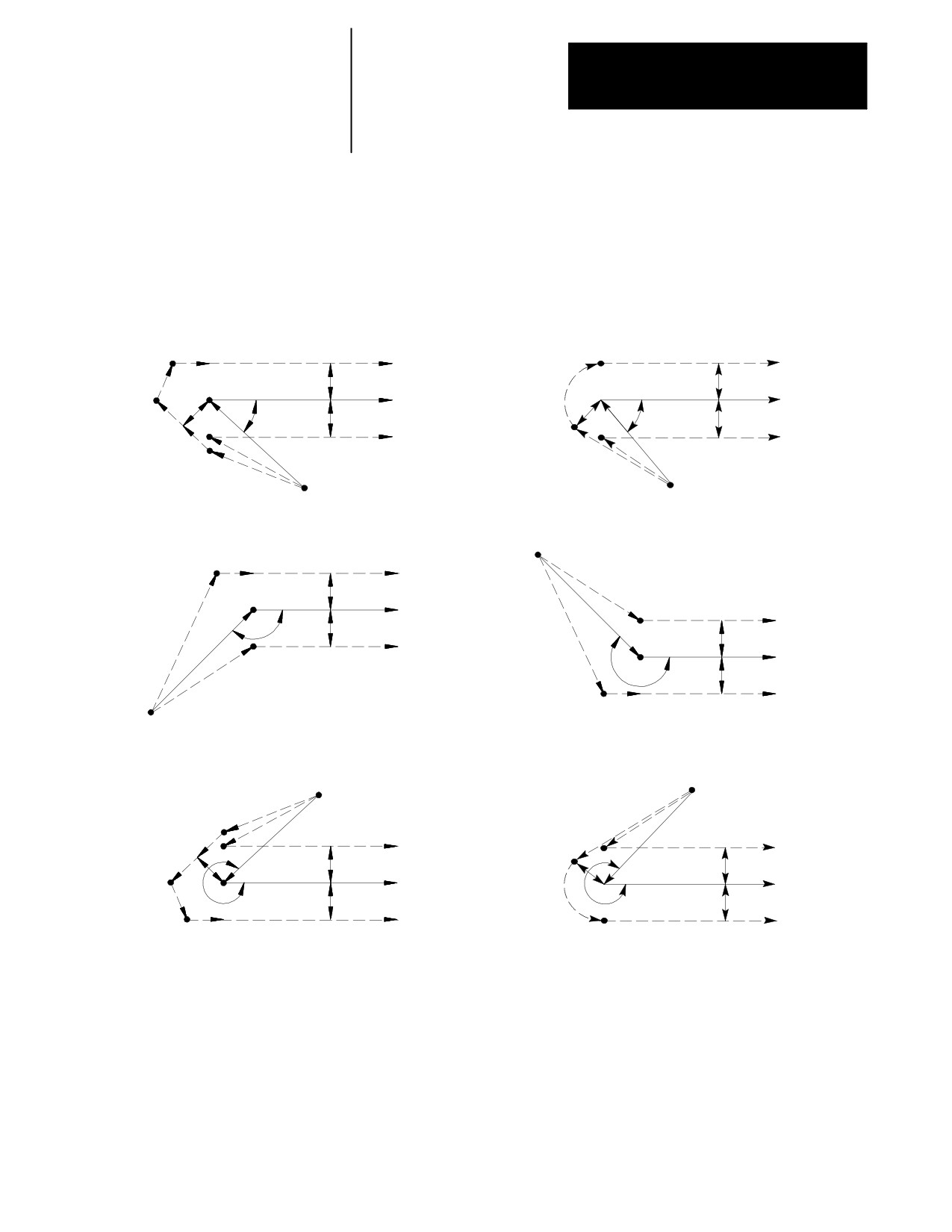
The entry move of the cutting tool for type B TTRC can generate extra
motion blocks to attempt to prevent gouging of the part as may sometimes
occur using compensation type A. Type B TTRC keeps the cutting tool at
least one radius away from the start-point of the next block at all times
during an entry move. The final end-point of the entry move is a position
at right angles to and on the left or right side of the next programmed move
in the currently defined plane.
21-20
Chapter 21
Tool Tip Radius Compensation (TTRC)
Function
Figure 21.17 and Figure 21.18 show examples of typical entry moves using
type B TTRC.
Figure 21.17
Tool Path for Entry Move Straight Line-to-Straight Line
G39 (Linear Generated Blocks)
G39.1 (Circular Generated Block)
0
£q £90
0
£q £90
E
C
D
D
r
G41
G41
r
r
C
Programmed
Programmed
r
r
q
path
q
path
r
r
r
G42
B
G42
r
B
Start-point
Start-point
A
A
180
£q £270
90
£q £180
A
Start-point
B
r
C
G41
r
Programmed
q
path
G41
r
r
G42
Programmed
q
path
r
G42
A
B
r
C
Start-point
G39 (Linear Generated Blocks)
G39.1 (Circular Generated Block)
270
£q £360
270
£q £360
A
A
Start-point
Start-point
B
r
G41
G41
B
r
r
r
r
C
Programmed
Programmed
r
q
path
q
path
r
r
G42
G42
r
E
D
C
D
21-21
Chapter 21
Tool Tip Radius Compensation (TTRC)
Function
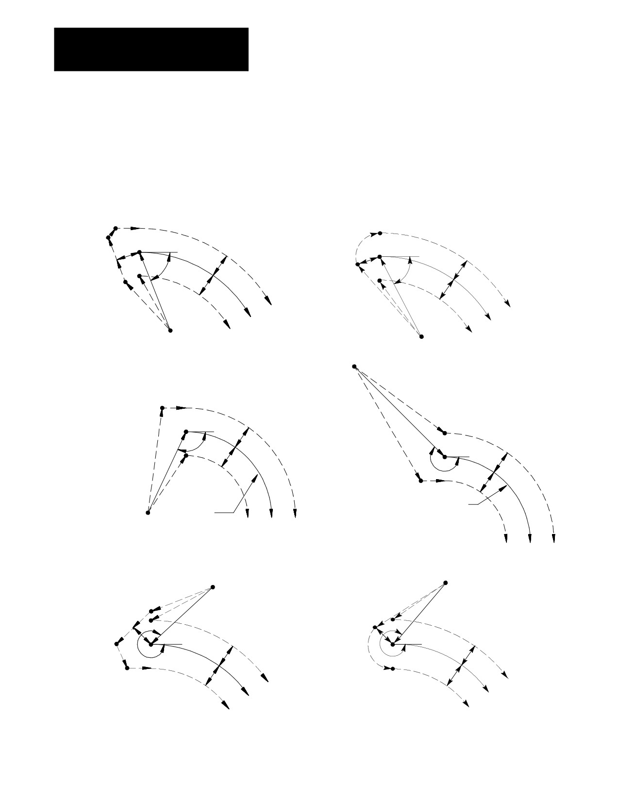
If the next programmed move is circular (an arc), position the tool at right
angles to a tangent line drawn from the start-point of that circular move.
Figure 21.18
Tool Path for Entry Move Straight Line-to-Arc
G39 (Linear Generated Blocks)
G39.1 (Circular Generated Block)
0
£q £90
0
£q £90
r
r
r
r
q
r
q
r
r
r
r
G41
G41
Programmed path
Programmed path
G42
Start-point
G42
Start-point
Start-point
90
£q £180
180
£q £270
r
r
q
r
r
q
r
r
Programmed
Programmed path
Path
Start-point
G42
G41
G42
G41
G39 (Linear Generated Blocks)
G39.1 (Circular Generated Block)
270
£q £360
270
£q £360
Start-point
Start-point
r
r
r
r
q
q
r
r
r
r
r
G41
G41
Programmed path
Programmed path
G42
G42
21-22

Chapter 21
Tool Tip Radius Compensation (TTRC)
Function
There is no limit to the number of blocks that can follow the programming
of G41 or G42 before an entry move takes place. The entry move is
always the same regardless of the number of blocks that do not program
motion in the current plane for compensation.
Example 21.7
Sample Entry Move After Non-Motion Blocks
Assume current compensation plane is the ZX plane.
N01X0Z0;
N2G41;
This block commands compensation left.
N3M02;
This is not the entry block since no axis
motion takes place in the current plane.
N4...;
No axis motion in current plane.
N5...;
No axis motion in current plane.
N6...;
No axis motion in current plane.
”
”
”
”
”
”
N999X1Z1;
This is the entry move for the previously
programmed G41.
Your system installer selects in AMP the allowable number of non-motion
blocks that are allowed during TTRC before the entry move must be
re-initialized. See section 22.5.2.
For example, assume that your system installer has designated that only
two non-motion blocks can be performed. Then, if more than two blocks
during TTRC do not contain axis motion in the current plane, the entry
move is re-performed at the next block containing axis motion in the
current plane.
Example 21.8
Too Many Non-Motion Blocks During TTRC
Assume current plane to be the ZX plane and the system installer has
designated that only two non-motion blocks can be performed before
TTRC is re-initialized.
N1X0Z0;
N2G41X1Z1;
Entry move TTRC left.
N3...;
No axis motion in current plane.
N4...;
No axis motion in current plane.
N5X4Z-4;
New entry move TTRC left.
21-23
Chapter 21
Tool Tip Radius Compensation (TTRC)
Function
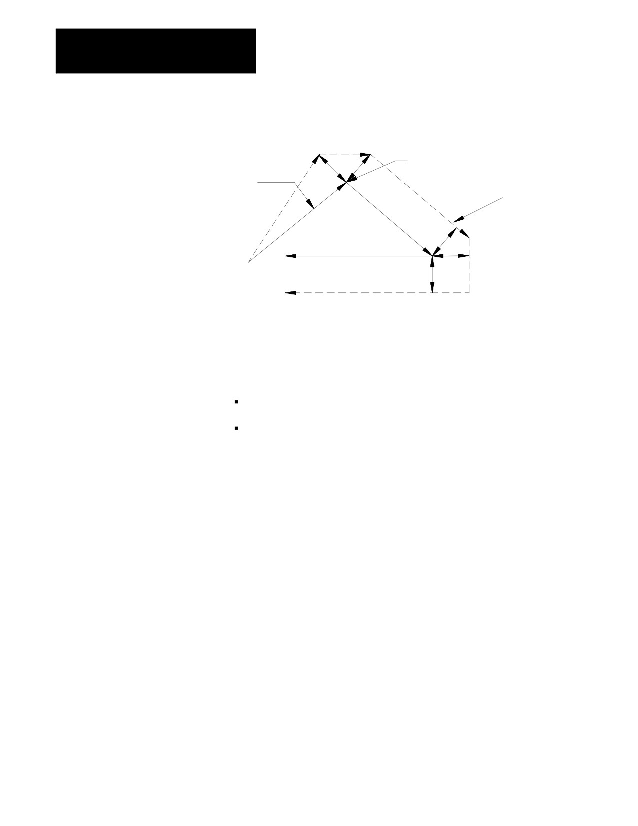
Figure 21.19
Too Many Non-Motion Blocks
Too many non motion
r
Programmed
r
blocks here
path
TTRC
reinitialized here
G41
r
r
r
21.4.2
Program a G40 to cancel the TTRC feature. Refer to the path that is taken
TTRC Type B Exit Moves
when the tool leaves TTRC is referred to as the exit move. The path that
the tool follows during an exit move is dependant on:
The direction of compensation (G41 or G42).
The angle between the last motion made in TTRC (in the current
compensation plane) and the motion of the of the exit move.
Designating a tool offset number T00 in a program does not cancel TTRC
and does not generate an exit move. TTRC simply continues on as if a tool
radius had been changed to a radius of zero. See page 21-30 for
information about changing cutter radius). The exit move (if T00 is the
active tool radius) is then equal to the programmed tool path.
Important: An exit move cannot be a circular move (G02 or G03). Any
exit move must be programmed on a linear path. Any attempt to generate
an exit move by using a circular path generates an error.
21-24
Chapter 21
Tool Tip Radius Compensation (TTRC)
Function
Example 21.9 gives some sample exit move program blocks.
Example 21.9
Sample Exit Move Segments
Assume the current plane to be the ZX plane.
N100X1Z1;
N110X3Z3G40;
Exit move.
N100X1Z1;
N110G40;
N120X3Z3;
Exit move.
N100X1Z1;
N110G40;
N120...;
No axis motion
in
the
current
plane.
N130...;
No axis motion
in
the
current
plane.
N140...;
No axis motion
in
the
current
plane.
”
”
”
”
N200X3Z3;
Exit move.
N100X1Z1;
N110...;
No axis motion
in
the
current
plane.
N120...;
No axis motion
in
the
current
plane.
N130...;
No axis motion
in
the
current
plane.
”
”
”
”
200G40X3Z3;
Exit move.
Provided the number of non-motion blocks in the compensation mode has
not exceeded a value selected by your system installer in AMP, all of the
program blocks in Example 21.9 produce the same exit move.
The exit of the cutting tool for type B TTRC takes the shortest possible
path to the end-point of the exit move for inside corners only. For outside
tool corners, the cutting tool always remains at least the radius of the
cutting tool away from the end-point of the last move in compensation.
You can redefine the start-point by using an I- and/or K-word as described
later in this section. The end-point of the exit move is no longer offset to
the left or right.
21-25
Chapter 21
Tool Tip Radius Compensation (TTRC)
Function
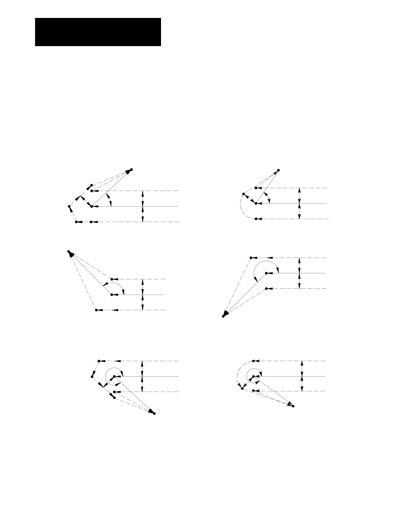
Figure 21.20 and Figure 21.21 show examples of typical exit moves using
type B TTRC. All examples assume that the number of non-motion blocks
before the designation of the G40 command has not exceeded the number
allowed as determined by your system installer in AMP.
Figure 21.20
Tool Path for Exit Move Straight Line-to-Straight Line
G39 (Linear Generated Blocks)
G39.1 (Circular Generated Block)
0
£q £90
0
£q £90
E
D
End-point
End-point
D
G42
r
G42
C
r
r
r
q
Programmed
r
q
Programmed
r
C
path
path
r
r
G41
G41
B
r
A
B
A
90
£q £180
180
£q £270
End-point
C
A
B
r
G42
r
q
Programmed
G42
path
r
r
q
G41
Programmed
path
r
G41
B
r
A
C
End-point
G39 (Linear Generated Blocks)
G39.1 (Circular Generated Block)
270
£q £360
270
£q £360
B
r
A
B
A
G42
G42
r
r
q
Programmed
q
Programmed
C
path
r
path
r
r
r
r
G41
G41
r
C
D
End-point
End-point
D
E
21-26