9/Series CNC Lathe. Operation and Programming Manual - page 15
Chapter 17
Spindles
17.6
Use this feature to synchronize the position and/or velocity between two
spindles with feedback using your 9/440, 9/260, or 9/290 control.
Synchronized Spindles
Two types of synchronization are available:
Velocity — synchronizes only the speed between two spindles
Velocity and Position — synchronizes the speed and angular
position between two spindles
Prior to activation, you are responsible for selecting the proper gear ranges
and ratios. The gear ratio between the feedback device and the spindle
must be 1:1. Any other type, including nonunit ratios, will not allow
repeatability of the orientation of your spindle and may cause positioning
offset inaccuracies.
Spindle Configuration
Your system installer selects two spindles to make up the synchronization
pair, which consists of the controlling and follower spindles. During
synchronization, the controlling spindle initiates spindle motion while the
follower spindle attempts to synchronize with it. Your system installer
determines the configuration of these spindles. Refer to your system
installer’s documentation for more information about spindle
configuration.
Gear ranges are set separately for each spindle. If the controlling spindle
speed is outside of the current follower spindle gear range when a seek is
attempted, the controlling spindle will ramp to within the follower’s limits
set in AMP.
Selecting the Controlling Spindle
The synchronized spindle’s controlling spindle, which is determined by
your system installer, must be programmed as the part program’s
controlling spindle in your part program prior to synchronization. Use one
of the G12 codes (G12.1, G12.2, and G12.3) to designate the active
controlling spindle for spindle synchronization. Refer to page 17-9 for
more information about the G12 codes and your system installer’s
documentation to identify your controlling spindle.
Important: Typically, the programmed speed of the controlling spindle
dictates the speed of the follower spindle. For more information about
valid gear ranges, refer to page 17-28.
17-23
Chapter 17
Spindles
17.6.1
Use these three G--codes to manipulate the spindle synchronization feature:
Using the Spindle
Set spindle positional synchronization (G46)— sets the follower spindle
Synchronization Feature
speed/direction and relative position offset to match the controlling
spindle.
Set active spindle speed synchronization (G46.1)— sets the follower
spindle speed/direction to match the controlling spindle.
Deactive spindle synchronization (G45)— shuts off synchronization
while maintaining the controlling and follower spindles’current speed
and direction.
Activate Spindle Positional Synchronization (G46)
Use the “Activate Spindle Positional Synchronization” to synchronize
speed and position. The position is based on a programmed S--word
(degrees). If you do not program an S--word in the G46 block, it will
automatically go to the relative positional offset, set by your system
installer. Refer to your system installer’s documentation for more
information.
During a G46, the spindles attempt to match speeds. Once the speeds are
matched, the spindles attempt to synchronize their relative positional
offset. Once synchronization is achieved, the active spindle speed and
mode (M03, M04, M05, or M19) programmed for the follower spindle is
replaced by the current controlling spindle speed and mode.
Important: Changes in spindle speeds that would normally occur as a
result of CSS or other programmed changes to spindle speeds, directions,
and spindle speed override will not occur until synchronization is achieved.
The format for the G46 block is as follows:
G46S__;
Where:
Defines:
S
the angular offset between two spindles (degrees)*
*The range for the S--word is 0 to 360. Your system installer defines where 0_ is for each
spindle. The value defined as the offset value is absolute and independent of spindle direction.
Important: No other program letters are allowed in the G46 block except
auxiliary letters and system installer M--codes.
17-24
Chapter 17
Spindles
The following example assumes that the controlling and follower spindles
were defined as spindle 2 and spindle 1, respectively, by your system
installer.
Example 17.4
Spindle Synchronization
M03 S200;
Spindle 1 clockwise 200 rpm
M04.2 S400;
Spindle 2 counterclockwise at 400 rpm
G12.2;
Spindle 2 as controlling spindle
G46 S90;
Spindle 1 changes direction and accelerates to spindle
2’s speed; spindle 1 synchronizes angular position with
spindle 2 (offset 90 degrees)
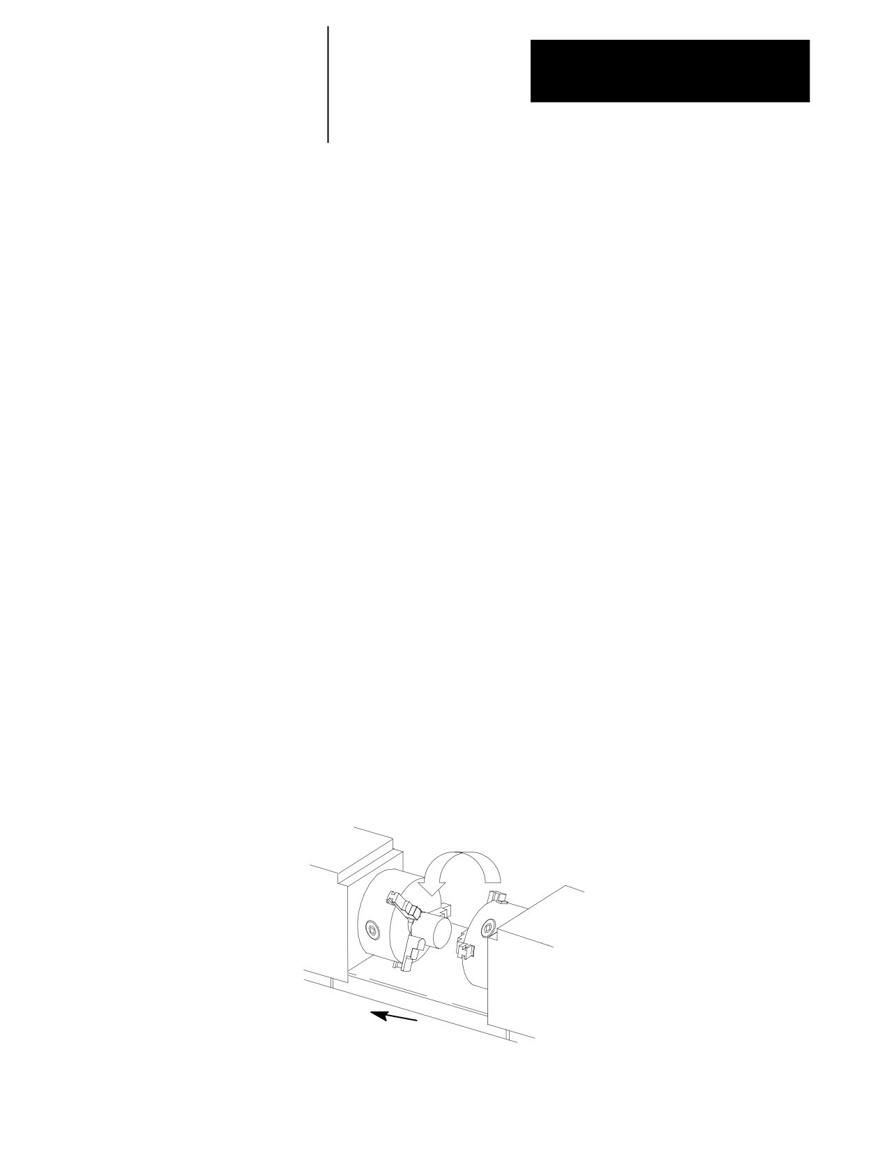
Example 17.5 shows two spindles attempting synchronization to
transferring a part. The following steps describe the synchronization
process in this example.
1.
The follower spindle, B, attempts to match its velocity with the
controlling spindle (A).
2.
Once velocities are matched, spindle B reaches its relative position,
which is offset from the position of spindle A.
3.
When synchronization is achieved, the spindle axis advances to
engage the part.
4.
Spindle B clamps the part held by spindle A.
5.
Spindle A unclamps, transferring the part to spindle B.
6.
The spindles move apart and synchronization is disabled (G45).
Example 17.5
A
B
Spindle B moves into spindle A.
17-25
Chapter 17
Spindles
Activate Spindle Speed Synchronization (G46.1)
Use the “Activate Spindle Speed Synchronization” to synchronize speed
and direction only. Using G46.1 does not guarantee a consistent positional
offset between the two spindles. During a G46.1, the follower spindle
attempts to synchronize speeds with the controlling spindle. Once
synchronization is achieved, the current spindle speed and mode (M03,
M04, M05, or M19) programmed for the follower spindle is replaced by
the current controlling spindle speed and mode programmed. The original
follower spindle speed and direction is not retained.
Important: Changes that occur as a result of CSS or other programmed
changes to spindle speeds, directions, and spindle speed override will not
occur until synchronization is achieved.
The format for the G46.1 cycle is as follows:
G46.1;
Important: No other program letters are allowed in the G46.1 block
except auxiliary letters and system installer M--codes.
Deactivate Spindle Synchronization (G45)
Use G45 to deactivate the synchronized spindle feature. When
synchronization is deactivated, the follower spindle will remain in the
same state (M03, M04, M05, or M19) and at the last programmed speed
for controlling spindle until you change the program settings or if your
system installer writes PAL to recommand the spindle.
In a multiprocess system, if the spindles are synchronized, and an
end--of--program (M02) is reached on the process synchronizing the
spindles, both spindles will obey the end--of--program commands. Then
synchronization will be disabled.
The format for the G45 cycle is as follows:
G45;
Important: No other program letters are allowed in the G45 block except
auxiliary letters and system installer M--codes.
17-26
Chapter 17
Spindles
17.7
When using the synchronized spindle feature, remember:
Special Considerations for
you cannot retrace through a synchronization block (G45, G46, or
Spindle Synchronization
G46.1). However, you can retrace through blocks where
synchronization was already active.
in dual--process systems, both spindles used for synchronization
must be configured in the process that is programming spindle
synchronization. Shared spindles are acceptable if they area
already controlled by the process requesting synchronization.
gear changes are not allowed during synchronization. If spindle
speeds exceed the gear range of either spindle, the spindles will be
limited to the more restrictive spindle’s values.
due to the servo switch from open-- to closed--loop during
synchronization, a one--iteration hesitation in the spindles may be
seen when this switch occurs. This small deceleration may be
more apparent in systems with a smaller spindle motor or if
synchronization is done at higher speeds.
Program Restart, Mid--Start, and Interrupt Macros will be allowed.
If synchronization is disabled during an interrupt macro, it will
resynchronize upon return, in the event that all of the condition
checks listed in this section allow it to, otherwise a decode error
will result. Mid--Start and restart must also pass all conditions
described in this section.
you are responsible for selecting proper gear ranges prior to
activating synchronization.
The following features cannot be used while synchronization is active:
solid--tapping
Virtual C programming
The following features cannot be used while synchronization is ramping:
deep--hole peck drilling
threading
Important: Virtual C and threading are available on synchronized spindles
once synchronization is achieved.
17-27
Chapter 17
Spindles
When synchronization is active, any part program commands
destined for the follower spindle (i.e., M03, M03.2,
M03.3...G12.1, G12.2, and G12.3) will cause an error. On a
multiprocess configuration, this is true of either process.
On a multiprocess 9/Series, the process controlling the controlling
spindle also controls the follower spindle when spindle
synchronization is active. If it is unable to obtain control, an error
results: UNABLE TO SYNCH IN CURRENT MODE.
Important: Typically, the programmed speed of the controlling spindle
dictates the speed of the follower spindle. In the event that the
programmed speed exceeds the maximum or drops below the minimum
allowable values for the synchronized pair, the spindle speed will be
restricted to those allowable values, as shown on page 17-28.
the example below shows what will happen when:
no overlap occurs between the controlling and follower
spindles’gear ranges
the controlling spindle has a higher gear range than the
follower spindle
the controlling spindle has a lower gear range than the
follower spindle
Example 17.6
Valid Gear Ranges for Synchronized Spindles
Controlling Spindle
Follower Spindle
Requested
Valid Programmed
Spindles will
Gear Range
Gear Range
Spindle Speed
Spindle Speeds
Synchronize at
(RPM)
(RPM)
(RPM)
(RPM)
(RPM):
1000 to 3000
100 to 300
1500
None
N/A
1000 to 3000
800 to 1500
1800
1000 to 1500
1500
1000 to 3000
1800 to 3200
1500
1800 to 3000
1800
in a multiprocess system, if the spindles are synchronized, and an
end--of--program is reached on the process synchronizing the
spindles, both spindles will obey the end--of--program commands
and synchronization is disabled.
END OF CHAPTER
17-28
Chapter
18
Programming Feedrates
18.0
This chapter describes 9/Series control feedrates, including special AMP
assigned feedrates and automatic acceleration/deceleration.
Chapter Overview
For information about:
See page:
Feedrates
18-1
Special AMP-assigned Feedrates
18-8
Automatic Acceleration/Deceleration
18-10
18.1
Feedrates are programmed by an F-word followed by a numeric value.
You can enter feedrates in a part program block or through MDI. They
Feedrates
become effective in the block in which they are programmed and apply to
all G01, G02 and G03 axis motion. If the block requires rapid traverse
motion (G00), the programmed feedrate is ignored for that block, but is
stored in control memory as the active feedrate.
Feedrates are modal. They remain active in control memory unless
replaced with a different feedrate programmed with an F-word.
Feedrate modes are either G95 (cutting tool distance per workpiece
revolution) or G94 (cutting tool distance per minute). Table 18.A shows
the possible feedrate units depending on axis type.
Table 18.A
Feedrate Units
Active G-code
Linear Axis Feed
Rotary Axis Feed
G71 and G94
millimeters/min.
degrees/min.
G71 and G95
millimeters/rev.
degrees/rev.
G70 and G94
inches/min.
degrees/min.
G70 and G95
inches/rev.
degrees/rev.
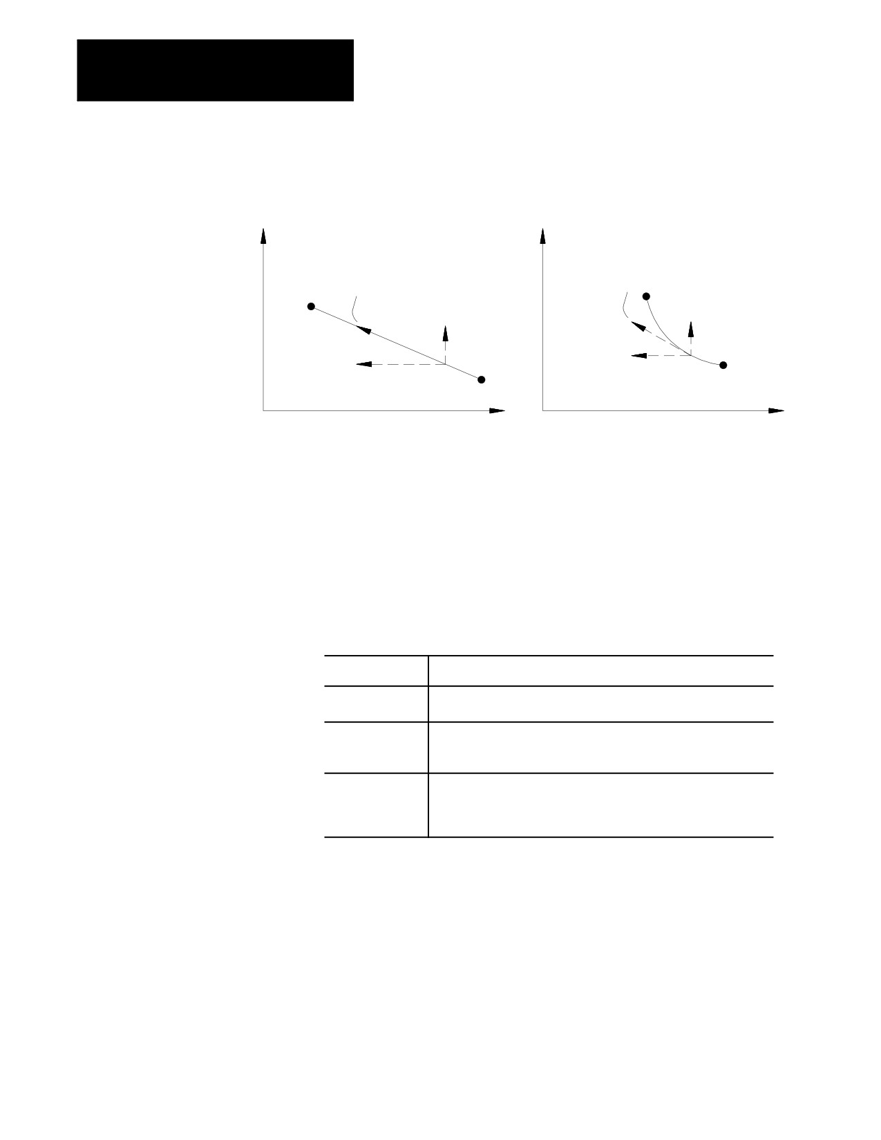
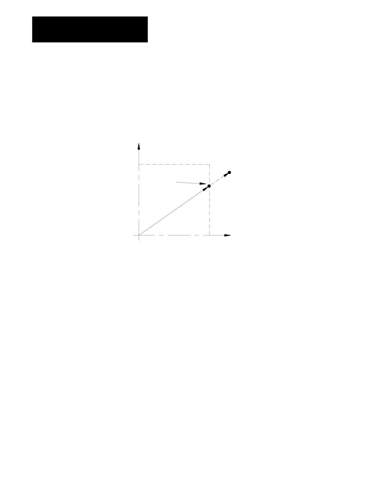
Feedrates for linear and circular interpolation are “vector” feedrates. All
axes move simultaneously at independent feedrates so that the rate along
the effective path is equal to the programmed feedrate. See Figure 18.1.
18-1
Chapter 18
Programming Feedrates
Figure 18.1
Programming a Tangential Feedrate
X
X
Linear interpolation
Circular interpolation
programmed
programmed
end
feedrate
feedrate
end point
point
X axis
feedrate
X axis
feedrate
start
point
Z axis
Z axis
start
feedrate
feedrate
point
Z
Z
For example, if a feedrate is programmed as F100.0 millimeters per
minute, and a linear move is made from X0, Z0 to X10, Z10, the feedrate
along that 45 degree angular path would be 100.0 mmpm. The actual
feedrate of each axis is approximately 70.7 millimeters per minute.
18.1.1
When the cutting tool is offset from a programmed path (as in the case of
TTRC), the programmed feedrate is applied to the center of the tool radius
Feedrates Applied During
for all linear and outside arc paths.
TTRC
For these paths:
The result:
linear
is not significant because the speed of the tool tip relative to the part
surface remains the same as the programmed feedrate.
outside arc
speed of the tool tip relative to the part surface is less than the
programmed feedrate. This generally causes no problem and so the
control does not take corrective action.
inside arc
speed of the tool tip relative to the part surface would be greater than
the programmed feedrate. Since this could cause excessive tool
loading and poor cutting performance, the 9/Series control
automatically takes corrective action.
18-2
Chapter 18
Programming Feedrates
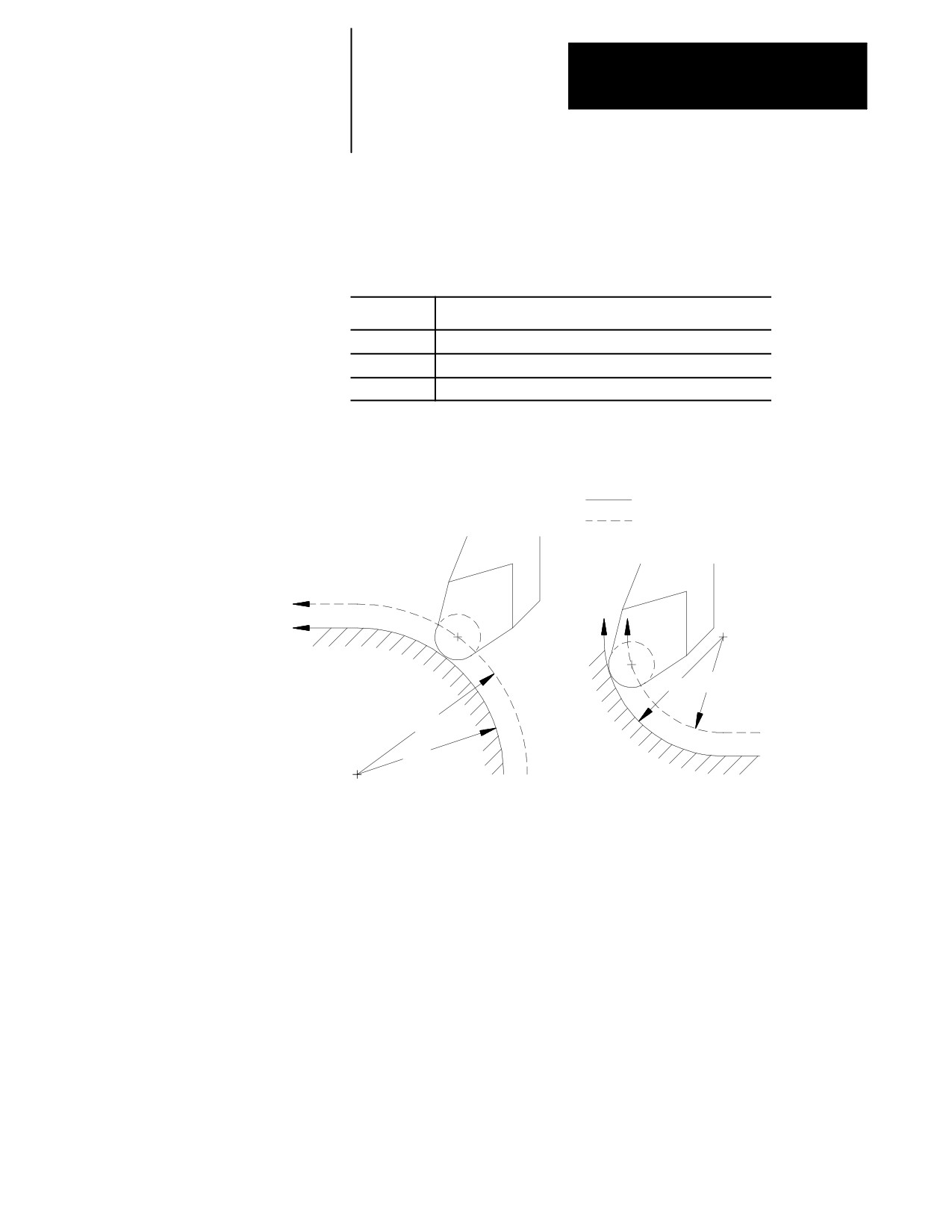
For outside arc paths, the speed of the tool tip relative to the part surface
can be determined using the following formula:
Rp
Tool tip speed
= F x
----
Rc
Where :
Is :
F
programmed feedrate
Rc
radius of the arc measured to the center of the tool radius
Rp
programmed radius of the arc
Figure 18.2
Inside and Outside Arc Feedrates with TTRC
programmed tool path
tool radius center path
Cutting
outside arc
Cutting
inside arc
Rc < Rp
F is reduced
Rc > Rp
Rp Rc
F as programmed
Rc
Rp
For inside arc paths, the control automatically maintains the programmed
feedrate at the tool tip. The actual tool radius center feedrate reduces as
needed through the arc path, and then it returns to the programmed feedrate
after the arc is completed.
During inside arc paths, the control decreases the tool radius center
feedrate by the ratio of Rc/Rp. If the Rc value is very small compared to
Rp, as in the case of a small arc being cut with a large diameter tool, the
value of Rc/Rp is nearly zero, and the tool radius center feedrate becomes
excessively small.
To avoid this problem, your system installer must set a minimum feed
reduction percentage (MFR) in AMP. This sets a minimum feedrate to be
used whenever the value of Rc/Rp is very small. If Rc/Rp < MFR, the
control reduces the tool radius center feedrate no more than the MFR
percentage.
18-3
Chapter 18
Programming Feedrates
18.1.2
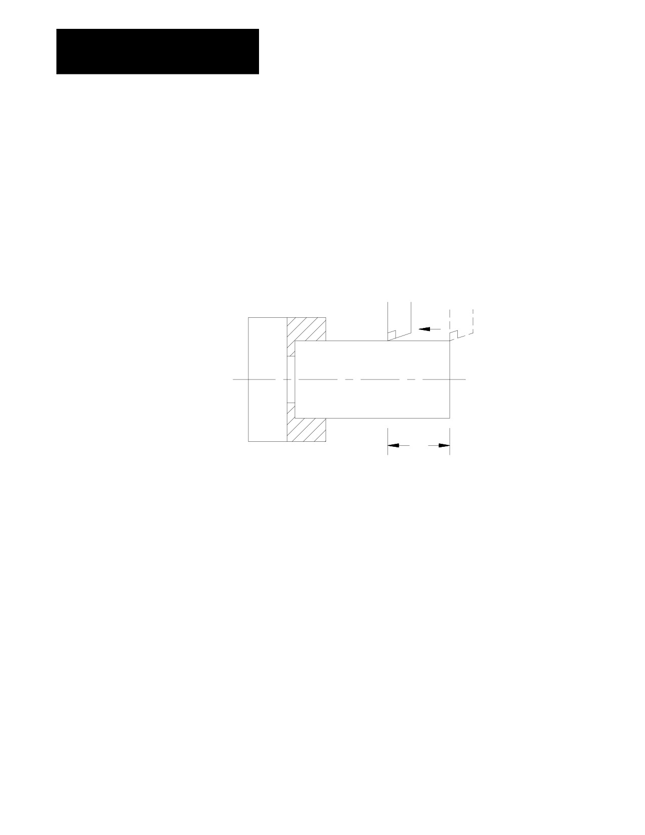
In the G94 mode (feed per minute), the numeric value following address F
represents the distance the axis or axes move (in inches or millimeters) per
Feed Per Minute Mode (G94)
minute. If the axis is a rotary axis, the F-word value represents the number
of degrees the axis rotates per minute.
To program a feedrate of 55 mm of tool motion per minute program:
G94 F55.;
Figure 18.3
Feed Per Minute Mode (G94)
Cutting tool
Chuck
Workpiece
“F” is the distance
the tool moves per minute.
F
When changing from G95 to G94 modes, you must program a feedrate in
the first G94 block.
Since the G94 code is modal, any F-word designated in any block after the
G94 is considered a feed distance per minute until a G95 is executed.
Important: The controlling spindle determines which spindle per
revolution value to use when calculating the feed per revolution.
18.1.3
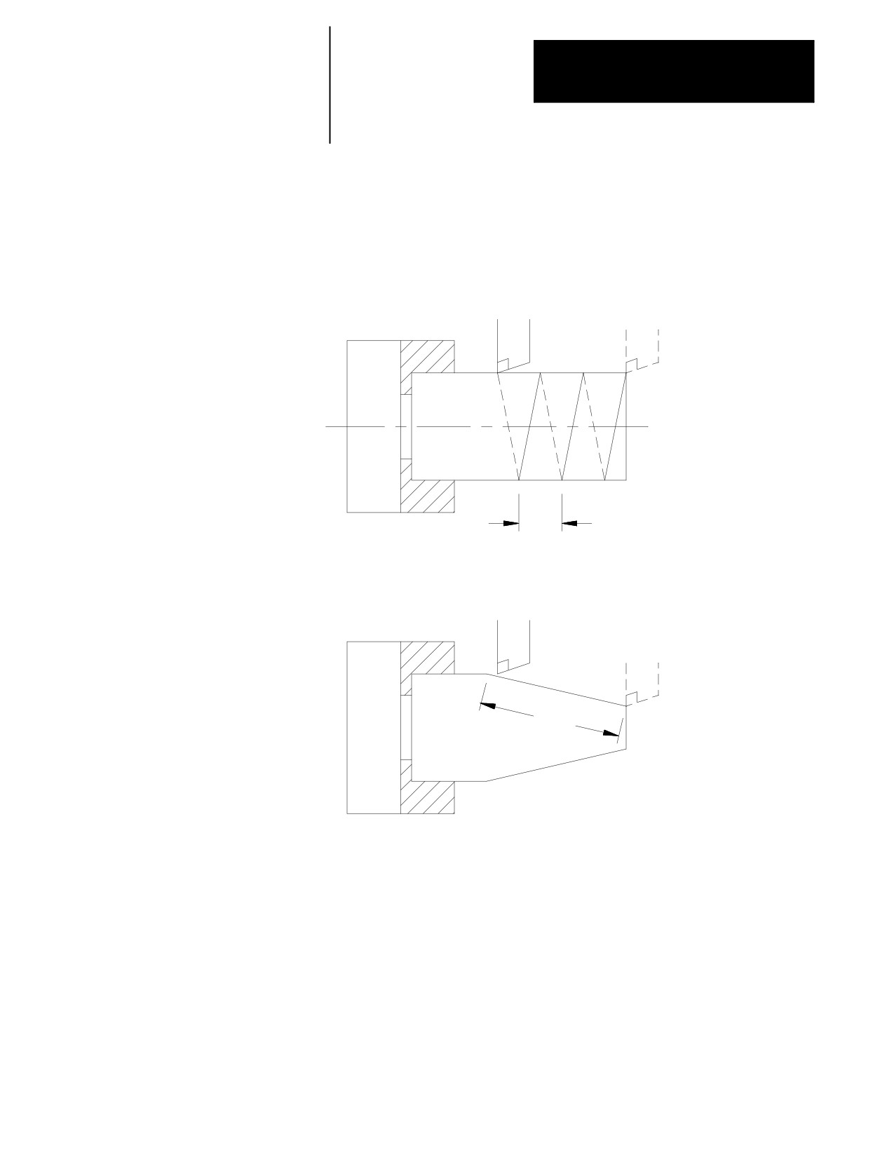
In the G95 mode (feed per revolution), the numeric value following
Feed Per Revolution Mode
address F represents the distance the axis or axes move (in inches or
millimeters) per revolution of the spindle. If the axis is a rotary axis, the
(G95)
F-word value represents the number of degrees the axis rotates per
revolution of the spindle.
To program a feedrate of 1.5 mm per revolution of workpiece program:
G95 F1.5;
When changing from G94 to G95 modes, you must program a feedrate in
the first G95 block.
18-4
Chapter 18
Programming Feedrates
Since the G95 code is modal any F-word designated in any block after the
G95 is considered a feed distance per spindle revolution until a G94 is
executed.
Figure 18.4
Feed Per Revolution Mode (G95)
Cutting tool
Chuck
Workpiece
“F”is the distance the tool moves per
F
revolution of the workpiece.
Cutting tool
B
Chuck
A
20.0
Workpiece
If G95 F.2 is the feedrate, the tool moves from
A to B in 100 revolutions of the workpiece.
18-5
Chapter 18
Programming Feedrates
18.1.4
Rapid feedrate drives all active axes at a speed which creates a linear
move. The control determines which axis must travel the furthest and
Rapid Feedrate
drives that axis at its maximum feedrate assigned in AMP. Use rapid
feedrate to position the tool to a specified point at a high speed. It is called
during the execution of a G00 code followed by an axis motion command
and in many of the canned cycles for positioning.
After the execution of a rapid move the control restores the previously
commanded feedrate.
You can drive axes at their maximum allowable speeds during the jogging
operations by holding down the <TRVRS> button while executing a jog
move. (For details on jogging an axis see chapter 4).
Use rapid feedrate to position axes to a specified point at a high speed. It
is called by executing a G00 followed by an axis motion command. It also
is called automatically for some of the motions made by the fixed cycles.
See the fixed cycle specifications.
When you command more than one axis to move at rapid feedrate, they are
driven together to produce a linear move. The control drives one of the
axes at its rapid feedrate and reduces the feedrate of the others as required
to make certain that all axes start and stop at the same time.
18.1.5
<FEEDRATE OVERRIDE> Switch
Feedrate Overrides
You can override feedrates programmed in any of the feedrate modes
(G93/94/95) using the <FEEDRATE OVERRIDE> switch on the MTB panel.
The <FEEDRATE OVERRIDE> switch has a range of 0-150% of the
programmed feedrate, and it can alter the programmed feedrate in 10
percent increments.
The control checks whether the feedrate resulting from the
<FEEDRATE OVERRIDE> switch setting exceeds the maximum cutting
feedrate set in AMP. If it does, the feedrate is restricted to the AMP
maximum.
An M49 (overrides disabled) causes the override amounts that are set by
the switches on the MTB panel to be ignored by the control. With M49
active, the override switches for feedrate, rapid feedrate, and spindle speed
are all set to 100%. They can be enabled by programming an M48
(overrides enabled). See chapter 10 for details.
The feedrate override switch overrides the current axis feedrate. This may
or may not be the currently programmed feedrate. In cases where Acc/Dec
or the feedrate clamp features have overridden the programmed feedrate,
the feedrate override switch adjusts the new Acc/Dec or clamped feedrate.
18-6
Chapter 18
Programming Feedrates
<RAPID FEEDRATE OVERRIDE>
Use <RAPID FEEDRATE OVERRIDE> on the MTB panel to override the
rapid feedrate for G00 mode in four increments:
F1 ---- percent value set in AMP by your system installer
25%
50%
100%.
Important: Normally this override is not active for any dry run motions
(see chapter 7) unless otherwise specified in PAL by your system installer.
Important: This override is also effective for jog moves that use the rapid
feedrate (see jogging using the <TRVRS> button in chapter 4).
Feedrate override switches disable
An M49 forces the override amounts that are set with the MTB panel to be
ignored by the control. With M49 active, the overrides for feedrate, rapid
feedrate, and spindle speed are all set to 100 percent. You can enable them
by programming an M48 (overrides enabled). See chapter 10 for details.
Feedhold
Your system installer can write PAL to allow the activation of a feedhold
state through the use of a button or switch. When activated, the control
decelerates and holds the current feedrate for all axes to zero until the
feedhold state is deactivated. For details on using feedhold, refer to
documentation provided by your system installer.
18-7
Chapter 18
Programming Feedrates
18.1.6
The maximum allowable speed for each axis is set in AMP. If any axis
feedrate exceeds the maximum allowable speed for that axis the control
Feedrate Limits (Clamp)
automatically adjusts the feedrate to a value that does not cause axis speed
to exceed its set limit.
Figure 18.5
Feedrate Clamp
X
FXMAX
Fp
F
FXMAX : maximum X axis feedrate
FZMAX : maximum Z axis feedrate
Fp
: programmed feedrate
F
: actual feedrate
Z
FZMAX
In Figure 18.5, when the commanded feedrate is Fp it causes the Z-axis
feedrate to exceed the maximum feedrate (FzMAX). The control then
adjusts the feedrate for both axes so that F becomes the actual feedrate.
When the feedrate is “clamped” to a value below the programmed feedrate
the control displays a flashing C next to the current axes feedrate. The
displayed axis feedrate is the actual feedrate of the tool, not necessarily the
programmed feedrate.
18.2
You can select special feedrates that are assigned in AMP. This section
covers the feedrates assigned in AMP for the single-digit F-word and the
Special AMP-assigned
external feedrate switch.
Feedrates
18.2.1
Program a one-digit numeric value (1-9) following the F-code to select
various pre-set feedrates. The digits 1-9 have corresponding numeric
Single-digit F-words
values for feedrates set in the F1 - F9 table described in chapter 2.
18-8
Chapter 18
Programming Feedrates
Important: Single-digit feedrates are always entered as per minute
feedrates (IPM or MMPM) regardless of the control’s current feedrate
mode. When a single-digit feedrate is programmed, the control
automatically switches to the IPM or MMPM mode. The control
automatically switches back to the previously active feedrate mode when
the next feedrate is programmed that is not a single-digit feedrate.
If there are no feedrates set in the tables that correspond to F1-F9. The
control treats F1-F9 as commanded feedrates.
Single-digit F-word feedrates are affected by the setting of the
<FEEDRATE OVERRIDE> switch as regular feedrates. Blocks that are
programmed to move at the rapid feedrate are still executed in the rapid
mode.
Important: A programmed F0 corresponds to the maximum cutting
feedrate (not normally the rapid feedrate) set in AMP by your system
installer. F0 generates an error if the feature is not used.
When you call a single-digit F-word, the F-word must be programmed
with no decimal point and a single digit. For example, F1 calls an assigned
feedrate correlating to the value set as feedrate 1. Designating F1. in a
program assigns a feedrate of 1 in the current feedrate mode.
18.2.2
Your system installer can install an optional external deceleration switch.
External Deceleration
Typically this is a mechanical switch mounted on the machine axes inside
the hardware overtravel switches. Refer to documentation prepared by
Feedrate Switch
your system installer for details on the application and location of this
switch.
When you activate this feature, any axis moves that are to take place at a
cutting feedrate (G01, G02, G03, etc.) use a special feedrate assigned in
AMP. Any axis moves that are to take place at a rapid feedrate (G00, etc.)
also uses a special feedrate assigned in AMP. These feedrates are
independent of each other and typically have different values. These
feedrate changes take place immediately when the feature becomes active,
even if this is in the middle of block execution.
Important: The feedrate set for the external deceleration feature for
cutting moves cannot exceed the maximum cutting feedrate.
18-9
Chapter 18
Programming Feedrates
If you use this feature simultaneously with the Dry Run feature, the
feedrates that are assigned to the External deceleration feature are used.
The feedrates for this feature are not related to the Dry Run feedrates,
although the operation of this feature is similar to Dry Run.
This feedrate is unaffected by the <FEEDRATE OVERRIDE> switch and the
<RAPID FEEDRATE OVERRIDE> settings, and it operates as if the switches
are set at 100 percent. Blocks that are programmed to move at the rapid
feedrate are still executed in the rapid mode.
Use this feature to protect the machine from harsh or sudden stops. If a
very high feedrate is active at the time that a hardware overtravel occurs,
damage to the machine can result or the machine can coast past a safe
range for axis motion. If the switch is installed before the overtravel area,
the feedrate of the move is reduced and the amount of coast into the
overtravel area is much less.
If the current feedrate is less than the feedrate set for the external
deceleration feature, it is accelerated to the external deceleration feedrate.
This can cause problems with part finish or can damage the tool if this
feedrate is higher than that which the part should be cut.
WARNING: Your system installer can write PAL to allow the
operator to select the external deceleration feedrate at any time.
This means that during normal automatic operation, you can
select external deceleration and replace all feedrates in the
program with the external deceleration feedrates. This can
result in damage to the machine, part, or injury to the operator.
18.3
There are two types of axis acceleration/deceleration available. They are:
Automatic
Exponential Acc/Dec
Acceleration/Deceleration
Uniform or Linear Acc/Dec
S--Curve Acc/Dec
These are used to produce smooth starting and stopping of the machines
axes and prevent damage to the machine resulting from harsh movements.
Your system installer determines the acc/dec parameter type (exponential
or linear) for some manual motion types. To determine which motion
types are configurable, refer to the following table. Refer to your system
installer’s documentation for more information about how your system is
configured.
18-10

Chapter 18
Programming Feedrates
Refer to the table below to determine the type of acceleration/deceleration
performed for manual motion and programmed moves.
Table 18.B
Acc/Dec Type Performed with Manual Motion and Programmed Moves
Motion Type
Always Uses Exponential
Configurable in AMP by
Always Uses Linear
Linear or S- Curve
Acc/Dec
System Installer via
Acc/Dec
Acc/Dec per G- code
Manual Acc/Dec Mode
Hand--pulse generator
n
Arbitrary angle moves (i.e.,
hand--pulse generator and
continuous and incremental
motion)
Homing
n
All programmed moves except
n
for G00 and exact stop
Manual continuous motion
n
Manual incremental motion
n
PAL axis mover
n
All moves programmed in G00
n
(positioning) mode
18-11
Chapter 18
Programming Feedrates
18.3.1
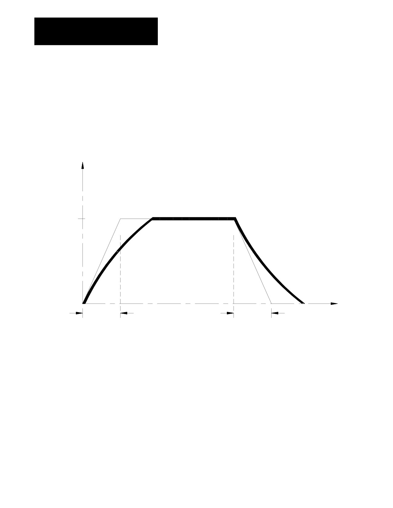
To begin and complete a smooth axis motion, the 9/Series control uses an
exponential function curve to automatically accelerate/decelerate an axis.
Exponential Acc/Dec
Your system installer sets the acceleration/deceleration time constant “T”
for each axis in AMP. Figure 18.6 shows axis motion using exponential
Acc/Dec.
Figure 18.6
Exponential Acceleration/Deceleration
Velocity
“F”is the programmed feedrate
“T”is the acceleration/deceleration
time constant
F
Time
T
T
18-12
Chapter 18
Programming Feedrates
18.3.2
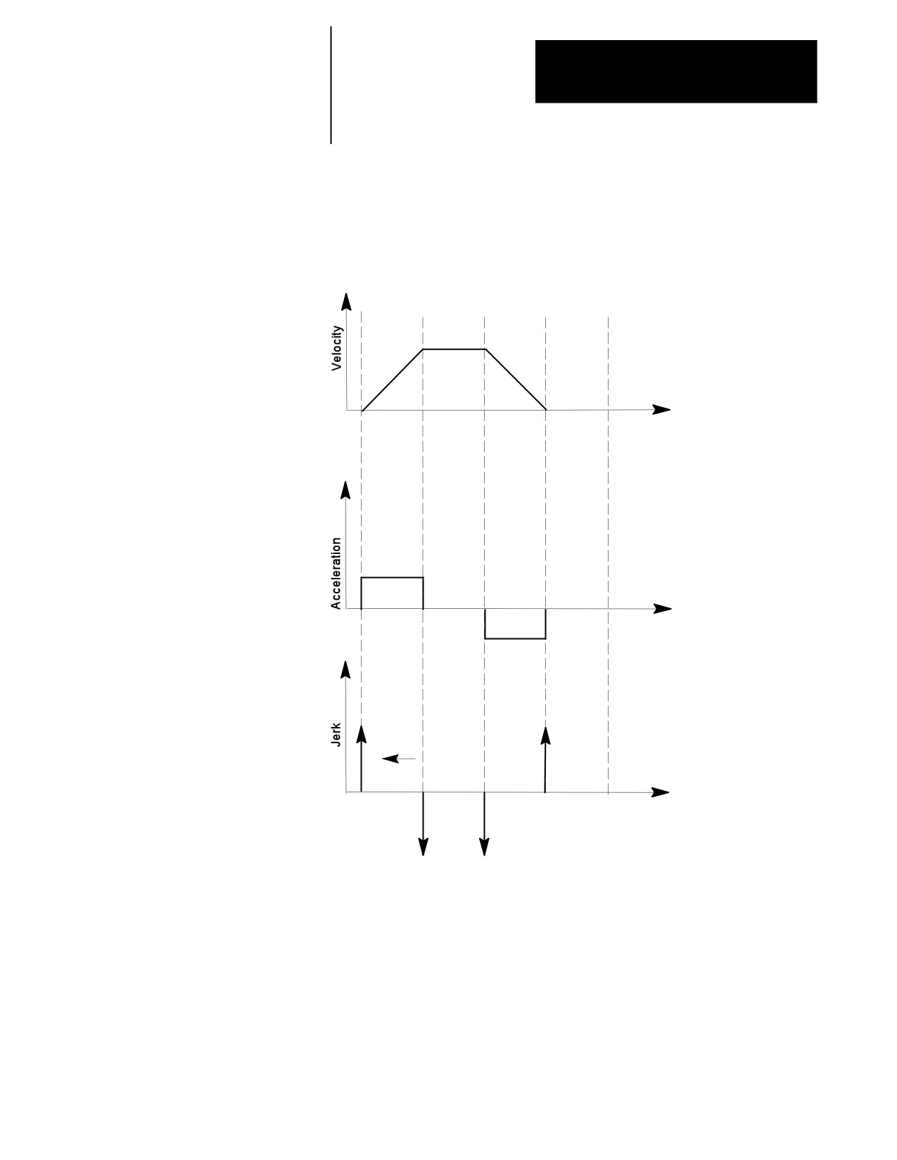
Axis motion response lag can be minimized by using Linear Acc/Dec for
the commanded feedrates. The system installer sets Linear Acc/Dec values
Linear Acc/Dec
for interpolation for each axis in AMP. Figure 18.7 shows axis motion
using Linear Acc/Dec.
Figure 18.7
Linear Acc/Dec
Time
Time
Jerk is
Infinite
Time
18-13
Chapter 18
Programming Feedrates
18.3.3
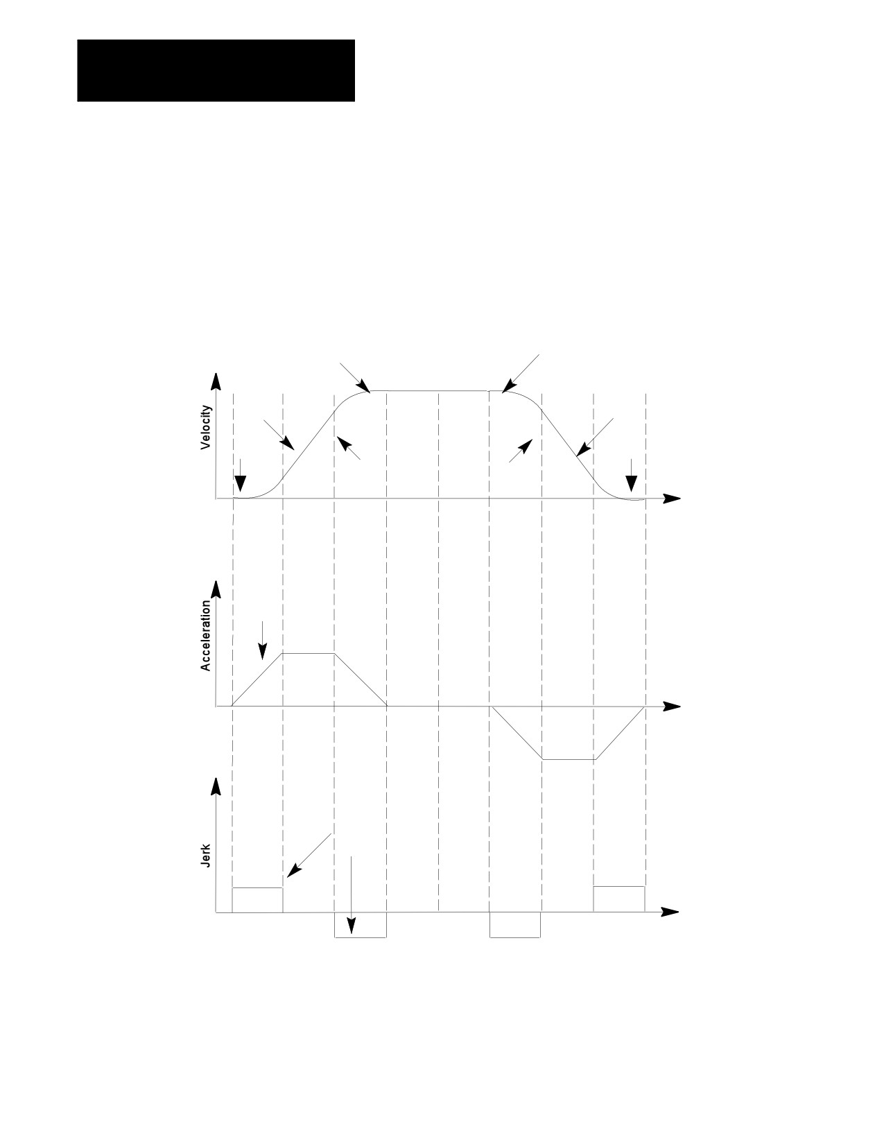
When S--Curve Acc/Dec is enabled, the control changes the velocity
profile to have an S--Curve shape during acceleration and deceleration
S-Curve Acc/Dec
when in Positioning or Exact Stop mode. This feature reduces the
machine’s axis shock and vibration for the commanded feedrates.
Figure 18.8 shows axis motion using S--Curve Acc/Dec.
Figure 18.8
S-Curve Acc/Dec
S--Curve
S--Curve
Acceleration
Deceleration
Commanded
Feedrate
Linear
Linear
Acc
Dec
Jerk
Jerk
Jerk
Jerk
Time (sec)
Acceleration
Ramp
Time (sec)
Jerk
Time (sec)
18-14
Chapter 18
Programming Feedrates
18.3.4
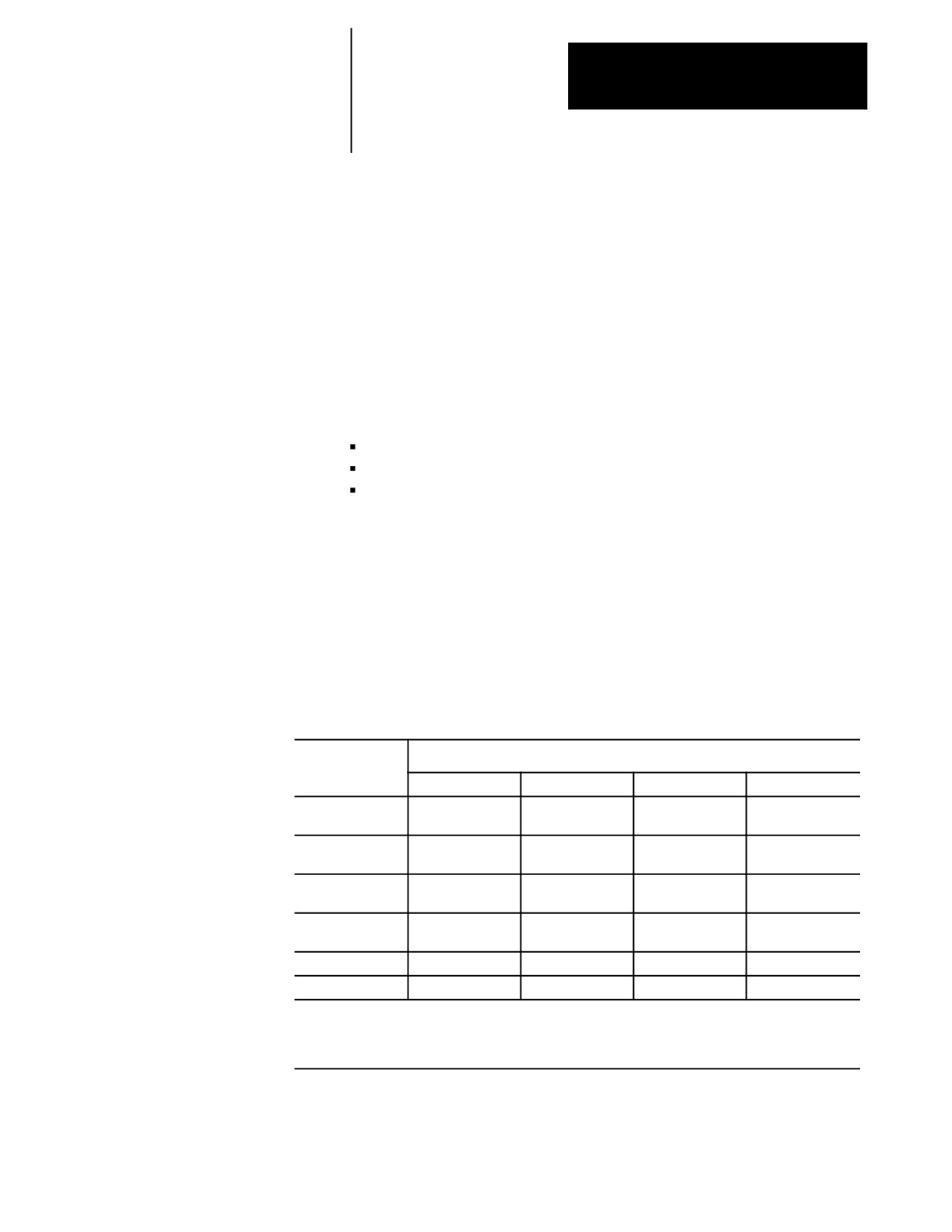
Programmable Acc/Dec allows you to change the Linear Acc/Dec modes
and values within an active part program via G47.x and G48.x codes.
Programmable Acc/Dec
You cannot retrace through programmable acc/dec blocks (G47.x and
G48.x). However, you can retrace through blocks where programmable
acc/dec was already active.
Selecting Linear Acc/Dec Modes (G47.x - - modal)
Programming a G47.x in your part program allows you to switch Linear
Acc/Dec modes in nonmotion blocks. If S--Curve Acc/Dec is active, all
positioning moves within fixed cycles will use this mode.
G47 -- Linear Acc/Dec in All Modes
G47.1 -- S--Curve Acc/Dec for Positioning and Exact Stop Mode Only
G47.9 -- Infinite Acc/Dec (No Acc/Dec) (Enabled by your system
installer in AMP)
Important: For optimum S--Curve Acc/Dec functionality, any block
preceding a G47.1 block will decel to 0.
The table below shows you the interaction between contouring,
positioning, exact stop moves, and acc/dec type (i.e., linear, exponential,
S--Curve, and disabled).
Table 18.A
Interaction Between Contouring, Positioning, Exact Stop, and
Acc/Dec Modes
Programming:
In this mode will result in:
G00
G01
G02
G03
G47
Linear/
Linear
Linear
Linear
Exponential1
G47 & G09/G61
Linear/
Linear
Linear
Linear
Exponential1
G47.1
S--Curve/
Linear
Linear
Linear
Exponential2
G47.1 & G09/G61
S--Curve/
S--Curve
Linear
Linear
Exponential2
G47.9
Disabled
Disabled
Disabled
Disabled
G47.9 & G09/G61
Disabled
Disabled
Disabled
Disabled
1Linear/Exponential is a function of Positioning Acc/Dec. If Exponential is AMPed, this is the acc/dec type,
otherwise, the type is Linear.
2S--Curve/Exponential is a function of Positioning Acc/Dec. If Exponential is AMPed, this is the acc/dec type,
otherwise, the type is S--Curve.
18-15
Chapter 18
Programming Feedrates
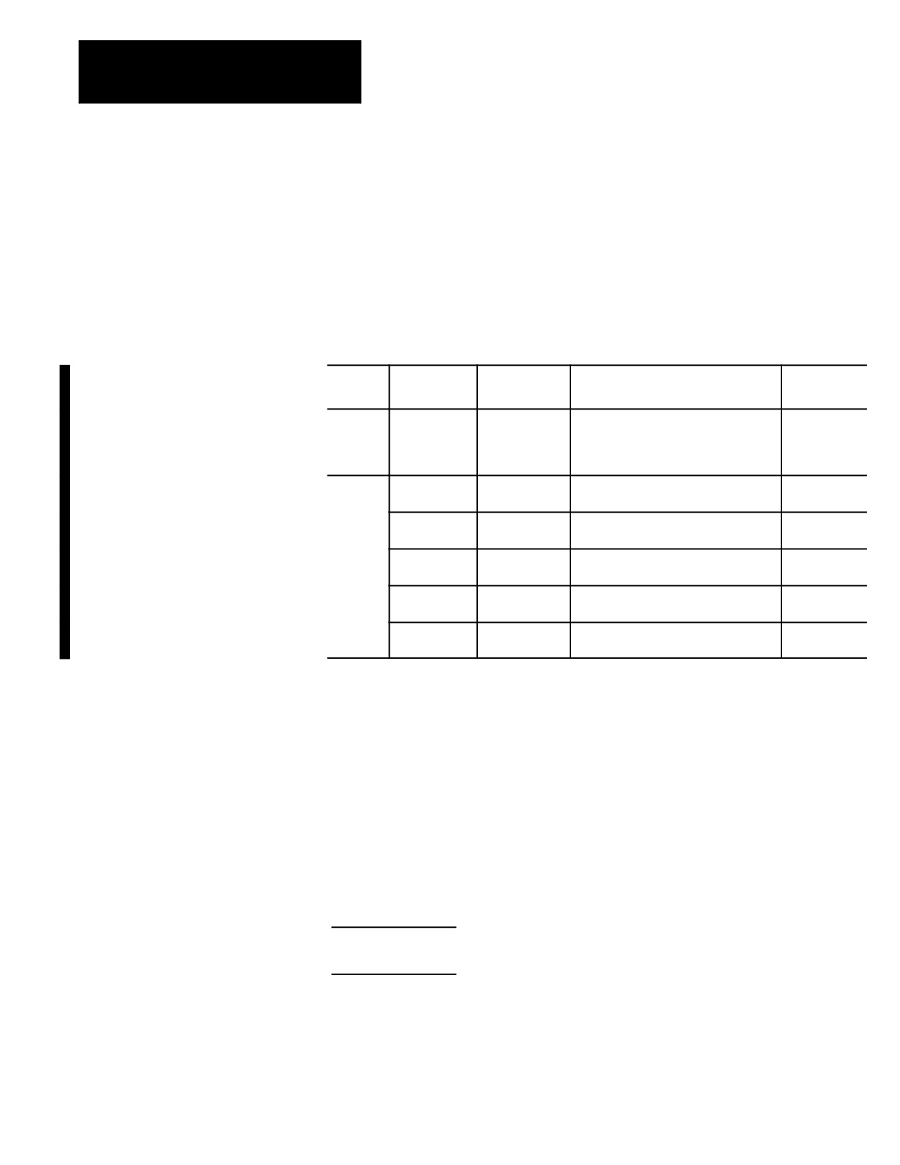
Selecting Linear Acc/Dec Values (G48.n - - nonmodal)
Programming a G48.x in your part program allows you to switch Linear
Acc/Dec values in nonmotion blocks. Axis values in G48.n blocks will
always be treated as absolute, even if the control is in incremental mode.
Below is the format for calling G48 commands. Use this format with the
axis names assigned by your system installer:
G48.n X_Y_Z_
Where :
In this mode :
Units of
Sets up :
Macros :
measure :
XYZ
G48
N/A
acceleration, deceleration, and jerk
N/A
ramps back to the AMPed values
Important: All axis words in a G48 are
ignored.
XYZ
G48.1
in./sec2 or
acceleration ramps for Linear Acc/Dec
#5631 to 5642
mm/sec2
mode
G48.2
in./sec2 or
deceleration ramps for Linear Acc/Dec
#5651 to 5662
mm/sec2
mode
G48.3
in./sec2 or
acceleration ramps for S--Curve Acc/Dec
#5671 to 5682
mm/sec2
mode
G48.4
in./sec2 or
deceleration ramps for S--Curve Acc/Dec
#5691 to 5701
mm/sec2
mode
G48.5
in./sec3 or
jerk limits
#5711 to 5722
mm/sec3
Important: The allowable programmed range for the axis word depends
on the configured format. If you exceed these allowable ranges set by your
system installer, you may use paramacros to override this limit.
For example, if the allowable programmed range for the axis word is 3.4
(e.g., 999.9999 max input) and the desired jerk limit is 100,000 mm/sec3,
you may set Paramacro #1 to 100,000 and program a G48.5 X#1 to set the
jerk limit to 100,000. This method can be used for any of the G48
programming blocks.
Example 18.1
Allowable Programmed Range
#1 = 100000;
G48.5 X #1;
Important: The part program G48.n adjustments to Acc/Dec Ramps are
not applied to jog moves. The AMPed Linear Acc/Dec mode rates are
used when Manual Acc/Dec mode is linear.
18-16
Chapter 18
Programming Feedrates
18.3.5
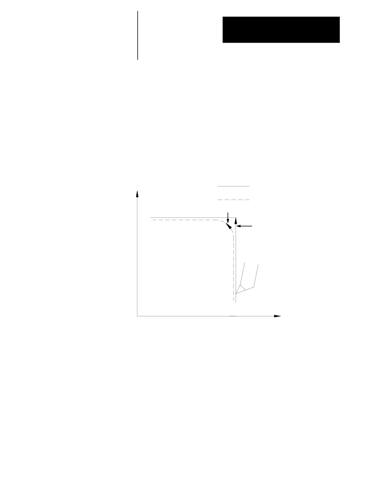
When Acc/Dec is active, the control automatically performs Acc/Dec to
give a smooth acceleration/deceleration for cutting tool motion.
Precautions on Corner
Cutting
However, there are cases in which Acc/Dec can result in rounded corners
on a part during cutting. In Figure 18.9, this problem is obvious when the
direction of cutting changes from the X axis to the Z axis. In this case, the
X axis decelerates as it completes its move, while the Z axis is at rest. As
soon as the X axis reaches the AMP defined in-position band, the Z axis
begins accelerating to make its commanded move. Since the Z axis begins
motions before the X axis finishes, a slight rounding results.
Figure 18.9
Rounding of Corners
X
Programmed tool path
Actual tool path
G64, G63
G09, G61
Cutting tool
Z
Use these G-codes to eliminate corner rounding:
Exact Stop (G09 - - non-modal)
If a programmed motion block includes a G09, the axis moves to the
commanded position, decelerates, and comes to a complete stop before the
next axis motion block is executed. The G09 can be programmed in rapid
(G00), feedrate (G01), or circular (G02/G03) motion blocks, but it is active
only for the block in which it is programmed.
18-17
Chapter 18
Programming Feedrates
Exact Stop Mode (G61 - - modal)
G61 establishes the exact stop mode. The axes move to the commanded
position, decelerate and come to a complete stop before the next motion
block is executed. To cancel this mode, program G62, or G63.
Cutting Mode (G64 - - modal)
G64 establishes the cutting mode. This is the normal mode for axis motion
and is generally selected by your system installer as the default mode
active on power up. Block completes when the axes reach the interpolated
endpoint. To cancel this code, program G61, G62, or G63.
Tapping Mode (G63 - - modal)
In the G63 tapping mode, the feedrate override value is fixed at 100
percent, and a cycle stop is ignored. Axis motion commands are executed
without deceleration before the end point. The program proceeds to the
next block without checking in position status, similar to the operation of
G64. To cancel this code, program G61 or G62.
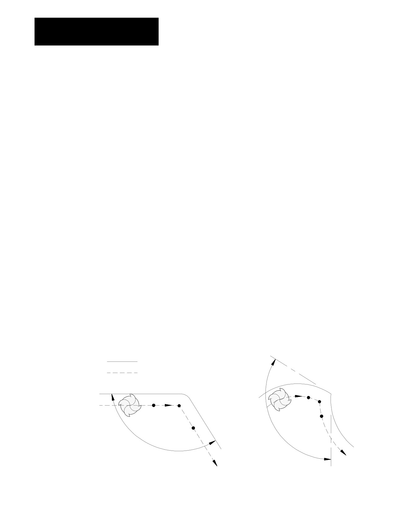
Automatic Corner Override (G62 - - modal)
In cutter compensation mode (G41/G42), the load on the cutter increases
while moving inside a corner. If the G62 automatic corner override mode
is active, the control automatically overrides the programmed feedrate to
reduce the load on the cutter. To cancel this code, program G61 or G63.
Figure 18.10
Automatic Corner Override (G62)
programmed tool path
tool center path
a b
a
b
c
A
c
A
18-18
Chapter 18
Programming Feedrates
When the corner angle, A, is larger than the value set for “min. angle for
corner override” in AMP, the programmed feedrate is overridden from
point “a” to point “b,” and from point “b” to point “c.”
The system installer sets these values in AMP:
Min angle for corner override -- minimum angle (A) between
programmed paths before corner override is activated
Corner override distance (DTC) -- vector distance from, and of current
move (b) to point on programmed path (a) where corner override is
activated
Corner override distance (DFC) -- vector distance from end of current
move (b) to point on programmed path (c) where corner override is
deactivated
Corner override percent -- amount that feedrate is to be reduced once
corner override is activated
To use an exact stop function while the automatic corner override mode
(G62) is active, use the G09 instead of the G61. This is because G61 and
G62 belong to the same G modal group and cancel each other if
programmed. Be aware that G09 is non-modal.
18.3.6
Your system installer has the ability to change the rate in which a spindle is
Spindle Acceleration (Ramp)
accelerated. AMP allows the option of either a 20 millisecond ramp (2ms
intervals) or an immediate step in spindle speed. By writing the
appropriate PAL your system installer may also in effect generate a spindle
“ramp” for even smoother spindle acceleration. Refer to documentation
prepared by your system installer.
18.3.7
In the default mode (G36), the Acc/Dec feature sometimes limits axis
feedrates far below the programmed feedrate. This occurs when the length
Short Block Acc/Dec Check
of axis motion in a block is short relative to the length of time necessary to
G36, G36.1
accelerate and decelerate the axis.
In the default mode (G36), the control limits the axis feedrate in any block
to the maximum speed from which it can properly decelerate to a stop
before that block ends. For example, consider the velocity profile of an
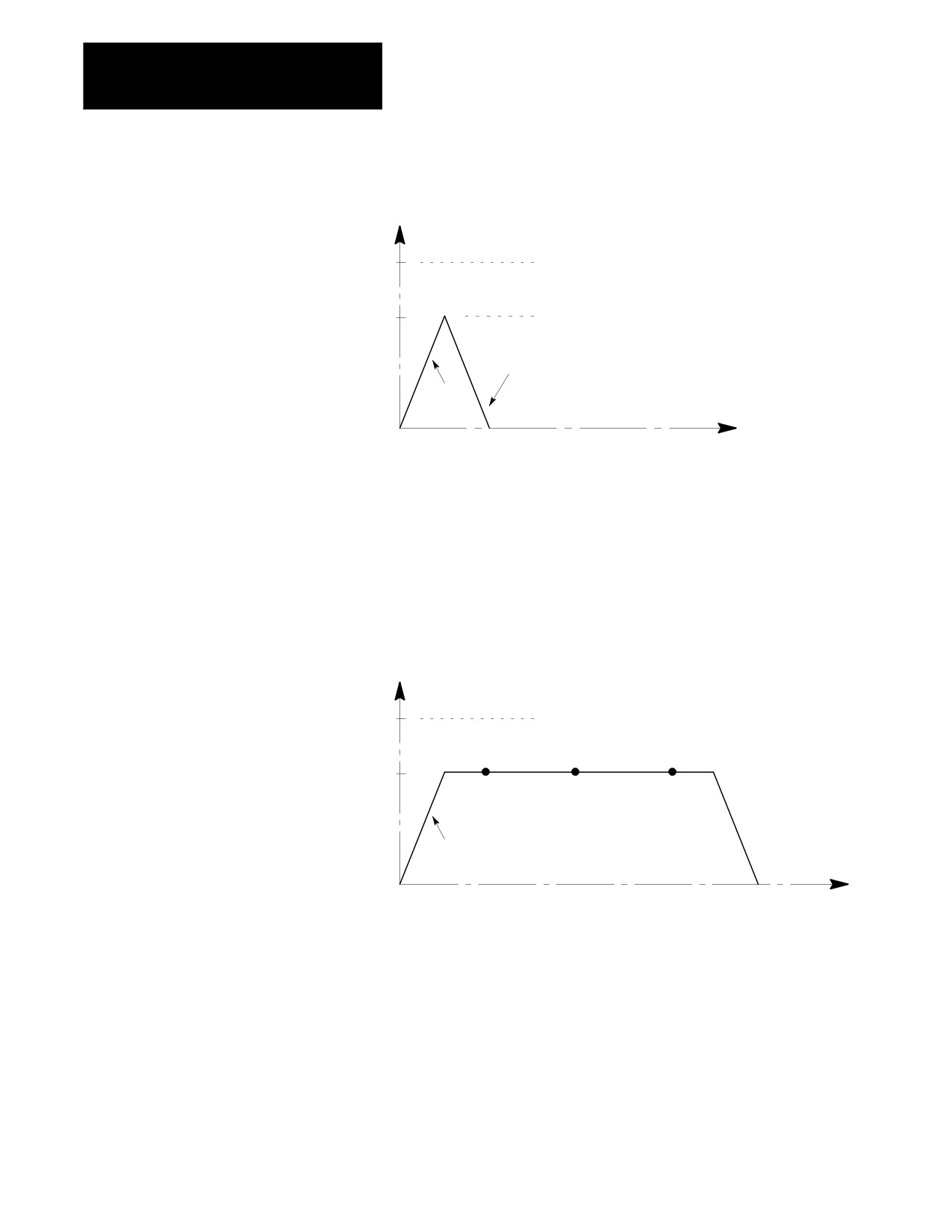
axis moving from Z4.8 to Z4.9 in Figure 18.11.
18-19
Chapter 18
Programming Feedrates
Figure 18.11
Programmed Feedrate Not Reached
F100
Programmed
Z
feedrate
F
Feedrate clamped here to allow
E
F60
time for deceleration
E
D
R
Linear
A
Deceleration
Linear
T
E
Accel
Z4.8
Z4.9
Z5.0
Z5.1
12162-I
DISTANCE
Normally this causes no problem. However, in cases where a series of
very short axis moves in separate blocks exist, this limitation to the
feedrate can cause finish problems as well as increased cycle time.
Figure 18.12 shows the velocity profile that would result from a series of
short Z axis moves from 4.8 to 4.9 to 5.0 to 5.1 to 5.2.
Figure 18.12
Feedrate Limited Because of a Series of Short Moves
F100
Programmed
Z
feedrate
F
Feedrate clamped
E
F60
E
D
R
A
Linear
T
E
Acceleration
Z4.8
Z4.9
Z5.0
Z5.1
Z5.2
DISTANCE
12163-I
18-20
Chapter 18
Programming Feedrates
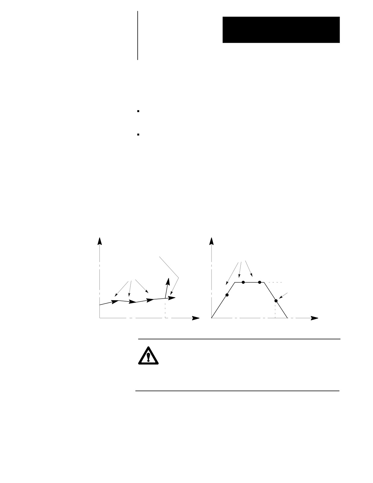
To avoid this feedrate limitation, the short block Acc/Dec clamp can be
disabled by programming a G36.1. In this mode, the control assumes that
no rapid decelerations are required and allows axis velocities to go higher
than they otherwise would. Activate G36.1 mode only when:
no sudden changes in programmed feedrate within consecutive short
motion blocks exists (this includes requesting a feedhold or cycle stop)
no drastic change in programmed direction is present within the short
blocks
If any of these conditions are not met during the G36.1 mode, the control
can overshoot positions since the axes do not have time to decelerate. For
example, consider the following position and velocity plots if a drastic
change in direction is requested after the move from Z5.0 to Z5.1 when in
G36.1 mode (see Figure 18.13) . The position Z5.1 is overshot and the
axis would have to reverse direction to reach proper position.
Figure 18.13
Drastic Change in Direction while in Short Block Mode (G36.1)
Z-axis overshoots endpoint of
move because of drastic change
Series of short
in programmed direction.
Z
move blocks.
X
F
Series of short
E
move blocks.
E
Programmed Feedrate
D
R
X1.9
Deceleration
Z-axis is traveling too
A
fast to stop when end
T
Acceleration
of move is reached.
X1.8
E
Z4.8
Z4.9
Z5.0
Z5.1
Z
Z4.8
Z4.9
Z5.0
Z5.1
DISTANCE
12164-I
CAUTION: The programmer must consider the direction and
feedrate transitions from block to block when the short block
Acc/Dec check is disabled (G36.1 mode). If the transition
exceeds the deceleration ramp of the axis, damage to the part or
equipment can occur.
18-21
Chapter 18
Programming Feedrates
G36 and G36.1 are modal. The control should only be in short block
check disable mode (G36.1) when executing a series of fast short blocks
that contain only slight changes in direction and velocity. What constitutes
a slight change in direction and velocity depends on the Acc/Dec ramp
configured for your machine.
G36 -- Short Block Acc/Dec clamp Enable
G36.1 -- Short Block Acc/Dec clamp Disabled
G36 is the default mode, and it is established at power-up, E-STOP reset,
and end of program (M02, M30, or M99). The recommended method of
programming G36 and G36.1 is to program a relatively long entry and exit
move into and out of the mode.
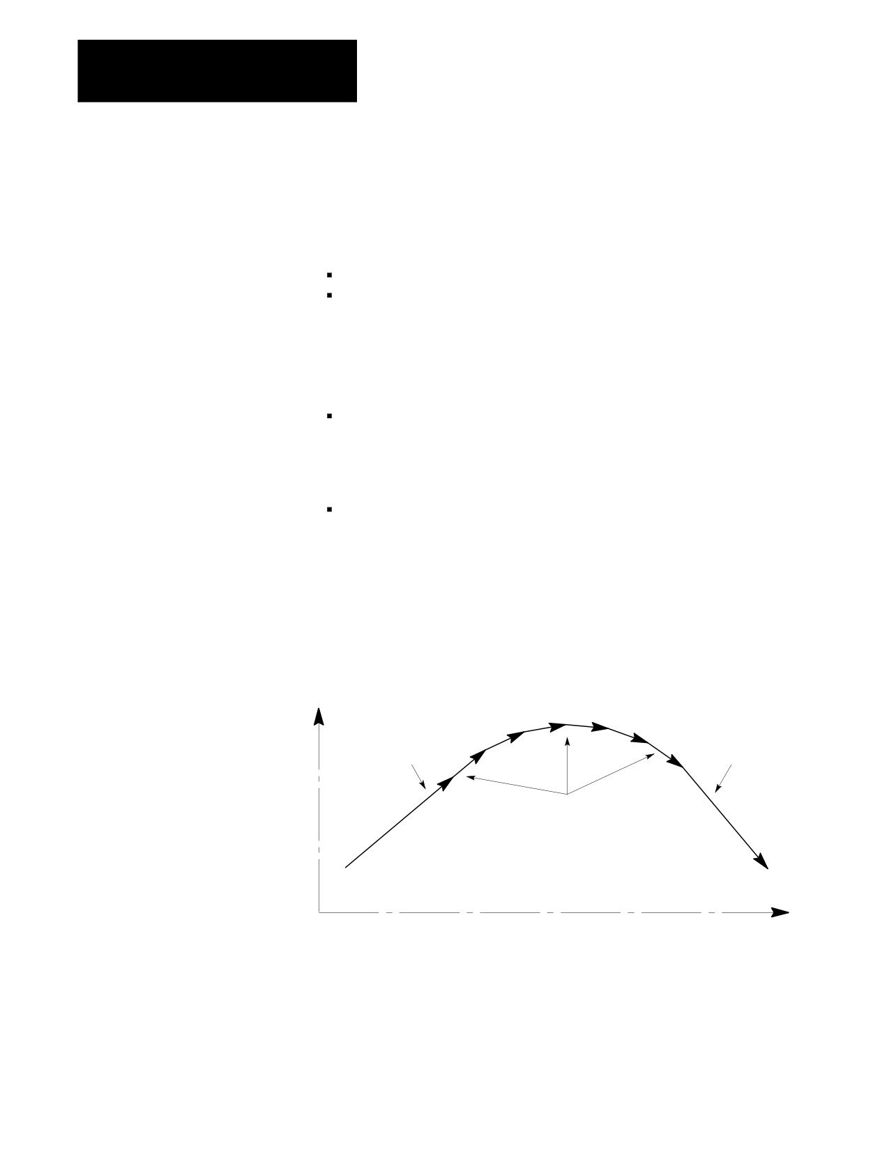
The entry move should be a long move, in the general direction of the
first short move, and at the same feedrate as the first short move. This
entry move should be long enough for the axes to reach programmed
speed. Program the G36.1 code in this entry block
The exit move should be a long move, in the general direction of the
last short move, and at the same feedrate as the last short move. This
exit move should be long enough for the axes to decelerate properly
without overshooting their end points. Program the G36 code in this
exit block
Figure 18.14 shows the recommended entry and exit moves for short block
Acc/Dec clamp disable mode.
Figure 18.14
Entry and Exit Move to/from Short Block
Long Entry move.
Long Exit move.
X
This block contains a
This block contains
G36.1 command
a G36 command
Series of short move blocks
Z
12165-I
END OF CHAPTER
18-22
Chapter
19
Dual Axis Operation
19.0
The Dual Axes feature lets the part programmer simultaneously control
multiple axes while programming commands for only one. It differs from
Chapter Overview
the split axis feature of the 9/Series control in that the split axis feature is
used to control a single axis positioned by two servo motors.
This chapter reviews the following major dual axis operations:
Topic:
On page:
Parking a dual axis
19-3
Homing a dual axis
19-4
Programming a dual axis
19-5
Offset management
19-7
The dual axes feature is especially useful for lathes with dual turrets and
other machines running with parallel cutting tools. Figure 19.1 shows a
typical configuration for dual axes.
Implementation of the dual axis feature can require significant PAL
modification as well as proper AMP configuration. The dual axis feature
is an option. Refer to your system installer’s documentation to see if the
dual axis option has been purchased for your machine.
19-1
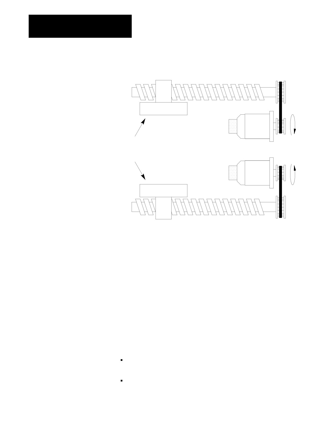
Chapter 19
Dual Axis Operation
Figure 19.1
Dual Axis Configuration
Lead screw
Axis 1
Encoder
Servo
motor
Dual Axes - two completely
separate axes responding to
the same programming
commands.
Encoder
Servo
motor
Axis 2
Lead screw
The 9/Series control can support two dual axis groups. A dual axis group
consists of two or more axes coupled through AMP and commanded by a
master axis name. The master axis name is used by the part programmer
or operator when commanding the dual axis group in part programs or for
jog moves.
Each axis that makes up a dual group is controlled by a separate
positioning command from the servo module. This dual group command
is based on the move generated by the control when the master axis is
commanded to a position.
All axes that make up a dual group reach end-points at the same time. This
requires that all axes that make up a dual axis group share the same
feedrate parameters, acc/dec ramps, and other axes specific data for the
group.
This section requires that you understand these terms:
Master Axis -- A master axis is the name used to command the axes in a
dual group.
Dual Group -- A dual group is a set of axes that are coupled together in
AMP and commanded by a single master axis name.
19-2