9/Series CNC Lathe. Operation and Programming Manual - page 14
Chapter
16
Chamfering and Corner Radius
16.0
During cornering, the 9/Series control has the option of performing either a
chamfer (a linear transition between the blocks) or a corner radius (an arc
Chapter Overview
transition between blocks).
,C
Chamfer size
This word is used to define a chamfer length that connects two
intersecting tool paths. This word determines the distance that
the chamfer begins and ends from the tool paths intersection.
,R
Corner radius
This word is used to define the radius of an arc that is tangent
to two intersecting tool paths.
This chapter describes chamfering and corner radius in detail. Major
topics include:
Topic:
On page:
Chamfering
16-2
Corner radius
16-4
Both the chamfer and the corner radius features are generated between two
motion blocks that must be programmed in the same plane. The motion
block with the corner chamfering (,C) or the corner radius (,R) word is
defined as the first cornering block. The next motion block in the
cornering plane is defined as the second block.
If more than one ,C- or ,R-word is programmed in the same block, only the
right-most word is used; others are ignored. The second block can also
have a corner chamfering or corner rounding word in it. If it does, the
second block is also used as the first block of the next corner chamfering
or corner rounding.
CAUTION: If you make a programming error of some type is
made in the block defining the second tool path in the chamfer
or radius blocks, the control is not able to cut the correct
chamfer or radius. Instead, the first block is executed to its
programmed endpoint. This can cause damage to the part or
cutting tool.
16-1
Chapter 16
Chamfering and Corner Radius
There is a limit of 4 non-motion blocks allowed between the first and
second motion blocks defining the corner transition. A non-motion block
is any block that does not generate axis motion in the currently active
plane. The control generates an error if more than 4 non-motion blocks are
programmed between the cornering plane.
Use the chamfering and corner radius features are often used in
conjunction with QuickPath Plus. They can be programmed in either
absolute (G90) or incremental (G91) modes.
16.1
Program a chamfer size following the address ,C to cut a chamfer between
Chamfering
consecutive tool paths. The chamfer word must follow a comma (,) and is
programmed in the first of two paths connected by the chamfer. The value
following the ,C address is the amount of tool path cut of each
programmed tool path by the chamfer. The angle that the chamfer makes
with the tool paths is dependant on the size of the chamfer.
Measure the chamfer size from the intersection of the two blocks.
If the block:
Then:
linear
distance programmed with the ,C-word is measured from the
intersection of the two tool paths along the linear path.
circular
then the chamfer distance programmed is applied as a chord length
on the arc measured from the intersection between the two blocks.
This applies regardless of the combination of arcs and lines to be
chamfered.
The ,C-word can be programmed any where in a block as long as no space
is programmed between the comma and the chamfer distance.
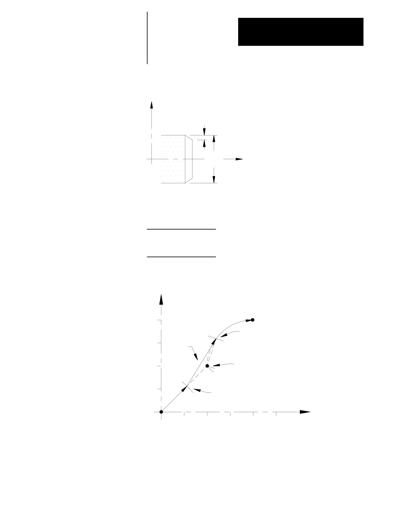
Example 16.1
Basic Chamfering Using ,C
N10 Z25.0 X0.0 F.1.;
N20 G01X20.,C5.0;
N30 Z5.0;
16-2
Chapter 16
Chamfering and Corner Radius
Figure 16.1
Results of Chamfering Using ,C from Example 16.1
X
2.0
20.0
Z
Example 16.2
Linear to Circular Motions with Chamfer
N10X0.Z0.F.1;
N20X10.Z10.,C5;
N30G02X20.Z20.R10;
Figure 16.2
Results of Linear to Circular Motions with Chamfer, Example 16.2
X
20
N30
Actual start point of
Chamfer
block N30 and end
15
point of chamfer block
block
C (chord length)
Programmed end point
10
of block N20
C
5
N20
Actual end point of block N20 and
start point of chamfer block
Z
5
10
15
20
25
16-3
Chapter 16
Chamfering and Corner Radius
16.2
Use the ,R command to program a radius between two intersecting tool
paths. The R command must be programmed after a comma (,). Program
Corner Radius
the ,R followed by the radius size in the block where the first path is
programmed. The control looks ahead to the block commanding the
second path and automatically inserts the circular rounding bock to meet
that path. This inserted circular block is always tangent to both
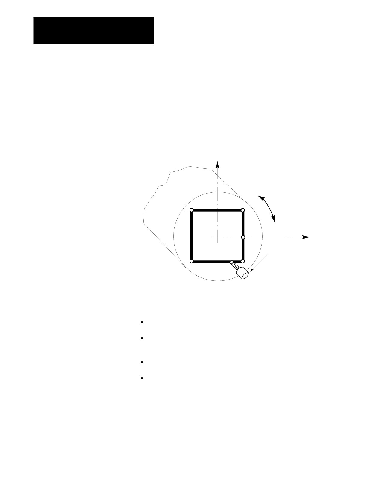
programmed tool paths. If the control cannot generate an arc that is
tangent to both paths with the programmed ,R, then the control generates
an error.
Block:
Description:
The first corner radius
always terminates at the point on the block where the rounding block
is tangent to the first block
The rounding
terminates at the point where the generated rounding block is tangent
to the second rounding block.
The second rounding
starts from the end point of the generated circular block and continues
on to the programmed end point of the second block.
The R-word can be programmed any where in a block as long as no space
is programmed between the ,R and the radius length.
Important: If the two motion blocks are tangent to each other, then any
corner rounding commands are ignored.
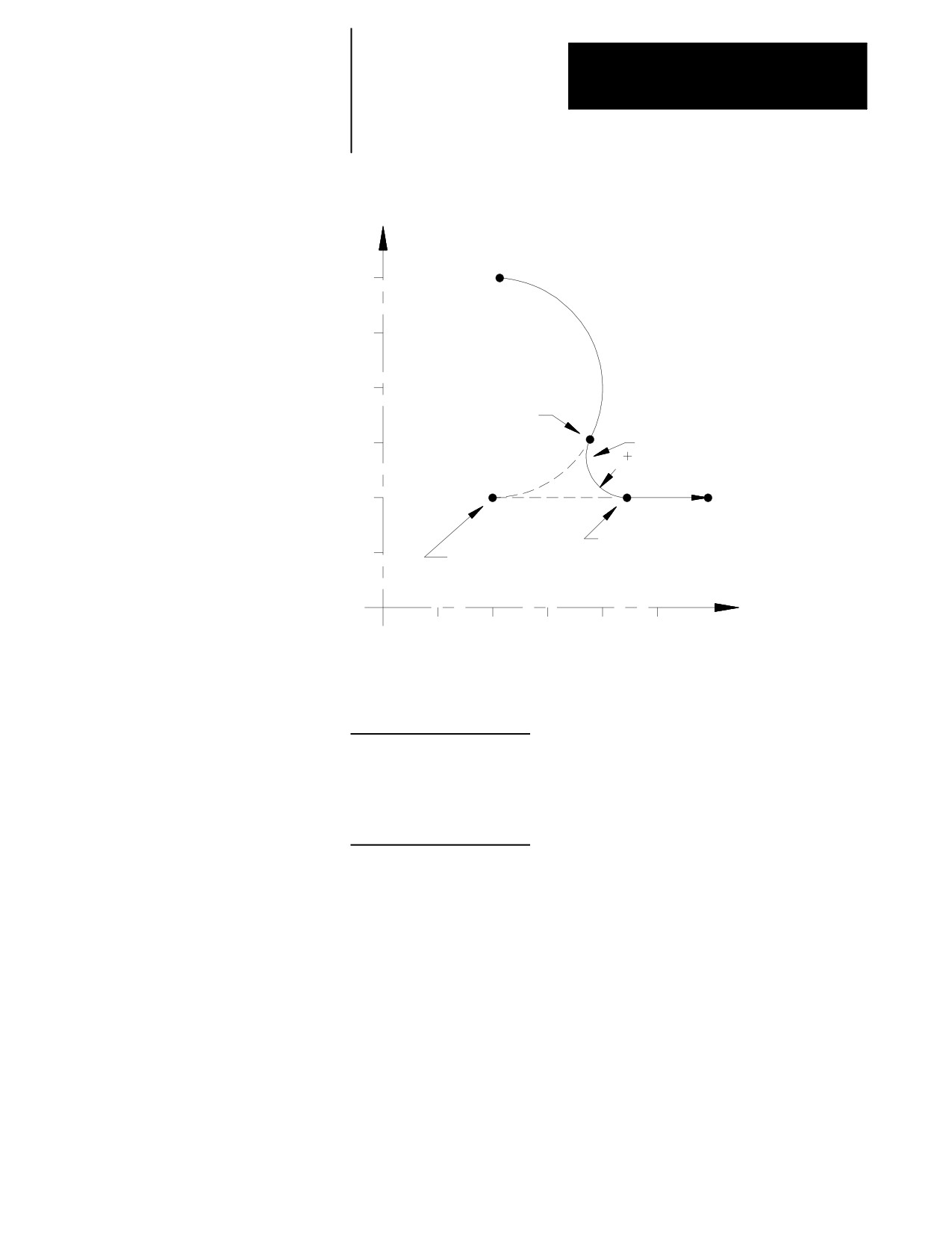
Example 16.3
Programming a Radius for a Circular Path into a Linear path.
N10Z10X30.F.1;
N20G02X10.Z10.R10,R3;
N30Z30.X10.;
16-4
Chapter 16
Chamfering and Corner Radius
Figure 16.3
Results of Radius for a Circular Path into a Linear path, Example 16.3
X
30
25
N20
Actual end point of
20
block N20 and start
point of corner block
15
Corner block
R
N30
10
Actual start point of
5
Programmed end
block N30 and end
point of block N20
point of corner block
Z
5
10
15
20
25
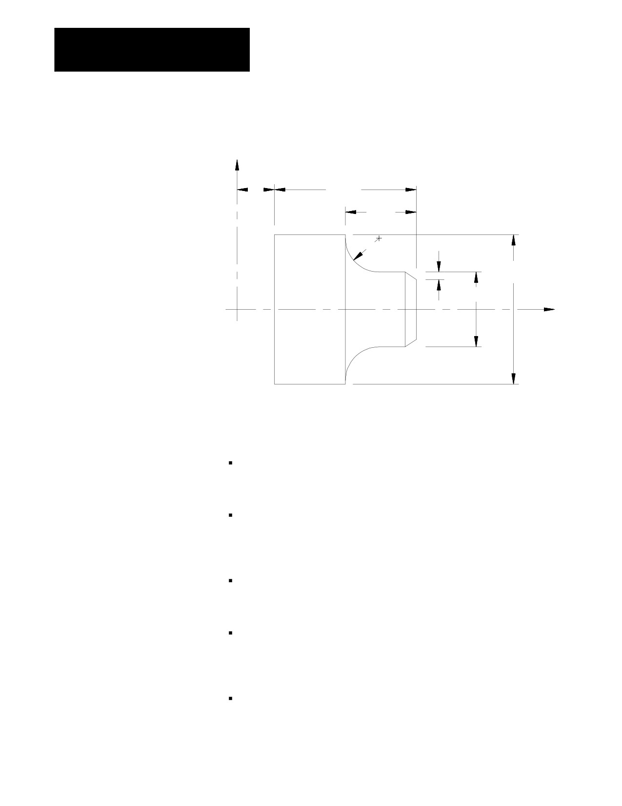
Example 16.4
Radius and Chamfer with QuickPath Plus
N10Z25.X0.F.1;
N20G01A90,C2.;
N30Z15.X20.A180,R5.;
N40X40.;
N50Z5.;
16-5
Chapter 16
Chamfering and Corner Radius
Figure 16.4
Results of Radius and Chamfer, Example 16.4
X
5.0
20.0
10.0
R 5.0
2.0
40.0
20.0
Z
16.3
When using chamfering and corner radius, remember:
Considerations with
If the control is executing in single block mode, the control enters the
Chamfering and Corner
cycle stop state after executing the first block and the adjacent chamfer
Radius
or corner radius.
If non-motion blocks are programmed separating the two intersecting
blocks for the corner radius and chamfer features, the control executes
the chamfer or radius immediately after the first block. The non-motion
blocks are executed after the control has executed the chamfer or radius.
Any negative signs programmed with the ,C- or ,R-words are ignored.
Use the absolute value of the word to cut the chamfer or radius. For
example ,C-10 is used as ,C10.
An error is generated if the length of a chamfer is larger than the
programmed length of the first or second move, or for corner rounding
if the programmed corner radius is so large that the tangent point on
both of the two programmed blocks does not exist.
An error is generated if you attempt to change planes between blocks
that are chamfer or corner radius blocks.
16-6
Chapter 16
Chamfering and Corner Radius
You must program ,C and ,R in blocks that contain axis motion in the
current plane. If they are programmed in a block that does not contain
axis motion in the currently active plane, the control generates an error.
,C and ,R cannot be programmed in a block that contains any of the
following:
- Any fixed cycle G-codes
- Any dwell commands
- Thread cutting blocks
- Programmable zone G-codes
Your system installer determines in AMP the resolution of the ,C- and
,R-words for both inch and metric programming. Refer to
documentation prepared by your system installer for details.
END OF CHAPTER
16-7
Chapter
17
Spindles
17.0
This chapter describes spindle speed control, orientation, and direction, and
the virtual C axis.
Chapter Overview
Topic:
See page:
Spindle Speed Control
17-1
Controlling Spindles (G12.1, G12.2, G12.3)
17-9
Spindle Orientation (M19, M19.2, M19.3)
17-10
Spindle Direction (M03, M04, M05)
17-12
Virtual C Axis
17-13
Synchronized Spindles
17-23
If you are using a dual-processing system, spindle control is different.
Refer to page 30-13 for details.
17.1
Relative speed of the revolving workpiece to the cutting tool tip is referred
Spindle Speed Control
to as the cutting speed. Required cutting speeds can be attained by
designating proper spindle speeds. Figure 17.1 illustrates the relationship
between workpiece diameter (D), spindle speed (N) and cutting speed (V).
Figure 17.1
Relationship between Cutting Speed, Spindle Speed, and Diameter
Nrpm
Chuck
Vm/min
D Diameter
Workpiece
17-1
Chapter 17
Spindles
In this case, cutting speed V is expressed with this equation:
V = (3.14159)(D)(N)/1000
To cut a 150-mm-diameter workpiece at a cutting speed of 200 m/min, the
spindle speed to provide the required cutting speed is calculated to be
approximately 1325 rpm using the above equation. This means that by
designating “S1325;” in a part program, cutting is conducted at a cutting
speed of 200 m/min.
When cutting tapers, which have different workpiece diameters at different
cutting points, spindle speeds need to vary during the cutting process to
maintain proper cutting speed. To compensate for this problem, the control
has a feature to allow designating the required cutting speed V, directly in a
part program. With this feature, the control changes spindle speed as the
diameter of the workpiece changes to maintain a fixed cutting speed. This
feature is referred to as the “constant surface speed mode” or CSS.
The spindle function has two modes:
Constant Surface Speed Mode (G96) maintains a workpiece’s speed
across a tool equal to a desired cutting speed dependent on the working
diameter. See page 17-3.
Constant Spindle RPM Mode (G97) maintains a constant spindle speed
equal to the programmed S-word making cutting speed independent of
the working diameter. See page 17-9.
Spindle Speed (S-word)
Use the S-word to program the spindle speed for all configured spindles.
The common S-word can be applied per spindle by associating the S-word
in the same block with the spindle directional M-codes. See page 17-12
for information about spindle directional M-codes. If no directional
M-code is programmed in the block with the S-word, then the S-word is
applied to the active controlling spindle.
CAUTION: The displayed S-word always shows the
controlling spindle’s programmed spindle speed. When the
non-controlling spindles are configured, their S-word display
must be handled by some other means. See the system
installer’s documentation for display capabilities of the active
spindle speed for auxiliary spindles.
17-2
Chapter 17
Spindles
The S-word units represent revolutions per minute (RPM) in most cases.
Only during CSS programming are the S-word units different. While CSS
mode is active, the S-word units represent surface feet per minute. Only
the controlling spindle can change its S-word mode from RPM to CSS.
17.1.1
The G96 command maintains a constant cutting speed (programmed by the
S parameter) by monitoring the cutting tool’s position with respect to the
Constant Surface Speed
center line of the spindle.
Mode (G96)
In the G96 mode the S-word is used to program the cutting speed. Actual
units for the S-word are surface meters per minute in metric or surface feet
per minute in the inch system. To maintain a cutting speed of 200 m/min,
for example, write the program as:
G96 S200;
G96 mode must also first be enabled by programming an M58 code. See
the notes on CSS on page 17-6 for details. The G96 code is modal and
remains active until it is cancelled by the G97 code or disabled with an
M59 code.
Important: When changing from G97 to G96 mode, if an S-word is
specified in the G96 block, the cutting speed changes to the value indicated
by the S-word. If no S-word is contained in the G96 block the control uses
the current cutting speed of the tool as the CSS cutting speed. The spindle
speed then changes relative to the tool position to maintain this CSS
cutting speed.
Important: The system installer determines in AMP what axis is used to
determine the cutting diameter. The programmer has the option of
changing the diameter axis by programming a P-word when in the G96
mode. P-words range from P1 to P9. A P-word to change diameter axis
may be programmed in any block where in the G96 mode as long as that
block does not contain a dwell. Refer to the system installer’s
documentation for details on what P-word programs the axis that is
perpendicular to the part diameter. Normally the P-word is not
programmed for CSS. If not programmed the system installer’s default
axis is used. This manual assumes the X axis determines the cutting
diameter.
Your system installer determines CSS axis assignment in AMP. You can
change the CSS axis by programming a P-word (P0 through P9) in the
G96 block when activating CSS.
17-3
Chapter 17
Spindles
Each P-word corresponds to a specific axis assigned to it in AMP. Any
CSS axis changes made by programming a P-word in the G96 block
remain in effect regardless of what mode the control is in. The default
CSS axis is assigned to P0 and is active on power-up and after a control
reset.
Use this equation to calculate constant surface speed:
N = K V/D
RPM = Surface speed per minute / (.262 x diameter)
Where :
Is :
N
Spindle speed (rpm)
K
Constant 318.31 (1000/p) for metric system or 3.8197 (12/p) for inch system
V
Surface speed (m/min or feet/min)
D
Cutting diameter (mm or inch)
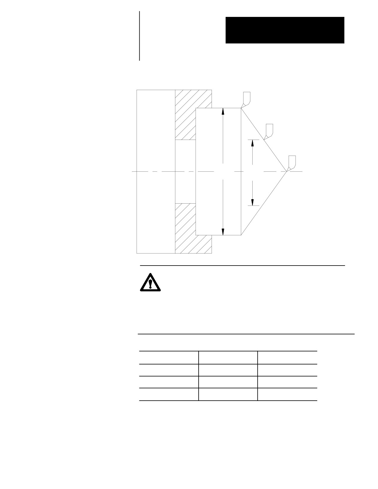
Figure 17.2 shows how the spindle speed changes as the cutting diameter
changes when:
constant K is 318.31
the necessary surface speed is 200 m/min
the maximum spindle speed is 3500 rpm
17-4
Chapter 17
Spindles
Figure 17.2
Constant Surface Speed Mode (G96)
1.
Chuck
2.
3.
Æ 200
Æ 100
CAUTION: During the blocks when CSS mode (G96) is
active, the programmed S-word units are surface speed per
minute. For systems allowing multiple spindles, when CSS is
active, the S-word units for all spindles is surface speed per
minute. To maintain RPM units on the non-controlling
spindles, do not program them while CSS is active on the
controlling spindle.
Cutting Tool Position
Cutting Diameter (mm)
Spindle Speed (rpm)
1
200
318
2
100
636
3
0
3500 *
* The calculated spindle speed would be infinite because the diameter of
the workpiece at cutting position 3 is zero (0). However, since the
maximum spindle speed is set in AMP, the control sets the spindle speed at
this maximum value.
17-5
Chapter 17
Spindles
Important: If it is desirable to prevent the spindle speed from reaching a
maximum RPM a ceiling can be placed on the spindle speed at a rate
below the maximum AMP setting. For details, see the CSS notes on page
17-6.
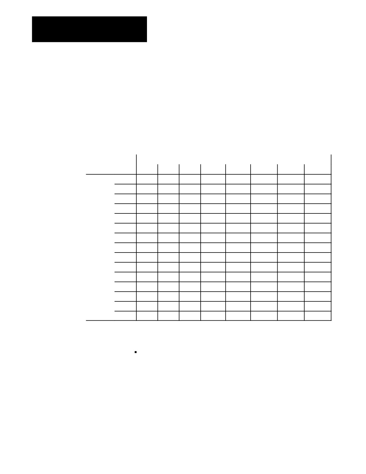
Relationships between spindle speeds and cutting diameters are shown in
Table 17.A for different surface speeds.
Table 17.A
Spindle RPM as related to cutting diameter and programmed CSS
Programmed Surface Speed, Feet/min. (meters/min.)
100(30)
200(61)
300(91)
400(122)
500(152)
1000(305)
1500(457)
2000(610)
1(25)
382
764
1146
1527
1910
3820
5730
7640
2(51)
191
382
573
764
955
1910
2865
3820
3(76)
127
254
382
509
637
1273
1910
2546
4(102)
95
191
286
382
477
955
1432
1910
5(127)
76
153
229
306
382
764
1146
1528
Cutting
6(152)
64
127
191
255
382
637
955
1273
Diameter,
8(203)
47
95
143
191
239
477
716
955
Inches
10(254)
38
76
115
153
191
382
573
764
(mm)
12(305)
32
64
95
127
159
318
477
637
14(356)
27
55
82
109
163
273
409
546
16(406)
24
48
72
95
143
239
358
477
18(457)
21
42
64
85
127
212
318
424
20(508)
19
38
57
76
115
191
286
382
25(635)
15
31
46
61
92
153
229
306
30(762)
12
25
38
51
76
127
191
255
Notes on Constant Surface Speed
Normally the system installer sets a maximum speed in AMP; however,
the programmer has the option of lowering this maximum speed if
desired. An allowable upper limit for RPM can be programmed by a
G92 followed by an S value in RPM. This upper limit is valid only for
the G96 mode and is ignored in G97 mode. The value for this upper
limit can not exceed the value set in AMP for the maximum spindle
RPM.
To enter 3500 rpm as the upper limit, program:
G92S3500;
17-6
Chapter 17
Spindles
In G96 mode, spindle speeds increase as the workpiece diameter
decreases. When the spindle speed reaches the upper limit, it is held at
this value even if the theoretical spindle speed exceeds that value. This
maximum RPM may also be affected by the maximum gear speed set
for a specific gear in AMP.
Important: The G92s command to set a new max spindle RPM in CSS
may not be programmed while CSS is active.
Important: The G92, maximum spindle RPM limit for CSS,
programmed in a block is applied as the CSS limit for the currently
active controlling spindle (selected with the G12 code). For systems
allowing multiple spindles, if the controlling spindle is changed between
the G92 and CSS activation, then the required G92 limit may not be
active for the proper spindle.
The G92 maximum spindle RPM is canceled only after power is shut
down, a control reset is performed, or when the control goes into
E-STOP. M02 or M30 cannot cancel this value. When canceled, the
system installers maximum speed becomes effective again.
Spindle speed during rapid traverse
In the G96 mode, when rapid axis feed starts, spindle speeds are
controlled in one of two ways:
The spindle speed changes as X axis moves.
or
The control calculates the spindle speed attained at the end of the move
and uses that spindle speed for the entire rapid move.
The system installer selects in AMP which spindle speed control type he
wants.
Activating and deactivating CSS mode with M-codes (M58/M59)
Use M58 or M59 to turn constant surface speed mode on or off.
When M59 is programmed, the control ignores G96 mode and the
spindle revolves at the same speed as when this M-code is executed.
When M58 is executed, the G96 mode becomes active again.
If an S-code is programmed in the same block as an M59, G96 mode is
ignored and the S-code value is registered in memory as a constant
surface speed S-code, but the spindle speed does not change with
diameter.
17-7

Chapter 17
Spindles
When programming M58, the M59 code is cancelled and the G96 mode
becomes active again. The spindle maintains the same surface speed
that was in effect prior to the execution of M59 unless an S-code was
specified in the M59 block.
CAUTION: Restoring the constant surface speed mode might
cause the spindle speed to change rapidly depending on the
cutting tool position.
Displayed spindle speed during CSS
The CRT display normally shows the current spindle speed in RPM
following the S-word. This is true during CSS also. The display shows
the actual spindle RPM, not the surface speed.
CSS R-word programming
The optional R-word lets you specify a surface footage value to be
applied at a point other than the current axis position. The R-word
defines the incremental distance from the current tool tip to the spindle
centerline. The sign of the R-word defines on which side of the spindle
centerline the tool tip is positioned.
The R-word is recognized only in a G96 block; its value is valid as long
as CSS mode is active and may only be changed when a G96 is
programmed in the block.
If you change the S-word (surface footage) while in G96 mode and if an
R-value was previously programmed in a G96 block, the R-value is not
cancelled.
Important: An R0 and no R-word do not mean the same thing. An
R-word of zero means that the spindle centerline is the tool tip position.
No R-word means to use the current position.
17-8
Chapter 17
Spindles
17.1.2
In the G97 mode, the spindle revolves at the programmed RPM regardless
of the position of the cutting tool.
RPM Spindle Speed Mode
(G97)
For example, to revolve the spindle at 500 rpm, program:
G97 S500 M03;
The G97 code is modal and remains active until it is cancelled by the G96
code.
Important: If an S-word is specified in the G97 block when you change
from G96 to G97 mode, the control uses the S-word as the new RPM
value. If no S-word is contained in the G97 block, the control uses the
current RPM of the tool as the programmed spindle RPM. The spindle
speed then remains at this constant RPM.
17.2
Use the G12 code to program the active controlling spindle for all
Controlling Spindles
programmed axes motions for features and modes requiring spindle
operation. The G12 code is modal as only one spindle can be the
(G12.1, G12.2, G12.3)
controlling spindle. All other spindles are auxiliary spindles.
G12.1 — Spindle 1 Controlling
G12.2 — Spindle 2 Controlling
G12.3 — Spindle 3 Controlling
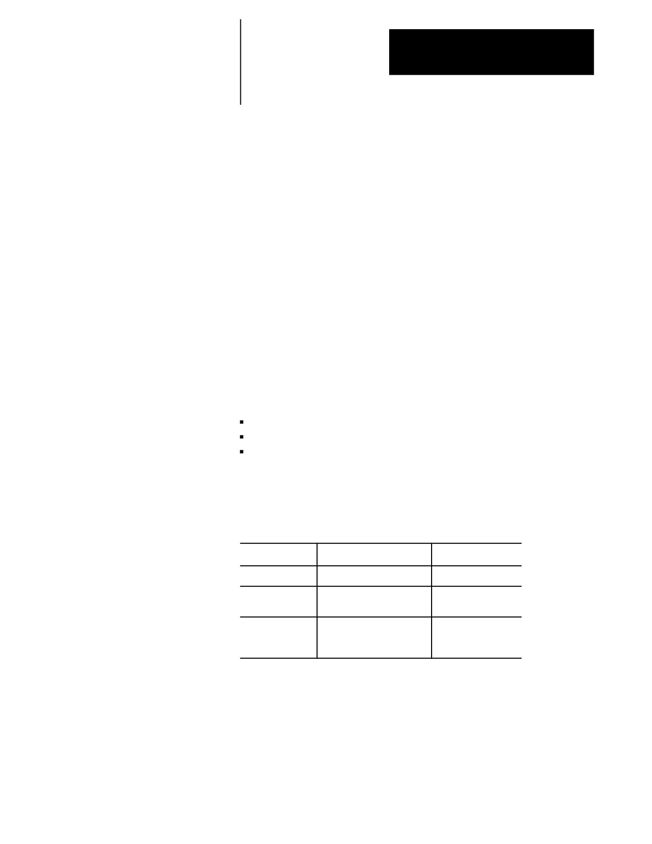
Table 17.B lists the allowed spindle capabilities.
Table 17.B
Spindle Capabilities
Control Type
Number of Spindles
Spindle Type
9/230 or 9/240
1
Primary
9/260
2
Primary
Auxiliary 2
9/290
3
Primary
Auxiliary 2
Auxiliary 3
The spindle 1, as well as spindle 2 and 3, must be configured in AMP, and
the associated spindle parameters must be set properly to provide for the
required spindle functions.
17-9

Chapter 17
Spindles
For systems with no spindle configured, simulated spindle feedback is
provided for the primary spindle. This allows all control features that
require spindle feedback, i.e., IPR feedrate, threading, CSS, to simulate the
feedback from a spindle even through the AMPed system configuration
contained no spindle. The default is 4000 count-per-rev device.
Important: On the 9/260 and 9/290 controls, if the auxiliary spindles are
programmed but have not been configured as active through AMP, these
errors are given as decode errors on any blocks that have the G12.2 or
G12.3 code:
“SPINDLE 2 NOT CONFIGURED” and/or
“SPINDLE 3 NOT CONFIGURED”
17.3
For each possible spindle configured, the control is equipped to perform a
Spindle Orientation
spindle orient operation. This operation is used to rotate the spindle to a
given angle. Typically this may be used to orient the spindle for
(M19, M19.2, M19.3)
load/unload operations, to position a chuck for automatic chuck wrench
operation, etc. This orient operation is not the same as using a spindle as
an axis for positioning. See virtual C axis, section 17.5. An orient
operation is performed separately from axis motions and cannot be
interpolated with normal axis motions.
There are two types of spindle orients available. They are:
Open-loop orient - The spindle does not use a feedback device for this
type of orient. The final destination of the spindle when performing an
open-loop orient is determined by PAL. Typically there is some form of
hardware switch used to determine the spindle is at the proper position.
When the open-loop orient is performed the spindle is turned at an
AMP-defined RPM and in an AMP-defined direction.
Closed-loop orient - The spindle must be equipped with a feedback
device. The final destination of the spindle when performing a
closed-loop orient may be determined in AMP, or entered in a program
block requesting an orient. When the closed-loop orient is performed,
the spindle is positioned at an AMP-defined RPM.
If the spindle is:
the orient will:
turning
complete in the same direction as the spindle is currently revolving.
If the spindle is turning faster than the orient speed defined in AMP, it
first slows to that orient speed before performing the orient.
not turning
be performed in whichever direction that results in the spindle
reaching the required position by using the shortest angular distance.
17-10
Chapter 17
Spindles
Important: A spindle orient is also sometimes automatically requested by
the control when performing some of the drilling cycles described in
chapter 26. This drilling cycle orient orients to either the AMP-defined
position if using a closed-loop orient type or to the position defined as the
open-loop orient position.
Important: In systems allowing multiple spindles (9/260 ad 9/290), only
one M19 code can be in a block. If two or more M19 codes appear in one
block, e.g., M19.2 M19#, this error message appears, “ONLY ONE M19
ALLOWED PER BLOCK.”
Refer to your system installer’s documentation to determine which orient
your system is equipped to perform. This manual assumes that a
closed-loop type orient is available. If an open-loop orient is used, refer to
the system installer’s documentation for details on its operation, as it is
highly PAL dependant.
Both open- and closed-loop spindle orients can be requested either by
programming the appropriate spindle orient code (M19, M19.2, M19.3) in
a program block, or by requesting one through PAL. If closed-loop orient
is requested through PAL, the orient angle is fixed at the default orient
angle preset by the system installer in AMP.
If a closed-loop orient is requested by programming the appropriate
spindle orient code (M19, M19.2, M19.3), the option exists to orient the
spindle to the AMP-defined orient position or to a position programmed
with an S parameter in the M19 block. The S parameter defines an angle
at which the spindle is positioned relative to an angle of zero that is fixed
for a specific machine. Refer to the documentation prepared by the system
installer. This S parameter always programs an absolute angular position.
The angle programmed is not affected by incremental or absolute
programming mode (if open-loop orient is being used, the value
programmed with the S parameter is ignored).
The M19 code is modal. However, each time it is necessary to orient to a
specific angle, an M19 with an S-word must be programmed.
Programming an S-word alone replaces the current modal spindle speed
used later when the M19 mode is canceled. Cancel the M19 spindle orient
by programming one of the other spindle mode M-codes.
17-11
Chapter 17
Spindles
To cancel spindle orient:
Program:
Meaning:
Spindle 1
M03
Spindle 1 clockwise
code M19
M04
Spindle 1 counterclockwise
M05
Spindle 1 stop
Spindle 2
M03.2
Spindle 2 clockwise
code M19.2
M04.2
Spindle 2 counterclockwise
M05.2
Spindle 2 stop
Spindle 3
M03.3
Spindle 3 clockwise
code M19.3
M04.3
Spindle 3 counterclockwise
M05.3
Spindle 3 stop
17.4
Use the spindle directional M-codes to program each configured spindle
Spindle Direction
program controlled spindle rotation.
(M03, M04, M05)
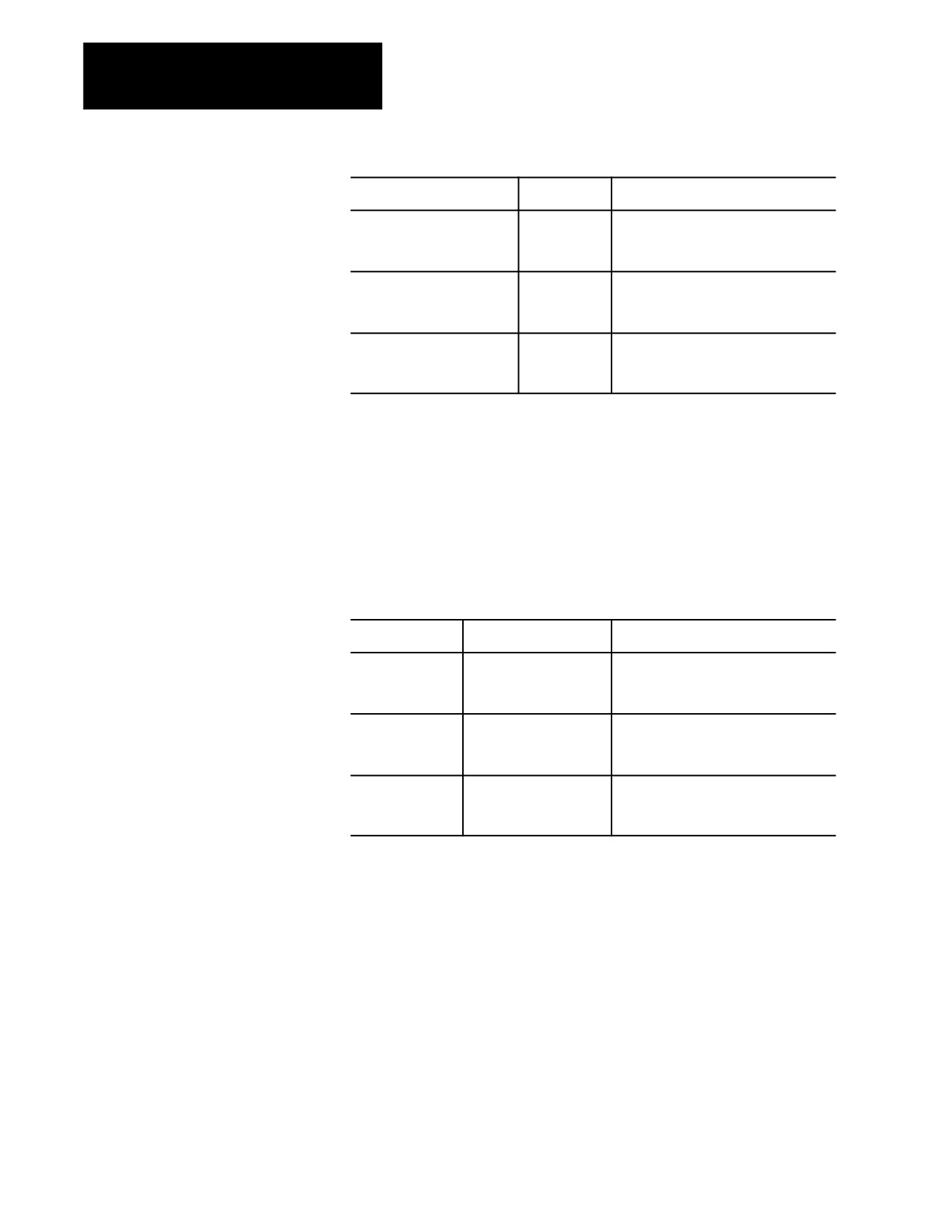
Table 17.C lists the spindle direction codes.
Table 17.C
Spindle Directional Codes
Spindle Type
Directional Code
This means:
Primary
M03
Spindle 1 clockwise
M04
Spindle 1 counterclockwise
M05
Spindle stop
Spindle 2
M03.2
Spindle 2 clockwise
M04.2
Spindle 2 counterclockwise
M05.2
Spindle 2 stop
Spindle 3
M03.3
Spindle 3 clockwise
M04.3
Spindle 3 counterclockwise
M05.3
Spindle 3 stop
Each spindle can have independent rotational control, and the rotational
speed is programmed by using the S-word. If a directional spindle code is
programmed in the same block as the S-word, then that S-word is applied
to each of the block’s associated spindles.
17-12

Chapter 17
Spindles
Example 17.1
9/290 Control with 3 Spindles Configured in AMP
N0001 M05
Spindle 1 stop
N0002 M05.2 M05.3
Spindles 2 & 3 stop
N0003 M03 M04.2 S150
Spindle 1 clockwise 150 rpm
Spindle 2 counterclockwise 150 rpm
N0004 M03.2 M03.3 S10
Spindle 2 clockwise 10 rpm
Spindle 3 counterclockwise 10 rpm
Important: On the 9/260 and 9/290 controls, if the auxiliary spindle
directional M-codes are programmed but the auxiliary spindles have not
been configured as active through AMP, these errors are given as decode
errors on any blocks that have directional M-codes of the associated
spindle programmed:
“SPINDLE 2 NOT CONFIGURED” and/or
“SPINDLE 3 NOT CONFIGURED”
17.5
The Virtual C Axis feature allows the control to interpolate a rotary axis
(typically the lathe spindle) with the machine axes. This allows for
Virtual C Axis
circular machining along the circumference or across the face of a
workpiece while it is rotated, as shown in Figure 17.3 and Figure 17.5.
If the spindle is used as the virtual C axis, it may require that an alternate
motor and/or higher precision feedback device be used. The alternate
motor would be configured as a closed-loop rotary axis. Refer to the
documentation provided by your system installer.
This description assumes that the lathe spindle has been configured in
AMP to be used as the virtual C axis.
We refer to this axis:
As:
the virtual C axis
C
the axis along the spindle center line (also called the park axis)
Z
the axis perpendicular to the spindle center line (also called the feed axis)
X
Refer to the literature provided by your system installer for the axis names
used by your machine.
17-13
Chapter 17
Spindles
To function as a virtual C axis, the lathe spindle must have a precision
encoder that provides position data to the control. There can be only one
encoder marker per revolution of the spindle. When the virtual C axis
feature is activated, the control switches spindle operation from an
open-loop spindle to a closed-loop virtual C positioning axis.
CAUTION: It is the responsibility of the operator (or the
control’s PAL program) to change spindle gears as required to
attain one revolution of the encoder per revolution of the
spindle prior to execution of the G16.1.
While the virtual C axis feature is active, programmed spindle commands
(M03, M04, M05, or M19) do not affect the operation of the lathe spindle.
It is up to the control’s PAL program to interpret these part program
commands and take appropriate action, such as directing them to a “live
tool” spindle.
Typically a live tool powered by an external drive and mounted on the X
and Z axes is used to machine contours on the workpiece during virtual C
operation. Operation of the live tool is controlled through PAL.
The control uses the $VIRTC PAL flag to indicate to PAL that the virtual C
axis feature is active. Refer to the documentation prepared by your system
installer for details.
Virtual C Programming Restrictions
When the virtual C axis feature is enabled, these programming restrictions
apply:
The control must be in feedrate per minute mode (G94), not feedrate per
revolution mode, before beginning virtual C programming
Work coordinate system offsets (G52, G54--G59, and G92) for the park
and feed axes (Z and X) are temporarily cancelled when in G16.1 mode.
Offsets for other axes are not affected
Tool offsets and cutter compensation/TTRC offsets are allowed during
Virtual C programming
Cutter compensation ignores the tool orientation and treats the
programmed tool as a mill tool (orientation 0)
Activation of offsets through PAL is disabled
Jog on the fly is disabled
Integrand circle/arc programming is not permitted during G02/G03
blocks. Only direct radius (R) programming is allowed
17-14
Chapter 17
Spindles
Only the primary spindle (selected with G12.1) can be used in coordination
with virtual C. On systems allowing auxiliary spindles, if the auxiliary
spindle is the controlling spindle when virtual C is activated, this error
message appears, “ILLEGAL CODE DURING VIRTUAL C.”
17.5.1
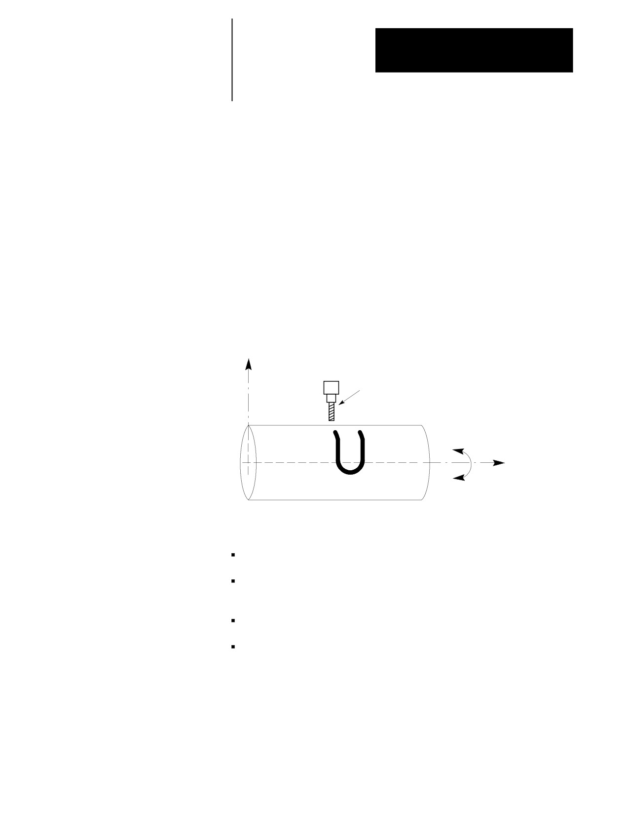
Cylindrical interpolation coordinates the motion of the virtual C axis with
that of the linear machine axes to machine contours on the side of a
Virtual C Axis,
cylindrical workpiece as shown in Figure 17.3. Virtual C cylindrical
Cylindrical Interpolation
interpolation mode is turned on using a G16.1 block and turned off with a
G15 block (or a G16.2 block requesting end face milling). A G15 block
can not contain any axis words.
Figure 17.3
Virtual C Axis Cylindrical Interpolation
X
Lathe Live Tool
C
Z
The following are not allowed during cylindrical interpolation:
automatic motion to and from home G27, G28, G29, or G30
work coordinate changes and shifts G53, G54-G59, G59.1, G59.2,
G59.3, G50/G92, G52, G92.1
all turning and threading cycles
all drilling, tapping, and boring cycles
Cylindrical Interpolation Block Format
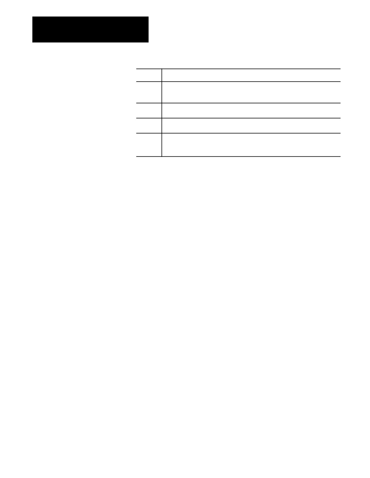
The format for the G16.1 block (virtual C axis cylindrical interpolation) is:
G16.1 R__ F__; C__ Z__;
17-15
Chapter 17
Spindles
Where:
Is:
R
the radius at which the feed axis (typically the X axis) is positioned at the start of
cylindrical interpolation. Can be used to alter the feed axis depth if programmed in a
G16.1 block during cylindrical interpolation.
C
the angular coordinate (if in G90 absolute mode) or the angular distance (if in G91
incremental mode) to which the virtual C axis is to move.
Z
the coordinate (if in G90 absolute mode) or the linear distance (if in G91 incremental
mode) to which the Z axis is to move.
F
the feedrate to be used by the feed axis to position to radius R, and used by the Z axis
when commanded to move while G16.1 is active.
It also controls the virtual C axis speed as though it were a rotary axis. See chapter 18.
These parameters and their application are described in detail in the
paragraphs that follow:
The valued entered for the R parameter should place the tool at the radius
of the desired cutting depth into the part.
Important: R must be programmed in the initial G16.1 block. If R is not
programmed in the initial G16.1 block, the error message “CYLINDER
RADIUS IS ZERO” appears. At power turn-on, program-end (M02, M30,
or M99) or control reset, the virtual C axis feature is turned off and the R
value is set to zero. It must then be re-entered in the next G16.1 block.
The radius specified by the R parameter is modal and does not need to be
included in subsequent cylindrical interpolation blocks. Programming a
G16.1 block with a different R value modifies the feed depth to the new
radius. Feed depths cannot be changed using the X parameter when G16.1
is active. Programming an X generates the error message “FEED AXIS
MOTION NOT ALLOWED.”
Figure 17.3 illustrates the tool position if the AMP parameter Feed Axis
Park Location is selected as “Farthest from Machine Zero.” If “Nearest
to Machine Zero” were selected, then the tool would be positioned for
cutting into the part from the negative side of the X axis. Refer to the
information provided by your system installer.
A C or Z axis position may be programmed with the R parameter in the
initial G16.1 block. However, once G16.1 mode is established, only the Z
parameter can be programmed in the same block as the R parameter.
When it is, the Z axis motion executes first followed by feed axis motion to
radius R.
If a C axis position is programmed, the C axis rotates to the specified
angle. If the C and Z axes are programmed together in the same block,
then a vector motion results around the circumference of the part.
17-16
Chapter 17
Spindles
If G02 or G03 circular interpolation is made active while in G16.1
cylindrical interpolation mode, a circular cut can be made around the
circumference of the part (such as the shape cut in Figure 17.3). This is
accomplished by programming the C and Z axis endpoints along with the
desired circle radius R as described in chapter 14. The R parameter now
defines the radius of the circular path to be cut, not the feed axis position.
Important: When programming circular interpolation in G16.1 mode,
only radius programming (using R) may be used. Integrand programming
(using I, K) is not allowed and generates the error message “CIRCLE
PROGRAMMING ERROR.” See chapter 14.
Important: C axis motion is programmed as an angular value. When
programming circular interpolation in G16.1 mode, this angular value has
to be derived from a C axis arc length (based on the cutting radius). Refer
to Example 17.2.
To perform G02/G03 circular interpolation while in G16.1 mode, the linear
axis (Z) and the virtual C axis (C) must move to the endpoint of the arc of
radius R made on the side of the cylinder.
In incremental mode (G91) the C axis arc length along with the
programmed Z move length, must position the C and Z axes at a legal
endpoint for the arc radius defined by the R value in the G02/G03 block.
In absolute mode (G90) the coordinate defined by the C axis arc along with
the coordinate programmed for the Z axis, must position the C and Z axes
at a legal endpoint for the arc radius defined by the R value in the
G02/G03 block.
When cylindrical interpolation is activated, the circle plane is set to ZC.
The C and Z axes become the two axes of the circle plane and remain so,
as long as the G16.1 mode is active. If the active plane is changed, the
change does not become effective until the G16.1 mode is cancelled, and is
superceded if the G16.1 plane is reactivated.
Cylindrical Interpolation Operation
When virtual C axis cylindrical interpolation is activated, the control
terminates any spindle operations and defines the current spindle position
as zero degrees. If the AMP parameter Automatic Home on Virtual C
Entry is set to “YES,” a homing operation was performed prior to this.
The control then switches spindle operation from an open-loop spindle to a
closed-loop positioning axis.
Important: If orientation of the part is important, or if you expect to leave
G16.1 mode and then return and continue work on a specific area of the
part, the primary spindle should be homed each time you enter the G16.1
17-17
Chapter 17
Spindles
mode. If the AMP parameter Automatic Home on Virtual C Entry is
set to “NO” (refer to the documentation provided by your system installer),
you need to home the virtual C axis, typically by programming a M19S0.
The control positions the tool on the cylindrical work surface with two
distinct moves. In the first move, all programmed axis moves in the initial
G16.1 block (including the C axis) are executed. This move takes place at
the rapid feedrate for the axes.
In the second move, the feed axis (X) is moved at the active cutting
feedrate to the radius specified by R.
The blocks following the G16.1 block determine the contour to be
machined on the side of the cylindrical workpiece. The moves of the
virtual C axis and the machine axes are interpolated to produce the
programmed contours.
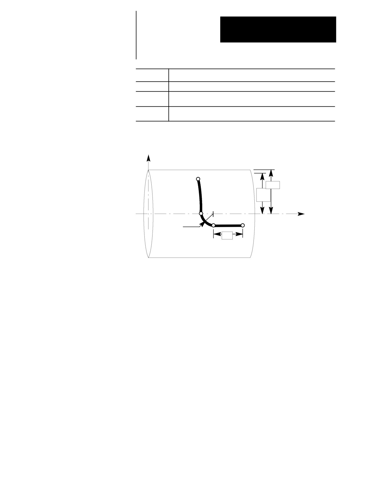
The following example makes a circumferential cut, followed by a 90
degree arc, followed by a linear cut, all made into the side of a cylindrical
workpiece. The C axis angle in the G03 block of this program was derived
from the equation that follows this example. Figure 17.4 illustrates the
results.
Example 17.2
Virtual C Axis, Cylindrical Interpolation
N1
G91 M05;
N2
G16.1;
N3
C10. Z-40.;
N4
C60.;
N5
G03 Z8. C18.335 R8.;
N6
Z20.;
N7
G16.1 R30.;
N8
G15;
The angle for the C move in the G03 block above was determined by using
this equation, with L = 8 and R = 25.
360
( L )
q
=
-------------
2 p( R )
17-18
Chapter 17
Spindles
Where :
Is :
q
The angle to be programmed for the virtual C axis.
L
The length of the arc along the circumference of the cylinder, as required to
define a legal endpoint for the arc programmed in the G02/G03 block.
R
The radius at which the feed axis is positioned. This is the active R value
programmed in the initial G16.1 block, not the R radius for the G02/G03 block.
Figure 17.4
Results of Cylindrical Interpolation, Example 17.2
X
N2
28
25
(R)
N3
Z
Arc radius
N4
N5
of 8
20
17-19
Chapter 17
Spindles
17.5.2
End face milling coordinates the motion of the virtual C axis with that of
the linear machine axes to machine contours on the end face of a
Virtual C Axis,
workpiece as shown in Figure 17.5. Virtual C axis end face milling is
End Face Milling
turned on using a G16.2 block and turned off with a G15 block (or a G16.1
block requesting cylindrical interpolation). A G15 block can not contain
any axis words.
Figure 17.5
Virtual C Axis End Face Milling
Y (simulated)
C
N4
N3
N2
Lathe Live Tool
N5
N6
The following are not allowed during end face milling:
Automatic motion to and from home G27, G28, G29, or G30
Work coordinate changes and shifts G53, G54-G59, G59.1, G59.2,
G59.3, G50/G92, G52, G92.1
All Turning and Threading cycles
All Drilling, Tapping, and Boring cycles
For ease of programming and to help the programmer visualize contours, a
simulated axis (end face milling axis) perpendicular to the X axis is
utilized with this feature. This axis name, its incremental axis name (if
Lathe Type A), and its integrand name are defined in AMP. This
description assumes that those names are Y, V, and J respectively. Refer to
the literature provided by your system installer for specific information.
17-20

Chapter 17
Spindles
End Face Milling Block Format
The block used to activate virtual C axis end face milling has this format:
G16.2 X__ Y__ Z__ R__ F__
Where :
Is :
X
The coordinate (if in G90 absolute mode) or the linear distance (if in G91
incremental mode) to which the X axis is to move. Be aware that this value is
affected by diameter (G08) or radius (G07) programming mode.
Y
The coordinate (if in G90 absolute mode) or the linear distance (if in G91
incremental mode) to which the simulated Y axis is to move.
Z
The coordinate (if in G90 absolute mode) or the linear distance (if in G91
incremental mode) to which the Z axis is to move. This axis determines depth of
cut in End Face Milling.
R
The radius of the arc to be cut in the face of the part. This parameter can be
used only if G02 or G03 circular interpolation has been activated, and must be
programmed with the correct X and Y coordinates. See chapter 14.
F
The feedrate to be used by the X, Y, and Z axes when commanded to move while
G16.2 is active.
These parameters and their application are described in detail in the
paragraphs that follow:
Any axis motions except for C axis motions can be programmed in the
G16.2 block. The control generates C axis motion in response to
programmed requests for simulated Y axis motion. This allows the
programmer to enter his contour moves as though he were working with an
XY plane, with cutting depth controlled by the Z axis.
If G02 or G03 circular interpolation is made active while in G16.2 end face
milling mode, circular cuts can be made in the face of the part (for
example, the corners could be rounded in the contour illustrated in
Figure 17.5). This is accomplished by programming the X and Y axis
endpoints along with the desired circle radius R as described in chapter 14.
The R parameter used here defines the radius of the circular path to be cut.
Important: When programming circular interpolation in G16.2 mode,
only radius programming (using R) may be used. Integrand programming
(using I, J) is not allowed and generates the error message “CIRCLE
PROGRAMMING ERROR.”
Important: When programming circular interpolation in incremental
mode (G91), the programmed X move length along with the programmed
Y move length, must position the X and Y axes at a legal endpoint for the
circular radius defined by the R value in the G02/G03 block. In absolute
mode (G90) the coordinate programmed for the X axis along with the
coordinate programmed for the Y axis, must position the X and Y axes at
a legal endpoint for the circular radius defined by the R value in the
G02/G03 block.
17-21
Chapter 17
Spindles
When end face milling is activated, the circle plane is set to XY. The X
axis becomes the primary axis of the circle plane and remains so, as long
as the G16.2 mode is active. If the active plane is changed, the change
does not become effective until the G16.2 mode is cancelled, and is
superseded if the G16.2 plane is reactivated.
End Face Milling Operation
When virtual C axis end face milling is activated, the control terminates
any primary spindle operations and defines the current primary spindle
position as zero degrees. If the AMP parameter Automatic Home on
Virtual C Entry is set to “YES,” a homing operation was performed prior
to this. The control then switches primary spindle operation from an
open-loop spindle to a closed-loop positioning axis.
Important: If orientation of the part is important, or if you expect to leave
G16.2 mode and then return and continue work on a specific area of the
part, the primary spindle should be homed each time you enter the G16.2
mode. If the AMP parameter Automatic Home on Virtual C Entry is
set to “NO” (refer to the documentation provided by your system installer),
you need to home the virtual C axis, typically by programming a M19S0.
The blocks following the G16.2 block determine the contour to be
machined on the end face of the cylindrical workpiece. The moves of the
virtual C axis and the machine axes are interpolated to provide the
programmed contours on the workpiece face.
Example 17.3 generates a square cut in the face of a part similar to that
show in Figure 17.5.
Example 17.3
Virtual C Axis, End Face Milling
N1
G91 M05 X-20.;
N2
G16.2 Z-5.;
N3
Y10.;
N4
X-20.;
N5
Y-20.;
N6
X20.;
N7
Y-10.;
N8
Z5.;
N9
G15;
17-22