9/Series CNC Lathe. Operation and Programming Manual - page 12
Chapter 12
Overtravels and Programmable Zones
12.2
The coordinate values of the points defining the software overtravels are
set in AMP by your system installer. This overtravel can only be disabled
Software Overtravels
by your system installer in AMP. If your system installer has enabled the
software overtravels, the control is not allowed to exit the area defined by
the software overtravels.
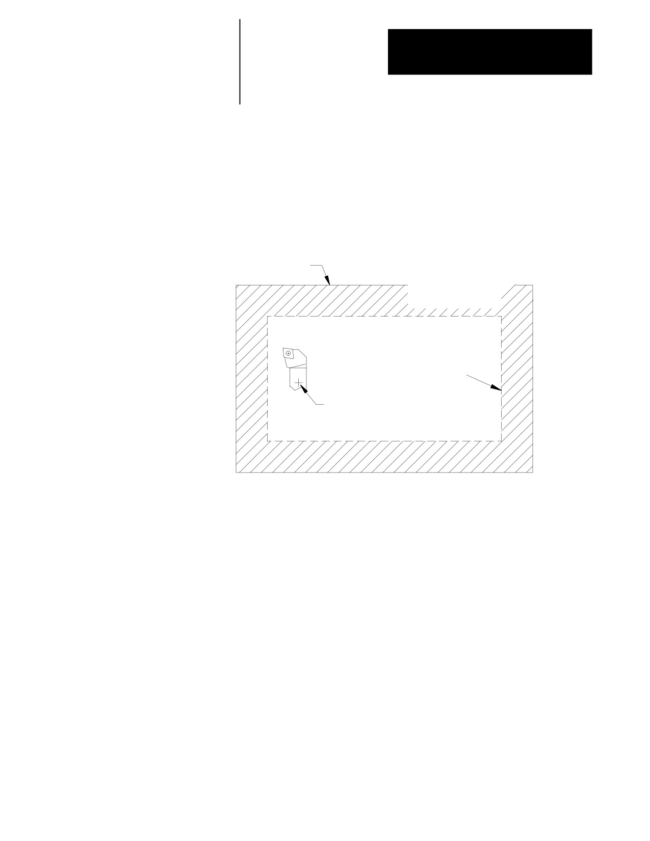
Figure 12.2
Software Overtravels Established in AMP
Hardware
overtravel
Entry into this
area is prohibited by
the software overtravel
Cutting
tool
Software
overtravel
Absolute position is prohibited
from entering the software
overtravel (no offsets considered)
Your system installer selects values that represent a maximum and a
minimum value in the form of coordinate values for each axis. These
coordinate values define points on the machine coordinate system. The
axes are not allowed to move past the coordinate value representing the
maximum and minimum value on each axis. This limited range of motion
is referred to as the software overtravels.
12-3
Chapter 12
Overtravels and Programmable Zones
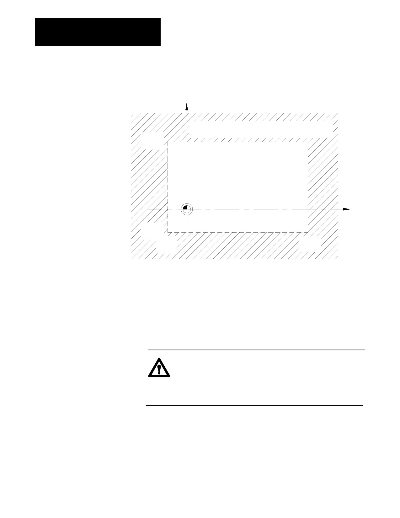
Figure 12.3
Area Defining Software Overtravel
X
Software overtravel area as defined in AMP by minimum and
maximum axis values
Max X
value
Machine
coordinate
zero
Z
Min X
value
Max Z
Min Z
value
value
Typically the software overtravels are located within the hardware
overtravels (maximum axis travel defined by the limit switches on each
axis), and they are used to keep the axes within the range your system
installer determines is usable for that particular machine’s application.
The area defined by the software overtravels becomes effective after
completion of the initial homing operation at power up. For details on how
the control reacts to a entry into an overtravel area, see page 12-13.
CAUTION: The area defined by a software overtravel does not
take in to account any offsets. This allows the actual tool to
enter the restricted area without the axes absolute position
entering it. Make sure this is considered when the software
overtravel is established.
12-4
Chapter 12
Overtravels and Programmable Zones
12.3
Programmable zone 2 defines an area which the tool cannot enter.
Generally, zones are used to protect some vital area of the machine or part
Programmable Zone 2
located within the software overtravels.
Important: Programmable zones are defined using coordinates in the
machine coordinate system. They are not affected by any changes in the
work coordinate system, including external offsets.
WARNING: Programmable zones only protect the tool tip
from entering the zone (as determined with the currently active
tool length offset). They do not protect other moving members
from collision with objects in the programmable zone’s
boundary.
Values for programmable zone 2 are entered in the programmable zone
tables as described on page NO TAG. These values represent a maximum
and a minimum value in the form of machine coordinate values for each
axis. The area defined by these points establishes the boundaries for
programmable zone 2.
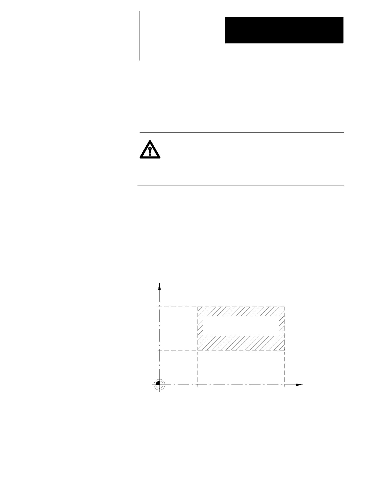
Figure 12.4
Area Defining Programmable Zone 2
X
Max X
value
Programmable Zone 2
as defined by minimum
and maximum axis values
Min X
value
Machine
coordinate
zero
Z
Min Z
Max Z
value
value
Important: When changing a tool offset or activating a programmable
zone 2, the current tool tip location must be outside of the area defined by
programmable zone 2.
12-5
Chapter 12
Overtravels and Programmable Zones
Programming
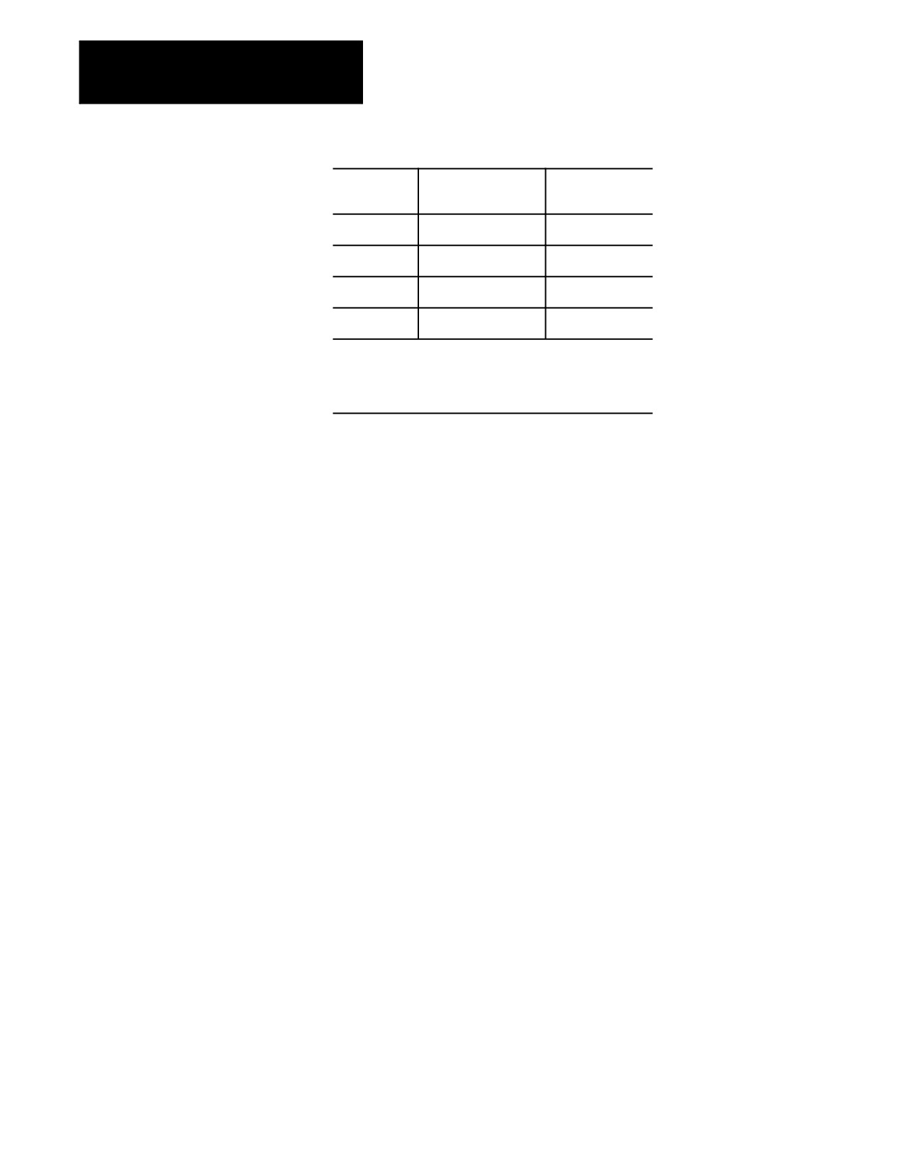
turns Zone 2:
turns Zone 3:
this G-code:
G22
On
On
G22.1
Off
On
G23
Off
Off
G23.1
No Change*
Off
* A G23.1 turns on programmable zone 2 ifitis the default
power up condition configured in AMP (also activated at a
control reset). G23.1 does not turn on programmable zone 2
when it is activated in a part program.
G23 is normally automatically made active at power up, though this is
ultimately determined by the system installer in AMP. Your system
installer also determines in AMP if an M02 or M30, control reset, or
E-STOP reset cancels programmable zones that you have turned on or off
while executing your program.
Important: If you program a G22, any axis words included in the block
are stored as the coordinates for programmable zone 3. See page 12-7 .
If you attempt to program some other command in a G22 or G23 block, for
example:
G22 G01 X12.;
the control issues the error message:
“UNUSABLE WORDS IN ZONE BLOCK”
12-6
Chapter 12
Overtravels and Programmable Zones
Figure 12.5
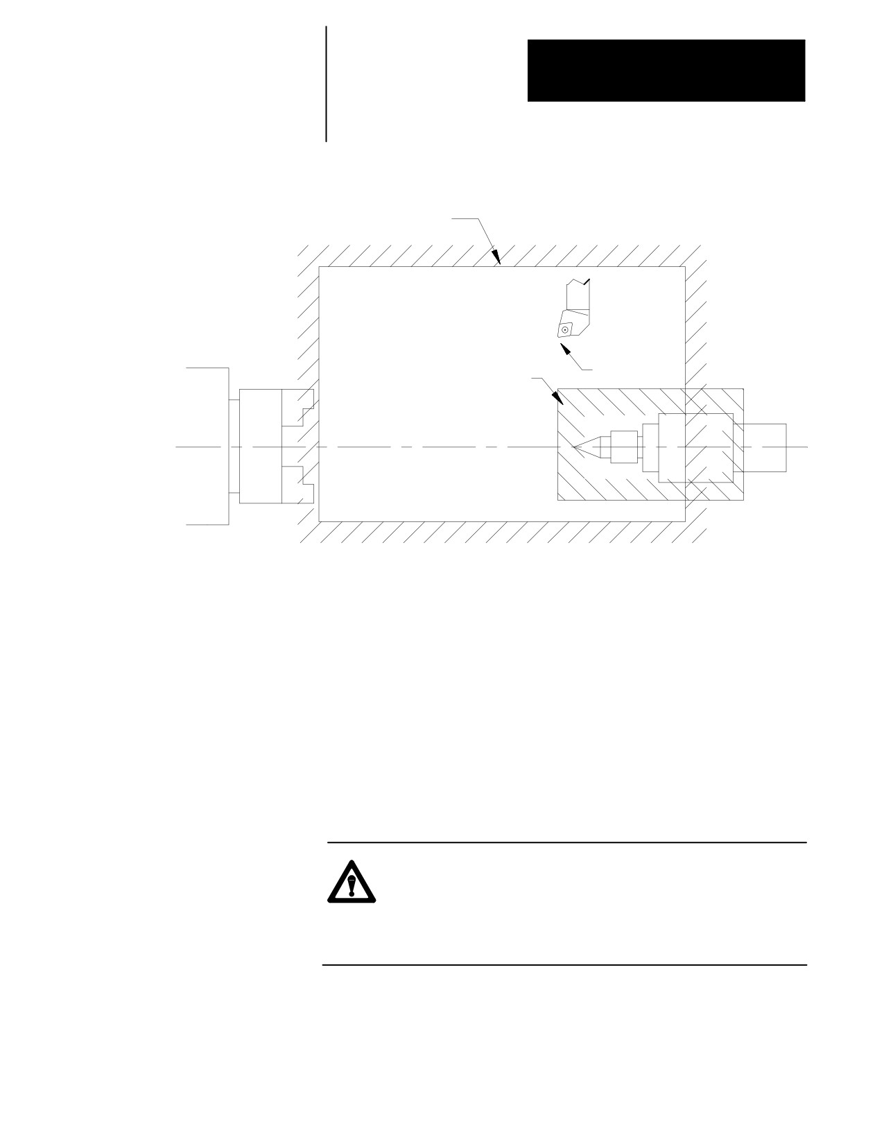
Programmable Zone 2
Software overtravel
Tool tip can not
Programmable
enter zone 2
Zone 2
For details on how the control reacts to entry into a prohibited area, see
page 12-13.
12.4
Programmable zone 3 can define an area which the tool cannot enter or
an area the tool cannot exit. The current tool location determines when
Programmable Zone 3
programmable zone 3 is made active. Generally, zones are used to protect
some vital area of the machine or part located within the software
overtravels.
Important: Programmable zones are defined using coordinates in the
machine coordinate system. They are not affected by any changes in the
work coordinate system, including external offsets.
WARNING: Programmable zones only protect the tool tip
from entering the zone (as determined with the currently active
tool length offset). They do not protect other moving members
from collision with objects in the programmable zone’s
boundary.
12-7
Chapter 12
Overtravels and Programmable Zones
Values for programmable zone 3 are entered either in the programmable
zone table (described on page NO TAG) or through a G22 program block.
A maximum and a minimum coordinate value (in the machine coordinate
system) are assigned for each axis. The resulting coordinates define the
boundaries for programmable zone 3.
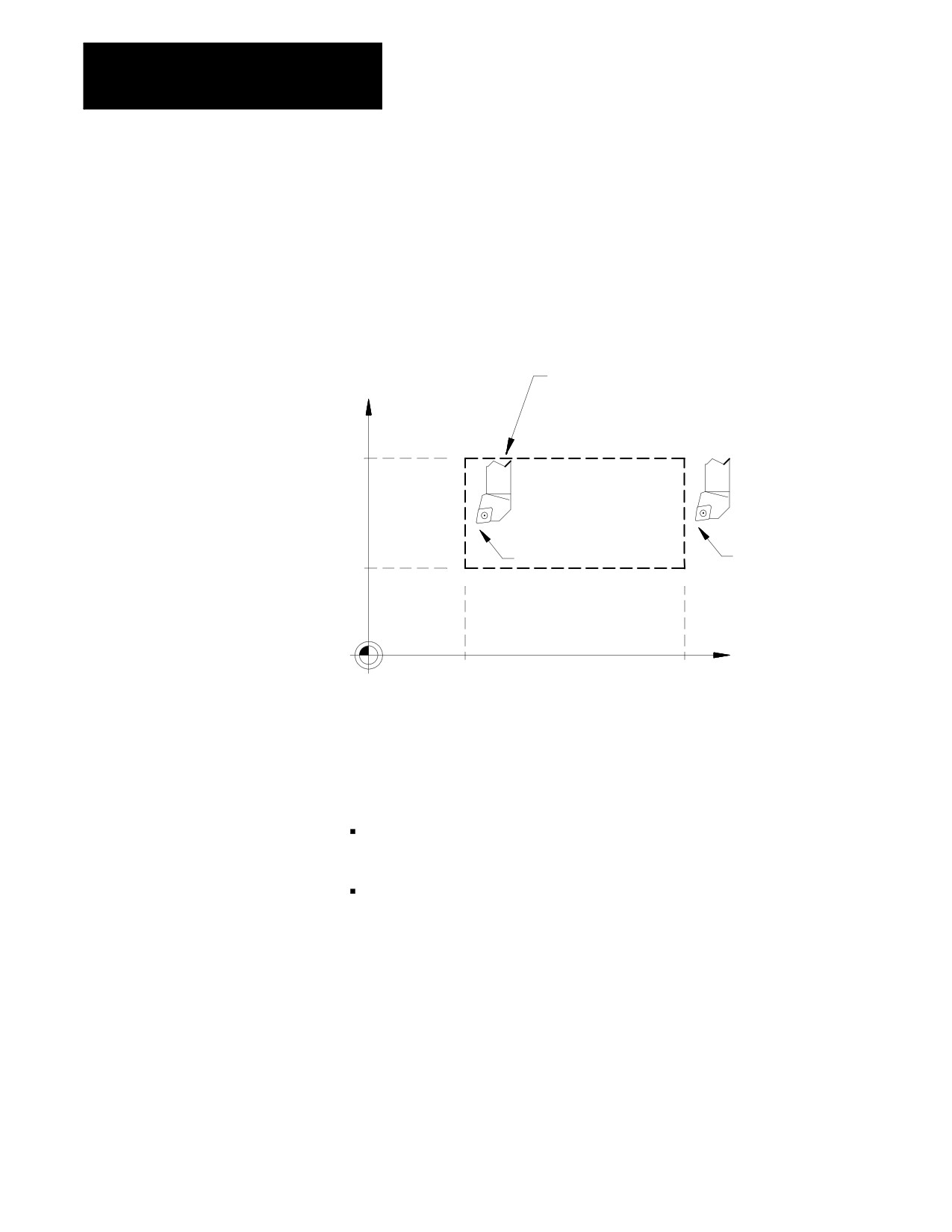
Figure 12.6
Area Defining Programmable Zone 3
Inside or outside border of
X
Programmable Zone 3
as defined by minimum
and maximum axis values
Max X
value
Tool tip can not
Tool tip can not enter if
exit if zone is activated
zone is activated while
while tool is inside zone.
tool is outside zone.
Min X
value
Machine
coordinate
zero
Z
Min Z
Max Z
value
value
Unlike the software overtravels and programmable zone 2, programmable
zone 3 can define either an area that the cutting tool can not exit or an area
that the cutting tool can not enter. This is determined by the current tool
location when programmable zone 3 is made active.
The software overtravels: define an area that the cutting tool may not
exit if the tool is currently inside the zone when the zone is activated.
Programmable Zone 3: defines an area that the cutting tool cannot enter
if the tool is outside the zone when activated or: defines an area that the
cutting tool cannot exit if the tool is inside the zone when activated.
12-8
Chapter 12
Overtravels and Programmable Zones
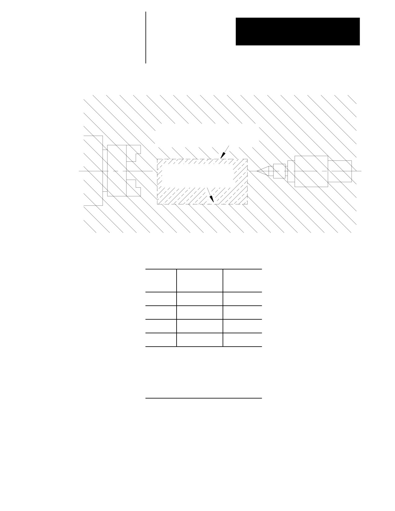
Figure 12.7
Programmable Zone 3
This area becomes Programmable
Zone 3 if the zone is enabled
when tool is inside of this area
Programmable Zone 3
if enabled when tool
is outside of this area
Programmable zone 3 becomes active when either the G22 or G22.1 code
is executed. It is made inactive when the G23 or G23.1 code is executed.
Program
To turn on
To turn off
G-code:
these zones:
these zones:
G22
2 and 3
not applicable
G22.1
3
2
G23
not applicable
2 and 3
G23.1
2*
3
* A G23.1 only turns on programmable zone 2 ifitis
activated via a control reset or power up condition.
G23.1 does not turn on programmable zone 2 if it is
programmed. To turn on programmable zone 2 and
turn off programmable zone 3, first program a G22
followed by a G23.1 to turn off programmable zone
3. Programming G23.1 has no affect on zone 2.
G22.1 and G23.1 are modal (G22.1 cancels G23.1, and G23.1 cancels
G22.1).
Important: G22.1, G23, and G23.1 must be programmed in blocks
without other commands. If you program a G22, any axis words included
in the block are stored as the coordinates for programmable zone 3.
12-9
Chapter 12
Overtravels and Programmable Zones
If you program other commands other than a G-code in the same modal
group in a G22, G22.1, G23, or G23.1 block, this error message appears:
“UNNECESSARY WORDS IN ZONE BLOCK”
Programming zone 3 values (3 or less axes)
You can reassign values for the parameters that establish programmable
zone 3 by programming axis words in a G22 program block. Two methods
are available. This section discusses programming values for zone 3 when
3 or less axes have been configured on the system (this does not include
any spindle).
Define values for programmable zone 3 using the G22 command followed
by axis words in the following format:
G22 X__ Z__ U__ I__ K__ J__;
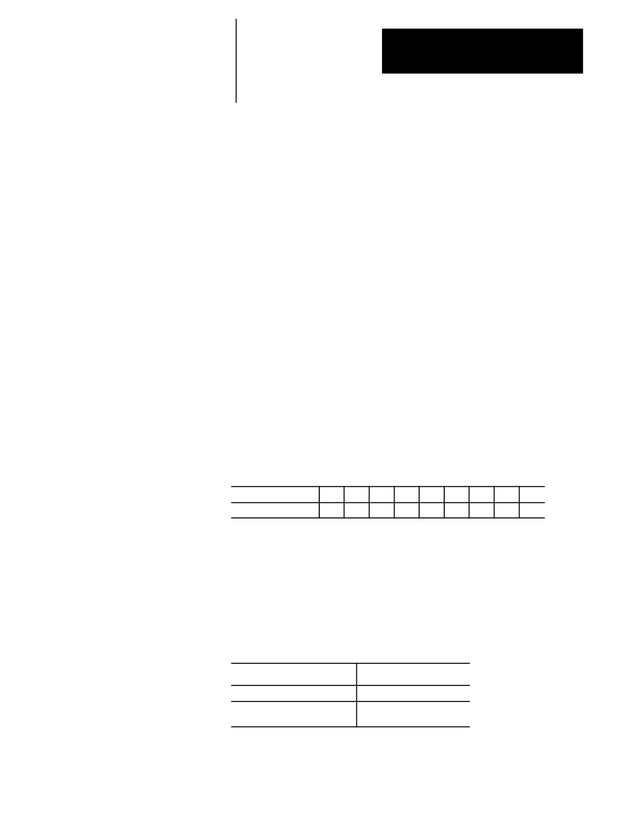
Where:
Defines:s
Absolute axis words
maximum zone limits
(normally X, Z, and U)
Integrand words
minimum zone limits
(normally I, K, and J)
These axis words can vary. Refer to your system installer’s
documentation. The following example assumes a three axis lathe
configuration. Absolute axis names are X, Z, and U. Integrands for these
axis words are I, K, and J respectively.
This block:
Results in:
G22 X10 I--10 Z14 K--14 U1 J--1;
upper and lower zone 3 limits for X, Z, and U axes
are changed. Zones 2 and 3 are both activated,
G22 X10 Z10 U20;
upper zone 3 limits are changed for X, Z, and U
axes. Zones 2 and 3 are both activated.
G22 I--10 Z10 K--5 J--3;
lower zone 3 limits for X and U axes are changed.
Both upper and lower limits for Z axis zone 3 are
changed. Zones 2 and 3 are both activated.
G22 K--10;
lower zone 3 limit for Z axis is changed. Zones 2
and 3 are both activate.
The zone values entered in a G22 block always reference coordinate values
in the machine coordinate system.
12-10
Chapter 12
Overtravels and Programmable Zones
If a value for a maximum axis parameter is less than the value set for an
axis current minimum parameter, or if a value for a minimum axis
parameter is set greater than the value set for an axis current maximum
value, the control displays the message:
“INVALID VALUE (MAX < MIN) FOR ZONE 3 AXIS (X)”
This message displays the name of the axis that has been set incorrectly. It
does not indicate if it is the minimum or maximum value that is incorrect.
If the same integrand word is assigned in AMP by the system installer to
more than one axis, that integrand word will set the lower zone 3 limit for
all axes with that integrand.
Programming zone 3 values (4 or more axes)
You can reassign values for the parameters that establish programmable
zone 3 by programming axis words in a G22 program block. Two methods
are available. This section discusses programming values for zone 3 when
4 or more axes have been configured on the system (this does not include
any spindle).
This method differs from the three axis method in that the same integrands
can be used again for different axes (necessary since the control only
supports three integrand words). Assume the following AMP
configuration:
Absolute Axis name
X
Y
Z
U
V
W
A
B
C
Axis Integrand
I
J
K
I
J
K
I
J
K
These axis words can vary. Refer to your system installer’s
documentation.
Define values for programmable zone 3 using the G22 command followed
by axis words in the following format:
G22 X__ Y__ Z__ I__ J__ K__;
G22 U__ V__ W__ I__ J__ K__;
G22 A__ B__ C__ I__ J__ K__;
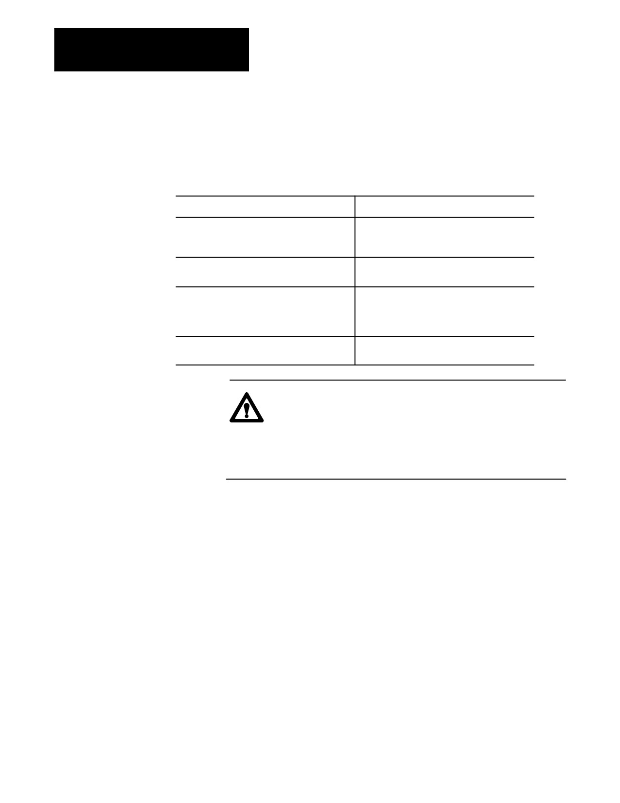
Where:
Defines:
Absolute axis words
maximum zone limits
Integrand words
minimum zone limits
(normally I, J, and K)
12-11
Chapter 12
Overtravels and Programmable Zones
Using this method, the same integrand word assigned in AMP to more than
one axis correspond only to the absolute axis words programmed in the
G22 block. Integrand words cannot be programmed alone (without a
absolute axis word in the G22 block). The following example assumes a
machine with axes configured as shown above.
These blocks:
Results in:
G22 X10 I--10 Y14 J--14 Z1 K--1;
upper and lower zone 3 limits for all 9 axes are
G22 U5 I--5 V13 J--2 W11 K10;
changed. Zones 2 and 3 are both activated when
G22 A3 I2 B7 J--7 C12 K11;
the first block in this series of blocks is executed.
G22 X1 Y2 Z3 U4 V5 W6 A7 B8 C9;
upper zone 3 limits are changed for all 9 axes.
Zones 2 and 3 are both activated.
G22 X1 Y2 Z3 U4 V5 W6 A7 B8 C9 I--1 J--2 K--3;
upper and lower zone 3 limits for all 9 axes are
changed. (I sets lower for X, U, and A: J sets
lower for Y, V, and B: K sets lower limits for Z, W,
and C). Zones 2 and 3 are both activate.
G22 K--10;
error is generated. Current status of zones
remains in current state (on or off).
WARNING: When using multiple blocks to set the zone 3
limits, keep in mind zone 3 is activated after the first G22 block.
This will result in zone 3 being activated before you have
completed changes to the zone 3 values. This can cause the
control to miss-interpret zone 3 as an internal or external zone,
depending on the tool location at the time of the zone activation.
The zone values entered in a G22 block always reference coordinate values
in the machine coordinate system.
If a value for a maximum axis parameter is less than the value set for an
axis current minimum parameter, or if a value for a minimum axis
parameter is set greater than the value set for an axis current maximum
value, the control displays the message:
“INVALID VALUE (MAX < MIN) FOR ZONE 3 AXIS (X)”
This message displays the name of the axis that has been set incorrectly. It
does not indicate if it is the minimum or maximum value that is incorrect.
12-12
Chapter 12
Overtravels and Programmable Zones
12.5
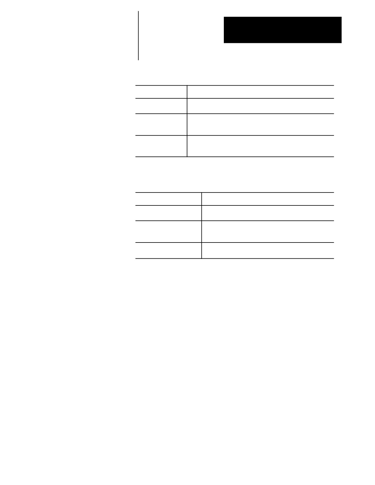
Tool motion stops during overtravel conditions that occur from 3 causes:
Resetting Overtravels
Cause:
Description:
Hardware overtravel
the axes reach a travel limit, usually set by a limit switch or sensor
mounted on the axis. Hardware overtravels are always active.
Software overtravel
commands cause the axis to pass a software travel limit. Software
overtravels are active only after the axis has been homed provided the
feature has been activated in AMP by the system installer.
Programmable zone
The tool reached a travel limit established by independent
overtravel
programmable areas. Programmable Zones are activated through
programming the appropriate G-code.
In all cases, the control issues an error message.When an overtravel
condition occurs, all axis motion stops, the control goes into cycle stop and
one of the these error messages appears.
Error Message:
Description:
HARDWARE OVERTRAVEL
indicates that the specified axis has tripped either the + or -
(-) BY AXIS (X)
hardware limit switch mounted on the machine.
SOFTWARE OVERTRAVEL
indicates that the specified axis has entered the overtravel
(+) BY AXIS (X)
area defined by the software overtravel limits in either a
positive or negative direction.
VIOLATION OF ZONE (2) BY
indicates that a tool has reached the specified axis overtravel
AXIS (X)
area defined by either programmable zone 2 or 3.
When an overtravel of any type occurs, axes cannot move in the same
direction as the feed causing the overtravel. Only axis motion in the
reverse direction is possible.
How a hardware overtravel condition is reset depends on the E-Stop circuit
design and the way PAL was programmed by your system installer.
To reset a software or programmable zone overtravel condition:
1.
Determine whether the control is in E-Stop. If it is not, go to step 4.
2.
Eliminate any other possible conditions that may have caused an
emergency stop, then make sure that it is safe to reset the emergency
stop condition.
3.
Press the <E-STOP RESET> button to reset the emergency stop
condition. If the E-Stop does not reset, it is a result of some cause
other than overtravel.
4.
Make sure it is safe to move the axis away from the overtravel limit.
5.
Use any of the jog features described on page 4-1 except homing, to
manually move the axis away from the limit.
END OF CHAPTER
12-13
Chapter
13
Coordinate Control
13.0
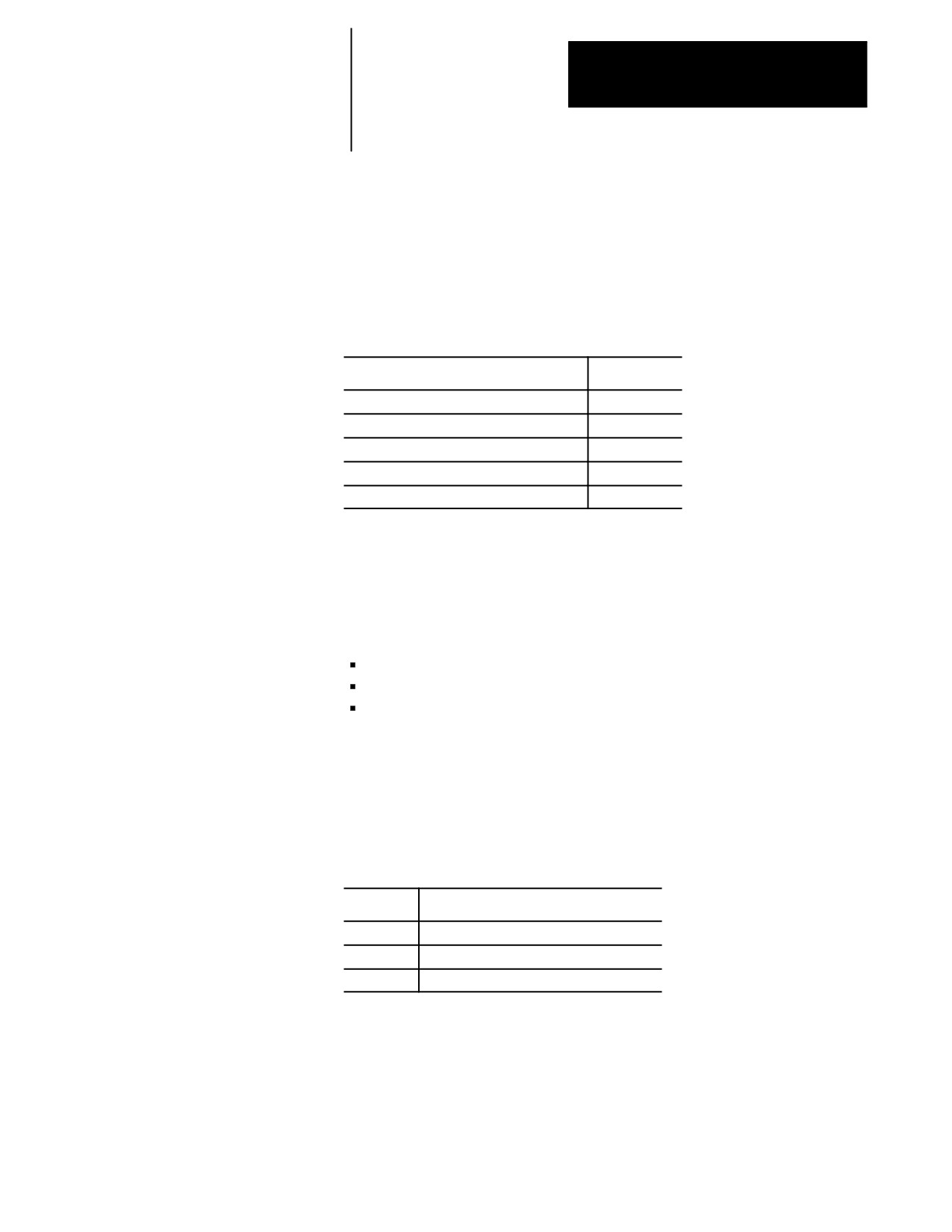
This chapter describes 9/Series coordinate control.
Chapter Overview
For information about:
See page:
Plane selection G17, G18,G19
13-1
Absolute/Incremental modes G90, G91
13-2
Inch/Metric modes G70, G71
13-4
Radius/Diameter modes G07, G08
13-5
Scaling G14, G14.1
13-7
13.1
The 9/Series control has a number of features that operate in specific
planes. For that reason, it is frequently necessary to change the active
Plane Selection
plane by using a G17, G18, or G19 code. The G18 plane is always active
(G17, G18, G19)
at power-up.
Some of the features that are plane-dependant are:
Circular interpolation
Tool tip radius compensation
Many fixed cycle operations
Important: Your system installer determines the axis names and planes
defined by G17, G18, and G19 in AMP. Your system may not have planes
assigned exactly as listed below. Refer to the documentation prepared by
your system installer.
Typical axis names and their corresponding plane assignment are shown
below (this manual assumes this configuration throughout):
Code:
Plane defined by the:
G17
none
G18
Z and X axes (or axes parallel to Z and X)
G19
none
Planes can be altered to accommodate additional axes parallel to the
principle axes by programming those axes in a G17, G18, or G19 block.
See Example 13.1.
13-1
Chapter 13
Coordinate Control
Example 13.1
Altering Planes for Parallel Axes
Assuming the system installer has made the following assignments in AMP:
G18
-- the ZX plane.
U axis -- parallel to Z axis
V axis -- parallel to X axis
Program block
Plane selected
Axis Motion
G18;
selects ZX plane
None
G18 U0;
selects UX plane
U axis moves to zero
G18 V0;
selects ZV plane
V axis moves to zero
G18 U0V0;
selects UV plane
U & V axes move to zero
This manual assumes your system installer has selected the G18 plane to
be activated when an end-of-program block is read (M02 or M30), a
control or E-STOP reset is performed, or power to the control is turned off.
Important: Any axis word in a block with plane select G-codes (G17,
G18, G19) causes axis motion on that axis. If no value is specified with
that axis word, the control assumes a value of zero or generates an error
depending on how your system is AMPed.
13.2
There are two methods for programming axis positioning commands:
Absolute/Incremental Modes
absolute positioning
(G90, G91)
incremental positioning.
In the absolute mode, coordinates are referenced from the zero point of the
active coordinate system. Absolute mode is established by programming a
G90.
G90X40.Z20.;
In the above block, the control moves the axes to a position X40, Z20 as
referenced on the active coordinate system.
G90 is a modal G-code, and it remains active until cancelled by a G91.
In the incremental mode, coordinates are referenced from the current axis
position. Programming a G91 establishes an incremental mode.
G91X40.Z20.;
13-2
Chapter 13
Coordinate Control
In the above block, the control moves the cutting tool away from the
current axis position, a distance of 40 units on the X axis and 20 units on
the Z axis.
G91 is a modal G-code and remains active until cancelled by a G90.
Example 13.2
Absolute vs Incremental Commands
Absolute Command
Incremental Command
G90X20.Z10.;
G91X10.Z-25.;
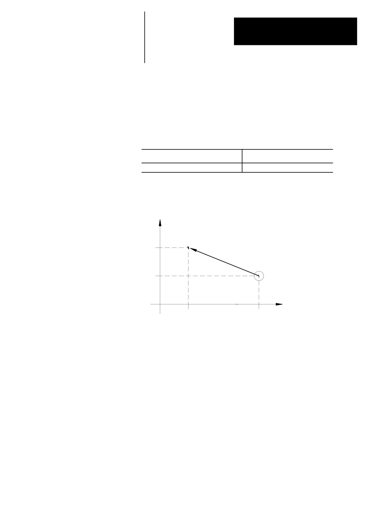
Figure 13.1
Results of Incremental VS Absolute Example
X
End point
20
Start point
10
Z
10
35
Lathe G-code, System A
If using G-code system A, G90 and G91 are not available. To program
moves in absolute mode using G-code system A, call out axis positions
using X, Z, and C axis words.
Important: Absolute and incremental axes addresses are assigned in AMP
by your system installer, and they differ from those shown here.
Absolute command, G code system A
X40.Z20.;
13-3
Chapter 13
Coordinate Control
To program incremental moves using G-code system A, call out axis
positions using U, W, and V.
Incremental command, G code system A
U20.W-25.;
The above commands are not modal. Incremental and absolute commands
can be programmed at any time, even in the same block.
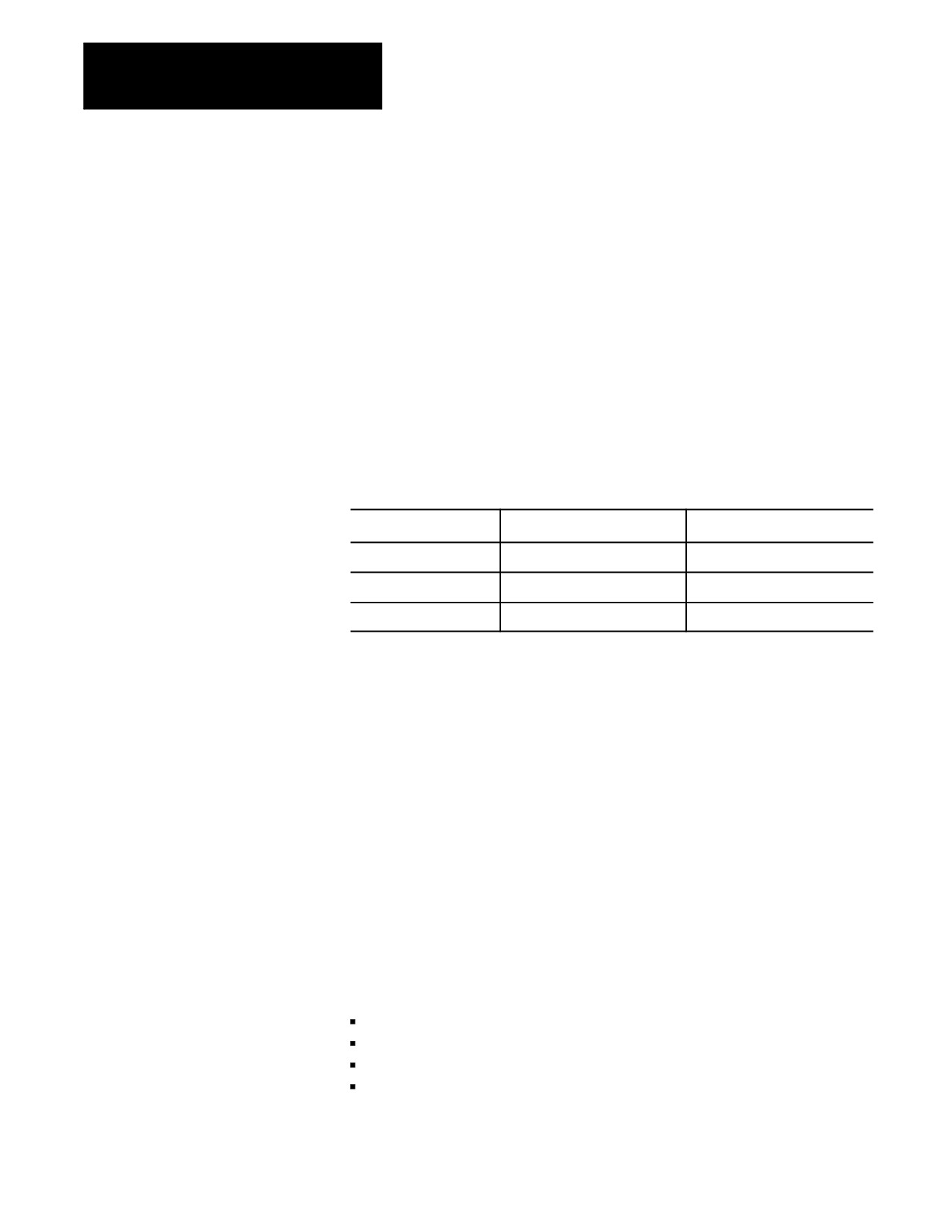
Table 13.A shows the typical command addresses for absolute and
incremental programming in G-code system A. See the documentation
provided by your system installer for axis names in your system.
Table 13.A
Absolute and Incremental Addresses, G-code System A
Absolute Commands
Incremental Commands
Remarks
X
U
X axis motion command
Z
W
Z axis motion command
C
V
C axis motion command
13.3
The selection of a unit system (inch or metric) can be done by
Inch/Metric Modes (G70,
programming either G70 for the inch system or G71 for the metric system.
These unit system G-codes should be among the first blocks written in a
G71)
program.
Both G70 and G71 are modal, and they cancel each other. The default unit
system selected by the control at power-up is determined in AMP by your
system installer.
The currently active unit system is usually displayed on the screen for
softkey level 1 in lines 3 or 4 between the [ ] symbols. If the screen
selected for display of softkey level 1 is the status screen, the active system
G-code (G71 or G70) is displayed among the active system G-codes.
Some of the functions that are affected by the active unit system (inch or
metric) are:
Position commands
Feedrate commands
Axis feed amount for fixed amount feed operation
Unit system for hand pulse generator (HPG)
13-4
Chapter 13
Coordinate Control
13.4
Usually, workpieces on CNC lathes are cylindrical. The control allows
workpiece dimensions programming as either radius or diameter values.
Radius/Diameter Modes
(G07, G08)
G08 places the control in diameter programming mode. This mode
remains active until cancelled by a G07.
G07 places the control in radius programming mode. This mode remains
active until cancelled by a G08.
Either G08 or G07 can be selected by your system installer in AMP to be
the active mode at power-up. The currently active G-code can be
displayed by selecting the status screen. See section 8.1.
If program execution branches to a subprogram that changes to radius or
diameter mode, the control always reverts to the mode of the calling
program when subprogram execution is completed.
Example 13.3
Diameter/Radius Programming
Assume X is the diameter axis
Diameter Programming Mode (G08)
Radius Programming Mode (G07)
Incremental
Incremental
G90G00X0Z35;
G90G00X0Z35;
G91G01F.1X12;
G91G01F.1X6;
Z-10
Z-10
G02Z-4X8I4;
G02Z-4X4I4;
G01Z-15;
G01Z-15;
Absolute
Absolute
G90G00X0Z35;
G90G00X0Z35;
G01F.1X12;
G01F.1X6;
Z25;
Z25;
G02Z21X20I4;
G02Z21X10I4;
G01Z6;
G01Z6;
13-5
Chapter 13
Coordinate Control
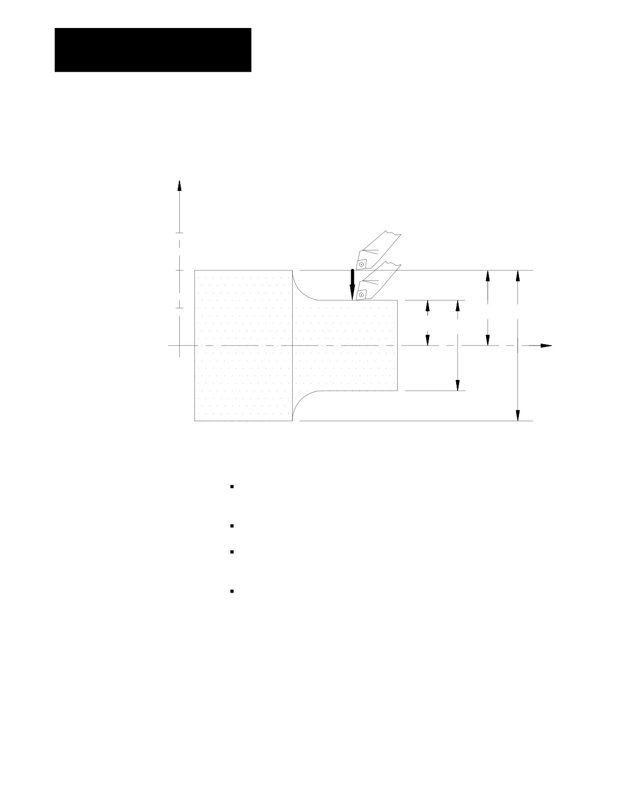
Figure 13.2
Diameter/Radius Programming
Diameter
Radius
Programming Programming
X
Mode (G08) Mode
(G07)
G90G08X12.; G90G07X6
or
or
G91G08X-8.; G91G07X-4.;
15
10
5
10
20
6
12
Z
Important: The following must always be programmed as radius value,
regardless of whether G07 or G08 is active:
Most of the X axis infeed amounts or similar values (addresses D, I, K)
used in Simple and Compound fixed cycles (G70 - G78).
Center point designation (addresses R, I, K) for circular interpolation.
Feedrates in the X-axis direction (change in radius per revolution G95
or radius per minute G94).
The threading cycle parameter E or F when face threading is being
programmed.
Position displays are impacted by radius diameter mode. The
diameter/radius axis selected in AMP displays either an R or a D next to it,
indicating which mode it is currently in and represented on the CRT. This
even applies to the machine coordinate system (absolute display).
13-6
Chapter 13
Coordinate Control
13.5
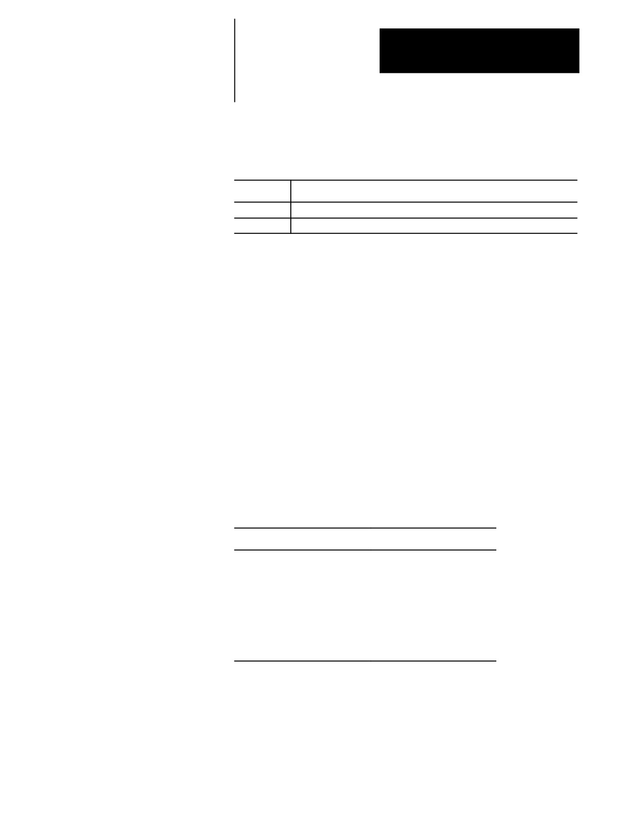
Use the scaling feature to reduce or enlarge a programmed shape. Enable
this feature by programming a G14.1 block as shown below:
Scaling
G14.1 X__ Z__ P__;
Where :
Is :
X and Z
the axis or axes to be scaled and the center of scaling for those axes.
P
the scaling magnification factor for the specified axes.
The axes programmed in the G14.1 block determine which axes are scaled.
The corresponding axis word values specify the center of scaling for each
axis. This position is the axis coordinate around which the scaling
operation is performed.
The scaling magnification factor (P) is the amount of scaling to be applied
to the programmed axes. Each axis can have a different scale factor by
programming them in separate G14.1 blocks. The scaling range is from
0.00001 to 999.99999. A scale factor less than one reduces a programmed
move, while a scale factor greater than one enlarges a programmed move.
If no P-word is programmed or if P0 is programmed in the G14.1 block,
the default magnification factor is used. If the programmed P-word value
is out of range, the CRT displays an error message.
When absolute mode (G90) is active, scaling moves are referenced from
the programmed center of scaling.
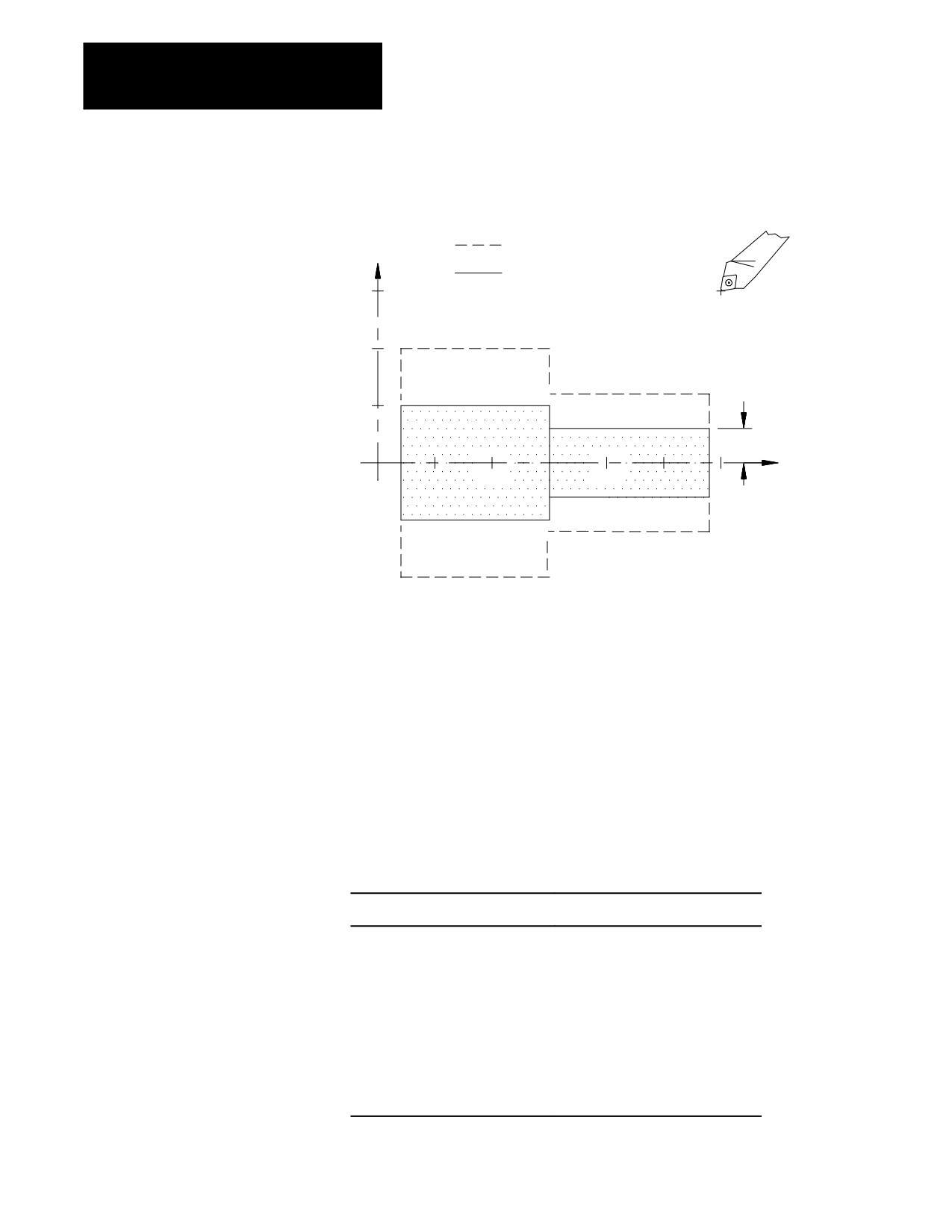
Example 13.4
Scaling with Absolute Mode Active
Program block
Comment
G07 G90 G00 X30. Z60.;
radius mode, absolute mode
G14.1 X0 P.5;
scale X axis only, by .5
G01 X12.;
feedrate move X to X6
Z38.;
feedrate move Z to Z38
X20.;
feedrate move X to X10
G14;
cancel scaling
G00 X30. Z60.;
rapid return
13-7
Chapter 13
Coordinate Control
Figure 13.3
Results of Example 13.4
X
Original part contour
Contour after scaling
X axis only by .5 in
30
G90 absolute mode
20
10
6
Z
20
40
60
When incremental mode (G91) is active, the control ignores the
programmed centers of scaling. The control performs scaling on the axes
programmed in the G14.1 block, but the scaling moves are referenced from
their current axis positions, not the programmed center of scaling or the
active coordinate zero point.
Important: The center of scaling may be specified in either incremental or
absolute mode (G90/G91) in the G14.1 block. But unlike other features in
the control, both modes cannot be programmed in the same block.
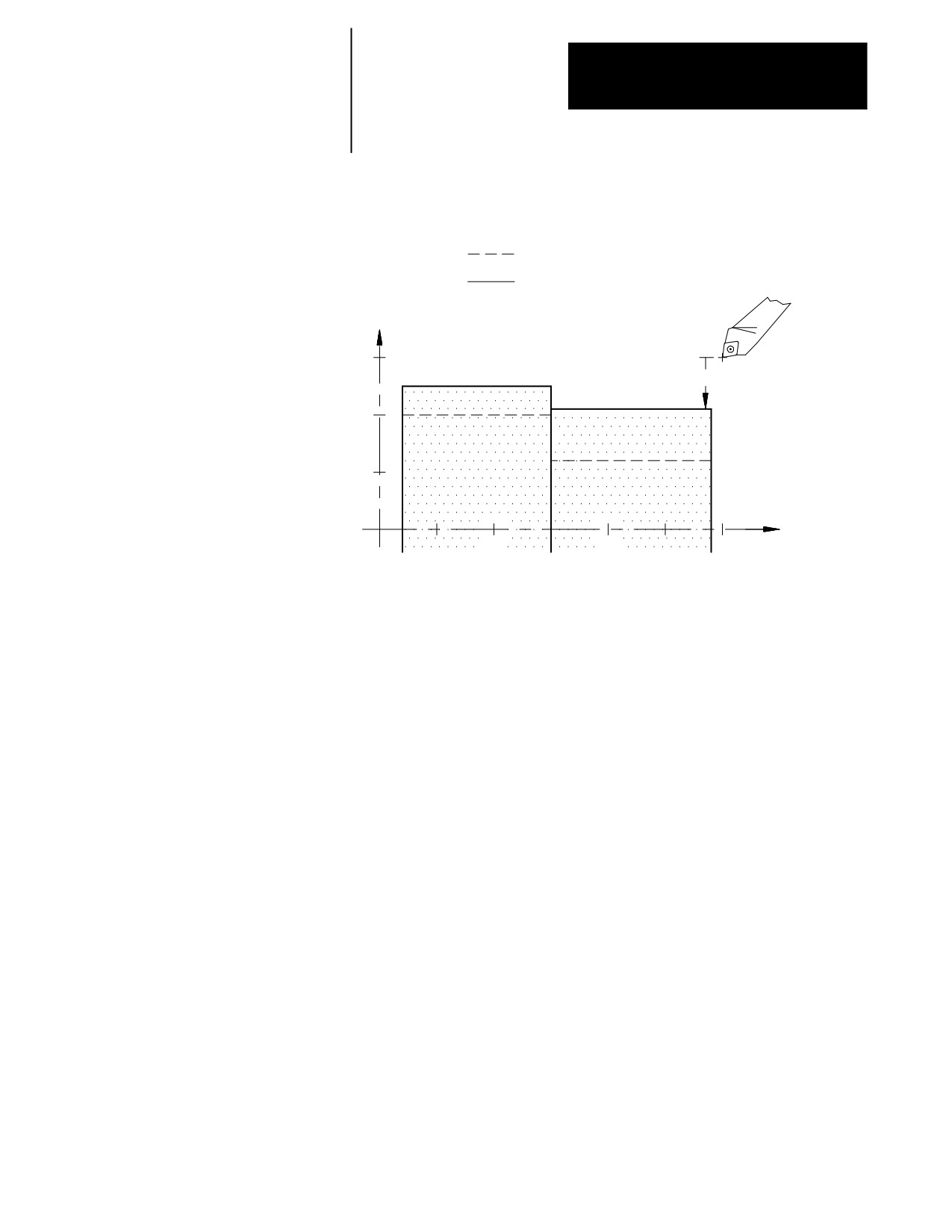
Example 13.5
Scaling with Incremental Mode Active
Program block
Comment
G07 G90 G00 X30. Z60.;
radius mode, absolute mode
G91;
incremental mode
G14.1 X1.023 P.5;
scale X by .5 (X value is ignored)
G01 X-18.;
feedrate move X to X21
Z-22.;
feedrate move Z to Z38
X8.;
feedrate move X to X25
G14;
cancel scaling
G00 X5. Z30.;
rapid return
13-8
Chapter 13
Coordinate Control
Figure 13.4
Results of Example 13.5
Original part contour
Contour after scaling
X axis only by .5 in
G91 incremental mode
X
30
--9
20
10
Z
20
40
60
G14 disables scaling on all axes. When you disable scaling, the center of
scaling and any scaling magnification factors are cleared. The next time
you enable scaling, these values must be reset. In addition to G14, M99 in
the main program, M02, M30, and a control reset operation disables
scaling. The system powers up with scaling disabled.
Your system installer specifies in AMP, on an axis by axis basis, whether
scaling is allowed. Refer to the literature provided by your system installer
for additional information.
The control provides the PAL program with the option of monitoring
which axes are currently being scaled, on an axis-by-axis basis, through the
PAL flag $SCAX. See the PAL Reference manual for additional
information.
13-9
Chapter 13
Coordinate Control
13.5.1
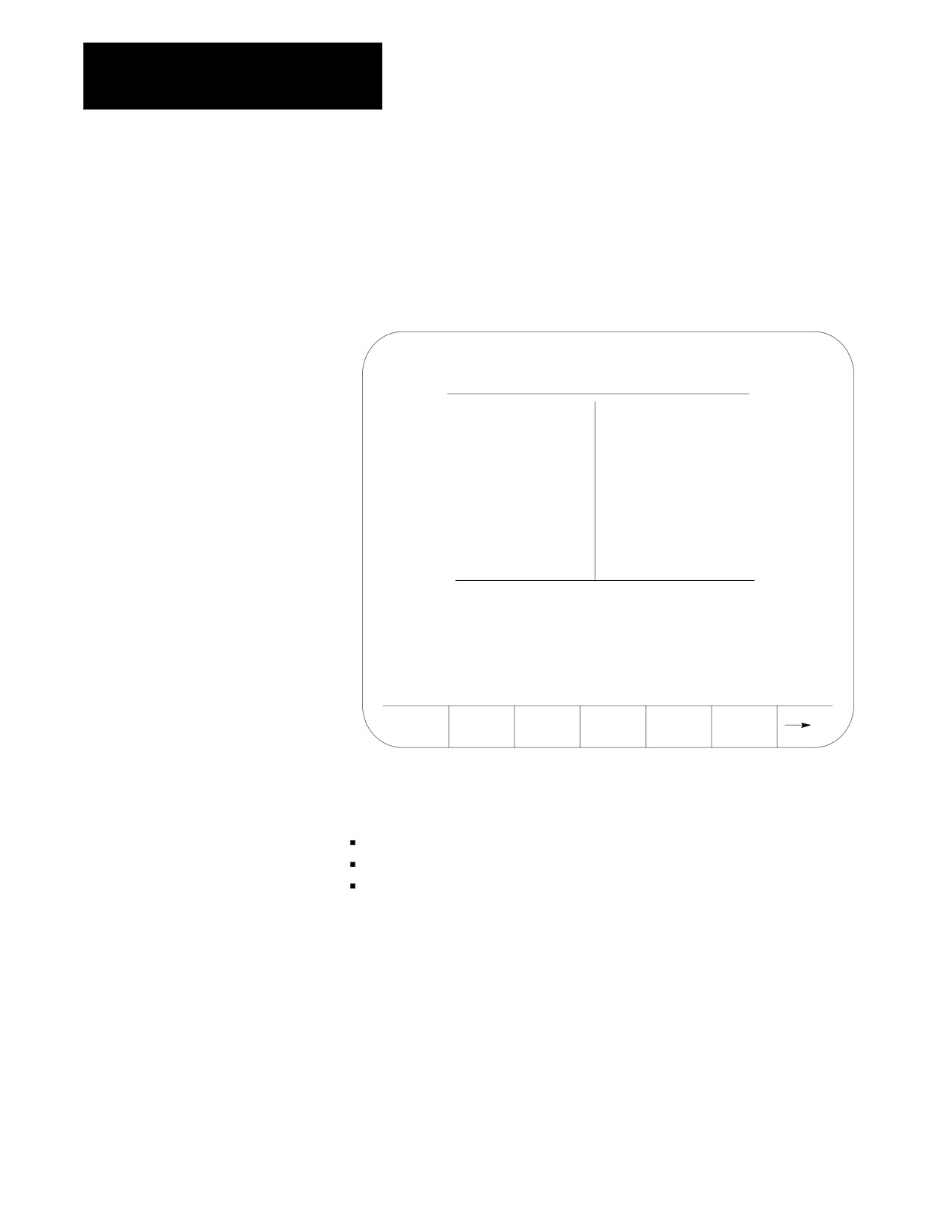
When you enable scaling for a particular axis, the letter “P” is displayed
next to the axis name on all axis position display screens. Figure 13.5
Scaling and Axis Position
shows scaling enabled on all axes.
Display Screens
Figure 13.5
Axis Position Display Screen Showing Scaling Enabled
E-STOP
PROGRAM[ MM
]
F
0.000 MMPM
PR
X
1234.567
S
00
P
Z
9876.000
T
0
(ACTIVE PROGRAM NAME)
MEMORY
MAN STOP
PRGRAM
OFFSET
MACRO
PRGRAM
SYSTEM
MANAGE
PARAM
CHECK
SUPORT
13.5.2
The scaling magnification data screen lists for all axes, the:
Scaling Magnification Data
currently active scaling magnification amount
Screen
current center of scaling
default scaling magnification amount
The currently active scaling magnification amount and the current center
of scaling for the axes can only be monitored through this screen. The
default scaling magnification amount for the axes can be monitored or
changed through this screen.
The default scaling magnification values should be changed only when the
control is in a stopped state. If the default values are changed, the new
default values do not become active until the next G14.1 block is executed.
13-10
Chapter 13
Coordinate Control
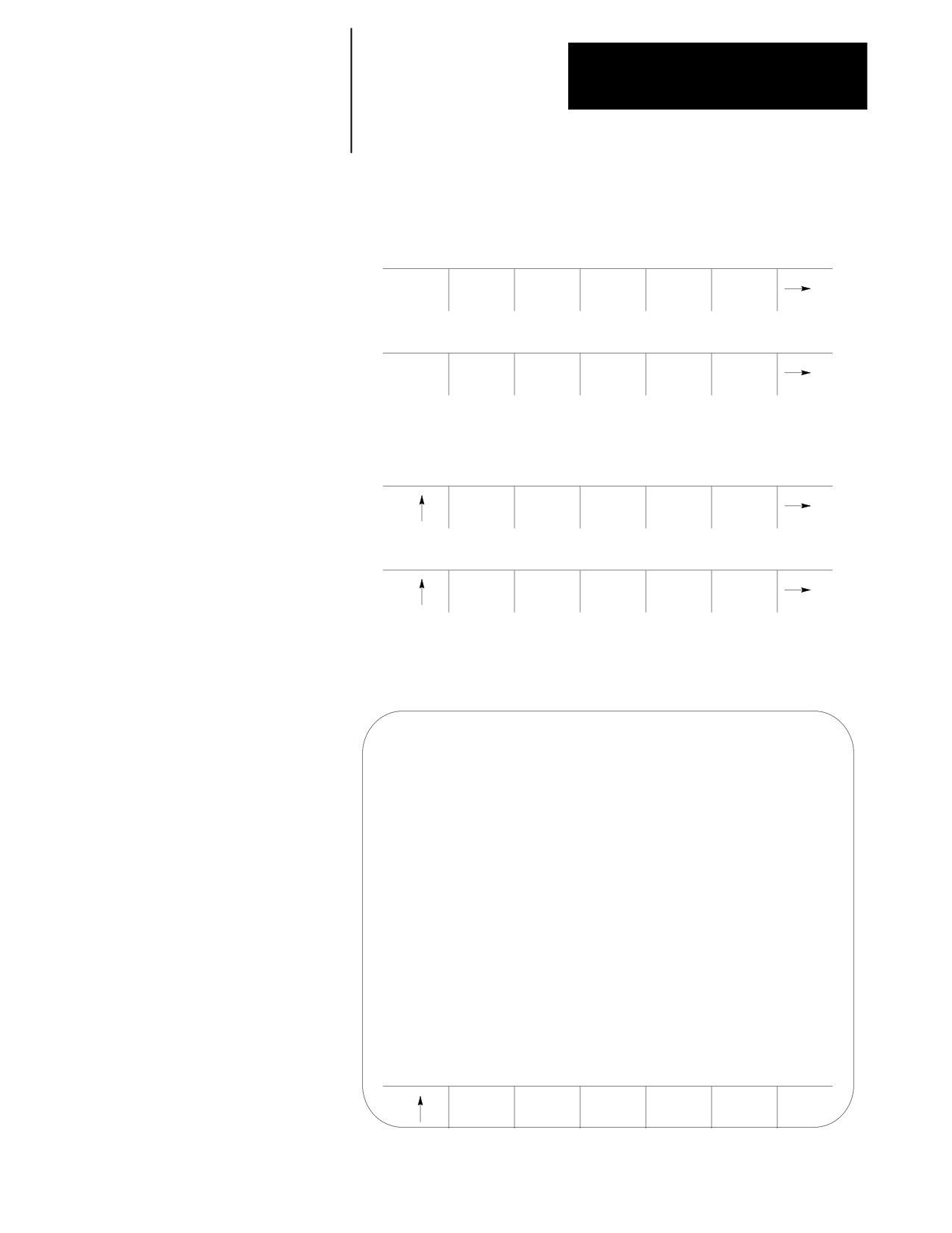
To access the scaling magnification data screen, follow these steps:
1.
Press the {OFFSET} softkey on the main menu screen.
(softkey level 1)
PRGRAM
OFFSET
MACRO
PRGRAM
SYSTEM
MANAGE
PARAM
CHECK
SUPORT
FRONT
ERROR
PASS-
SWITCH
PANEL
MESAGE
WORD
LANG
2.
Press the {SCALNG} softkey to display the scaling magnification
data screen. See Figure 13.6.
(softkey level 2)
WORK
TOOL
TOOL
TOOL
RANDOM
CO-ORD
WEAR
GEOMET
MANAGE
TOOL
COORD
SCALNG
BACKUP
ROTATE
OFFSET
Figure 13.6
Scaling Magnification Data Screen
SCALING MAGNIFICATION
CENTER
CURRENT
DEFAULT
X
+ 123.00000
2.00000
1.00000
Z
+ 123.00000
2.00000
1.00000
REPLCE
VALUE
13-11
Chapter 13
Coordinate Control
Important: If an axis is configured as a rotary axis, the scaling
magnification display screen displays dashes instead of numbers for that
axis.
Rotary axes cannot be scaled.
The left column lists the current center of scaling for each axis.
When scaling is cancelled, the current center of scaling for each axis
is set to zero. The format of this value is determined by the word
format of the selected axis.
The middle column lists the currently active scaling magnification
value for each axis. When scaling is cancelled, the current scaling
magnification value for each axis is set to 1.00000.
The right column lists the current scaling magnification default value
for each axis. This value is used if P is not programmed or if P0 is
programmed in the G14.1 block. The range of the default value is
0.00001 to 999.99999 with a word format of 3.5. The default values
are stored in memory when the control is powered down. When the
control is powered up, these values are restored from memory.
3.
Use the up or down cursor keys to move the block cursor to the
default value to be changed. The selected default value appears in
reverse video.
4.
To replace stored default scaling magnification value, key in the new
default value and press the {REPLCE VALUE} softkey.
13.5.3
While scaling is enabled, these restrictions apply:
Scaling Restrictions
Scaling affects only programmed axis motion. All manual axis motions
and PAL axis mover motions are performed at full scale.
Scaling does not affect M-, F-, S-, T-, and B-word functions. The
F-word is scaled if the control is in inverse time mode (G93). Scaling
while in inverse time mode is applied as follows:
Programmed F word
Scaled F word
(when in G93 mode)
= ----------------------
Largest Scale Factor
Scaling is disabled during G27, G28, and G30 automatic home
operations. For a G29 automatic return from home operation, scaling is
re-enabled after the intermediate point is reached.
13-12
Chapter 13
Coordinate Control
When changing work coordinates (G54-G59.3), the center of scaling is
transferred from the old work coordinate system to the new work
coordinate system. The offset distance from the tool position in the old
work coordinate system to the tool position in the new work coordinate
system is not scaled.
Scaling is applied to G52 and G92 offsets. The center of scaling shifts
when the work coordinate systems are shifted by a G92 offset or by
changing coordinate offset values. When using a G52 offset, the center
of scaling is adjusted to the new local coordinate systems.
Scaling is not applied to these offsets:
- external
- tool wear
- tool geometry
- tool radius
- tool length
Scaling is not applied to blocks containing:
- dwells (G04)
- data setting codes (G10., G10.1)
- macro calls (G56, G66, G66.1)
In the case of macro calls, the data passed via local parameters is not
scaled unless the data is used inside of the macro for motion.
G22, programmable zone 2 check on and data setting, is not scaled.
G53, absolute positions moves, is not scaled.
Rotary axes cannot be scaled.
In circular mode, the scale factors for the axes of the active plane have
to be the same. The control generates an error if the scale factors of the
axes are not equal.
Scaling is applied to these fixed cycles as shown below. The axis letters
may vary depending on how AMP is configured.
G31, G31.1 - G31.4
Gxx X__Z__
X (scaled)
Z (scaled)
13-13
Chapter 13
Coordinate Control
G37, G37.1 - G37.4
Gxx Z__
Z (scaled)
G73, G74, G76, G82, G83, G84
G85, G86, G87, G88, G89
Gxx X__ Y__ Z__R__I__Q__K__P__F__L__
X (scaled)
Y (scaled)
Z (scaled)
R (scaled)
I
(not scaled)
Q (not scaled)
K (not scaled)
P (not scaled)
F (not scaled)
L (not scaled)
Important: R uses the scale factor associated with the axis that is
perpendicular to the active plane.
These cycles assume that Lathe type C is selected:
G73, G74, G75
Scaling is not applied to the block containing the G-code. Scaling is
applied to the contour blocks defining the workpiece.
G76, G77
Gxx X__Z__I__K__F__D__
X (scaled)
Z (scaled)
I
(scaled)
K (not scaled)
F (not scaled)
D (not scaled)
13-14
Chapter 13
Coordinate Control
G78
G78 X__Z__K__D__F__E__A__P__I__
X (scaled)
Z (scaled)
K (not scaled)
D (not scaled)
F (not scaled)
E (not scaled)
A (not scaled)
P (not scaled)
I
(scaled)
G33
G33 Z_F_E_Q
G33 X_Z_F_E_Q
G33 X_F_E_Q
X (scaled)
Z (scaled)
E (not scaled)
F (not scaled)
Q (not scaled)
G34
G34 Z_F_E_Q K
G34 X_Z_F_E_Q K
G34 X_F_E_Q K
X (scaled)
Z (scaled)
E (not scaled)
F (not scaled)
Q (not scaled)
K (scaled)
G20
G20 X_Z_I_
X (scaled)
Z (scaled)
I
(scaled)
13-15
Chapter 13
Coordinate Control
CAUTION: This cycle cuts more metal when scaling is
enabled.
G21
G21 X_Z_F_E_
X (scaled)
Z (scaled)
F (not scaled)
E (not scaled)
G24
G24 X_Z_K_
X (scaled)
Z (scaled)
K (scaled)
CAUTION: This cycle cuts more metal when scaling is
enabled.
G81
G81 X_Z_R F_L_
X (scaled)
Z (scaled)
R (scaled)
F (not scaled)
L (not scaled)
Important: R uses the scale factor associated with the axis that is
perpendicular to the active plane.
END OF CHAPTER
13-16
Chapter
14
Axis Motion
14.0
This chapter covers the group of G-words that generates axis motion or
dwell data blocks. Major topics include:
Chapter Overview
Information about:
On page:
Positioning axes
14-1
Automatic machine home
14-12
Dwell (G04)
14-18
Programmable mirror image
14-19
Axis clamp
14-22
14.1
Use these 4 basic G-codes to produce axis motion:
Positioning Axes
G00 Rapid Positioning
G01 Linear interpolation
G02 Circular interpolation (clockwise)
G03 Circular interpolation (counterclockwise)
After the execution of a positioning command the program proceeds to the
next block only after an in-position check function confirms that all
commanded axes have reached the in-position band. Your system installer
sets the in-position band width in AMP. See chapter 18 for details on the
G-codes that you can use to modify the in-position band check.
14.1.1
Format for the rapid positioning mode is:
Rapid Positioning Mode
G00X__ Z__ ;
(G00)
Where :
Is :
G00
The G00 code establishes the positioning mode. In positioning mode, the cutting
tool is fed along a straight line at the rapid feedrate determined in AMP by your
system installer.
XZ
The end point of the move generated by the G00 block in the current work
coordinate system.
You can perform a rapid positioning in the absolute mode (G90), or the
incremental mode (G91).
14-1
Chapter 14
Axis Motion
Your system installer determines the feedrate for the rapid positioning
mode in AMP, individually for each axis. The feedrate of a positioning
move that drives more than one axis is limited by the rapid rate set for the
slower axis. The slower axis is driven at its rapid rate, while the feedrate
for other axes is reduced to maintain a linear move. This also assures that
all axes start and stop at the same time.
G00 is a modal command and remains in effect until it is cancelled by a
G-code of the same group. For a listing of G-code groups, see appendix C.
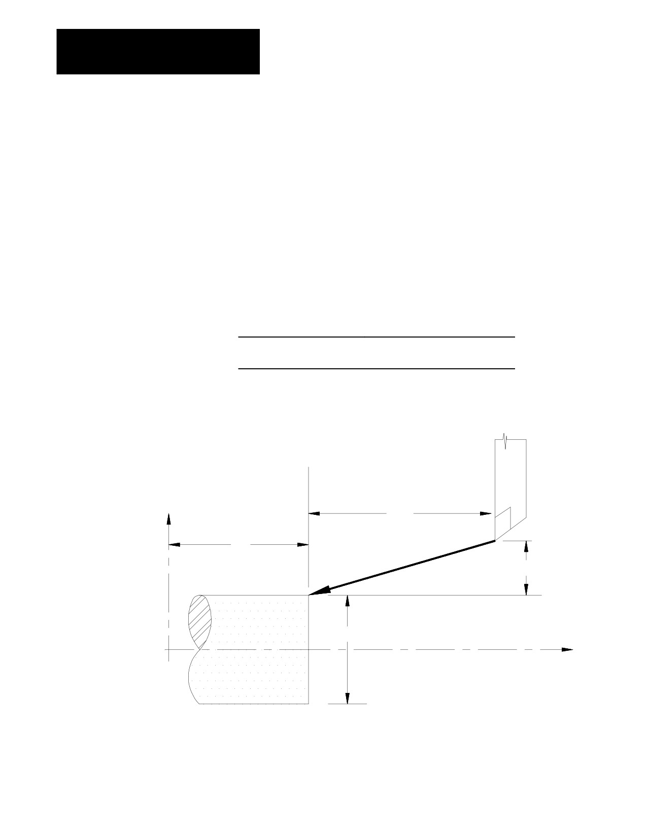
Example 14.1
Positioning (G00)
Absolute command
Incremental command
G08
G08
G90G00X75.Z55.;
G91G00X-35.Z-80.;
Figure 14.1
G00 Positioning, Results of Example 14.1
X
80
55
35
75
Z
Important: Any F-word designated in the positioning mode is stored as
the active feedrate in control memory, but it is ignored during positioning
mode (G00).
14-2