9/Series CNC Lathe. Operation and Programming Manual - page 10
Chapter 10
Introduction to Programming
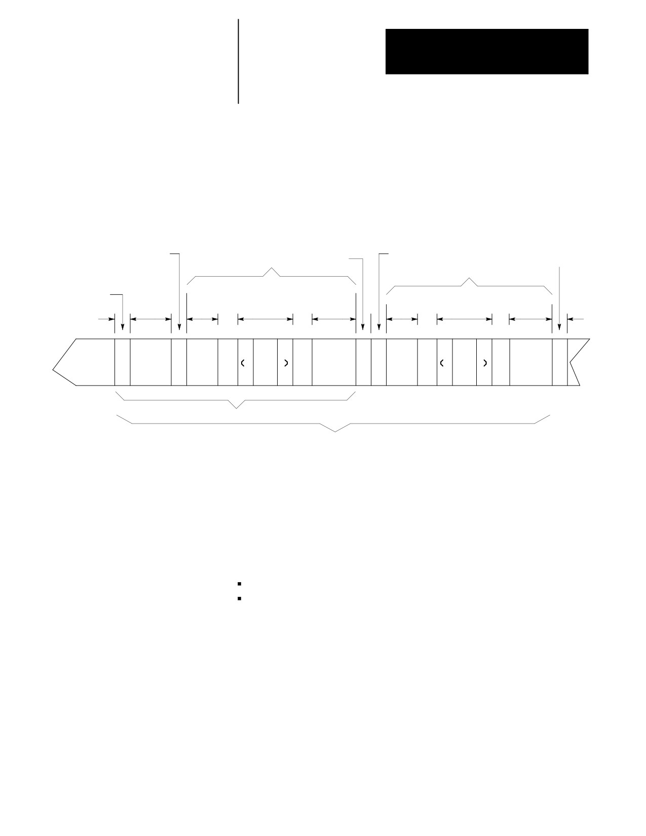
Tape with Program End = % (ASCII), ER (EIA)
Unlike the previous tape type mentioned, this type of tape accepts only the
“%” (ER) field as the program end code. See Figure 10.2. See chapter 10
for details on legal program end codes and the effect of STOP PRG END.
Figure 10.2
Tape Configuration (Program End = % (ASCII), ER (EIA))
Program start code
1 foot
Program start code
Tape end
Part program
space
code
Part program
Tape start
Program
code
Leader
Comment
Program
Program
Program
name
Comment
section
(opt)
end code
name (opt)
end code
(opt)
(opt)
E
E
ER
ER
%
%
or
O
O100
or
O
O101
or
or
%
B
ER
B
ER
%
Typical single program tape
Typical multi-program tape
This tape format conforms to the variable block length format specified by
EIA standard RS-274D.
The control automatically recognizes EIA or ASCII during input when it
reads the first EOB code from the tape.
(1) Tape Start (Rewind, Stop Code)
The tape start code, indicating the beginning of a tape, is designated with:
% character ---- ASCII format
ER ---- EIA format
This code must be on the tape if you program a tape rewind code (M30,
M99) in the part program. In other cases (M02, %), it is not necessary to
have this code on the tape. Any tape punched from the 9/Series control
has the tape start code.
10-3
Chapter 10
Introduction to Programming
(2) Leader Section
The information between the tape start and the program start is called the
tape leader section. The leader section is a tape indexing section. On
punched tape, the holes punched in the leader section can be configured to
show alphanumeric characters. The control ignores information within the
leader section and does not perform a parity check on this information.
Important: A program start code must not appear within the leader
section. If the program start code appears, the control starts reading
information and assumes that it is the part program. This causes parity
errors or “nonsense” codes to be read in by the control.
(3) Program Start Code
The first end-of-block code (EOB code) after the leader section indicates
the beginning of the part program. The EOB code is designated with:
line feed (LF) ---- ASCII format
carriage return (CR) ---- EIA format
Important: When performing an EOB search, the search is executed from
the beginning of the part program, NOT from the point of display.
(4) O-Word Program Name
The program name, if on the tape, must follow the program start code.
When outputting to tape the program name can be determined by:
Program Name:
If:
Manually keying in the program name
-- --
Selected from the first block of the
No name has been manually keyed in and the first
program
block contains an O-word, : (for EAI format), or N-word
after the program start code.
Selected from the program directory
No name has been manually keyed in and no name
exists in the first block of the program. For the program
name to be taken from the directory screen the program
must be stored on that directory with the letter O
followed by up to 5 numeric digits. In this case the
control generates an O-word block as the first block of
the program written to tape.
No name is used
A program will be stored on tape with no program name
if none of the above naming conditions are met.
(5) Part Program Section
A part program is made of blocks of information. Individual blocks
contain words that the control can interpret. Individual words are made up
of an address with a numeric value. For details on words and addresses,
see the remaining sections of this chapter.
10-4

Chapter 10
Introduction to Programming
This section should include a program name, program blocks, comments,
and end-of-program. Each block in the part program is separated by an
EOB code. The control displays a semicolon “;” to indicate the presence
of an EOB code.
Important: When performing an EOB search, the search is executed from
the beginning of the part program, NOT from the point of display.
(6) Comment
Information punched between the control out code “(” and the control in
code “)” within the program section is considered a comment, and it is not
handled as significant information (even though it is copied to and from
control memory or tape). Any number of comments can be included in a
part program, interspersed with program blocks or words.
Example 10.1
Comments in Part Programs
X1.Z1.(START MOTION);
(CALL SUBPROGRAM 1);
(12345);
Each of the above program blocks contains a comment. The control does
not regard the comment as significant information, except when it appears
in the first block of the program. In this case, the comment is displayed on
the program directory screen as part of the program name.
The comment can be up to 128 characters long (including the control out
and control in codes), and it can consist of any alphanumeric characters
and special symbols. The comment cannot include the following codes:
(
)
ER, %
(rewind stop codes)
EOB
(end of block)
Important: If rewind stop codes are included in the comment, the tape
rewind function (M30) causes the rewind to stop in the comment section of
the tape.
(7) Program End
The control stops reading the part program when it reads a program end
code. The following codes can be used as program end codes:
Code:
Description:
M02
end of program
M30
end of program and tape rewind
M99
end of program, tape rewind, and restart the program
%
end of program and end of tape code
PRGRM NAME
end of program
10-5
Chapter 10
Introduction to Programming
(8) Tape End (Rewind, Stop Code)
The tape end code, indicating the end of a tape, is designated with either:
Code:
Description:
%
ASCII format
ER
EIA format
10.2
Each individual machining operation performed by the control is
Program Configuration
determined by the control’s interpretation of a group of words or codes
(commands) called a “block.” Individual blocks in a part program define
each machining process. Part programs consist of a number of blocks that
define a complete operation of a part.
Part program blocks are made up of:
Component of
Description:
program block:
character
a number, a letter, or a symbol that means something specific to the
control. For example, 1 G ; are characters that the control recognizes
as meaningful information.
address
a letter that defines the instruction for the control. Examples of addresses
are: G, X, Z, F.
word
an address followed by a numeric value. Examples of words are: G01,
X10.5, F.1., M2. Each word requires a specific format for its numeric part.
These formats are given on page 10-20 .
code
industry standards for many of the G- and M-codes used here. For that
reason, they are often referred to as G- or M- “codes.”
parameter
a number of fixed cycles that are initiated by a specific G-code. Other
words appearing in those G-code blocks are referred to as “parameters”
because their values are relevant only to that G-code. For example, a
Z-word generally refers to a Z axis move, but when it appears in a block
with a G83 peck drilling cycle, its value refers to the depth of the hole to
be drilled. In that case, it is a “parameter”of the G83 fixed cycle.
10-6
Chapter 10
Introduction to Programming
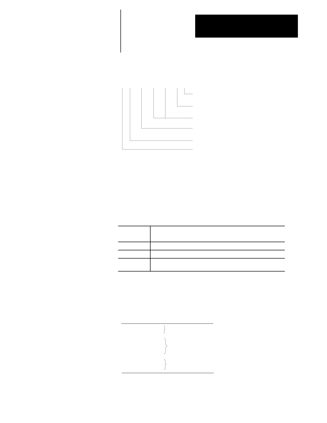
A block is a set of words and characters that defines the operations of the
control. For example:
/ N3
G00
X10. Z10. M3 ;
end of block character
miscellaneous function word
(spindle on forward)
axis movement words
preparatory function word
(rapid positioning mode)
sequence number word
optional block delete character
The 9/Series control sequentially executes blocks in a part program to
conduct the required machining operation.
Important: To make jumps, loops, or calculations within an executing
program or subprogram, use the paramacro features described in chapter
28.
A part program has a:
Part program
Description:
section:
Beginning
sets up the control and the machine to perform the operations wanted
Middle
performs the machining operations
End
returns the machine to a safe stop position, and preparing the control for
the next part program
The blocks programmed vary for each section of the program. As an
example, consider the following simple example program.
Example 10.2
Sample Part Program
G91G21;
beginning
G00X28.;
G33Z-64.E4.;
middle
G00X5;
Z2.;
end
M02;
10-7
Chapter 10
Introduction to Programming
10.2.1
You can enter up to 8 alphanumeric characters for program names.
Program Names
Subprograms are designated with the letter O followed by 5 numbers. If
you enter a new program name with 5 numeric characters, the control
assumes that it is a subprogram and automatically inserts the letter O as the
first character in the name. The control does not consider programs with
more than 5 numeric characters as subprograms.
The control lists subprograms in numerical order from lowest to highest.
The main programs are listed in alphabetical order, following the
subprograms.
Entering Program Names
To enter a program name:
1.
Press the softkey {PROGRAM MANAGE}. This calls up the
program directory, which lists subprograms first, then programs by
alphabetical order.
2.
Type in the name of a new program or one already listed. You cannot
enter spaces or special characters.
3.
Press {EDIT}. This initiates the editing mode for the program
selected.
Important: When the control reads a program from tape, the O-word is
the program name. If there is no O-word, the control interprets the first
sequence number as the program name.
Example 10.3
Entering Subprogram Names
Name entered
Program name stored by control
O00123
O00123
O123
O00123
123
O00123
12345
O12345
Example 10.4
Legal Program Name Blocks
O12345;
O12345(TAPPING PROGRAM);
O333
O2;
10-8
Chapter 10
Introduction to Programming
10.2.2
Each block in a part program can be assigned a sequence number to
distinguish one block from another. Sequence numbers begin with an N
Sequence Numbers
address, followed by a one to five digit numeric value.
Sequence numbers can be assigned at random to specific blocks or to all
blocks. If you assign sequence numbers to locks, you can designate their
sequence numbers. Sequence numbers are necessary to make program
jumps and to specify a block for paramacro calls and returns.
Below is an example of two blocks with sequence numbers 10000 and
10010.
N10000 X5. Z4.
;
N10010 X2. Z2.
;
When you assign sequence numbers to blocks the N-word comes first in
the block except when you designate block delete. See page 10-10. It is
not necessary to program the N-word first in the block. The control still
finds it for jumps; however, it will not find renumber operations.
If more than one N-word is in a block, the control uses only the first
N-word encountered for that block number.
Different blocks can be assigned the same sequence number. If this
number is called by a “GOTO” or some other command, the first block
found by the control with the sequence number that is closest to the calling
block is used. The control first searches for the sequence number in the
forward direction (from the calling block), then it searches in the reverse
direction (from the calling block). How the control reacts if the sequence
number is not found is determined by the specific operation being used.
The control has a programming feature that renumbers existing sequence
numbers or assigns all block sequence numbers.
10.2.3
Information between the control out code “(” and the control in code “)”
within a part program is regarded as a comment, and it is not handled as
Comment Blocks
significant information. The comment can be described in up to 128
characters (including the control out/in codes), consisting of alphanumeric
characters and special symbols.
Example 10.5
Program Block With Comment
N00010G91X5.(CHANGE TO INC. MOVE X 5);
10-9
Chapter 10
Introduction to Programming
10.2.4
When you program a slash “/” followed by a numeric value (1-9)
anywhere in a block, the control skips (does not execute) all remaining
Block Delete and Multi Level
programmed commands. The block delete feature is turned on with the
Delete
{FRONT PANEL} softkey or with an optionally installed switch on the
MTB panel. If the {FRONT PANEL} softkey is used, only block delete /1
is available.
Your system installer determines in AMP if the entire block is deleted or if
only the characters to the right of the block delete / are deleted. If the
entire block is to be deleted, it is done regardless of the position of the /
character in the block.
Example 10.6
Block Delete in a Part Program
Program Block
Comment
N1000 X__ Z__;
first block
N1010
Z__;
second block
/1N1020 X__;
control skips this block if switch 1 is on
/1/2N1030 X__;
control skips this block if switch 1 or switch 2 are on
/N1032 X__;
control skips this block if switch 1 is on
N1040 X__;
/2N1050 X__;
control skips this block if switch 2 is on
The control always reads several blocks into its buffer memory so that it
can prepare for moves and commands before it executes them. The switch
(or softkey) controlling a block delete must be set before that block is read
into buffer memory, otherwise it will not be skipped.
The control considers a “/” without a number to mean “/1.” However, “/1”
must be programmed if more than one block delete number is to be used in
a block.
The block delete is active for sequence number search and dry run
operations.
The control ignores the block delete when you load a part program from
tape or another device into control memory. The control also ignores the
block delete when a part program is saved on punched tape or another
device from control memory.
For details on the block delete switch(s), see the PAL reference manual and
the documentation prepared by your system installer.
10-10
Chapter 10
Introduction to Programming
10.2.5
All program blocks must have an end of block statement as the last
character in the block. This character tells the control how to separate data
End of Block Statement
into blocks. The control uses the “;” to mark the end of a block.
Important: When performing an EOB search, the search is executed from
the beginning of the part program, NOT from the point of display.
To specify an end of block character “;” at the keyboard use the [EOB] key
on the operator panel. If you are editing part programs off line you cannot
enter the end of block character when blocks are keyed in. See chapter 7.
The control automatically inserts end of block “;” when the program is
downloaded.
10.3
When the same series of blocks is repeated more than once it is usually
easier to program them using a subprogram.
Using Subprograms
The key difference between a subprogram and a G65 paramacro is that a
paramacro always gets a new set of local parameters. A subprogram uses
the same set of local parameters that the main program used. See chapter
28 for details on paramacros and local parameters.
This section explains:
Main and subprograms
Subprogram calls
Important: To make jumps, loops, or calculations within an executing
program or subprogram, use any of the paramacro features described in
chapter 28.
You can call a subprogram in an MDI command; however, a MDI
command cannot contain an M99 code.
CAUTION: Any edits that you make to a subprogram or
paramacro program (as described on page 5-4) that have already
been called for automatic execution are ignored until the calling
program is disabled and reactivated. Subprograms and
paramacros are called for automatic execution the instant that
the calling program is selected as active (as described on page
7-6).
10-11
Chapter 10
Introduction to Programming
10.3.1
Generally, programs are executed sequentially. When you enter an
M98Pnnnnn command (“nnnnn” representing a subprogram number) in a
Subprogram Call (M98)
program, the control merges the subprogram (designated by the address P)
before the block that immediately follows the M98 command. The control
issues the error message “CANNOT OPEN SUBPROGRAM”, if it cannot
find the subprogram designated by the M98 command.
For example,
M98 P00001 ;
would cause execution to transfer from the current program to the
subprogram numbered 00001.
Important: For a program to be used as a subprogram it must have a
program name starting with the letter O followed by up to a 5 digit
numeric value. When calling the subprogram with a P-word only the
numeric value is used. The letter O is omitted.
You might want to execute a subprogram more than one time. For
example,
M98PnnnnnLmm;
would cause the subprogram numbered nnnnn to be merged in the main
program mm times. When you enter an L command in a M98 command,
the control merges the subprogram (designated by the address P) before the
block that immediately follows the M98 command as many times as
designated by the L-word. Both the P- and L-words must follow the M98
command in a program block.
Omission of an L-word is regarded as L1. An L-word cannot be a negative
value or have a value of zero.
Important: If M02 or M30 codes are found in a subprogram before the
program reads an M99, execution stops. The program resets or rewinds if
an M30 code is executed, or the program ends if the M02 code is executed.
10-12
Chapter 10
Introduction to Programming
10.3.2
M99 code acts as a return command in both sub- and main programs;
however, there are specific differences:
Main and Subprogram
Return (M99)
Using M99 in a Main Program
If you use M99
M99:
in a:
Main program
executes all commands in the block, regardless if information
is programmed in the block to the right of the M99 command
clears all modal codes similar to an M02 or M30 (simulates
start-up conditions)
resets the current main program to the first block
automatically performs a cycle start on the program after it is
reset and program execution starts over.
Subprogram
tells the control the end of a subprogram
will not merge any commands within a file that is used as a
subprogram and follows a M99 code in the main program into
the calling program.
Using M99 in a Subprogram
Program the M99 code anywhere in a program block, provided no axis
words are programmed to the left of M99. Any information (other than
axis words) programmed to the left of M99 is executed as part of the
subprogram, while information (including axis words) programmed in the
block to the right of the M99 command is ignored.
If you program:
Then:
M99X10;
X10 is ignored in this subprogram block
X10M99;
X10 generates an error in this subprogram
M03M99;
M03 is executed as normal in this subprogram
10-13
Chapter 10
Introduction to Programming
Example 10.7
Subprogram Calls and Returns
MAIN PROGRAM
SUBPROGRAM 1
SUBPROGRAM 2
(MAIN PROGRAM);
(SUBPROGRAM 1);
(SUBPROGRAM 2);
N00010...;
N00110;
N00210;
N00020...;
N00120...;
N00220...M99;
N00030M98P1;
N00130M99;
N00040...;
N00140...;
N00050...;
N00150M30;
N00060M98P2L2;
N00070M30;
This path of execution results when you select the main program in
Example 10.7 as the active program:
(MAIN PROGRAM);
N00010...;
N00020...;
N00030M98P1;
(SUBPROGRAM 1);
N00110;
N00120...;
N00130M99;
N00040...;
N00050...;
N00060M98P2L2;
(SUBPROGRAM 2);
N00210;
N00220...M99;
(SUBPROGRAM 2);
NOO210;
N00220...M99;
N00070M30;
10-14

Chapter 10
Introduction to Programming
10.3.3
We use the term nesting to describe one program calling another. The
program called is a nested program. When a subprogram is called from the
Subprogram Nesting
main program it is on the first nesting level or nesting level 1. If that
subprogram in turn calls another subprogram, the called subprogram is in
nesting level 2. Subprograms can be nested up to a maximum of 4 levels.
Figure 10.3
Subprogram Nesting
Main
Sub-
Sub-
Sub-
Sub-
program
program 1
program 2
program 3
program 4
0 00001;
0 11111;
0 22222;
0 33333;
0 44444;
M98P11111;
M98P33333;
M98P22222;
M98P44444;
M02;p
M99;
M99;
M99;
M99;
Level 1
Level 2
Level 3
Level 4
Important: Calling a macro does not add to the nesting level of any active
subprograms. Up to 4 subprograms can still be nested, but the combined
total of nested macros and subprograms cannot exceed 8. See chapter 28
for information on macros.
10-15
Chapter 10
Introduction to Programming
10.4
Words in a part program consist of addresses and numeric values.
Word Formats and
Functions
Component:
Description:
Address
A character to designate the assigned word function.
Numeric value
A numeral to express the event called out by the word.
Figure 10.4
Word Configuration
Word
Word
G 0
1
X
1
.3
1
Address
Numeric
value
For each word used in a part program, there is a format that designates the
number of digits allowable as a numeric value for that word. The format
for an M-code or word, for example, is normally M2 which indicates that
an M address can be followed by only two digits.
For words that allow the use of a decimal point in a numeric value, the
decimal point format is used. In this case, the numeral to the left of the
decimal point indicates the number of digits acceptable as integers, and the
numeral to the right of the decimal point indicates the number of fractional
digits acceptable.
The format “X3.4” for an X-word, indicates that three digits to the left and
four digits to the right of the decimal are acceptable as numeric values.
With this format selected, the maximum programmable value for an
X-word would be 999.9999.
10.4.1
The system installer can choose from these programming format types in
AMP:
Leading Zero and Trailing
Zero Suppression
Leading Zero Suppression ---- enable or disable
Trailing Zero Suppression ---- enable or disable
10-16
Chapter 10
Introduction to Programming
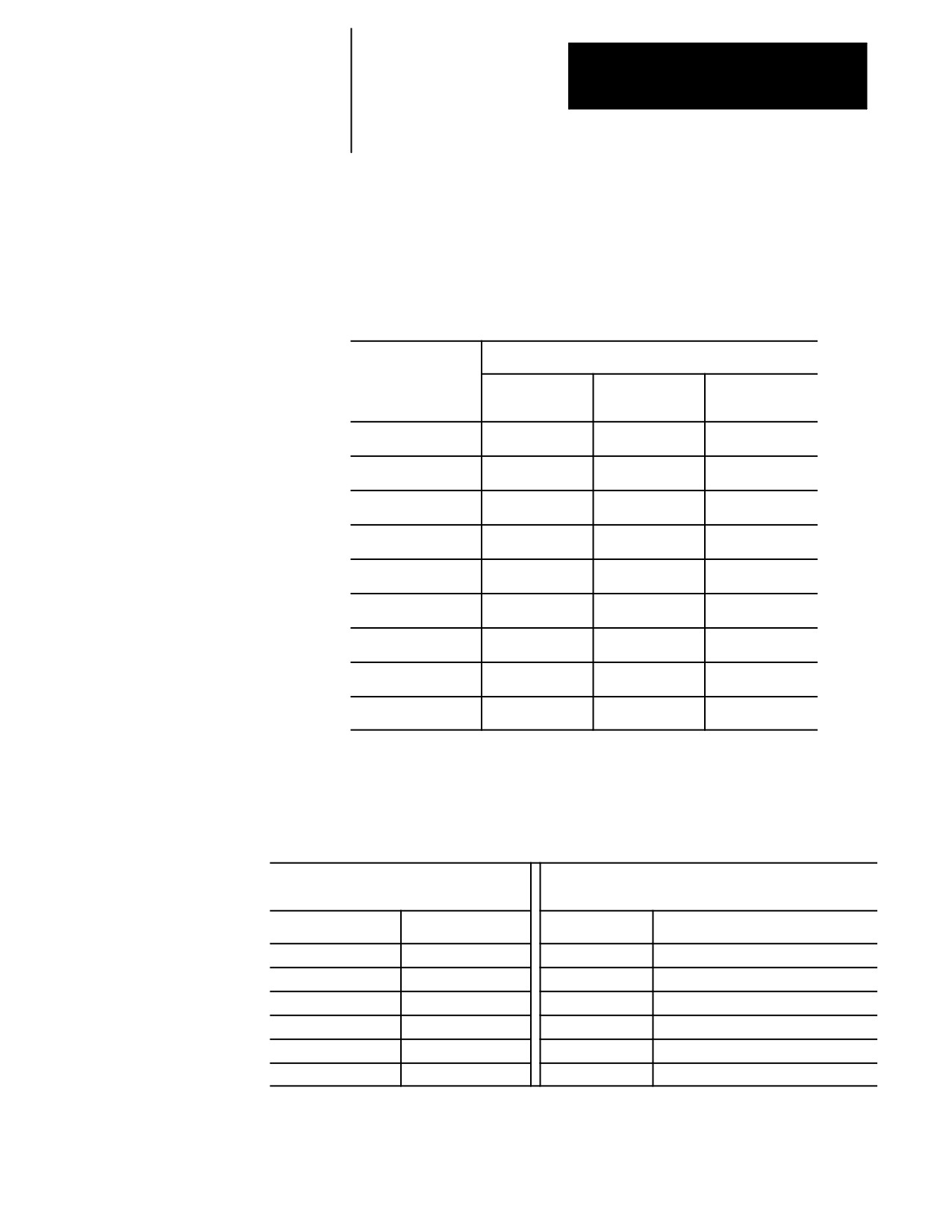
Table 10.A shows the effects of leading zero suppression (LZS) and
trailing zero suppression (TZS). It presumes that your system installer has
set a format of X5.2 (integer 5 digits, decimal 2 digits) in AMP. Different
formats would result in different decimal point placement compared to
those shown below, but the end result would be comparable.
Table 10.A
How the Control Interprets Numeric Values
Position Interpreted by the Control
Programmed X Value
TZS Disabled
TZS Disabled
TZS Enabled
LZS Disabled
LZS Enabled
LZS Disabled
X123456.
ERROR
ERROR
ERROR
X12345.6
12345.60
12345.60
12345.60
X1234.56
1234.56
1234.56
1234.56
X123.456
123.45
123.45
123.45
X12345
12345.00
123.45
12345.00
X012345
ERROR
123.45
1234.50
X123456
ERROR
1234.56
12345.60
X1234567
ERROR
12345.67
12345.67
X12345678
ERROR
ERROR
ERROR
Using LZS and TZS with G-Codes
The following table illustrates how the control interprets different G-Codes
in leading zero and trailing zero suppression modes.
Leading Zero Suppression Mode
Trailing Zero Suppression Mode
(decimal assumed at end if not programmed)
(2-digit G-code assumed unless decimal point programmed)
Program this:
Results in this:
Program this:
Results in this:
G02
2
G02
2
G2
2
G2
20
G2.
2
G2.
2
G92
92
G92
92
G920
920
G920
920 or 92 (if no AMP defined macro 920)
G92.1
92.1
G92.1
92.1
10-17
Chapter 10
Introduction to Programming
Important: If backing up a table using a G10 program (such as the offset
tables or coordinate system tables), keep in mind the G10 program output
is generated in the current format of the control (LZS or TZS). If you
intend to transport this table to a different machine it must also be using the
same format.
10.4.2
Your system installer can also set an AMP parameter to generate an error
or use a value of zero for characters that are programmed without numeric
Programming without
values. If this AMP feature is disabled, programming:
Numeric Values
GX;
rapid move to X zero (control assumes G00 X0;)
M;
program stop (control assumes M00)
would result in the actions described in the comments following the blocks.
If the feature is enabled, the error “NUMERIC MISSING” would have
occurred upon execution of either of those blocks.
10.4.3
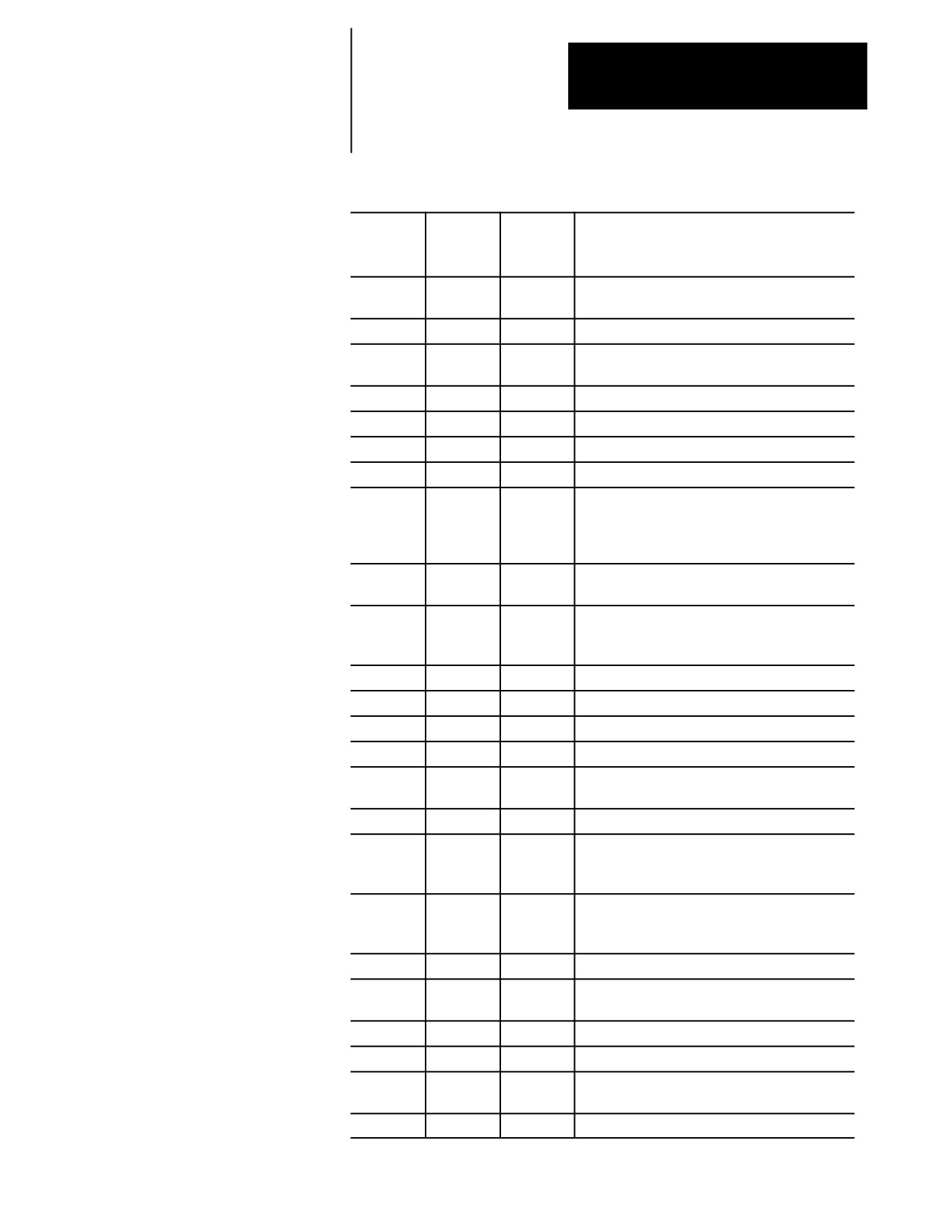
Table 10.B shows, in alphabetical order, the addresses for words that are
Word Descriptions and
recognized by the control, their typical formats, and their general
meanings. Since most of these formats are configured in AMP, refer to the
Ranges
documentation prepared by your system installer.
Many of the addresses can be altered in AMP. This table assumes the most
common names (such as X and Z for the main axes). Alterable addresses
are indicated by the note “AMP assigned.”
Later sections discuss these words in more detail, including variations in
their meanings when they are associated with certain G-codes. All words
discussed in this manual assume that the format and addresses in the
following table have not been changed by your system installer.
Important: The formats in this table indicate the maximum number of
digits left and the maximum number of digits right of the decimal point for
each word. In many cases, they are not valid together since the control
allows a maximum of 8 total digits. Refer to your system installer’s
manual for specific formats.
10-18
Chapter 10
Introduction to Programming
Table 10.B
Word Formats and Descriptions
Address
Valid
Valid
Function
Range
Range
inch
metric
A
8.6
8.5
Rotary axis about X (AMP assigned)
3.3
3.3
Angle in QuickPath Plus programming
B
3.0
3.0
Second miscellaneous function (AMP assigned)
C
8.6
8.5
Rotary axis about Z (AMP assigned)
8.6
8.5
Chamfer length in QuickPath Plus programming
D
8.6
8.5
Fixed cycle parameter
E
2.6
3.7
Thread lead
F
8.6
8.5
Feedrate function (F-word)
G
2.1
2.1
Preparatory function (G-code)
I
8.6
8.5
X arc center in circular interpolation
8.6
8.5
X lead in helical interpolation
8.6
8.5
Parameter in fixed cycles (AMP assigned)
8.6
8.5
Exit move vector in cutter compensation
J
8.6
8.5
Parameter in fixed cycles (AMP assigned)
8.6
8.5
Exit move vector in cutter compensation
K
8.6
8.5
Z arc center in circular interpolation
8.6
8.5
Parameter in fixed cycles (AMP assigned)
8.6
8.5
Exit move vector in cutter compensation
L
3.0
3.0
Number of repetitions
M
3.0
3.0
Miscellaneous function
N
5.0
5.0
Sequence number
O
5.0
5.0
Program name
P
5.0
5.0
Subprogram name
5.3
5.3
Length of dwell in G04 and fixed cycles
Q
8.6
8.5
Parameter in fixed cycles
R
8.6
8.5
Arc radius
8.6
8.5
Return point in fixed cycles
8.6
8.5
QuickPath Plus radius designation
S
5.3
5.3
Spindle rpm function
3.3
3.3
Spindle Orient
4.3
3.3
CSS
T
6.0
6.0
Tool selection function
U
8.6
8.5
Incremental axis name (Lathe A only)
5.3
5.3
Length of dwell in G04 and fixed cycles
V
8.6
8.5
Incremental axis name (Lathe A only)
W
8.6
8.5
Incremental axis name (Lathe A only)
X
8.6
8.5
Main axis (AMP assigned)
5.3
5.3
Length of dwell in G04
Z
8.6
8.5
Main axis (AMP assigned)
10-19
Chapter 10
Introduction to Programming
10.4.4
The maximum programmable value accepted by the control is 99,999,999.
The minimum is .000001 inch or .00001mm. The actual range of
Minimum and Maximum
programmable values depends on specifications determined by your
Axis Motion (Programming
system installer.
Resolution)
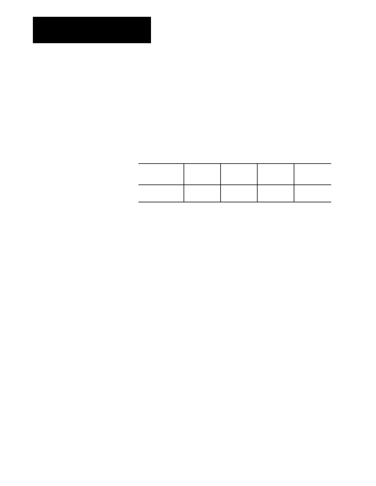
By using AMP to establish the format of numeric values for words, your
system installer sets the “programming resolution” for axis motion, the
smallest programmable distance of axis motion.
Table 10.C
Programming Resolutions
Formats as set in
_.3
_.4
_.5
_.6
AMP
Corresponding
0.001
0.0001
0.00001
0.000001
Resolution
Refer to your system installer’s documentation for the programming
resolutions and ranges in a specific system.
10.5
This section describes general features of the words used in programming.
Word Descriptions
Later chapters in this manual describe how to use these words in detail.
10.5.1
Axis words are made up of an axis name followed by the desired numeric
value for that word.
Axis Names
For axis names, the system installer chooses from:
A B C U V W X Y Z $X $Y $Z $B $C
These are assigned in AMP. This manual assumes primary axes one, two,
and three to be labeled X, Y, and Z respectively. Integrand words for these
axes are assumed by be I, J, and K respectively. Incremental or parallel
axis names for these axes are assumed to be U, V, W, respectively.
10-20
Chapter 10
Introduction to Programming
10.5.2
To simplify programming an angle, corner radius, or chamfer between two
lines, all that is necessary is the angle between the lines and the radius or
A_L_,R_,C_ (QuickPath Plus
chamfer size connecting them. This method of programming can be used
Words)
to simplify the cutting of many complex parts.
QuickPath words are made up of the addresses below followed by the
desired numeric value.
If you see:
It means:
,A
angle
L
length
,R
corner radius
,C
chamfer size
Important: A comma “,” must precede the ,R and ,C address characters
for the control to recognize them as radius or chamfer words.
For more details and examples using these words, see chapters 16 and 17.
10.5.3
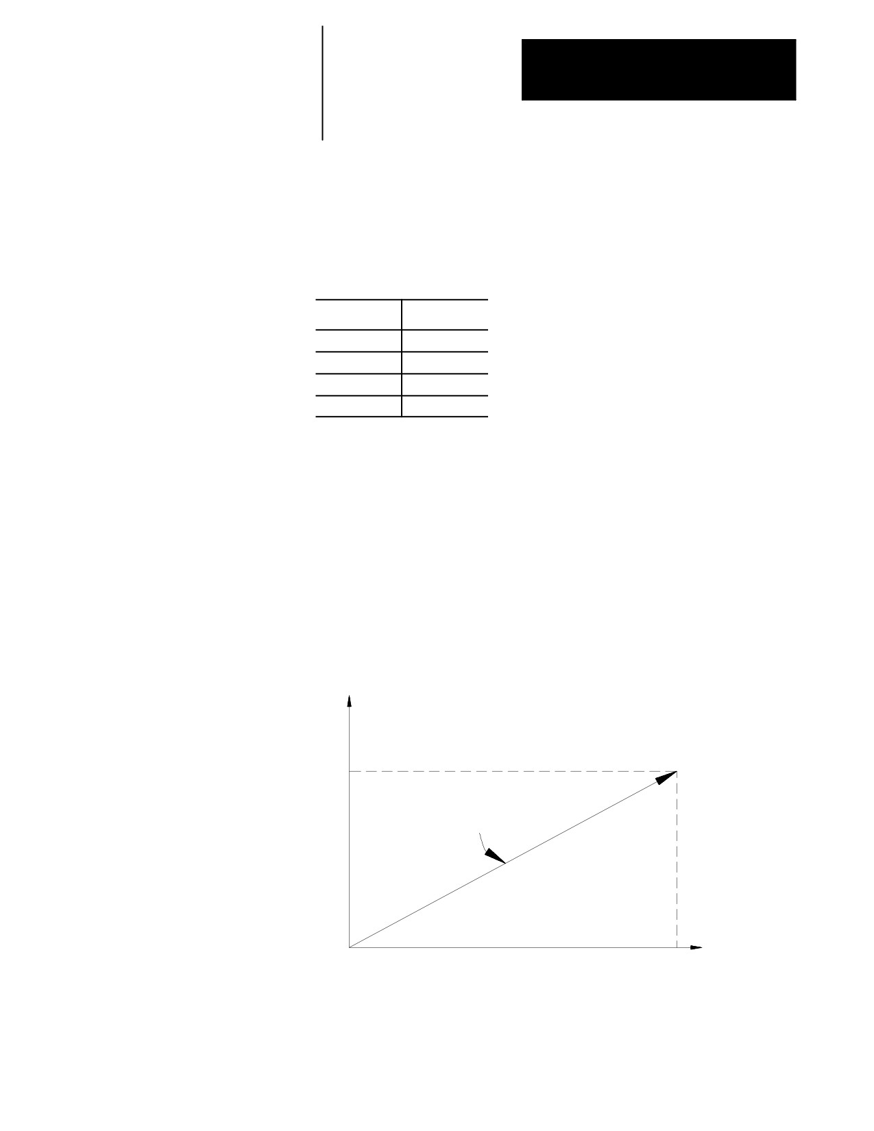
An F-word with numeric values specifies feedrates for the cutting tool in
linear interpolation (G01), and circular interpolation (G02/G03) modes.
F-Words (Feedrate)
The feedrate is the speed along a vector of the commanded axes, as shown
in Figure 10.5.
Figure 10.5
Feedrate Vectors
Y
55
end point
Feedrate of 220 is effective
along this motion path
X
start point
75
The term “feed” refers to moving a tool at a specific velocity in a cutting
path.
“Feedrate” is the velocity programmed for the feed of a tool.
10-21

Chapter 10
Introduction to Programming
Feedrates are expressed by the distance of movement per interval.
Depending on the mode of the control and the results you want, the
distance can be millimeters, inches, meters, or revolutions. The interval
can be minutes or revolutions.
Table 10.D
Feedrate Units
Unit/Interval
Abbreviation
Typically Used For:
millimeters per minute
mmpm
linear axis feedrates
inches per minute
ipm
linear axis feedrates
revolutions per minute
rpm
rotary axis feedrates
millimeters per rev
mmpr
threading
inches per rev
ipr
threading
In a metric part program for a linear axis, a feedrate of 100 millimeters per
minute (mmpm) typically would be written as F100.; (depending on the
active word format).
For details on programming feedrates by using the different feedrate
modes, see chapter 18. It also describes special preassigned feedrates.
Important: Feedrates programmed in any of the feedrate modes (G94 or
G95) can be overridden by use of the <FEEDRATE OVERRIDE> switch.
10.5.4
The preparatory function is designated by a G-code consisting of address G
G-Codes (Preparatory
followed by a two-digit value. In some cases, the G-code may have an
additional decimal digit. Because many of these are set by industry
Functions)
standards, they are usually referred to as G-codes. The G-codes are
classified as modal and non-modal.
Modal
the G-code remains in effect until another G-code in the same G-code group
is programmed.
Non-modal
the G-code is in effect only in the block in which it is programmed.
Important: When you program more than one G-code from the same
modal group in a block, the control executes the block as the G-codes
occur in the block sequentially from left to right. Any mode that is being
changed in a block only applies to the values to the right of the G-code.
Characters to the left of the G-code still use the old operating mode.
When the control executes an M02 or M30 code the system installer
determines in AMP if the modal M- and G-codes reset to their default
values. These default values become active at power up, E-STOP reset, or
control reset. Your system installer determines these defaults in AMP.
10-22

Chapter 10
Introduction to Programming
Important: G-codes can also be expressed in terms of a parametric
expression (for example G[#12+6]). For details, see chapter 28.
Example 10.8 explains execution of modal G-codes, using G00
and G01,
both classified into the same G-code group.
Example 10.8
Programming Modal G-codes
G00 X1. Z2.;
G00 mode is effective
Z3. ;
G00 mode is effective
G01 X2. Z1. ;
G01 mode is made effective
X3. Z3. ;
G01 mode is in effect
G00 X1.Z2. ;
G00 mode becomes effective again
G01 G00 Z3, ;
G00 mode is in effect
G01 G91 Z2 ;
G01 and G91 both in effect
Example 10.9 is an example of non-modal G-code execution.
Example 10.9
Programming Non-modal G-codes
G00 X1. Z21 ;
G00 mode is effective
G28 X2.;
G28 mode, this block only
X2. Z1. ;
G00 mode is effective
G04 P2. X4. ;
G04 active followed by move in G00
Example 10.10
Changing Modes Mid-block
N10G90X10G91Y10;
X10 is absolute (G90) Y10 is incremental (G91).
N20X20;
X20 is incremental (G91).
N30X30G90Y10;
X30 is incremental (G91), Y10 is absolute (G90).
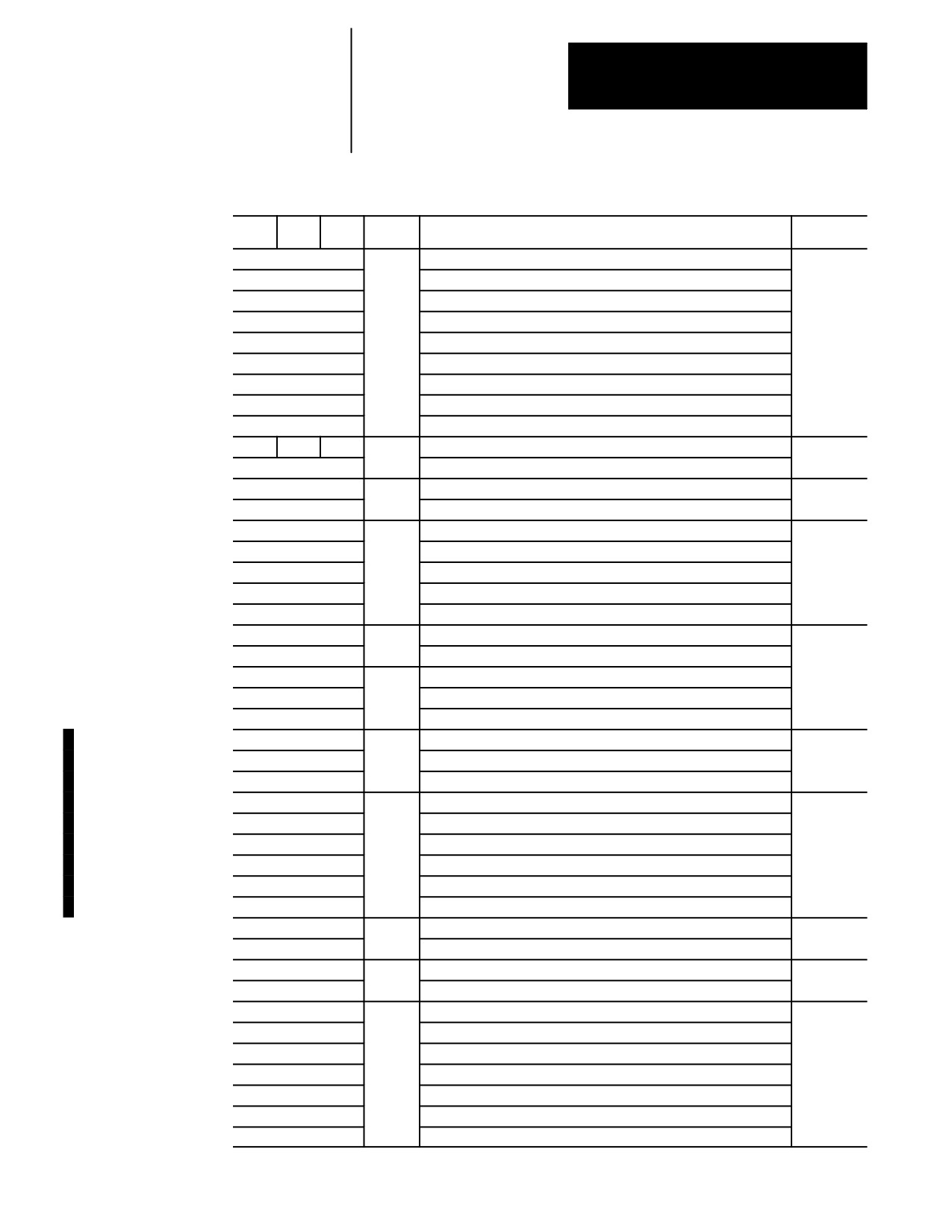
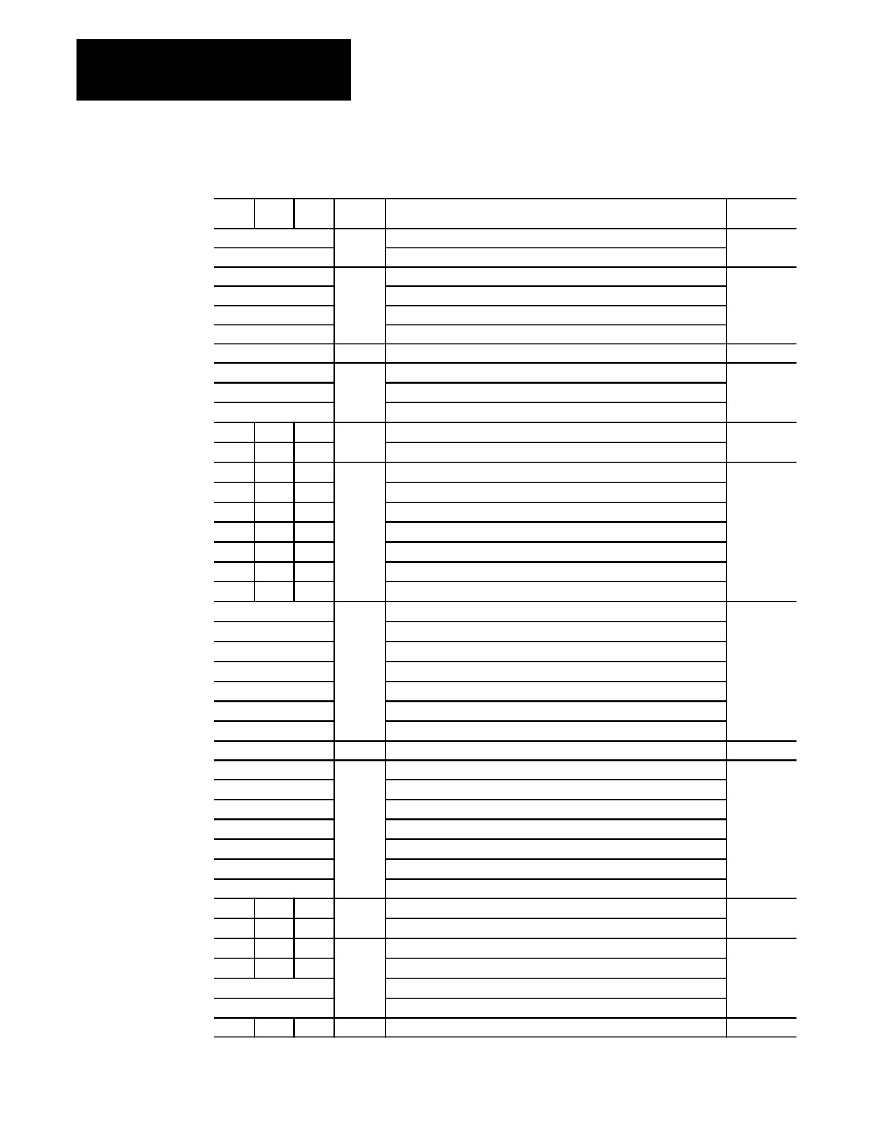
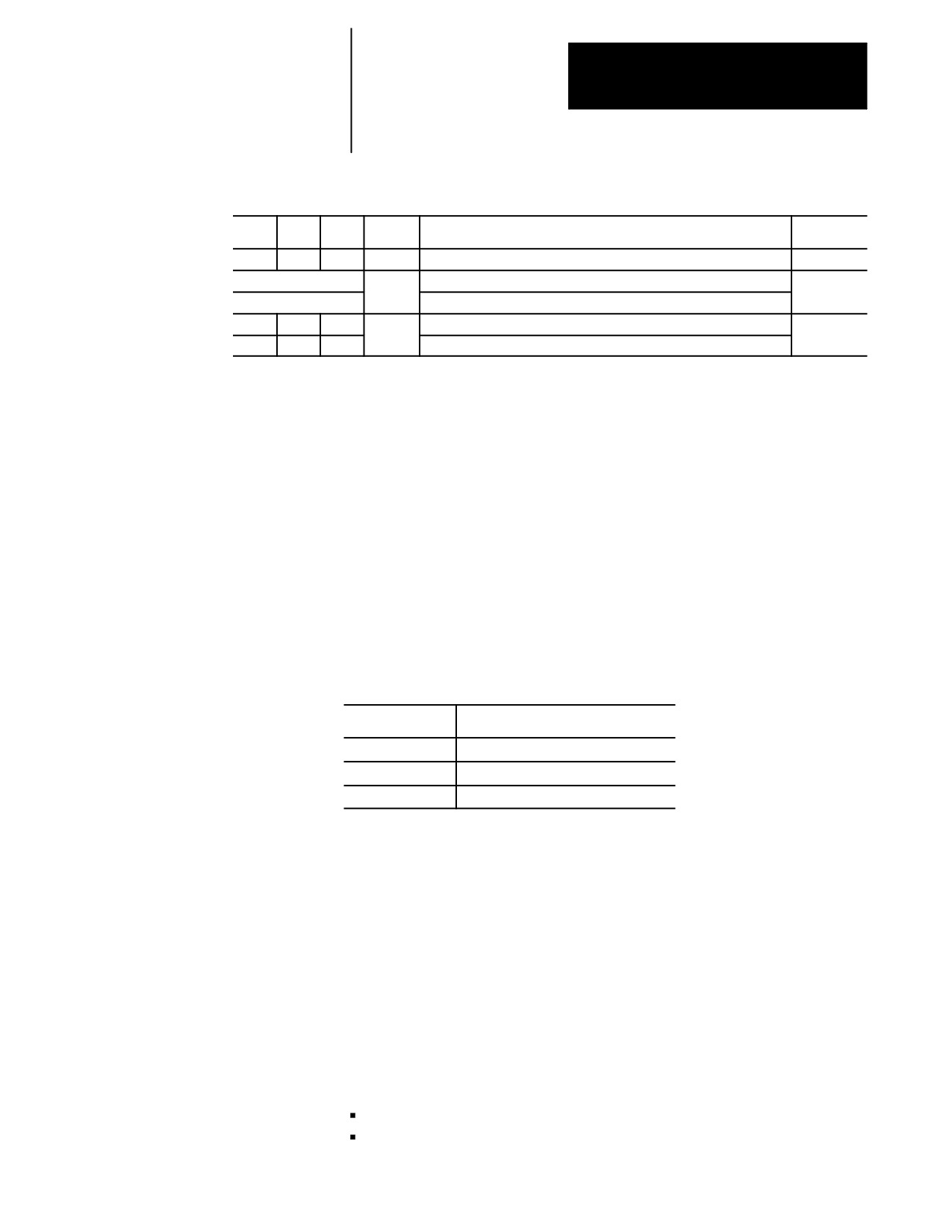
Table 10.E breaks down the G-codes into their modal groups. For
example, G-codes in group 01 are modal only with other G-codes in group
01. G-codes in the 00 group are non-modal, and they are effective only in
the block in which they are programmed.
The 9/Series control provides 3 G-code systems. They are systems A, B,
and C. Your system installer determines which G-code system is used for
a specific application in AMP.
Important: This manual makes the assumption that G-code system C is
used.
10-23
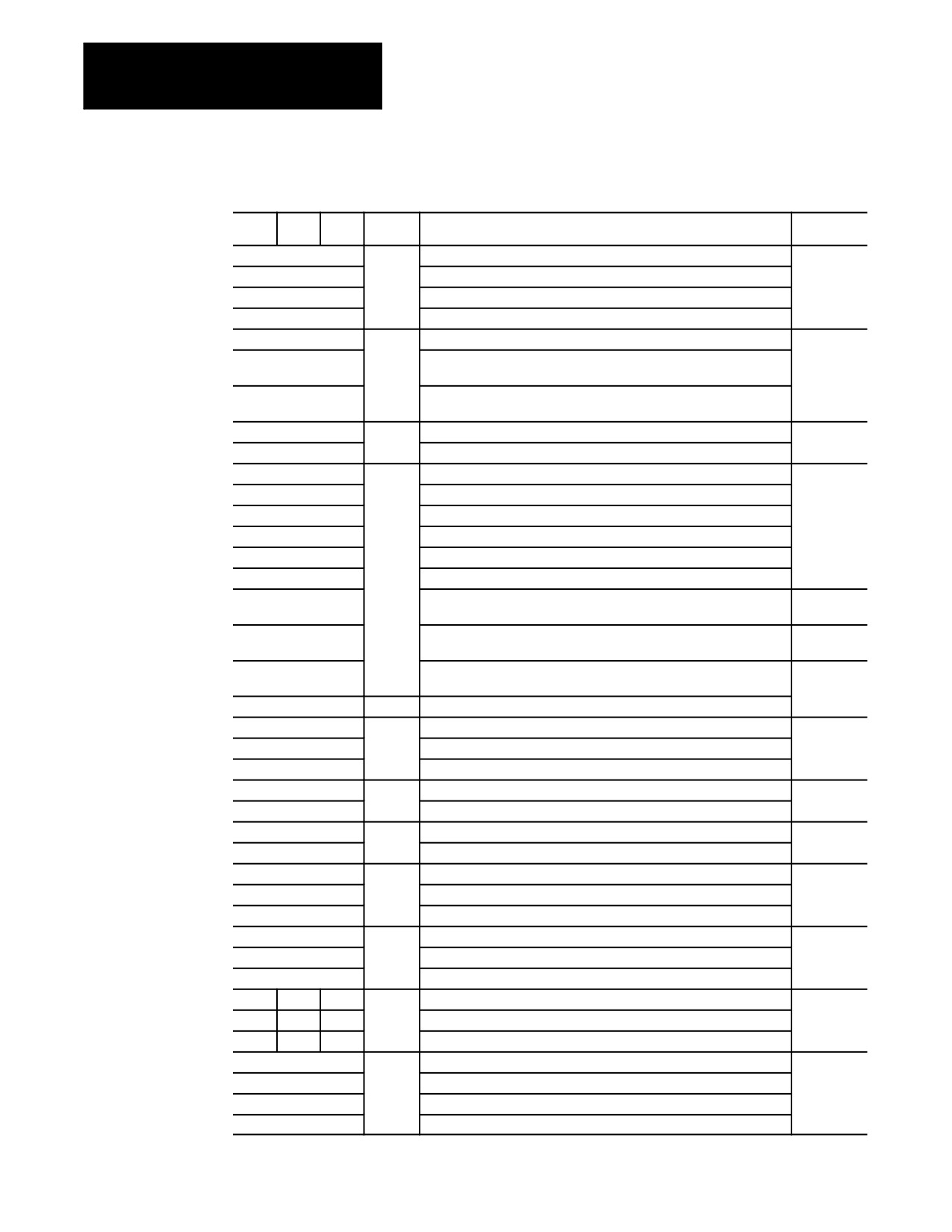
Chapter 10
Introduction to Programming
Table 10.E
G-code Table
A
B
C
Modal
Function
Type
G00
01
Rapid Positioning
Modal
G01
Linear Interpolation
G02
Circular Interpolation (Clockwise)
G03
Circular Interpolation (Counterclockwise)
G04
00
Dwell
Non-Modal
G05
Send Command and Wait for Return Status
(used with 9/Series Data Highway Plus Communication Module)
G05.1-G05.4
Send Command without Waiting for Return Status
(used with 9/Series Data Highway Plus Communication Module)
G07
18
Programming Using Radius Values
Modal
G08
Programming Using Diameter Values
G09
00
Exact Stop
Non-Modal
G10L2
Setup Work Coordinate Offset Table
G10L3
Setup Tool Management Table
G10L10
Setup Tool Offset Values Geometry Table
G10L11
Setup Tool Offset Values Wear Table
G10.1
Setup Random Tool Table
G10.2L1
Communication Configuration Table
(used with 9/Series Data Highway Plus Communication Module)
G10.2L2
Output Command Table
(used with 9/Series Data Highway Plus Communication Module)
G10.2L3
Download Configuration Information
(used with 9/Series Data Highway Plus Communication Module)
G11
Setup Tool Management Table (Cancel)
G12.1
21
Spindle 1 Controlling
Modal
G12.2
Spindle 2 Controlling
G12.3
Spindle 3 Controlling
G13
00
QuickPath Plus (Use First Intersect.)
Non-Modal
G13.1
QuickPath Plus (Use Second Intersect.)
G14
19
Scaling (Disable)
Modal
G14.1
Scaling (Enable)
G15
15
Virtual C (Cancel)
Modal
G16.1
Virtual C Cylindrical Interpolation
G16.2
Virtual C End Face Milling
G17
02
Plane Selection
Modal
G18
Plane Selection
G19
Plane Selection
G90
G77
G20
01
Single Pass O.D. and I.D. Roughing
Modal
G92
G78
G21
Single Pass Thread Cycle
G94
G79
G24
Single Pass Rough Facing Cycle
G22
04
Programmable Zone 2 and 3 (On)
Modal
G22.1
Programmable Zone 3 (On)
G23
Programmable Zone 2 and 3 (Off)
G23.1
Programmable Zone (Off)
10-24
Chapter 10
Introduction to Programming
Table 10.E (continued)
G-code Table
A
B
C
Modal
Function
Type
G27
00
Machine Home Return Check
Non-Modal
G28
Automatic Return to Machine Home
G29
Automatic Return from Machine Home
G30
Return to Secondary home
G31
External Skip Function 1
G31.1
External Skip Function 1
G31.2
External Skip Function 2
G31.3
External Skip Function 3
G31.4
External Skip Function 4
G32
G33
G33
01
Constant Lead Thread Cutting
Modal
G34
Variable Lead Thread Cutting
G36
22
Short Block Acc/Dec (Enable)
Modal
G36.1
Short Block Acc/Dec (Disable)
G37
00
Tool Gauging Skip Function 1
Non-Modal
G37.1
Tool Gauging Skip Function 1
G37.2
Tool Gauging Skip Function 2
G37.3
Tool Gauging Skip Function 3
G37.4
Tool Gauging Skip Function 4
G39
20
Tool Tip Radius Compensation (Linear Generated Block)
Modal
G39.1
Tool Tip Radius Compensation (Circular Generated Block)
G40
07
Tool Tip Radius Compensation (Cancel)
G41
Tool Tip Radius Compensation (Left)
G42
Tool Tip Radius Compensation (Right)
G47
24
Linear Acc/Dec in All Modes
Modal
G47.1
S--Curve Acc/Dec for Positioning and Exact Stop Mode
G47.9
Infinite Acc/Dec (No Acc/Dec) (Amp--selectable only)
G48
00
Reset Acc/Dec to Default AMP’d Values
Non--Modal
G48.1
Acceleration Ramp for Linear Acc/Dec Mode
G48.2
Deceleration Ramp for Linear Acc/Dec Mode
G48.3
Acceleration Ramp for S--Curve Acc/Dec Mode
G48.4
Deceleration Ramp for S--Curve Acc/Dec Mode
G48.5
Programmable Jerk Value
G50.1
11
Programmable Mirror Image (Cancel)
Modal
G51.1
Programmable Mirror Image
G52
00
Offset Coordinate Zero Points
Non-Modal
G53
Motion in Machine Coordinate System
G54
12
Preset Work Coordinate System 1
Modal
G55
Preset Work Coordinate System 2
G56
Preset Work Coordinate System 3
Modal
G57
Preset Work Coordinate System 4
G58
Preset Work Coordinate System 5
G59
Preset Work Coordinate System 6
G59.1
Preset Work Coordinate System 7
10-25
Chapter 10
Introduction to Programming
Table 10.E (continued)
G-code Table
A
B
C
Modal
Function
Type
G59.2
Preset Work Coordinate System 8
G59.3
Preset Work Coordinate System 9
G61
13
Exact Stop Mode
Modal
G62
Automatic Corner Override
G63
Tapping Mode
G64
Cutting Mode
G65
00
Paramacro Call
Non-Modal
G66
14
Paramacro call
Modal
G66.1
Paramacro call
G67
Paramacro call cancel
G20
G20
G70
06
Inch system selection
Modal
G21
G21
G71
Metric system selection
G70
G70
G72
00
O.D. and I.D. Finishing Cycle
Non-modal
G71
G71
G73
O.D. and I.D. Roughing Cycle
G72
G72
G74
Rough facing cycle
G73
G73
G75
Casting/forging roughing cycle
G74
G74
G76
Face Grooving Cycle
G75
G75
G77
O.D. and I.D. Grooving Cycle
G76
G76
G78
O.D. and I.D. Multi-Pass Threading Routine
G80
09
Cancel or end fixed cycle
Modal
G81
Drilling cycle (no dwell, rapid out)
G82
Drilling cycle (dwell, rapid out)
G83
Deep hole peck drilling cycle
G83.1
Deep hole peck drilling cycle (dwell)
G84
Right hand tapping cycle
G84.1
Left hand tapping cycle
G84.2
Right hand solid tapping cycle
G84.3
Left hand solid tapping cycle
G85
Boring cycle (no dwell, feed out)
G86
Boring cycle (spindle stop, rapid out)
G86.1
Boring cycle (spindle shift)
G87
Back boring cycle
G88
Boring cycle (spindle stop, manual out)
G89
Boring cycle (dwell, feed out)
-- --
G90
G90
03
Absolute mode
Modal
-- --
G91
G91
Incremental mode
G50
G92
G92
00
Coordinate offset using tool positions
Non-modal
G50
G92
G92
Maximum CSS Spindle RPM
G92.1
Coordinate system offset cancel
G92.2
Cancel select offsets
G98
G94
G94
05
Feed per minute mode
Modal
10-26
Chapter 10
Introduction to Programming
Table 10.E (continued)
G-code Table
A
B
C
Modal
Function
Type
G99
G95
G95
Feed per revolution mode
G96
17
CSS ON
Modal
G97
RPM Spindle Speed Mode
-- --
G98
G98
10
Initial level return drilling cycles
Modal
-- --
G99
G99
R-point level return drilling cycles
A set of default G-codes becomes effective at power up, when the control
is reset,or an emergency stop condition is reset. These default G-codes are
selected by your system installer in AMP. These default G-codes can be
seen on the status display screen after power up or control reset.
10.5.5
This section describes the axis integrand words. Integrand words define
parameters that relate to a specific axis for a canned cycle, probing cycle,
I J K Integrand Words
or circular motion block, but they are not limited to these operations. For
example, in circular motion blocks the axis integrands are used to define
the center point of the arc being cut.
Your system installer has the option of assigning either I, J, K, or none as
the axis integrand name for a specific axis. This manual makes the
following assumption:
Integrand Name:
Axis:
K
integrand name for the Z axis
I
integrand name for the X axis
J
integrand name for the C axis
Important: Refer to your system installers documentation to make sure
the assumptions are true. If this assumption is not true, it is all examples
and formats in this manual that use a I, J, or K need to have their letters
replaced with your system installers integrand words accordingly.
10.5.6
The miscellaneous function is designated with an address M followed by a
2- or 3-digit numeric value. Because many of these are set by industry
M-Codes (Miscellaneous
standards, they are usually referred to as M-codes.
Functions)
When a miscellaneous function is designated in a block containing axis
motion commands, the control’s PAL program determines whether the
M-codes:
execute at the same time as the axis motion
execute before the axis motion
10-27
Chapter 10
Introduction to Programming
execute after the axis motion is completed
This order of execution can also be altered by using the paramacro feature,
system parameter #3003. See chapter 28.
Your system installer determines in AMP if M- and G-codes get reset
every time the control executes an M02 or M30 end of program command.
If the control does reset M- and G-codes, modal M- and G-codes default
back to their power up condition, and non-modal M- and G-codes are reset
to their default values. If M- and G-codes do not reset, all modal M- and
G-codes remain at their present value and non-modal M- and G-codes
remain at their present values.
Table 10.F shows the basic M-codes for the 9/Series control. A part
program block can contain as many basic M-codes as you want. If you
program more than one M-code from any modal group in the same block,
the rightmost M-code in that block for that modal group is the active
M-code for the block.
Your system installer cam define additional M-codes in PAL. Up to 4
M-codes can be activated in any one block. If more than 4 are
programmed in any one block, the right most 4 in that block are activated.
Other M-codes in the block are ignored. Refer to documentation provided
by your system installer for details on non-basic M-codes and their
operation.
10-28

Chapter 10
Introduction to Programming
Table 10.F
M-codes
M-code
Modal or
Group
Function
Number
Non-modal
Number
M00
NM
4
Program stop
M01
NM
4
Optional program stop
M02
NM
4
Program end
M30
NM
4
Program end and reset (tape rewind)
PRIMARY SPINDLE
M03
M
7
Spindle positive rotation (cw)
M04
M
7
Spindle negative rotation (ccw)
M05
M
7
Spindle stop
M19
M
7
Spindle orient
SPINDLE 2
M03.2
M
11
Spindle positive rotation (cw)
M04.2
M
11
Spindle negative rotation (ccw)
M05.2
M
11
Spindle stop
M19.2
M
11
Spindle orient
SPINDLE 3
M03.3
M
12
Spindle positive rotation (cw)
M04.3
M
12
Spindle negative rotation (ccw)
M05.3
M
12
Spindle stop
M19.3
M
12
Spindle orient
M07
M
8
Mist coolant on
M08
M
8
Flood coolant on
M09
M
8
Coolant off
M48
M
9
Overrides enabled
M49
M
9
Overrides disabled
M58
M
10
CSS permit
M59
M
10
CSS prohibit
M98
NM
5
Sub-program call
M99
NM
5
Sub-program end and program jump
M100-M149
NM
13
Simple synchronization
M150-M199
NM
13
Synchronization with setup
10-29
Chapter 10
Introduction to Programming
(1) Program Stop (M00)
When you execute M00, execution stops after the block containing the
M00 is executed. At this time, the CRT displays the “PROG STOP”
message. To restart the operation, press the
<CYCLE START> button.
(2) Optional Program Stop (M01)
The optional program stop function has the same effect as the program stop
function, except that it is controlled by an external switch. When the
OPTIONAL PROGRAM STOP switch is placed in the OFF position, the
M01 code in the program is ignored. This switch and the appropriate PAL
programming are the responsibility of your system installer.
(3) End of Program (M02)
If you execute a program from control memory, the M02 code acts the
same as an M30. Program execution stops and the control enters the cycle
stop state. The program is reset to the first block and a <CYCLE START>
begins part program execution over again. See M99 for auto cycle start.
If you execute a program from an external device (such as a tape reader),
when M02 is executed, program execution stops and the control enters the
cycle stop state. The M02 does not cause a tape rewind. The tape reader
must be rewound using some other method before program execution can
resume.
With some machines, the M02 code can also result in a spindle and coolant
supply stop. For details, refer to the instruction manual prepared by your
system installer.
(4) End of Program, Tape Rewind (M30)
If you execute a program from control memory, the M30 code acts the
same as an M02. Program execution stops and the control enters the cycle
stop state. The program is reset to the first block and a <CYCLE START>
begins part program execution again. See M99 for auto cycle start.
If you execute a program from an external device (such as a tape reader),
when M30 is executed, program execution stops and the tape is
automatically rewound to the beginning of the program just executed.
After the tape rewinds, the control enters the cycle stop state. A <CYCLE
START> begins part program execution again. See M99.
With some machines, the M30 code can also result in a spindle and coolant
supply stop. For details, refer to the instruction manual prepared by your
system installer.
10-30
Chapter 10
Introduction to Programming
(5) Overrides Enabled (M48)
When your execute M48, the feedrate override, rapid feedrate override,
and the spindle speed override functions become effective. These are
enabled on power up without requiring this M code to be executed. An
M48 cancels an M49 and your system installer can choose which is active
upon power-up.
(6) Overrides Disabled (M49)
Use the override cancel M--code (M49) to ignore any override set by the
operator on the MTB panel. When you ignore the override setting, the axis
feedrate, rapid feedrate, and the spindle speed override values are all set to
100 percent. An M49 cancels an M48 and your system installer can
choose which is active upon power-up. This override setting is ignored if
you are using programmed motion.
(7) Constant surface speed mode enable (M58)
M58 cancels M59 mode, and it allows the control to recognize
programmed G96 constant surface speed mode and S-words to be
specified. The spindle resumes the speed it was revolving at prior to the
designation of M59.
CAUTION: Restoring the constant surface speed mode might
cause the spindle speed to increase or decrease rapidly,
depending on the cutting tool position.
(8) Constant surface speed mode disabled (M59)
M59 cancels M58 and G96, making the constant surface speed mode
ineffective. The spindle continues to revolve at the speed it was at the
moment the M59 executed.
Z or the spindle speed can be directly designated using an S code.
(9) Subprogram call (M98)
When you execute M98, a subprogram is called and executed. This word
can be used in any program including an MDI program. For details on
programming an M98, see page 10-11.
10-31
Chapter 10
Introduction to Programming
(10) End of Subprogram or Main Program Auto Start (M99)
M99 End of Subprogram or Paramacro program
When you execute M99, subprogram execution is completed and
program execution returns to the calling program. This word is not
valid in an MDI command, but it can be contained in a subprogram
called by an MDI command. For details on programming an M99, see
page 10-11 or chapter 28.
M99 End of Main Program with Auto Start
If you execute a program from memory, an M99 as the last block in a
main program stops program execution at that location. The program is
reset to the first block and a <CYCLE START> automatically starts
program execution for you.
If you execute a program from an external device (such as a tape
reader), when M99 is executed, program execution stops and the tape is
automatically rewound to the beginning of the program just executed
and a <CYCLE START> automatically starts program execution for
you.
CAUTION: The M99 code is commonly used as the end of
program for fully automated systems that automatically load the
next part to be machined. This code requires that some PAL
interface be written that assures the part is fully loaded and
ready for machining before block execution is allowed to
restart. Failure to do so can cause injury to operators or damage
to equipment.
For these systems some PAL interface should be written to assure that
the part is fully loaded before program execution is restarted.
(11) Simple Synchronization (M100-M149)
M100 - M149 — Simple Synchronization (dual-process system only)
These M-codes are for simple synchronization. When executed, this set
of M-codes does not re-setup any program blocks that have already been
read into program lookahead. See page 30-7.
10-32