9/Series CNC Lathe. Operation and Programming Manual - page 8
Chapter
8
Display and Graphics
8.0
The first part of this chapter gives a description of the different data
displays available on the control. The second part gives a description of
Chapter Overview
the control’s graphics capabilities.
8.1
Pressing the [DISP SELECT] key displays the softkeys for selecting the
axis position data screens.
Selection of Axis Position
Data Display
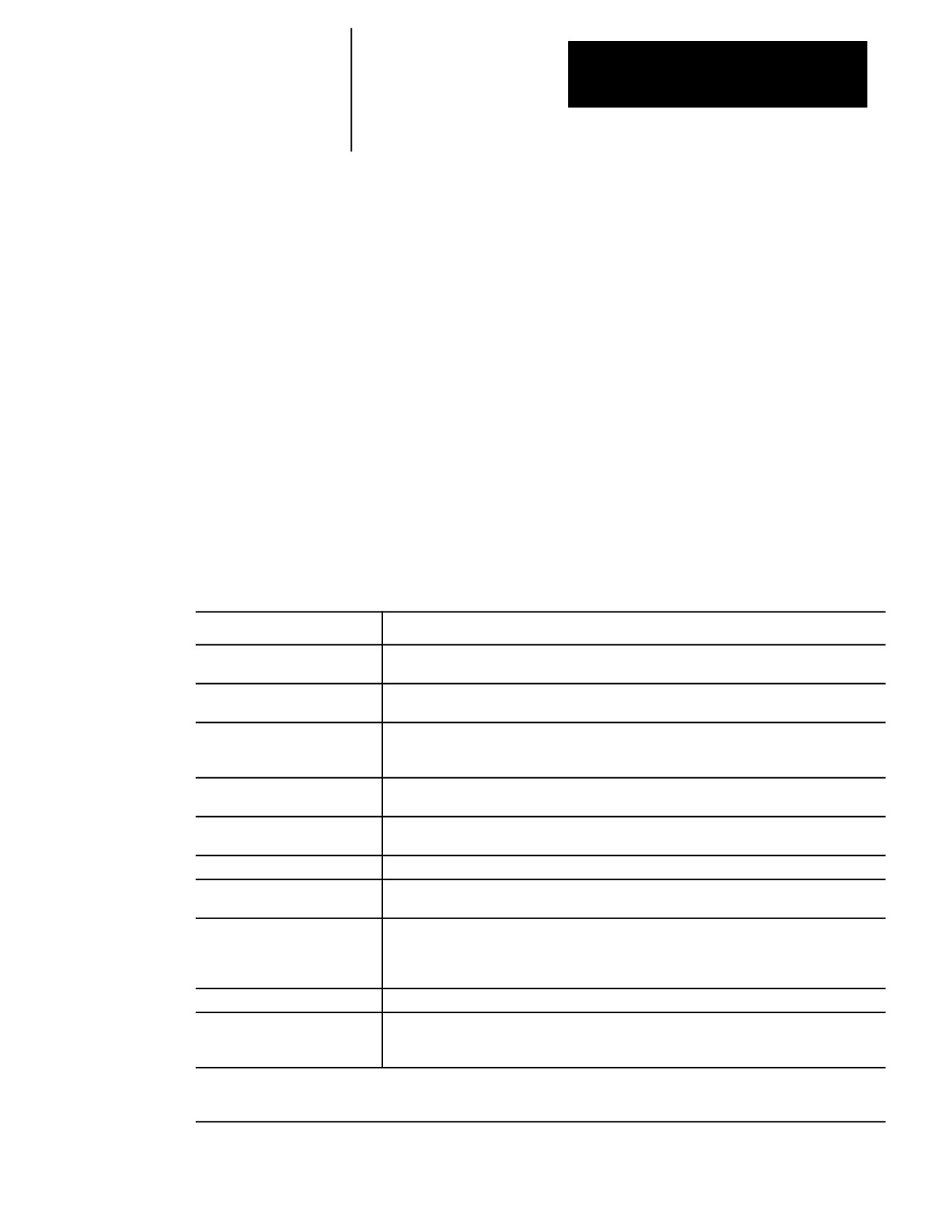
The control provides 8 different axes position data screens as described in
Table 8.A. Four of these screens may be displayed in normal (9 axis
maximum), large (4 axis triple size or 6 axis double size) or small (all axis
in process) characters if desired. Normal size is the default.
Table 8.A
Display Select Softkeys
Display
Description
{PRGRAM}
Axis position in the current work coordinate system is displayed. Each time this softkey is
pressed the display toggles between normal, large, and small1.
{ABS}
Axis position in the machine coordinate system is displayed. Each time this softkey is pressed
the display toggles between normal, large, and small1.
{TARGET}
Coordinate values, in the current work coordinate system, of the end point of commanded axis
motion is displayed. Each time this softkey is pressed the display toggles between normal,
large, and small1.
{DTG}
Distance from the current position to the end point of the commanded axis move displayed.
Distance to go
Each time this softkey is pressed the display toggles between normal, large, and small1.
{AXIS SELECT}
This softkey is used to select which axes are going to be displayed on normal (when more than
9 axes are available) and large displays. Small displays always show all system axes.
{M CODE STATUS}
M codes that are currently active are displayed.
{PROGRAM DTG}
This screen provides a multiple display of information from the program display screen and the
distance to go screen.
{All}
This screen provides a multiple display of position information program, target, absolute, and
distance to go screens. The all display is only available on systems with 6 or less axes. On
systems with more than 6 axes, other combination screens are available which display a subset
of the data available on the ALL display.
{G CODE STATUS}
G codes that are currently active are displayed.
{SPLIT SCREEN
If your system is AMPed for more than one process, you will have this additional softkey. It
ON/OFF}
allows you to view both processes at the same time. The active process appears in reverse
video. This selection remains for all future power up cycles or until you change it.
1 Small displays are only available when the system is configured to have more than 9 real axes or, for dual process systems, more
than 8 axes in a process. Virtual axes count as axes in your total. Adaptive depth probes configured as axes are not counted in this
total.
8-1
Chapter 8
Displays and Graphics
The screens described above may also show in addition to axis position:
The current unit system being used (millimeters or inches)
E-Stop
The current feedrate
The current spindle speed of the controlling spindle
The current tool and tool offset numbers
The active program name (if any)
The active subprogram name (if any)
The current operating mode (MDI, manual or automatic)
The current operating status (cycle stop, suspend, start, feedhold)
The current block executing (sequence number)
Up to four blocks of the current program selected for program execution
Subprogram paramacro 01 canned cycle repeat count executing
To select an axis position data display :
1.
Press the [DISP SELECT] key, to display the softkeys for selecting
axis position data screens. Press the [DISP SELECT] key at any time
from any softkey level. Pressing the page {Æ } softkey displays
additional selections.
Important: The [DISP SELECT] key is ignored if you are viewing the PAL
search monitor utility. You must select the screen to display before you
access PAL search monitor. Additionally you can not activate PAL search
monitor while viewing the Display Select options.
2.
Press the softkey corresponding to the display wanted. The softkeys
will toggle between large, small, and regular display mode each time
the corresponding softkey is pressed, provided that screen is available
as a large display.
The “large” and “small” display is available only for the axis position
screens (Program, Absolute, Target, and Distance to Go). Small
displays are only available when more than 9 axes are AMPed in a
system or, for dual process, more then 8 axes in a process.
For example, immediately after power up and accessing the
[DISP SELECT] feature, pressing the {DTG} softkey displays the
distance to go in normal size. Pressing it again changes the display
to show the distance to go in large character size.
The control can display any 4 axes in triple-height characters and any
6 axes in double-height characters. If you ask the control to display
more than 6 axes on a large display or 9 axis on a normal display, the
control displays the error message, “TOO MANY AXES
SELECTED FOR DISPLAY.” Small displays always show all axes
in the system in the active process.
8-2
Chapter 8
Displays and Graphics
3.
To return to softkey level 1, press the [DISP SELECT] key again. The
most recently selected data position screen will remain in effect for
softkey level 1 until either power is turned off or a different position
display screen is selected. The default screen selected at power up is
the regular size program display.
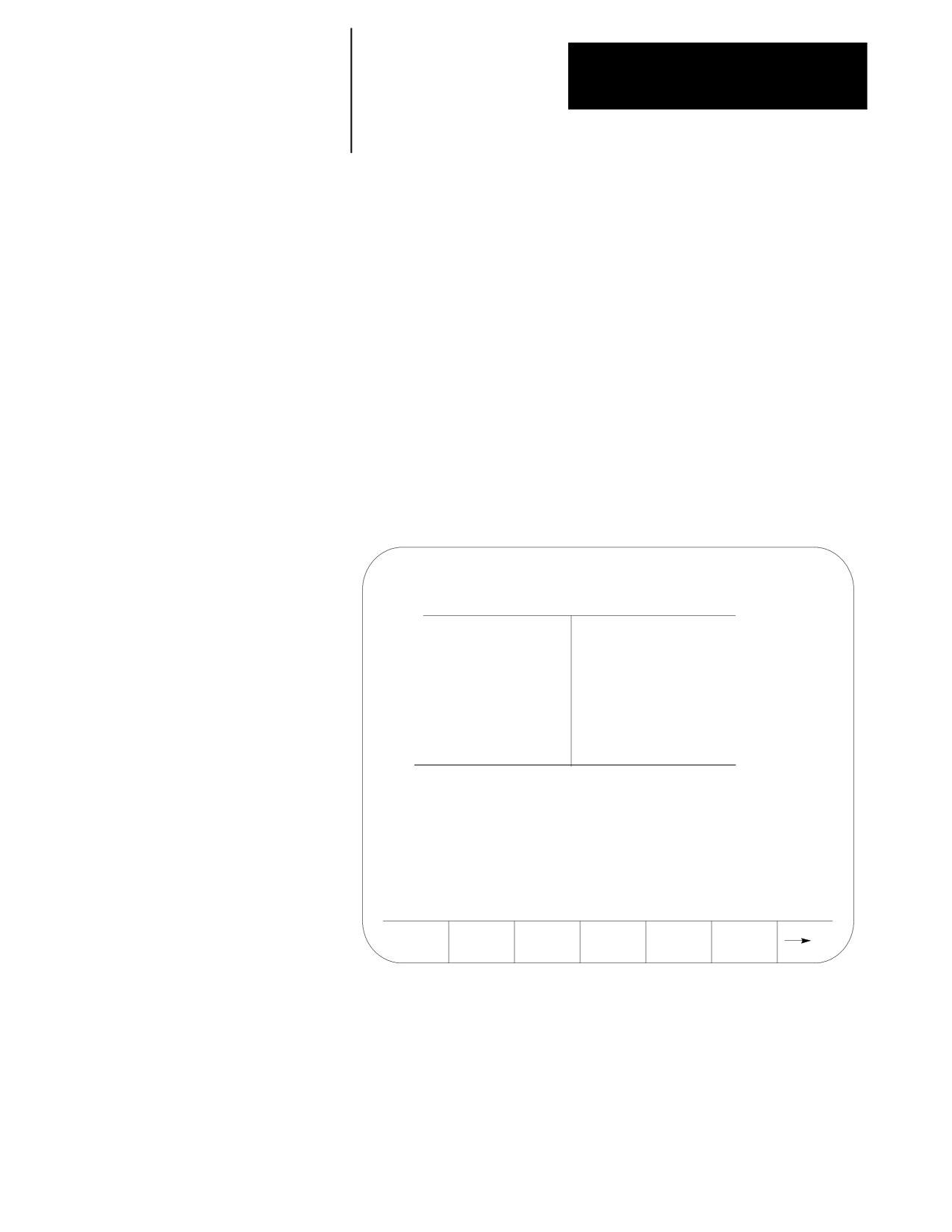
The following figures show the axis position data display that will result
when the corresponding softkey is pressed.
{PRGRAM}
Axis position in the current work coordinate system displayed in normal
size characters.
Figure 8.1
Result After Pressing {PRGRAM} Softkey
E-STOP
PROGRAM[ MM
]
F
0.000 MMPM
X
-7483.647
S
00
Z
-7483.647
T 0
U
-7483.647
(ACTIVE PROGRAM NAME)
MEMORY
MAN STOP
PRGRAM
A B S
TARGET
D T G
AXIS
SELECT
8-3
Chapter 8
Displays and Graphics
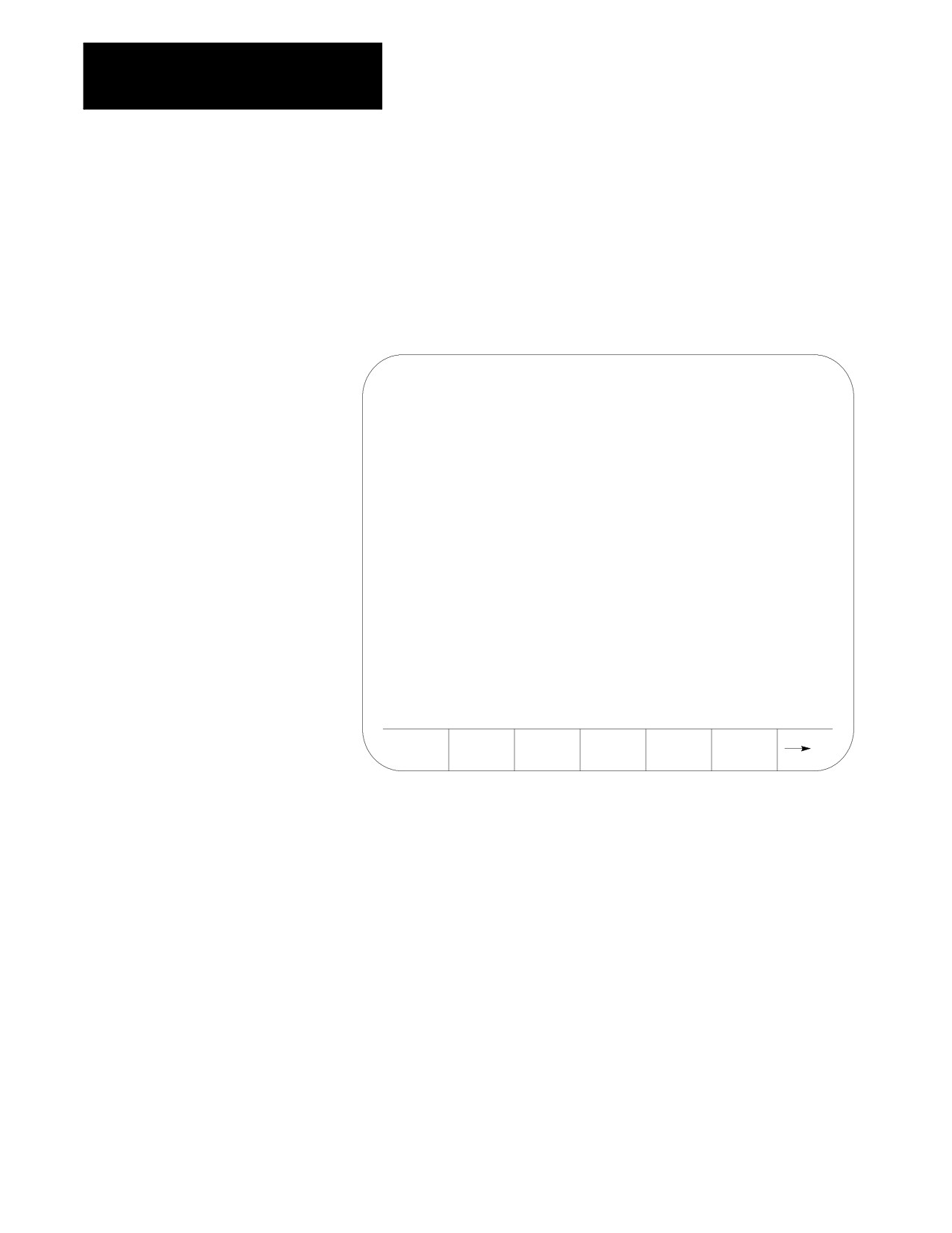
{PRGRAM} (Large Display)
Axis position in the current work coordinate system displayed in large
characters.
Figure 8.2
Results After Pressing {PRGRAM} (Large Display) Softkey
E-STOP
PROGRAM[ MM
]
(ACTIVE PROGRAM NAME)
X
-
7483 .647
Z
-
7483 .647
U
-
7483 .647
F
0.000 MMPM S
00
PRGRAM
A B S
TARGET
D T G
AXIS
SELECT
8-4
Chapter 8
Displays and Graphics
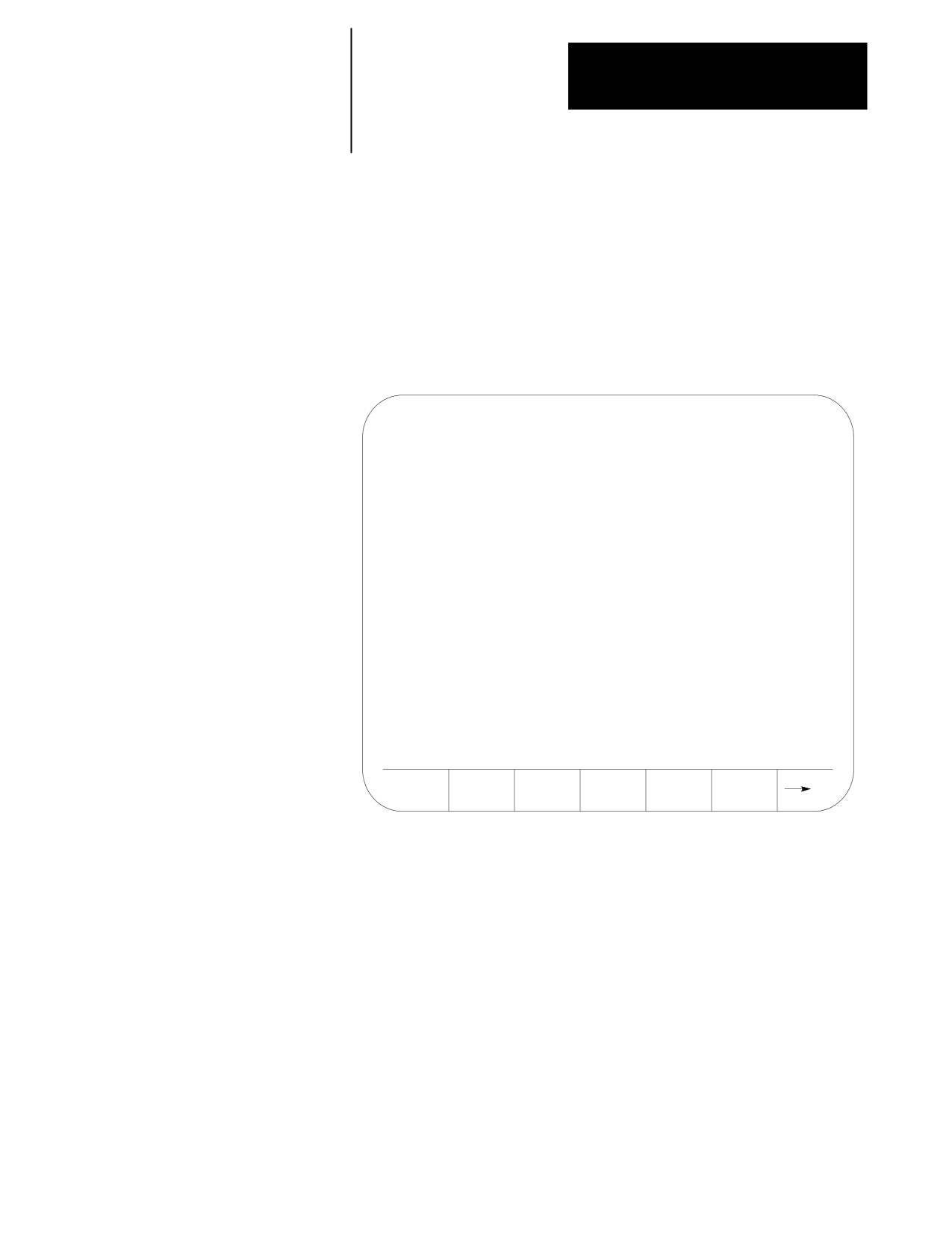
{PRGRAM} (Small Display)
Axis position in the current work coordinate system displayed for all
system axes in the active process (only available when more than 9 axis are
AMPed in the system, or more than 8 axis in the process for dual process
systems).
Figure 8.3
Results After Pressing {PRGRAM} (Small Display) Softkey
PROGRAM[ MM
]
X
-9999.647
Y
-3333.647
Z
-1111.647
U
-2222.647
V
-2222.647
W
-2222.647
A
-2222.647
B
-2222.647
C
-2222.647
$X -2222.647
$Y -2222.647
$Z -2222.647
F
0.000 MMPM
S
00
PRGRAM
A B S
TARGET
D T G
AXIS
SELECT
8-5

Chapter 8
Displays and Graphics
{ABS}
The axis position data in the machine coordinate system.
Figure 8.4
Results After Pressing {ABS} Softkey
E-STOP
ABSOLUTE[ MM
]
F
0.000 MMPM
X
0.000
S
00
Z
0.000
T 0
U
-0.035
(ACTIVE PROGRAM NAME)
MEMORY
MAN STOP
PRGRAM
A B S
TARGET
D T G
AXIS
SELECT
8-6
Chapter 8
Displays and Graphics
{ABS} (Large Display)
Axis position in the machine coordinate system displayed in large
characters.
Figure 8.5
Results After Pressing {ABS} (Large Display) Softkey
E-STOP
ABSOLUTE[ MM
]
(ACTIVE PROGRAM NAME)
X
0.000
Z
0.000
U
-0.035
F
0.000 MMPM S
00
PRGRAM
A B S
TARGET
D T G
AXIS
SELECT
{ABS} (Small Display)
The axis position data in the machine coordinate system displayed for all
system axes in the active process (only available when more than 9 axis are
AMPed in the system, or more than 8 axis in the process for dual process
systems).
8-7
Chapter 8
Displays and Graphics
Figure 8.6
Results After Pressing {ABS} (Small Display) Softkey
ABSOLUTE
[ MM
]
X
-9999.647
Y
-3333.647
Z
-1111.647
U
-2222.647
V
-2222.647
W
-2222.647
A
-2222.647
B
-2222.647
C
-2222.647
$X -2222.647
$Y -2222.647
$Z -2222.647
F
0.000 MMPM
S
00
PRGRAM
A B S
TARGET
D T G
AXIS
SELECT
8-8
Chapter 8
Displays and Graphics
{TARGET}
The coordinate values of the end point of the currently executing axis
move is displayed at a position in the current work coordinate system.
Figure 8.7
Results After Pressing {TARGET} Softkey
E-STOP
TARGET[ MM
]
F
0.000 MMPM
X -7483.647
S
00
Z -7483.647
T 0
U -7483.647
(ACTIVE PROGRAM NAME)
MEMORY
MAN STOP
PRGRAM
A B S
TARGET
D T G
AXIS
SELECT
8-9
Chapter 8
Displays and Graphics
{TARGET} (Large Display)
The coordinate values in the current work coordinate system, of the end
point of commanded axis moves in normal size characters.
Figure 8.8
Results after Pressing {TARGET} Softkey
E-STOP
TARGET [ MM
]
(ACTIVE PROGRAM NAME)
X
-
7483 . 647
Z
-
7483 . 647
U
-
7483 . 647
F
0.000 MMPM S
00
PRGRAM
A B S
TARGET
D T G
AXIS
SELECT
{TARGET} (Small Display)
The coordinate values of the end point of the currently executing axis
move is displayed at a position in the current work coordinate system for
all system axes in the active process (only available when more than 9 axis
are AMPed in the system, or more than 8 axis in the process for dual
process systems).
8-10
Chapter 8
Displays and Graphics
Figure 8.9
Results After Pressing {TARGET} (Small Display) Softkey
TARGET
[ MM
]
X
-9999.647
Y
-3333.647
Z
-1111.647
U
-2222.647
V
-2222.647
W
-2222.647
A
-2222.647
B
-2222.647
C
-2222.647
$X -2222.647
$Y -2222.647
$Z -2222.647
F
0.000 MMPM
S
00
PRGRAM
A B S
TARGET
D T G
AXIS
SELECT
8-11
Chapter 8
Displays and Graphics
{DTG}
The distance from the current position to the command end point, of the
commanded axis in normal size characters.
Figure 8.10
Results After Pressing {DTG} Softkey
E-STOP
DISTANCE TO GO[ MM
]
F
0.000 MMPM
X
0.021
S
00
Z
0.000
T 0
U
0.000
(ACTIVE PROGRAM NAME)
MEMORY
MAN STOP
PRGRAM
A B S
TARGET
D T G
AXIS
SELECT
8-12
Chapter 8
Displays and Graphics
{DTG} (Large Display)
The distance from current position to the command end point of the
commanded axis move in large characters.
Figure 8.11
Results After Pressing {DTG} (Large Display) Softkey
E-STOP
DISTANCE TO GO[ MM
]
(ACTIVE PROGRAM NAME)
X
0.021
Z
0.000
U
0.000
F
0.000 MMPM S
00
PRGRAM
A B S
TARGET
D T G
AXIS
SELECT
{DTG} (Small Display)
The distance from the current position to the command end point, of the
commanded axis in normal size characters is displayed for all system axes
in the active process (only available when more than 9 axis are AMPed in
the system, or more than 8 axis in the process for dual process systems).
8-13
Chapter 8
Displays and Graphics
Figure 8.12
Results After Pressing {DTG} (Small Display) Softkey
Distance to Go
[ MM
]
X
0000.000
Y
0000.000
Z
0000.000
U
0000.000
V
0000.000
W
0000.000
A
0000.000
B
0000.000
C
0000.000
$X 0000.000
$Y 0000.000
$Z 0000.000
F
0.000 MMPM
S
00
PRGRAM
A B S
TARGET
D T G
AXIS
SELECT
8-14
Chapter 8
Displays and Graphics
{AXIS SELECT}
Important: {AXIS SELECT} is available only during a large character
display or when more than 9 axes are displayed on a normal size display.
When you press {AXIS SELECT}, the control displays the axis names in the
softkey area. Press a specific axis letter softkey to toggle the position
display of that axis on and off.
If a normal size display is being viewed and the system has more than 9
axes, the axis select features can also select the axes for these normal size
displays. This feature has no affect on small displays. Small displays
always show all axes (only available on systems with more than 9 axes or
on dual process systems with more than 8 axes in a process).
Figure 8.13
Results After Pressing {AXIS SELECT} Softkey
E-STOP
DISTANCE TO GO[ MM
]
(ACTIVE PROGRAM NAME)
X
0.021
Z
0.000
U
0.000
F
0.000 MMPM S
00
AXIS
AXIS
AXIS
AXIS
AXIS
X
Z
U
W
V
8-15
Chapter 8
Displays and Graphics
{M CODE STATUS}
The currently active M--codes are displayed. This screen indicates only the
last programmed M--code in the modal group. It is the PAL programmers
responsibility to make sure proper machine action takes place when the
M--code is programmed.
Figure 8.14
Result After Pressing {M CODE} Softkey
M05
SPINDLE STOP
M09
COOLANT OFF
M48
FEEDRATE OVERRIDE ENABLE
M CODE
PRGRAM
ALL
D T G
8-16
Chapter 8
Displays and Graphics
{PRGRAM DTG}
This screen provides a multiple display of position information from the
program screen and the distance to go screen.
Figure 8.15
Program, Distance to Go Screen
E-STOP
PROGRAM
DISTANCE TO GO
[ MM ]
X
- 7483.647
X
0.031
Y
- 7483.647
Y
0.000
Z
- 7483.647
Z
0.000
F
0.000 MMPM
S
0
M CODE
PRGRAM
ALL
D T G
8-17
Chapter 8
Displays and Graphics
{PRGRAM DTG} (Small Display)
This screen provides a multiple display of position information from the
program screen and the distance to go screen. It displays all system axes in
the active process (only available when more than 9 axis are AMPed in the
system, or more than 8 axis in the process for dual process systems).
Figure 8.16
Program, Distance to Go Screen (Small Display)
PROGRAM
Distance to Go
[ MM
]
X
-9999.647
X
0000.000
Y
-3333.647
Y
0000.000
Z
-1111.647
Z
0000.000
U
-2222.647
U
0000.000
V
-2222.647
V
0000.000
W
-2222.647
W
0000.000
A
-2222.647
A
0000.000
B
-2222.647
B
0000.000
C
-2222.647
C
0000.000
$X -2222.647
$X 0000.000
$Y -2222.647
$Y 0000.000
$Z -2222.647
$Z 0000.000
F
0.000 MMPM
S
00
M CODE
PRGRAM
ALL
D T G
8-18
Chapter 8
Displays and Graphics
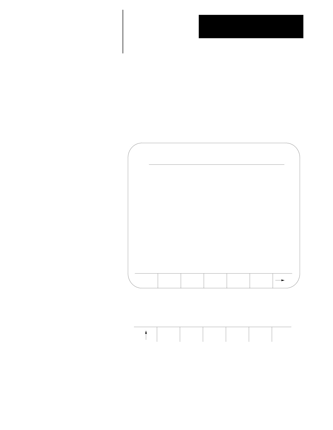
{ALL}
This screen provides a multiple display of position information from the
program, distance to go, absolute, and target screen. The all display is
only available on systems with 6 or less axes. On systems with more than
6 axes, other combination screens are available which display a subset of
the data available on the ALL display.
Figure 8.17
Result After Pressing {All} Softkey
E-STOP
PROGRAM
DISTANCE TO GO
[ MM ]
X
- 7483.647
X
0.000
Y
- 7483.647
Y
0.000
Z
- 7483.647
Z
0.000
ABSOLUTE
TARGET
X
0.000
X - 7483.647
Y
0.000
Y - 7483.647
Z
0.000
Z - 7483.647
U
0.000
U - 7483.647
F
0.000 MMPM
S
0
M CODE
PRGRAM
ALL
G CODE
D T G
STATUS
The {All} selection is not available for more than 6 axes.
Important: If you have more than 6 axes, then you will not have an {All}
softkey. A {PRG TAR} and a {PRG ABS} softkey appear.
M CODE
PRGRAM
PRG
PRG
G CODE
STATUS
D T G
TAR
ABS
STATUS
8-19
Chapter 8
Displays and Graphics
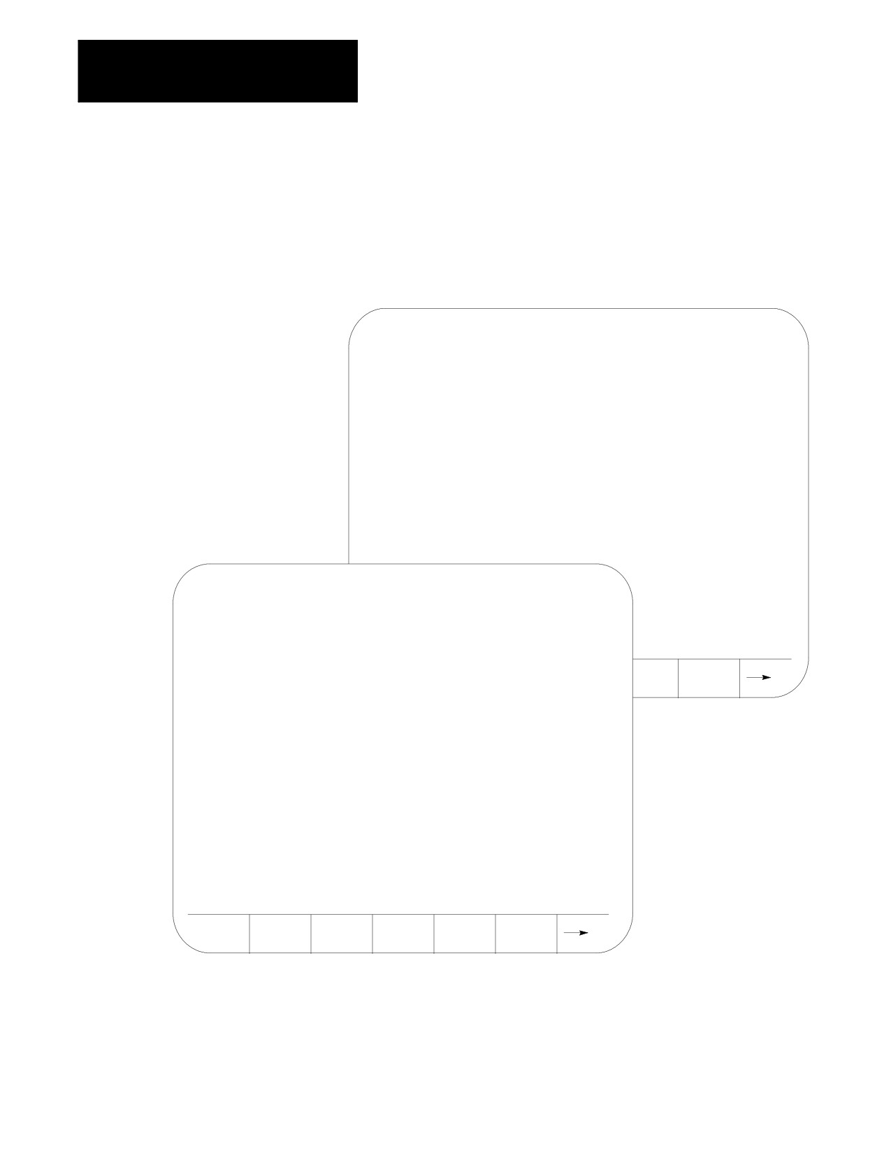
{G CODE STATUS}
The currently active G-codes are displayed.
Figure 8.18
Results After Pressing {G CODE} Softkey
PROGRAM STATUS
PAGE 2 OF 2
G50.1
MIRROR IMAGE CONTROL
G64
CUTTING MODE
G67
MACRO CALL CANCEL
G70
INCH PROGRAMMING
G80
CANCEL OR END FIXED CYCLE
G90
ABSOLUTE
G94
FEED/MIN
G97
CSS PROGRAMMING OFF
G98
FIXED CYCLE INITIAL LEVEL RETURN
PROGRAM STATUS
PAGE 1 OF 2
G01
LINEAR INTERPOLATION
G07
RADIUS PROGRAMMING
G12.1
PRIMARY SPINDLE CONTROLLING
G14
SCALING CANCEL
M CODE
PRGRAM
ALL
G CODE
G15
POLAR/VIRTUAL CANCEL
STATUS
D T G
STATUS
G18
PLANE ZX
G23
ZONE 2 AND 3 OFF
G36
SHORT BLOCK ACC/DEC CHECK ON
G39
G41/42 LINEAR TRANSITION
G40
TOOL TIP RADIUS COMP CANCEL
M CODE
PRGRAM
ALL
G CODE
STATUS
D T G
STATUS
8-20
Chapter 8
Displays and Graphics
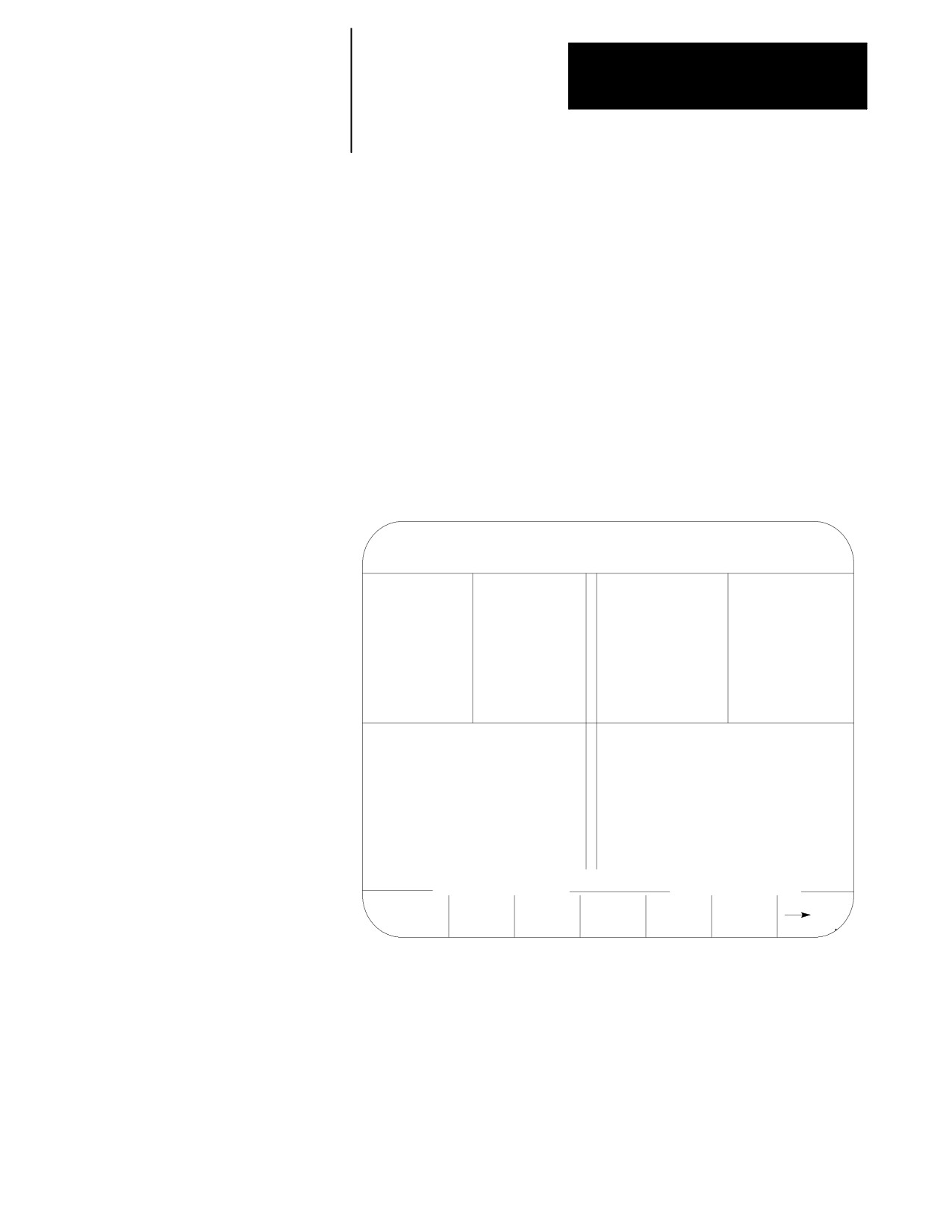
{SPLIT ON/OFF}
The split screen softkey is only available if your system installer has
purchased the dual-process option.
When you press the {SPLIT ON/OFF} softkey, you can view information
for both processes. The screen displays two 40-column screens on one
80-column screen. Process 1 is displayed on the left, and process 2 is
displayed on the right. The active process appears in reverse video.
You can display axis display, M-code, G-code, and large axis screens as a
split screens.
Important: You can only select one process on the split screen at a time.
The selected process appears in reverse video. If only one process is
AMPed, the split screen display is disabled.
E-STOP
PROGRAM [MM]
F
PROGRAM [MM]
F
X
0.000
S
X
0.000
S
Z
0.000
Z
0.000
T
T
U
0.000
U
0.000
MEMORY
AUTO STOP N1999
MEMORY
AUTO STOP N9999
N001G90:
N001G90:
N002G70:
N002G70:
N003M101:
N003M101:
<FRONT TURRET>
<REAR TURRET>
PRGAM
MACRO
PRGRAM
SYSTEM
OFFSET
MANAGE
PARAM
CHECK
SUPORT
8-21
Chapter 8
Displays and Graphics
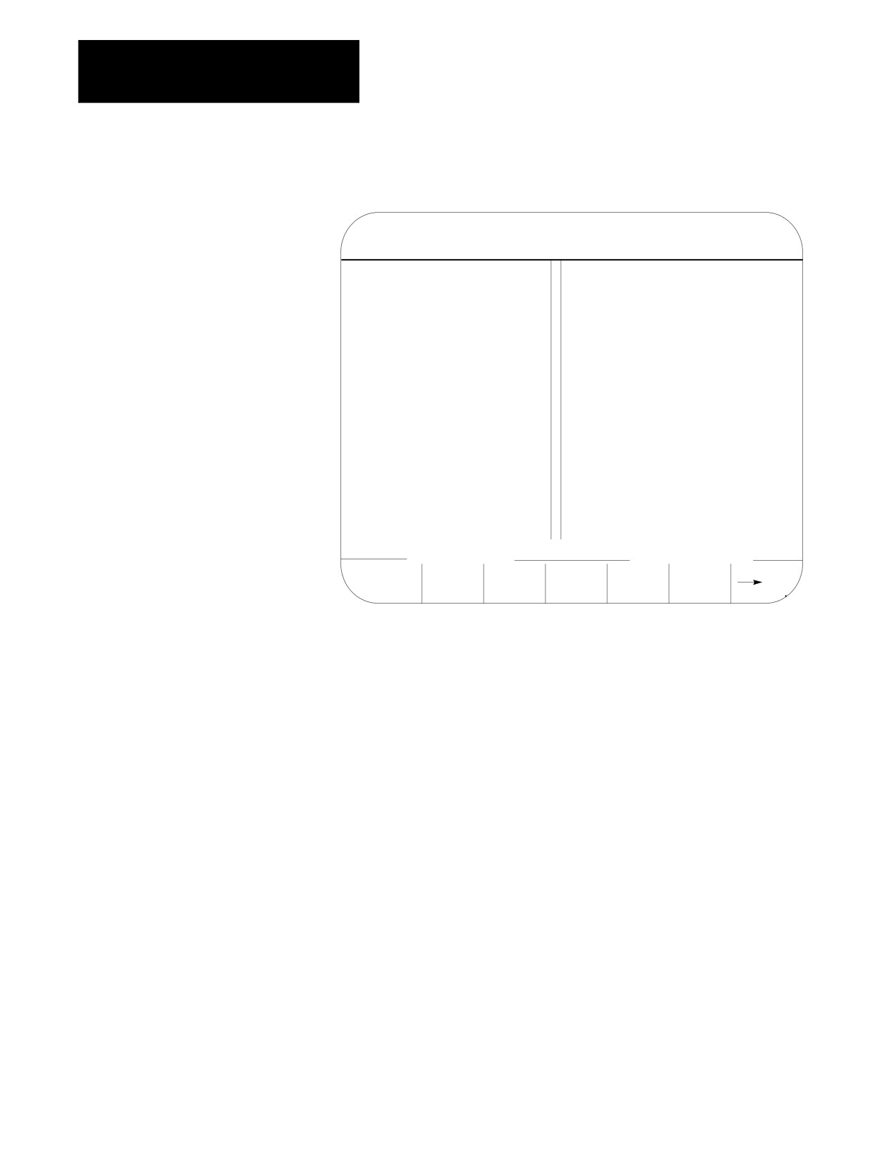
A large screen display makes it easier for you to see the axes.
E-STOP
PROGRAM [MM]
PROGRAM [MM]
X 0.000
X 0.000
Z
0.000
F
0.000
IPM
S
O
F
0.000
IPM
S
O
<FRONT TURRET>
<REAR TURRET>
PRGRAM
ABS
TARGET
DTG
AXIS
SELECT
8.2
If desired the system installer has the option of configuring custom screens
that will show up on the CRT. These screens may be activated through an
PAL Display Page
input to PAL (such as a switch or push button) or by the use of softkeys
also defined by the system installer. These screens may have their own
softkey tree configuration or parameters to assign. Refer to the system
installers documentation for details on the operation of any PAL display
pages that may be defined on your system.
PAL display pages may be accessed in either automatic, manual, or MDI
modes. If the control is in MDI mode when a PAL display is active the
MDI prompt will be available in the normal position on the screen. This
will however prevent the operator from typing in any input for that screen
using the keyboard. Any data typed in on the keyboard will be used for an
MDI operation.
When changing the value of some parameter on the PAL display page, part
program execution is not typically interrupted. If some data that is used in
a currently executing part program is changed the control will handle that
data in the following manner:
8-22
Chapter 8
Displays and Graphics
If the parameter altered is used in the currently executing program block,
that value will not be activated until the following block (unless a cutter
compensation value is being altered).
If the parameter is altered in a block that is within the controls look ahead
range (refer to chapter 22 for details on block look ahead) then the look
ahead blocks are re-setup and the new parameter value is incorporated in
them (unless a cutter compensation value is being altered).
If a cutter compensation value is being altered the control will not re-setup
any blocks in the block look ahead. If the modified value is currently
active the block look ahead buffer is re-setup with the new offset value. If
the modified value is not currently the active value the control will display
an error message.
8.3
The 9/Series control is equipped to display all screens, softkeys, and
messages in multiple languages. Functionality of the 9/240 language
Changing Languages
function is somewhat different than other 9/Series controls.
Press the {SWITCH LANG} softkey to access these languages.
(softkey level 1)
PRGRAM
OFFSET
MACRO
PRGRAM
SYSTEM
MANAGE
PARAM
CHECK
SUPORT
FRONT
ERROR
PASS-
SWITCH
PANEL
MESAGE
WORD
LANG
Each time you press the {SWITCH LANG} softkey, the language displayed on
the screen changes. The system installer can password protect this softkey.
9/230, 9/260, and 9/290 CNCs
These control types are capable of displaying two languages. Your system
installer selects the languages and the order in which they are displayed.
Refer to your system installers documentation for details on which
languages your system supports. The default languages are English and
German.
8-23
Chapter 8
Displays and Graphics
9/240 CNCs
The 9/240 control is equipped to display four languages. The languages
available and the order they are displayed are fixed in this order:
English
Italian
Japanese
German
8.4
QuickCheck and active program graphics function similarly. They both
plot tool paths. The following section describes how to use both types of
Graphics
graphics and distinguishes how they differ.
Use the QuickCheck with graphics feature to test a program for correct
syntax and to visually check if the tool path plotted by the part program is
correct. No actual axis motion takes place during QuickCheck. The
QuickCheck with graphics feature is identical to the QuickCheck feature
described in chapter 8 with the exception that there is an added graphics
capability. Using the graphics feature is optional with QuickCheck;
programs can be checked as described in the QuickCheck section without
using graphics. QuickCheck also lets you single-block through the part
program.
Use the active program graphics feature to plot the actual tool path of a
program on the screen that is executing in either the axis inhibit, dry run,
or part production mode. The graphics feature is optional and you do not
need to use it when you run a program.
8.4.1
If you have not already selected a a program to execute, select one now,
following these steps:
Selecting the Program for
Graphics
1.
Press the {PRGRAM CHECK} softkey.
(softkey level 1)
PRGRAM
OFFSET
MACRO
PRGRAM
SYSTEM
MANAGE
PARAM
CHECK
SUPORT
FRONT
ERROR
PASS-
SWITCH
PANEL
MESAGE
WORD
LANG
8-24
Chapter 8
Displays and Graphics
2.
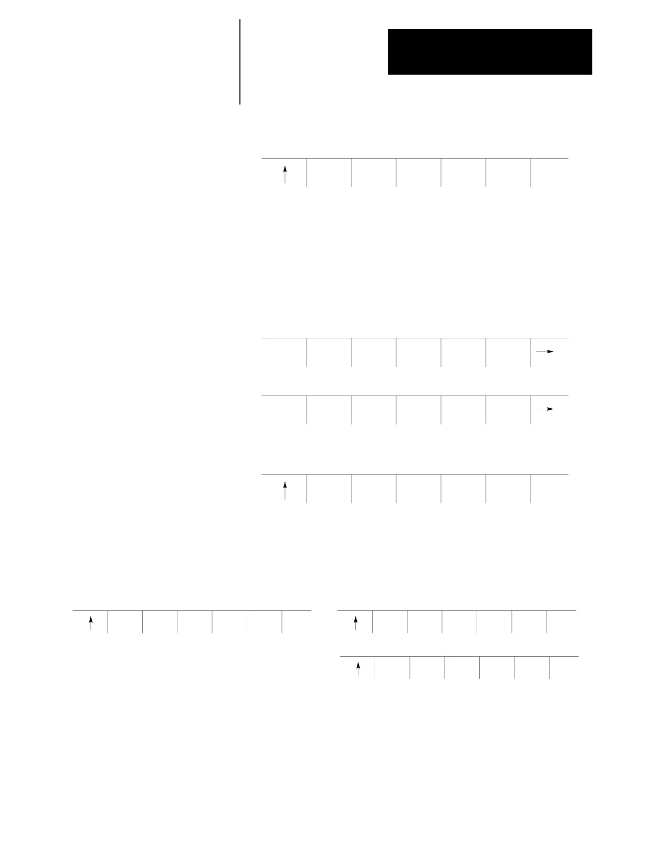
Select a program. Press {SELECT PRGRAM}.
(softkey level 2)
SELECT
QUICK
STOP
T PATH
T PATH
PRGRAM
CHECK
CHECK
GRAPH
DISABL
3.
Use the up and down cursors to select a program.
4.
Press {ACTIVE PRGRAM} to return to level 2 and activate the program.
8.4.2
Follow these steps to run graphics:
Running Graphics
1.
Press the {PRGRAM CHECK} softkey.
(softkey level 1)
PRGRAM
OFFSET
MACRO
PRGRAM
SYSTEM
MANAGE
PARAM
CHECK
SUPORT
FRONT
ERROR
PASS-
SWITCH
PANEL
MESAGE
WORD
LANG
2.
Select a program. Press {SELECT PRGRAM}.
(softkey level 2)
SELECT
QUICK
STOP
T PATH
T PATH
PRGRAM
CHECK
CHECK
GRAPH
DISABL
3.
Use the up and down cursors to select a program.
4.
Select graphics. Follow the appropriate steps:
Active Graphics
QuickCheck Graphics
(softkey level 2)
(softkey level 2)
SELECT
QUICK
STOP
T PATH
T PATH
SELECT
QUICK
STOP
T PATH
T PATH
PRGRAM
CHECK
CHECK
GRAPH
DISABL
PRGRAM
CHECK
CHECK
GRAPH
DISABL
(softkey level 3)
GRAPH
SYNTAX
ONLY
The graphics you select remains active until you disable graphics.
5.
Press the <CYCLE START> button to plot the part program.
8-25
Chapter 8
Displays and Graphics
The control for both QuickCheck and active graphics continues to plot tool
paths, even if the graphics screen is not displayed. Actual display of the
tool paths is only possible on the graphics screen. When the graphics
screen is displayed again, any new tool motions appear on the screen.
While on the graphics screen only the currently executing block is
displayed. The currently executing block is displayed on line 22 of the
CRT, and it is limited to 80 characters. Any characters following the
eightieth character in a block are truncated for display purposes only.
Important: If the graphic screen does not display the tool path you want,
you may need to alter the graphic parameters. To change your graphic
parameters see page 8-27.
Scale
When you first activate the graphics screen, the scale for the axes is based
on the software overtravel limits (see chapter 13). The selected axis with
the largest software overtravel limit is used as the scale axis for the
graphics screen. The range for the other axis is then scaled up to create a
proportional graph. This helps keeps the shapes on the graph proportional
(circles look like circles not ellipses etc.).
The zero of the scale for each axis is determined by the currently active
work coordinate system (G54-G59.3). Any time that a coordinate system
is changed, the scale automatically changes to match the current position
with the new position in the new coordinate system. Any offsets to the
work coordinate system also change the scale for the axes. When the
scale changes, the plot of the tool path does not change; only the scale
changes to match the plot to the new coordinate system.
If you want to adjust the scale, use zoom window. Refer to page 8-33.
Important: You can adjust the scale factor automatically to match the size
of the part program currently being executed. To do this, use the auto size
feature described in chapter 1.
8-26
Chapter 8
Displays and Graphics
8.4.3
In some cases, you may want to operate without graphics. For example,
you cannot edit a part program using QuickView while in graphics, or you
Disabling Graphics
may want to speed up processing by disabling graphics.
To disable graphics, press the appropriate softkey:
Active Graphics
QuickCheck Graphics
(softkey level 2)
(softkey level 2)
SELECT
QUICK
STOP
T PATH
T PATH
SELECT
QUICK
STOP
T PATH
T PATH
PRGRAM
CHECK
CHECK
GRAPH
DISABL
PRGRAM
CHECK
CHECK
GRAPH
DISABL
When you attempt to use a feature that cannot be run with active graphics.
You will be prompted to disable graphics.
A {T PATH DISABLE} softkey also appears on level three. If you press the
{PRGRAM MANAGE} softkey on level one, followed by
{ACTIVE PRGRAM} softkey on level 2, you will have the option to disable
graphics. Both {T PATH DISABLE} keys deactivate graphics.
8.4.4
QuickCheck graphics and active graphics share some of the same graphic
parameters. This section describes the graphic parameters they share and
Changing Parameters
identifies their separate parameters.
When the parameter screen is displayed, it always shows the last set of
parameter values that were saved. If you disable graphics, the control still
saves the last set of parameters. However, parameters are not saved after
you turn the power off.
QuickCheck and active graphics share the same parameter setup. If you
change a parameter in one graphic feature, it is saved to the other.
Important: Any time you change one of the parameters on the graphics
parameter screen (with the exception of auto erase), it causes any tool
paths that may have already been drawn on the actual active graphics
screen to be cleared. Drawing resumes from the point that the program is
currently executing.
Important: If you use a color system and you want a different tool color
representation, see chapter 21 for details on changing tool color.
8-27
Chapter 8
Displays and Graphics
You may want to change the parameters to alter your graphics. If you want
to view a different graphics screen, you must change the default values for
the parameters. These are the default parameter values for QuickCheck:
PROCESS SPEED:
[FAST]
RAPID TRAVERSE:
[ON]
AUTO SIZE
[OFF]
GRID LINES
[OFF]
OVERTRAVEL/ZONE LINES
[OFF]
MAIN PROGRAM SEQUENCE STARTING #[0]
MAIN PROGRAM SEQUENCE STOPPING #[0]
These are the default parameter values for active graphics:
RAPID TRAVERSE
[ON]
AUTO ERASE
[ON]
AUTO SIZE
[OFF]
GRID LINES
[OFF]
OVERTRAVEL/ZONE LINES
[OFF]
Follow these steps to change your parameters. We assume you have
already completed the procedure to run graphics. See page 8-25 for details
on running a graphics program.
1.
To load parameters, press {GRAPH SETUP}.
(softkey level 4)
CLEAR
MACHIN
ZOOM
ZOOM
GRAPH
GRAPHS
INFO
WINDOW
BACK
SETUP
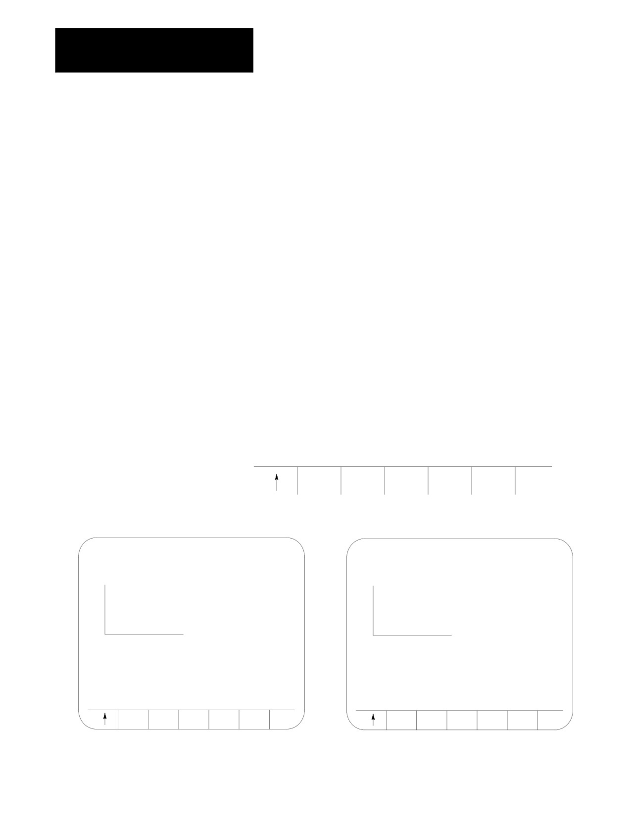
The control displays these graphics parameter screens:
CHECK RUN GRAPHICS PARAMETERS
ACTIVE PROGRAM GRAPHICS PARAMETER
USE <ARROW KEYS> TO SELECT PARAMETERS
USE <ARROW KEYS> TO SELECT PARAMETERS
ACTIVE PROGRAM: G52
ACTIVE PROGRAM: G21
X
X
Z
Z
PROCESS SPEED
FAST
RAPID TRAVERSE ON
RAPID TRAVERSE
ON
AUTO ERASE OFF
AUTO SIZE
OFF
AUTO SIZE
OFF
GRID LINES
OFF
GRID LINES
OFF
OVERTRAVEL/ZONE LINES
OFF
OVERTRAVEL/ZONE LINES
OFF
MAIN PROGRAM SEQUENCE STARTING #: 0
MAIN PROGRAM SEQUENCE STARTING #: 0
DEFALT
SAVE
DEFALT
SAVE
PARAM
PARAM
PARAM
PARAM
8-28
Chapter 8
Displays and Graphics
2.
Set Select Graph. Use the up and down cursor keys to select the
axes. Then set them by pressing the left or right cursor keys. The
data for the selected axes change each time you press the left or right
cursor key.
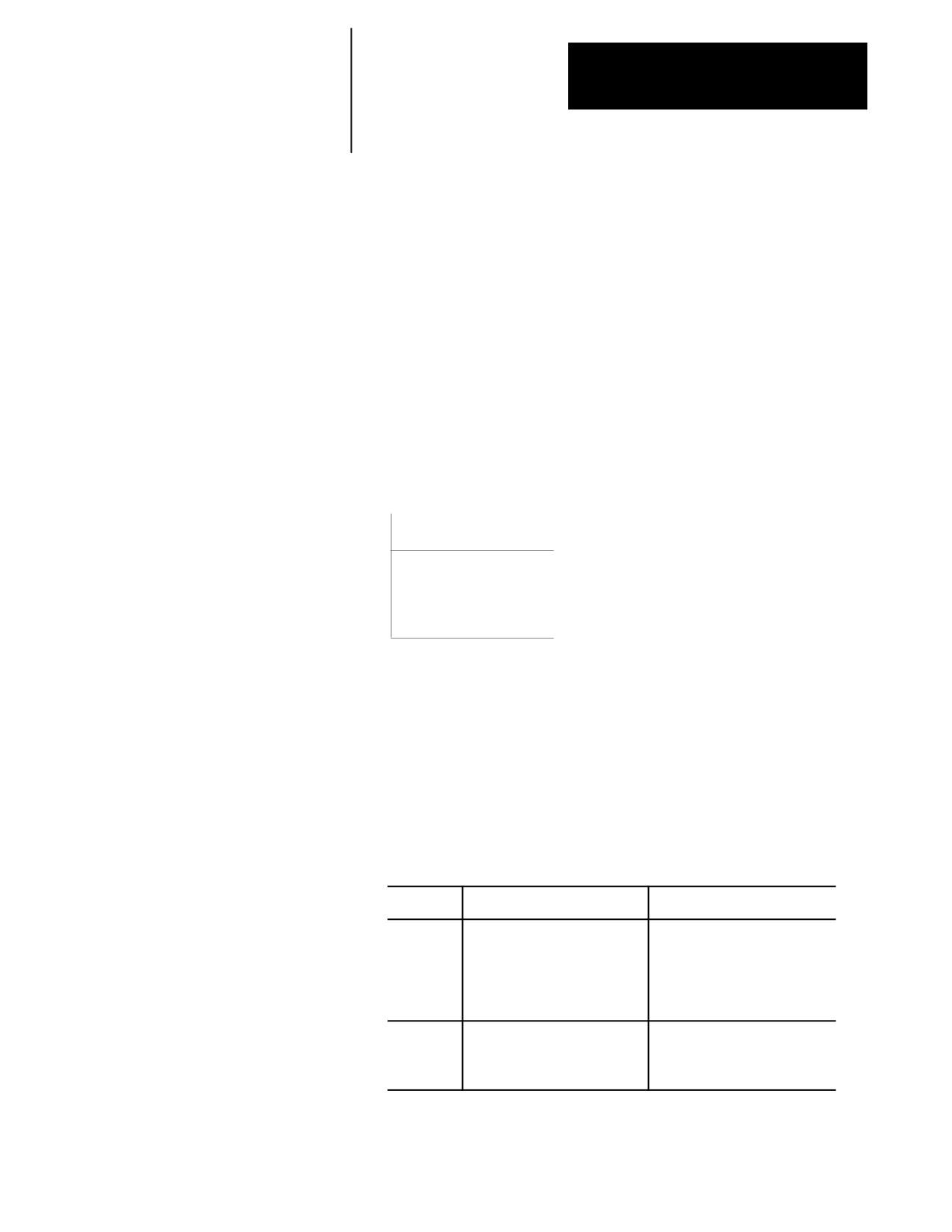
A pictorial representation of the selected graph, which is determined
by the selected axes, is displayed on the screen.
You have three fields that you can adjust. The axes are shown as
horizontal and vertical axes. If you choose a third axis for display, it
appears as a horizontal axis above the first one. Only linear axes can
be selected for display on the graphics screen.
For example:
If the X, Y, and Z axes are selected, this representation appears:
Y
X
Z
Choose a set of axes that best displays the current program’s cutting
path.
3.
Set Rapid Traverse. Use the up and down cursor keys to select the
parameter. Set it by pressing the left or right cursor keys. The value
for the selected parameter changes each time you press the left or
right cursor key.
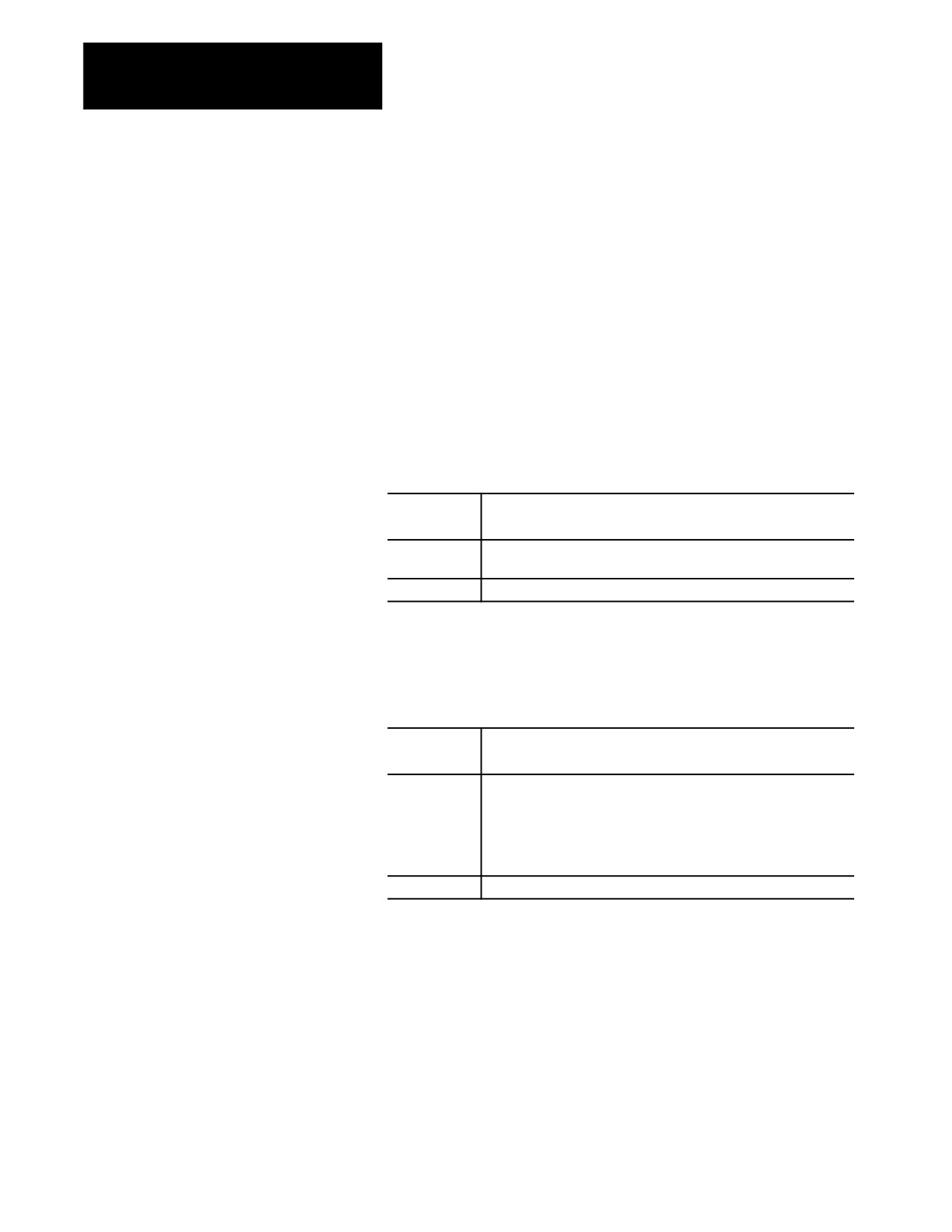
There are two options available for the rapid traverse parameter:
Choosing:
Causes monochrome:
Causes color:
On
rapid moves to be drawn with a
rapid moves are always in red,
dashed line and other moves to
unless the rapid moves overwrite
be drawn with a solid line.
green feed lines. If this is the
case, the control uses yellow for
the rapid moves that overlap the
green feed lines.
Off
graphics do not draw any move
graphics do not draw any move
that is made in rapid traverse. All
that is made in rapid traverse.
other moves are drawn with a
solid line.
8-29
Chapter 8
Displays and Graphics
4.
Set Auto Size. Use the up and down cursor keys to select the
parameter. Set auto size by pressing the left or right cursor keys. The
value for the selected parameter changes each time you press the left
or right cursor key.
If you turn this parameter “ON”, the control re-sizes the graphics
screen to the size of the programmed part. To use this feature, turn
this parameter “ON”, then run the part program. When the part
program is finished, the control re-sizes the graphics screen then turns
this parameter “OFF.”
5.
Set Grid Lines. Use the up and down cursor keys to select the
parameter. Set it by pressing the left or right cursor keys. The data
for the selected parameter changes each time you press the left or
right cursor key.
When this
The control:
parameter is:
On
overlays the graphics screen with grid lines. These grid lines are
solid lines drawn at the axis coordinate tick marks.
Off
does not display lines.
6.
Set Overtravel Zone Lines. Use the up and down cursors to select
the parameter. Set it by pressing the left or right cursor keys. The
data for the selected parameter changes each time you press the left or
right cursor key.
When this
The control:
parameter is:
On
draws overtravel/zone lines on the graphics screen. These
overtravel/zone lines correspond to the active software overtravel
limits and the programmable zone limits. The software overtravel
limits are specified in AMP by your system installer. The
programmable zone limits must be programmed by the operator. The
software overtravel and programmable zone lines are dotted lines.
Off
does not display lines.
8-30