9/Series CNC Lathe. Operation and Programming Manual - page 7
Chapter 7
Running a Program
7.2
Before selecting a part program, you must tell the control where this part
program is currently residing. There are 3 options here:
Selecting a Part
Program
Input Device
the program can be resident in the control’s memory
the program can be resident on a peripheral device attached to port A
such as a tape reader (refer to system installers documentation)
the program can be resident on a peripheral device attached to port B
such as a taper reader (refer to system installers documentation).
Important: If you select a peripheral device attached to one of the two
communication ports (A or B), that port must have been previously
configured to communicate to that specific peripheral device. Refer to
chapter 9 for details on communications setup for ports A and B. Selecting
a program from the control’s memory is the default configuration of the
control. If do not select port A or B, the input device should remain at its
default of control memory and the following procedure should be
unnecessary.
To select the part program input device:
1.
Press the {PRGRAM MANAGE} softkey.
(softkey level 1)
PRGRAM
OFFSET
MACRO
PRGRAM
SYSTEM
MANAGE
PARAM
CHECK
SUPORT
FRONT
ERROR
PASS-
SWITCH
PANEL
MESAGE
WORD
LANG
2.
Press the {INPUT DEVICE} softkey.
(softkey level 2)
ACTIVE
EDIT
RESTRT
DISPLY
COPY
PRGRAM
PRGRAM
PRGRAM
PRGRAM
PRGRAM
DELETE
VERIFY
PRGRAM
RENAME
INPUT
PRGRAM
PRGRAM
COMENT
PRGRAM
DEVICE
REFORM
CHANGE
MEMORY
DIR
7-5
Chapter 7
Running a Program
3.
Press the softkey corresponding to the location where the part
program is to be read from, {FROM PORT A}, {FROM PORT B}, or
{FROM MEMORY}.
(softkey level 3)
FROM
FROM
FROM
PORT A
PORT B
MEMORY
To activate a part program, it must be selected as described on page 8.3.
7.3
To select a program for automatic execution, follow these steps:
Selecting a Program
Important: Consider the following when selecting a program:
The control cannot select a program for execution if that program file is
still open for editing. See chapter 5 to learn how to exit the edit mode.
Your system installer may have written PAL to allow some other
method of part program selection. Refer to the documentation prepared
by your system installer for additional information.
Before selecting a part program to activate, the input device must have
been previously selected as described on page 7-5. The default
condition selects the part program out of control memory.
If a program was previously activated and not deactivated, the control
cannot select a different part program. If you want a different part
program, you must first deactivate the active program as described on
page 7-8. You can use a different method to select a program; it is
described in chapter 7.
To select a program for automatic execution:
1.
Press the {PRGRAM MANAGE} softkey.
(softkey level 1)
PRGRAM
OFFSET
MACRO
PRGRAM
SYSTEM
MANAGE
PARAM
CHECK
SUPORT
FRONT
ERROR
PASS-
SWITCH
PANEL
MESAGE
WORD
LANG
7-6
Chapter 7
Running a Program
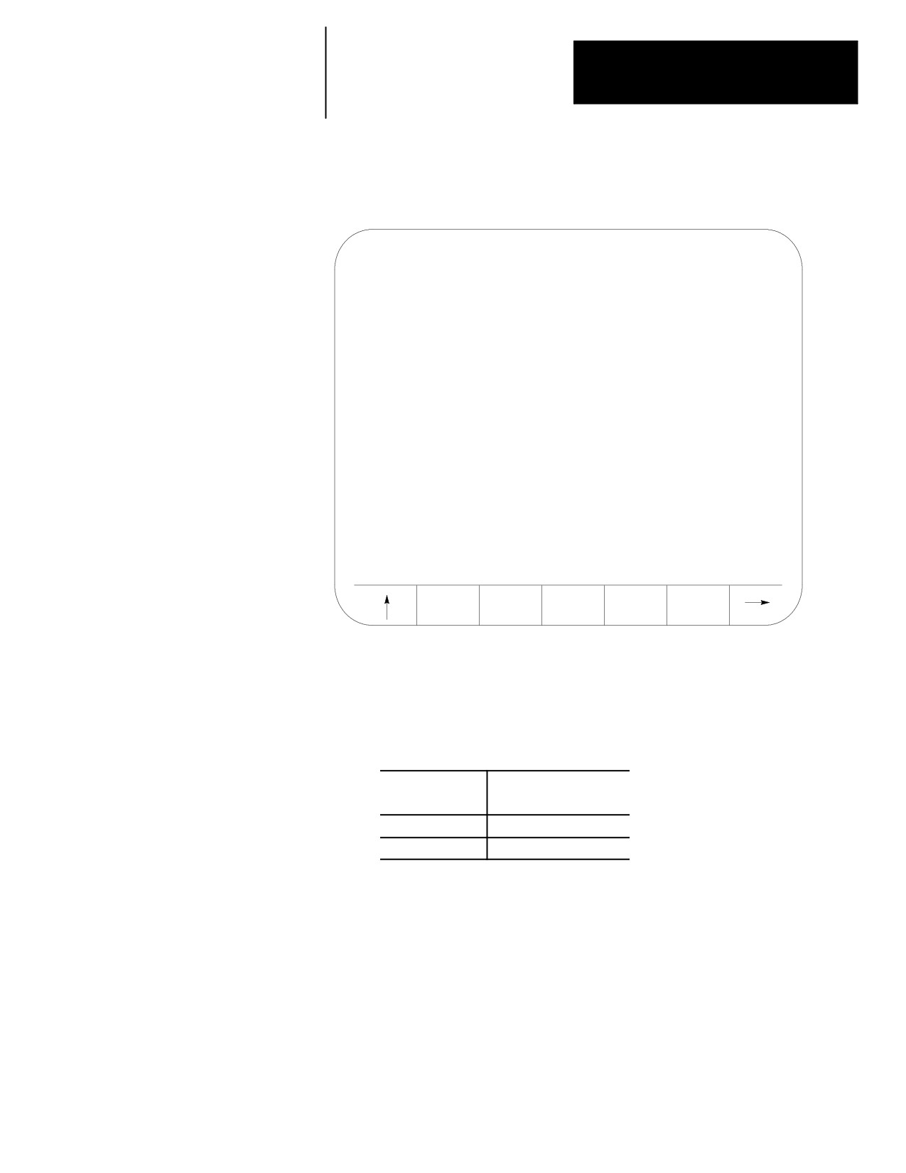
This screen appears:
SELECTED PROGRAM:
DIRECTORY
PAGE
1
OF
1
NAME
SIZE
COMMENT
TEST
AE
3.9
O12345
1.3
SUB TEST 1
MAIN
1.3
SHAFT2
1.3
THIS IS A TEST PROGRAM
XXX
1.3
5 FILES
137.8 METERS FREE
ACTIVE
EDIT
RESTRT
DISPLY
COPY
PRGRAM
PRGRAM
PRGRAM
PRGRAM
PRGRAM
Important: This screen shows program TEST as active and being edited.
Make sure no part program is currently already active. If a part program
is currently active, the control cannot select a different part program until
the currently active one is deactivated. See page 7-8 to learn how to
deactivate a part program.
If a program is:
This appears to the right
of a program name:
active
A
being edited
E
2.
Key in the name of the part program to activate. If the program is
being selected from control memory, the › or fl cursor keys may be
used to select the program to activate from the directory screen.
If the part program is being selected from a peripheral device
(attached to port A or port B), you must manually key in the part
program name. Make sure the peripheral device is on and ready to
output the part program. You might need to perform a search
operation when selecting a program from a peripheral device to find
the tape location containing the desired part program.
7-7
Chapter 7
Running a Program
3.
Press the {ACTIVE PRGRAM} softkey to activate the selected program.
The control displays the part program name, followed by the first few
blocks of the selected program.
Important: The following softkey level 2 indicates that the control is
using control memory as an input device. If the input device is some
device other than control memory, some of these softkeys are not available.
(softkey level 2)
ACTIVE
EDIT
RESTRT
DISPLY
COPY
PRGRAM
PRGRAM
PRGRAM
PRGRAM
PRGRAM
DELETE
VERIFY
PRGRAM
RENAME
INPUT
PRGRAM
PRGRAM
COMENT
PRGRAM
DEVICE
REFORM
CHANGE
MEMORY
DIR
Important: Before you can execute the program, you must place the
control in automatic mode.
7.4
To select a different part program for automatic execution, you must
Deselecting a Part Program
deactivate the part program that is currently active. Follow these steps:
1.
Press the {PRGRAM MANAGE} softkey. The control displays the
program directory screen.
(softkey level 1)
PRGRAM
OFFSET
MACRO
PRGRAM
SYSTEM
MANAGE
PARAM
CHECK
SUPORT
FRONT
ERROR
PASS-
SWITCH
PANEL
MESAGE
WORD
LANG
7-8
Chapter 7
Running a Program
2.
Press the {ACTIVE PRGRAM} softkey. The control displays the first
few blocks of the currently active program.
(softkey level 2)
ACTIVE
EDIT
RESTRT
DISPLY
COPY
PRGRAM
PRGRAM
PRGRAM
PRGRAM
PRGRAM
DELETE
VERIFY
PRGRAM
RENAME
INPUT
PRGRAM
PRGRAM
COMENT
PRGRAM
DEVICE
REFORM
CHANGE
MEMORY
DIR
3.
If the program selected is not the active program you wanted, press
the {DEC-ACT PRGRAM} softkey. The control deactivates the part
program and return to the directory screen.
(softkey level 3)
DE-ACT
SEARCH
MID ST
T PATH
T PATH
PRGRAM
PRGRAM
GRAPH
DISABL
SEQ
TIME
STOP
PARTS
7.5
Use the Program Search feature to begin program execution from some
Program Search {SEARCH}
block other than the beginning of the program. This feature requires the
operator to establish the necessary G-, M-, S-, F-, and T-words, work
coordinate offsets, etc. that should be active for that block’s execution.
The control can start a program at a chosen block and establishing any
previous G-, M-, S-, F-, and T-words, work coordinate offsets, etc. that
were established in previous blocks using the search with memory feature.
For details, see page 7-12.
The program search feature is not effective for subprograms and
paramacros; only blocks that are in the main program can be searched.
7-9
Chapter 7
Running a Program
To perform a program search operation:
1.
Press the {PRGRAM MANAGE} softkey. The program to search must
have been previously selected for automatic execution as described in
page 7-6.
(softkey level 1)
PRGRAM
OFFSET
MACRO
PRGRAM
SYSTEM
MANAGE
PARAM
CHECK
SUPORT
FRONT
ERROR
PASS-
SWITCH
PANEL
MESAGE
WORD
LANG
2.
Press the {ACTIVE PRGRAM} softkey.
(softkey level 2)
ACTIVE
EDIT
RESTRT
DISPLY
COPY
PRGRAM
PRGRAM
PRGRAM
PRGRAM
PRGRAM
DELETE
VERIFY
PRGRAM
RENAME
INPUT
PRGRAM
PRGRAM
COMENT
PRGRAM
DEVICE
REFORM
CHANGE
MEMORY
DIR
3.
Press the {SEARCH} softkey.
(softkey level 3)
DE-ACT
SEARCH
MID ST
T PATH
T PATH
PRGRAM
PRGRAM
GRAPH
DISABL
SEQ
TIME
STOP
PARTS
7-10
Chapter 7
Running a Program
4.
Choose from the 6 search options:
If you are searching for:
Press this softkey:
a sequence number
{N SEARCH}
an O-word
{O SEARCH}
the end of each block
{EOB SEARCH}
the program one line at a time
{SLEW}
a specific character string
{STRING SEARCH}
the beginning of your next program
{NEXT PRGRAM} This
softkey is available only if your
input device has been configured
as a tape reader. See chapter 9
on input device selection.
5.
When you use the SLEW or the EOB search options:
If you want to:
Press this softkey:
move to the next or previous blocks in the
{FORWRD} or
program
{REVRSE}
return to the top of the program (the
{TOP OF PRGRAM}
beginning of the first block
exit, when the desired block is found
{EXIT}
Important: When performing an EOB search, the search is executed from
the beginning of the part program, NOT from the point of display.
When you use the N search, O search, or STRING search features,
first key in the desired N number, O number, or character string you
want to search for. After it has been keyed in:
If you want to:
Press this softkey:
start the search
[TRANSMIT]
search for the entered value in the forward or
{FORWRD} or {REVRSE}
reverse direction
return to the top of the program (the
{TOP OF PRGRAM}
beginning of the first block)
exit when the desired block is found.
{EXIT}
If no number is keyed in for an N or O search, the control simply
searches for the next N- or O-word in the program.
7-11
Chapter 7
Running a Program
When you press the {NEXT PRGRAM} softkey, the control first
searches for a valid program end code. See setting communications,
chapter 9. After it finds the program end code, it advances to the
program start code of the next program. If the current program is the
last program on the tape, the message “SERIAL
COMMUNICATION ERROR #5” appears on the screen indicating a
time-out error.
Important: If performing a STRING search, program execution begins at
the beginning of the block that contains the desired character string. This
is not necessarily the location of the string in the program block.
CAUTION: It may be necessary to position the cutting tool at a
location that allows this block to execute without damaging the
workpiece or cutting tool. This can be done through a manual
operation or through MDI.
7.6
Use the Mid-Start Program feature to begin program execution from some
block other than the first block of the program. This feature will scan the
Search With Recall
program as it searches and from within the search area:
{MID
ST
PRGRAM}
send to PAL the last programmed modal G--codes from each modal
group.
send to PAL the last programmed modal M--codes from each modal
group and set its associated PAL strobe (nonmodal codes including
user--defined M--codes are not sent to PAL).
send to PAL the last programmed T code and set its associated PAL
strobe
send to PAL the last programmed auxiliary function code (B--word) and
set its associated PAL strobe
send to PAL the last programmed spindle commanded speed and set its
associated PAL strobe
resolve paramacro equations and assign paramacro variable values (note
on dual process systems shared paramacro variables can be different
than expected depending on the state of the part program in the other
process, also equations that use PAL paramacro variables may also
evaluate differently since no paramacro interaction with PAL occurs
during a search operation).
establishes any work coordinate system, including all offsets and
rotations to the work coordinate system.
7-12
Chapter 7
Running a Program
Important: Incremental moves that occur during a program search with
recall operation, are always referenced from the last known absolute
position in the part program. If no absolute position is specified in the
searched part program blocks, the control will use the current axis position
as the start point for incremental moves.
When a search with recall is performed, the control finds a character string
or sequence number in a specific block for execution to begin from. Note
that execution always begins from the beginning of the block, regardless of
the location in the block of the searched string or sequence number. This
searched block must be a block that would normally be executed during the
full programs execution (a block that would be skipped by some means
such as a jump, etc., cannot be searched for).
The program search with recall feature maybe used to search into any
subprograms or paramacros that may be contained in the main program.
This is provided of course, that the searched block is in the path of normal
program execution.
Important: The search with recall feature will not:
send PAL nonmodal M--codes including user--defined groups 0 -- 3,
group 4, group 5, and group 6 M--codes.
on dual process systems, halt execution for synchronization codes.
read from or write paramacro variables to PAL
on dual process systems, shared paramacro variables between processes
may not be evaluated as desired depending on the status of the other
process.
Important: This feature will not search into any cycle that calls a set of
profile blocks (typically specified with the P-- and Q--word in the cycle).
Refer to the description of your cycle for details on profile blocks.
send to PAL gear change requests based on spindle speed
7-13
Chapter 7
Running a Program
To perform a program search with recall, follow these steps:
1.
Press the {PRGRAM MANAGE} softkey.
(softkey level 1)
PRGRAM
OFFSET
MACRO
QUICK
SYSTEM
MANAGE
PARAM
CHECK
SUPORT
FRONT
ERROR
PASS-
SWITCH
PANEL
MESAGE
WORD
LANG
2.
Press the {ACTIVE PRGRAM} softkey.
(softkey level 2)
ACTIVE
EDIT
RESTRT
DISPLY
COPY
PRGRAM
PRGRAM
PRGRAM
PRGRAM
PRGRAM
VERFY
PRGRAM
DELETE
RENAME
INPUT
PRGRAM
COMENT
PRGRAM
PRGRAM
DEVICE
REFORM
MEMORY
Make sure that the program to search is the currently active program.
If it is not, select it for automatic execution as discussed in section
7.3.
3.
Press the {MID ST PRGRAM} softkey.
(softkey level 3)
DE-ACT
SEARCH
MID ST
T PATH
SEQ
PRGRAM
PRGRAM
GRAPH
STOP
TIME
PARTS
4.
To search for a sequence number press the {SEQ # SEARCH} softkey.
To search for a character string press the {STRING SEARCH} softkey.
(softkey level 4)
SEQ #
STRING
SEARCH
SEARCH
7-14
Chapter 7
Running a Program
5.
Key in the desired character string or sequence number to search for
and press the [TRANSMIT] key. The control locates an @ symbol to
the left of the block immediately before the block that automatic
execution begins from.
If this is not the block to begin execution from press either the:
{CONT} softkey to continue to search for the entered character string
or sequence number.
{TOP OF PRGRAM} to return to the first block in the program.
{QUIT} softkey to end either the sequence number search or the
character string search operations.
(softkey level 5)
CONT
TOP OF
QUIT
EXIT
PRGRAM
CAUTION: When you exit a mid-program start (search with
memory), M- and S-codes are sent to PAL. If, during normal
execution, that program activated a spindle, mid-program start
may also start it. To prevent this, your system installer can use
the $BLKSTAT flag , which indicates the control is in
mid-program start.
6.
Press the {EXIT} or the {EXIT & MOVE} softkey once the program is
at the desired location.
{EXIT} - Use this softkey if the tool is at the exact location for
execution of the searched program block. While the control searches
for your starting block it performs calculations to determine what the
absolute position of the axes should be before your selected block is
executed. If the cutting tool is not at this position when you press the
{EXIT} softkey, the control aborts the mid-start operation. When this
occurs the control displays the message “AXIS POSITION
INCORRECT”.
7-15
Chapter 7
Running a Program
{EXIT & MOVE} - Use this softkey if the tool is not at the exact
location for execution of the searched block. Be aware that the
absolute position of the axes necessary at the start of the searched
block is dependant on the previous blocks. There can be offsets
activated or incremental moves that can make it difficult for you to
determine the exact absolute starting point for the axes. The control
generates a motion block to place the tool at the position necessary to
generate the intended contour when the searched block is executed.
The block generated is always a linear move with a feedrate based on
the last motion block prior to the searched block. If the last motion
block was a cutting move with a feedrate, then the generated block
will be a linear move at that cutting feedrate. If the last motion block
was a rapid move, that the generated block will be a linear move at
the rapid feedrate.
WARNING: It is the responsibility of the system installers PAL
application to make sure proper activation of all necessary
machine functions has occurred before allowing a search with
recall operation to continue. You should verify that all machine
functions are in the correct state before pressing <CYCLE
START>.
A message is generated telling the operator to check that all generated
modal codes are correct. This message reads “WARNING - VERIFY
MODAL CODES”. These modal codes should be checked on the G- or
M-code status screen.
The control begins program execution from the selected block when you
press the <CYCLE START> button. If you have pressed the {EXIT & MOVE}
button the control first executes the generated block to place the tool at the
proper location. If you do not want the control to execute this generated
block you can perform a block reset to abort the generated block.
Program interrupts that are enabled in blocks prior to the searched block
(M96L__P__), are active and available for execution once the active
program begins execution. Interrupts can not be executed while the
mid-program search operation is taking place.
7-16
Chapter 7
Running a Program
7.7
After a program is written or loaded into the control, it should be
thoroughly tested before a part is mounted and machined. The control
Basic Program Execution
offers 3 distinct testing modes in addition to fully automatic operation.
These modes are briefly described below in the order in which they would
normally be implemented.
QuickCheck‰ (see page 7-18) — This mode is a basic syntax checker
for a part program. It checks that proper format and syntax has been
followed. If QuickCheck has been purchased with the graphic option, it
can be used to determine if the proper paths are being generated (refer to
page 9-18 for QuickCheck Graphics). No actual axis motion is
produced during QuickCheck, however, offsets and coordinate system
shifts are performed.
Axis Inhibit (see page 7-20) ---- The axis inhibit mode allows the
execution of a program to take place without moving a selected axis or
axes. Programmed feedrates are active and the program executes in
approximately the same time as normal program execution. Axis
motion is simulated for any of the non-moving axes by all of the
position displays changing at the programmed feedrate. Graphics are
available on the active program graphics screen.
Dry Run (see page 7-21) ---- Dry run simply replaces all F-word
feedrates in a program with a special feedrate determined by the system
installer in AMP. Graphics are available on the active program graphics
screen.
Part Production/Automatic (see page 7-23) ---- In automatic mode all of
the axes are active and all of the programmed feedrates are in effect.
Graphics are available on the active program graphics screen.
All of these modes of execution begin program execution when you press
the <CYCLE START> button.
When you see this to
The control:
the left of the block:
is executing a part program block.
@
has completed the execution of a block. The @ symbol is
usually only seen in single block mode or in cases where it is
necessary to indicate what block automatic execution begins
after.
You can interrupt Axis Inhibit, Dry Run, and Automatic operation by using
any of the operations listed below. Execution can be resumed at the
interrupted location by pressing the <CYCLE START> button.
7-17
Chapter 7
Running a Program
(1) Pressing <CYCLE STOP>
When you press the <CYCLE STOP> button, motion of the cutting tool
decelerates and stops, and the control stops automatic operation. If you
press the <CYCLE STOP> button during a dwell, the dwell is interrupted and
any remaining time/revolutions for the dwell are stored for later execution.
(2) Execution of an M00 or M01 in a Part Program
Execution of:
Description:
M00
the control stops automatic operation after it executes the
remaining commands in the M00 block.
M01
if the OPTIONAL STOP condition is set to ON, the control stops
automatic operation after it executes the remaining commands in
the M01 block. If the OPTIONAL STOP condition is set to OFF,
the M01 is ignored and the control continues executing the part
program as normal. The optional stop condition may be turned off
or on using the Front Panel feature, or through a switch installed
by your system installer.
(3) Entering a Sequence Stop Number
To interrupt execution at a specific block in the part program, use the
sequence stop feature described on page 7-2. The control stops automatic
operation after it completes the commands in the designated block.
(4) Feedhold Status
Your system installer may have written PAL to allow the activation of a
feedhold state through the use of a button or switch. When activated the
control decelerates all moving axes to a feedrate of zero until the feedhold
state is deactivated. For details on using feedhold, refer to documentation
provided by your system installer.
7.7.1
QuickCheck is a basic syntax checker for a part program. It checks that
proper format and syntax have been followed during programming. No
QuickCheck
actual axis motion is produced in QuickCheck mode. The QuickCheck
feature is also available with an optional graphics feature.
If you use the graphics feature, refer to chapter 8 for QuickCheck with
graphics. If you are using a dual-processing system, refer to page 30-4 for
details about how the systems differ.
To use the QuickCheck feature as described below without graphics, the
graphics option must be disabled as described in chapter 8.
7-18

Chapter 7
Running a Program
To use the QuickCheck feature, follow these steps.
1.
Select a program to check as described on page 7-5 and return to
softkey level 1.
2.
Press the {PRGRAM CHECK} softkey.
(softkey level 1)
PRGRAM
OFFSET
MACRO
PRGRAM
SYSTEM
MANAGE
PARAM
CHECK
SUPORT
FRONT
ERROR
PASS-
SWITCH
PANEL
MESAGE
WORD
LANG
3.
Press the {QUICK CHECK} softkey.
(softkey level 2)
SELECT
QUICK
STOP
T PATH
T PATH
PRGRAM
CHECK
CHECK
GRAPH
DISABL
When you press the {QUICK CHECK} softkey, the next softkey level
lets you select graphics.
4.
Press the {SYNTAX ONLY} softkey.
(softkey level 3)
GRAPH
SYNTAX
ONLY
When you press the {SYNTAX ONLY} softkey, it appears in reverse
video.
5.
Press the <CYCLE START> button.
When you press the <CYCLE START> button, the program blocks are
executed.
If a program block contains an error, the program check stops and the
control displays the message “ERROR FOUND.”
To continue checking the remaining program blocks, press the
<CYCLE START> button again. If no more errors are found, the control
displays the message “COMPLETED WITH ERROR (S)” and the part
program is automatically deactivated to allow editing.
If the control finds no errors during QuickCheck the program screen
displays the message “COMPLETED WITH NO ERRORS”. The control
then automatically resets the program to the first block.
7-19
Chapter 7
Running a Program
To disable QuickCheck with or without graphics, press the {STOP CHECK}
softkey.
CAUTION: Note that when a program is run during quick
check mode, the control performs all coordinate system offset
operations. This means that changes to the coordinate systems
or coordinate offset tables are made (G10 blocks, changes to
G92 and G52 offsets, and changes to the active work coordinate
systems G54-G59.9). All of these changes are discarded at any
termination of QuickCheck. The pre-QuickCheck values are
restored when the {STOP CHECK} softkey is pressed. Note that
program changes to the active offset or tool offset tables are
not made in QuickCheck mode.
7.7.2
When you activate AXIS INHIBIT, the control can execute a part program
Axis Inhibit Mode
without moving specified axes. The control simulates axis motion by
updating the axis location and feedrate displays, using the commanded
feedrates, acceleration, and deceleration. If graphics are being used the
tool paths of any inhibited axis are still drawn on the graphics screen.
The program is executed in approximately the same amount of time as it
would be in automatic mode, even though some or all axes may not move.
You can use the axis inhibit feature in conjunction with Dry Run.
WARNING: When testing a program using Axis Inhibit the
control still recognizes and executes M-, B-, S-, and T-codes.
To ignore M-, B-, S-, and T-codes, execute Axis inhibit in
conjunction with miscellaneous function lock. See page 7-2.
You can activate AXIS INHIBIT to inhibit motion of any or all of the axes
depending on the configuration determined by your system installer. This
includes jogging moves. When axis motion has been inhibited for a single
axis, the remaining axes still execute normally and the axis location display
is updated as if axis motion were occurring on all axes.
WARNING: Axes not selected for axis inhibit move as they
would if the program were executed in automatic mode.
7-20
Chapter 7
Running a Program
You can activate the Axis Inhibit feature using a switch installed by your
system installer (see documentation provided by the system installer) or by
using the {FRONT PANEL} softkey (see page 2-13). The control must be in
cycle stop or E-Stop to activate or deactivate the Axis Inhibit feature. Any
attempt to activate or deactivate the feature during program execution or
when in cycle suspend or feedhold states is ignored. Attempts to activate
the Axis Inhibit feature during jogging are also ignored.
Press <CYCLE START> to program execution with the Axis Inhibit feature.
Make sure you select a program for execution. See page 7-6.
You can stop program execution with Axis Inhibit at any time by using any
of the methods described for normal program execution or by pressing the
<EMERGENCY STOP> button.
WARNING: Axes not selected for axis inhibit move as they
would if the program were executed in automatic mode.
The spindle motion may also be inhibited by using a switch installed by
your system installer. See the documentation provided by your system
installer. The spindle cannot use the {FRONT PANEL} softkey to activate
the Axis Inhibit feature.
7.7.3
The Dry Run function permits the checking of a part program to make
sure that machine motions are correct. It is intended to be executed
Dry Run Mode
without the material or part mounted. The dry run function replaces all
programmed feedrates with the maximum cutting feedrate. Jogging moves
and moves that are programmed using rapid traverse (G00) are not affected
by dry run.
The Axis Inhibit feature can be used in conjunction with Dry Run if
desired.
If you use the external decel feature simultaneously with the Dry Run
feature, the feedrates that are assigned to External decel feature are used
and the Dry run request is ignored.
7-21
Chapter 7
Running a Program
You can use the <FEEDRATE OVERRIDE> to modify the cutting feedrate.
Your system installer determines in AMP if rapid feedrates are overrides
by the <RAPID FEEDRATE OVERRIDE> switch/button or the <FEEDRATE
OVERRIDE> switch during Dry Run.
CAUTION: When testing a program using Dry Run, the
control still recognizes and executes M-, B-, S-, and T-codes.
To ignore M-, B-, S-, and T-codes, execute Dry Run in
conjunction with miscellaneous function lock. See section
8.1.2.
WARNING: Your system installer can write PAL to allow the
operator to select DRY RUN at any time. This means that
during normal automatic operation, the operator can select
maximum cutting feedrate and replace all feedrates
programmed with an F-word with the AMP assigned DRY RUN
feedrate. This can result in damage to the machine, part, or
injury to the operator.
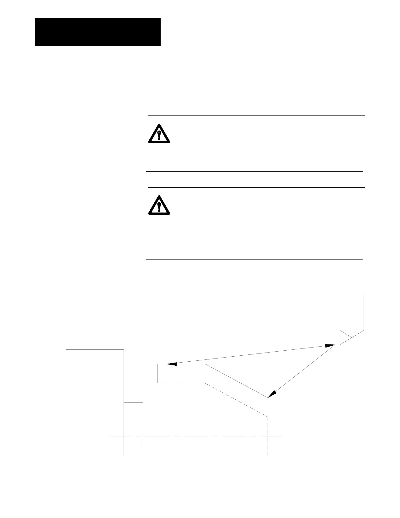
Figure 7.2
Dry Run
CUTTING
TOOL
CHUCK
WORKPIECE
7-22

Chapter 7
Running a Program
The Dry Run feature can be activated using a switch installed by your
system installer (see documentation provided by your system installer) or
by using the {FRONT PANEL} softkey (see page 2-13).
7.7.4
Automatic mode is the normal operating mode of the control. A program
Part Production/Automatic
that is run in the automatic mode is executed with all of the axes active and
all of the programmed feedrates active. Graphics is also available as
Mode
described in chapter 8.
To select the automatic mode, place the <MODE SELECT> switch/button (on
the MTB panel) in the AUTO position. If not equipped with a mode select
switch, use the {FRONT PANEL} softkey.
Automatic mode is the default mode whenever AUTO appears on the Main
Menu screen, and it is always active unless one of the program checking
modes has been selected.
Figure 7.3
Main Menu Screen in AUTO Mode
E-STOP
PROGRAM[ MM
]
F
.000 MMPM
Z
00000.000
S 0
R X
00000.000
T 1
C
359.99
MEMORY 30000 AUTO STOP
N 99999
(First 4 blocks,
of executing program shown here)
(PAL messages)
PRGRAM
OFFSET
MACRO
PRGRAM
SYSTEM
MANAGE
PARAM
CHECK
SUPORT
In automatic mode, the control manages machine operations according to
the commands in a part program.
7-23
Chapter 7
Running a Program
Command:
Process:
CYCLE START
begins part program execution
CYCLE STOP
stops part program execution
WARNING: Always test a program prior to automatic
operation. Always verify that the workspace is clear and all
safety features are intact before pressing <CYCLE START>.
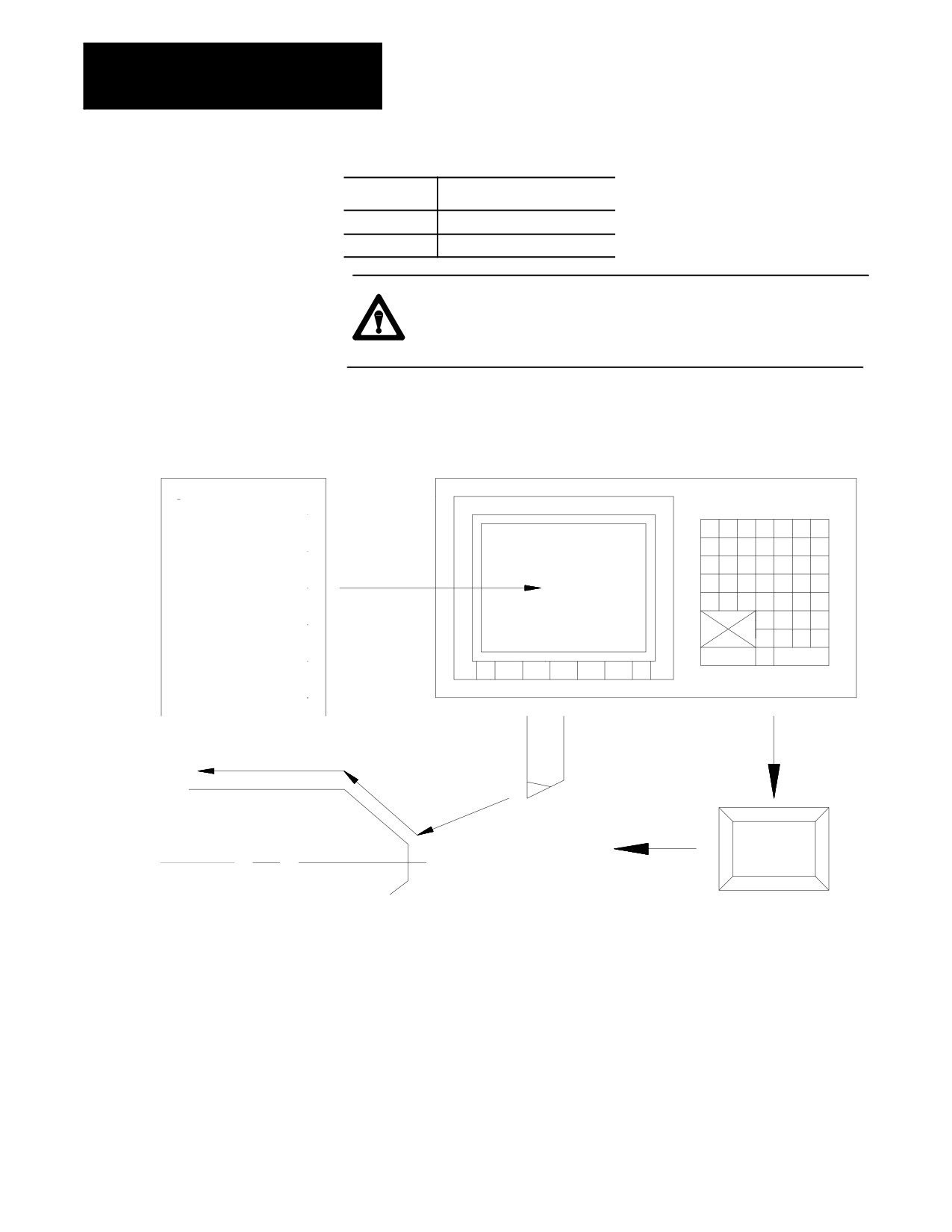
Figure 7.4
Automatic Mode
0
12345
S_____ M _____
G92 X ____ Z ____
D _________
G00_________
G01 F_______
CUTTING TOOL
CYCLE
START
WORK PIECE
Execution of a part program continues until the control encounters an M02
or M30. If the control does not encounter an M02 or M30 at the end of a
program, the error message “MISSING M02/M30” appears.
You can stop execution at any time by using any of the methods described
on page 7-6 or by pressing the <EMERGENCY STOP> button.
7-24
Chapter 7
Running a Program
7.8
Use the program recover feature to resume a program that was executing
and was interrupted by some means such as a control reset, E-Stop, or even
Interrupted Program
power failure in some cases. This feature will scan the program as it
Recover {RESTRT PRGRAM}
searches for the interrupted block and from within the search area:
send to PAL the last programmed modal G--codes from each modal
group.
send to PAL the last programmed modal M--codes from each modal
group and set its associated PAL strobe (non--modal codes including
user--defined M--codes are not sent to PAL).
send to PAL the last programmed T code and set its associated PAL
strobe
send to PAL the last programmed auxiliary function code (B--word) and
set its associated PAL strobe
send to PAL the last programmed spindle commanded speed and set its
associated PAL strobe
resolve paramacro equations and assign paramacro variable values (note
on dual process systems shared paramacro variables can be different
than expected depending on the state of the part program in the other
process, also equations that use PAL paramacro variables may also
evaluate differently since no paramacro interaction with PAL occurs
during a search operation).
establishes any work coordinate system, including all offsets and
rotations to the work coordinate system.
Important: Incremental moves that occur during a interrupted program
recover operation, are always referenced from the last known absolute
position in the part program. If no absolute position is specified in the
searched part program blocks, the control will use the current axis position
as the start point for incremental moves.
Unless Cutter Compensation is active, when a program recover is
performed, the control automatically returns the program to the beginning
of the block that was interrupted. In the case of power failure, the control
will even reselect the program that was active prior to the interruption.
When a program recover is performed the control automatically returns the
program to the beginning of the block that was interrupted. In the case of
power fail the control will even reselect the program as active.
7-25
Chapter 7
Running a Program
CAUTION: When a program recover is performed the control
automatically returns the program to the beginning of the block
that was originally interrupted. The beginning of the block is
probably not the point that axis motion was interrupted. For
absolute linear moves this causes no problem if the tool is still
somewhere along the path of the block that program execution
was interrupted while cutting. In incremental or circular mode
however, if the cutting tool is still located at the point that
program execution was interrupted a restart may damage the
part. If a program recover operation is performed in
incremental mode it is important that the cutting tool be at the
location that the interrupted program block began, not the
location that the program was interrupted at.
This feature may be used to search into any subprogram or paramacro that
may be contained in the main program also.
WARNING: It is the responsibility of the system installers PAL
application to make sure proper activation of all necessary
machine functions has occurred before allowing a interrupted
program to continue. You should verify that all machine
functions are in the correct state before pressing
<CYCLE START>.
Important: The interrupted program recover feature will not:
send PAL nonmodal M--codes including user--defined groups 0 -- 3,
group 4, group 5, and group 6 M--codes.
on dual process systems, halt execution for synchronization codes.
read from or write paramacro variables to PAL
on dual process systems, shared paramacro variables between processes
may not be evaluated as desired depending on the status of the other
process.
send to PAL gear change requests based on spindle speed
7-26
Chapter 7
Running a Program
To perform a program restore operation after automatic program execution
has been interrupted follow these steps:
1.
Press the {PRGRAM MANAGE} softkey.
(softkey level 1)
PRGRAM
OFFSET
MACRO
QUICK
SYSTEM
MANAGE
PARAM
CHECK
SUPORT
FRONT
ERROR
PASS-
SWITCH
PANEL
MESAGE
WORD
LANG
Important: DO NOT SELECT A PROGRAM AS AN ACTIVE
PROGRAM. Do not disable the currently active program (if any). If a
program is reselected as active or disabled by the operator the program
restore feature is canceled.
2.
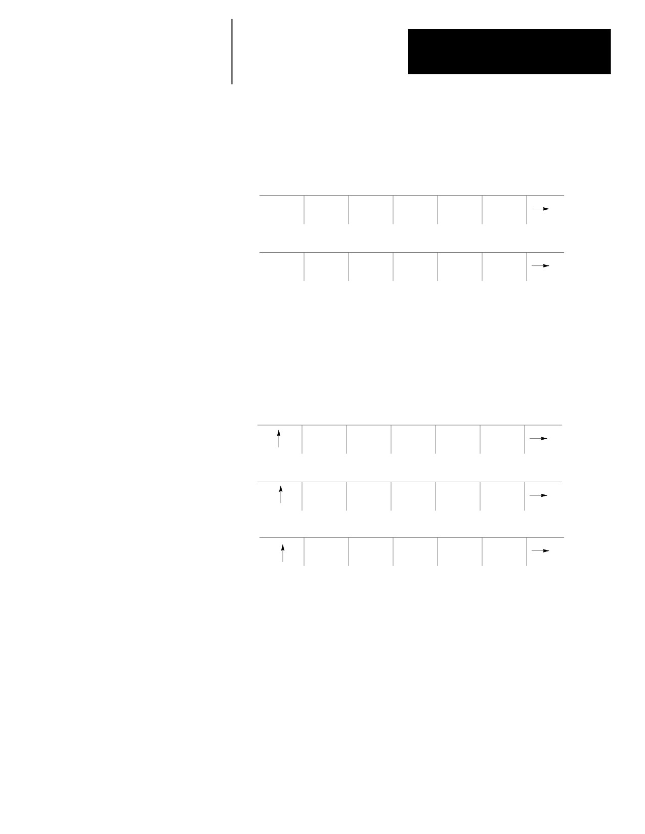
Press the {RESTRT PRGRAM} softkey. The control automatically
re-selects the interrupted program if it was disabled by the control
when power was lost.
(softkey level 2)
ACTIVE
EDIT
RESTRT
DISPLY
COPY
PRGRAM
PRGRAM
PRGRAM
PRGRAM
PRGRAM
VERFY
PRGRAM
DELETE
RENAME
INPUT
PRGRAM
COMENT
PRGRAM
PRGRAM
DEVICE
REFORM
MEMORY
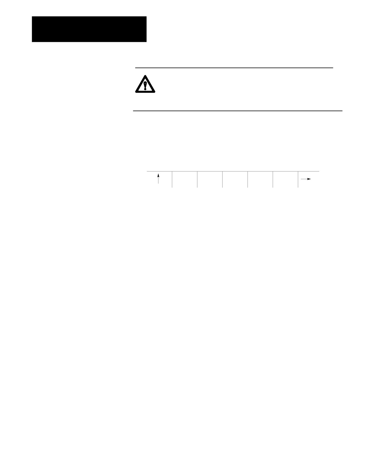
3.
To automatically search for the block in the current program that was
interrupted press the {EXEC} softkey.
The control will locate an @ symbol to the left of the block
immediately before the block that automatic execution was
interrupted at.
If this is not the block to begin execution from, press the {QUIT}
softkey. The program restore feature will be aborted.
7-27
Chapter 7
Running a Program
CAUTION: When you exit a program restart operation (search
with memory), M- and S-codes are sent to PAL. If, during
normal execution, that program activated a spindle,
mid-program start may also start it.
4.
Press the {EXIT} softkey if the block selected is the block to begin
program execution from. If it not the desired block, it will be
necessary to disable the program or perform a search with memory
operation to locate the desired block manually.
(softkey level 3)
EXEC
QUIT
EXIT
When the {CYCLE START} button is pressed the control resumes program
execution from the block selected with the program re-start feature.
7.9
Use the jog retract feature to allow for inspection or change of the cutting
tool during automatic program execution. It allows the cutting tool to be
Jog Retract
jogged from the workpiece in multiple steps, and then returned to the
workpiece automatically by having the control retrace the jogging steps
that were used.
The control remembers up to 15 jog retract moves. The actual number of
moves retained can vary from 0 to 15 as determined by an AMP parameter
set by your system installer. The control returns the tool along the jog
retract path at a feedrate specified in AMP.
Important: If the same axis is used in succession during a jog retract
operation, the control assumes that only one jog retract move has been
executed on that axis.
Only simple single axes jog moves can be performed during the jog retract
function. You cannot perform multiple axis jogs, arbitrary angle jogs and
jogging offset.
Tool offsets can be changed at any time during jog retract. See page
NO TAG. The control does not make these offsets active until the
execution of the first block after the tool has been returned from jog
retract.
7-28
Chapter 7
Running a Program
CAUTION: If the Jog Retract function is deactivated during its
execution (performing a control reset, E-Stop, etc.), attempting
to return the tool by pressing <CYCLE START> can cause the Jog
Retract function to abort. The program returns to the start point
of jog retract along a linear path. In the event that Jog Retract is
deactivated during execution, we recommend that the cutting
tool be jogged to the point from which jog retract was started
prior to pressing <CYCLE START> to avoid possible part or tool
damage.
To perform a jog retract operation:
1.
Press the <CYCLE STOP> or activate <SINGLE BLOCK> feature button
to stop program execution.
2.
Press the <JOG RETRACT> button. The light inside the button turns on
to indicate that the function is active.
3.
Move the cutting tool from the workpiece using either continuous
jog, incremental jog, or HPG jog operations (see page 4-1 for
jogging information.)
4.
Inspect and change the tool or tool offset as desired. Details on how
to do this are on page NO TAG.
5.
After completing the desired inspection or tool change, press the
<CYCLE START> button. Any tool offset changes you have made
become active when the cycle start is requested. The tool returns to
the location where jog retract began, following the same path used
when you jogged the tool away from the work piece (+ or -- any new
tool offset values).
You can press <CYCLE STOP> during the tools automatic return to the
jog retract start position. When this is done, the tool can be retracted
from this point using jog moves and the control adds these moves to
any remaining jog retract steps that have not yet been returned.
6.
Once the cutting tool is fully returned from a jog retract operation, the
control continues on in the part program unless in single block mode.
If in single block mode, the control goes to the cycle stop state when
the return from jog retract is completed. Press <CYCLE START >
again to resume program execution.
7-29
Chapter 7
Running a Program
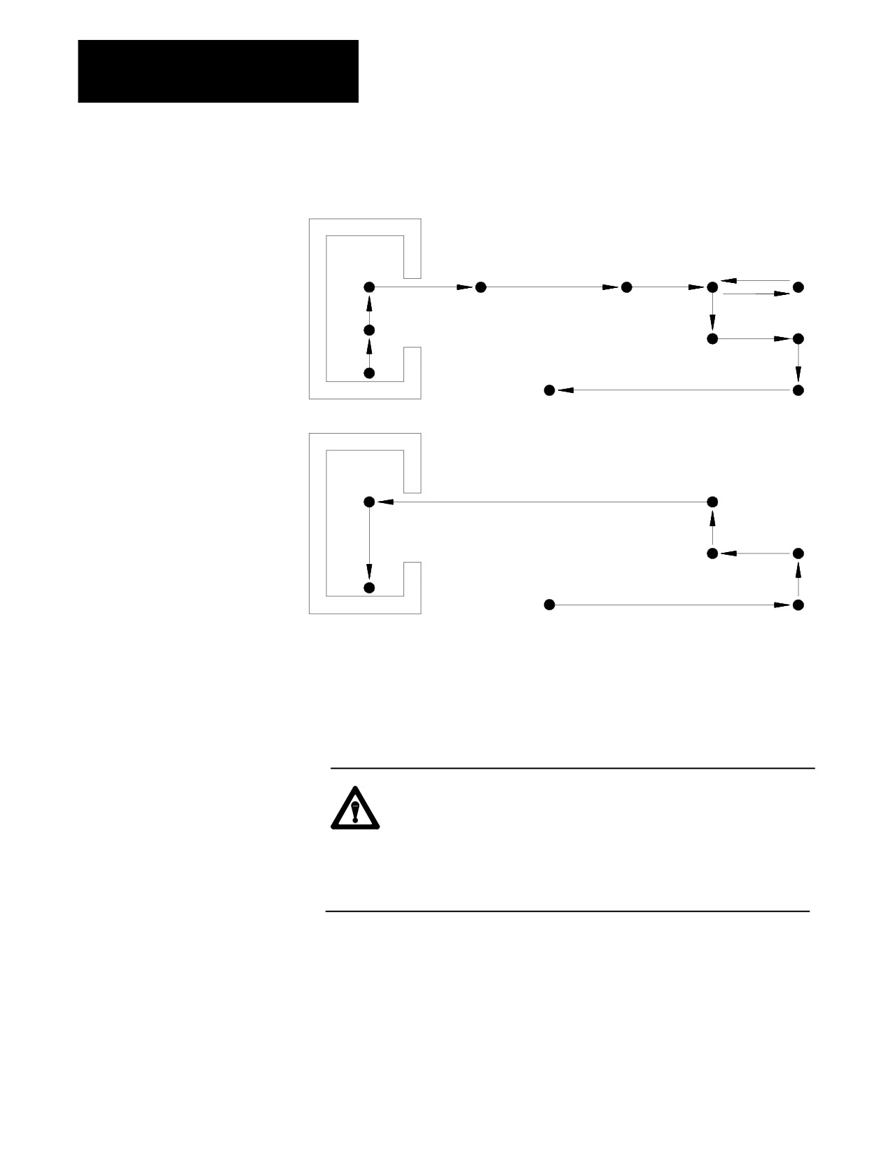
Figure 7.5
Jog Retract Operation
Jog retract exit moves
Jog retract return moves
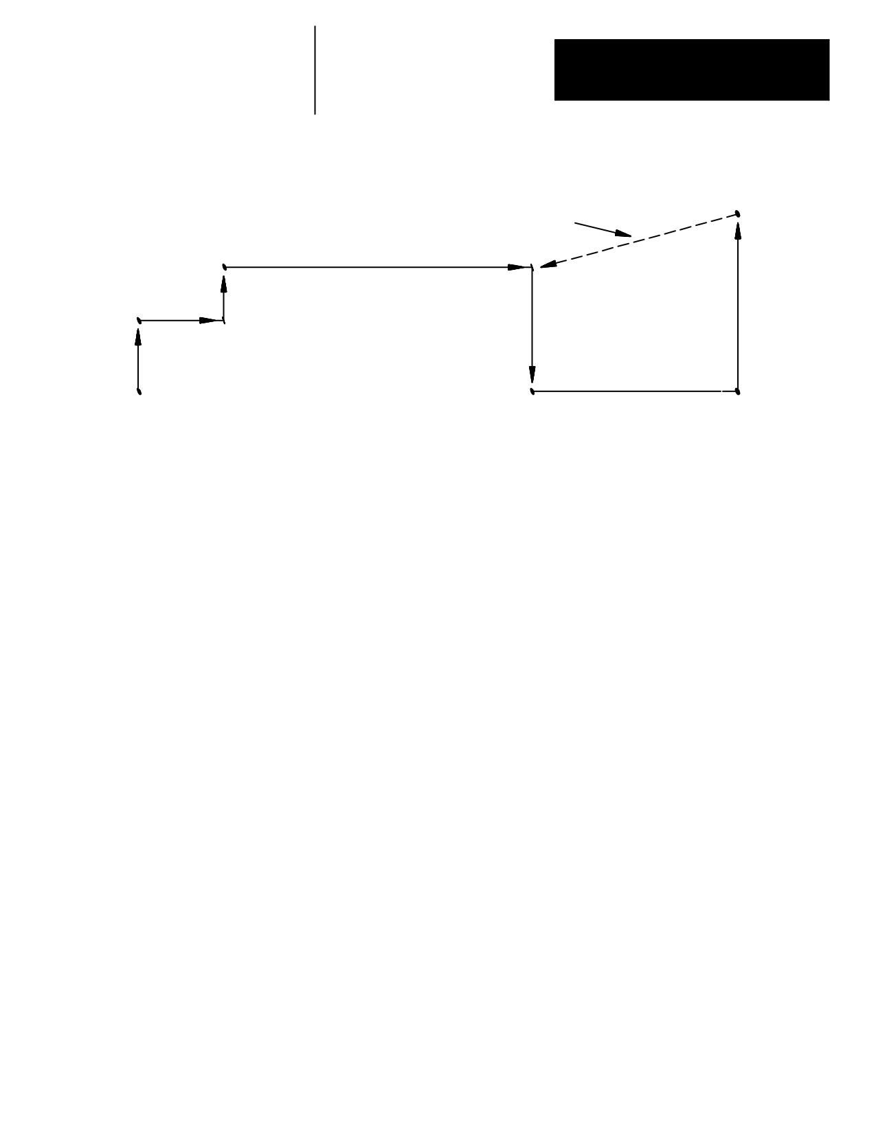
In Figure 7.5 the control only recognized 6 jog moves upon returning
instead of the actual 11 moves that were made to retract the tool. This is
because the jog retract feature records consecutive jog moves on the same
axis as one move.
CAUTION: If the number of jog retract moves performed
exceeds the maximum allowed number set in AMP, the control
moves the cutting tool directly from the final point of jog retract
to the last remembered jog retract point along a straight line
when <CYCLE START> is pressed. Then the tool is returned in
the normal jog retract fashion.
7-30
Chapter 7
Running a Program
Figure 7.6
Jog Retract Moves that Exceed the Maximum Allowed in AMP
Return path
4
3
2
7
5
1
6
Figure 7.6 emphasizes the possible problems that can result from
exceeding the maximum allowed jog retract moves. In this example, the
number of allowed moves set in AMP is four.
When you press the cycle start button at the end of the 7th jog move, the
control ignores moves 5, 6, and 7 and takes the shortest path to the
endpoint of exit move 4. This is because the maximum number of jog
retract moves set in AMP has been exceeded. After reaching the endpoint
of move 4, the control continues the jog retract return operation as normal.
If the jogging moves of 5, 6, and 7 were intended to avoid a protrusion
during the jog retract, a collision could result when returning the tool.
7.10
The block retrace function allows the operator to retrace the motion created
Block Retrace
by up to 15 consecutive part program blocks. The actual number of retrace
blocks allowed is set by your system installer in AMP, and can vary from 1
to 15.
Important: For maximum control efficiency when executing programs,
we recommend that the maximum number of allowable block retraces is
set as small as possible for the current machine application. This is
because the number of allowable Block Retraces directly affects the
controls block look ahead operation.
This function can only be enabled when the control is in cycle stop or
cycle suspend state, and it is ignored if the control has already executed an
M02 or M30 end of program.
7-31
Chapter 7
Running a Program
To perform a block retrace operation:
1.
Press the <CYCLE STOP> or activate the <SINGLE BLOCK> feature
button to stop program execution.
2.
Press the <BLOCK RETRACE> button.
After you press the <BLOCK RETRACE> button, the control retraces the block
that was being executed when the cycle stop occurred or retraces the block
just completed if you press the single block button, provided that the block
is a legal block for retrace.
While the block retrace function is active, the light in the
<BLOCK RETRACE> button is on. The block that was shown as active when
the block retrace was activated still appears as the currently active block in
the program display area during the entire use of the block retrace function.
Important: If you use the <CYCLE STOP> button to halt execution to begin
a block retrace, the control re-executes the portion of the block that has
been executed. For example, if the block requests an axis move of 20 mm
and the axis has moved 12 mm when you press the <CYCLE STOP> button, a
block retrace reverses the axis direction 12 mm.
All retraced blocks are executed at the feedrate programmed for that block
though this may be modified by the use of the <FEEDRATE OVERRIDE>
switch. See chapter 18.
Press the <CYCLE START> button at any time during a block retrace to
return the cutting tool to normal forward execution. Program execution
returns to the normal forward direction from the currently retraced block.
The control executes the retraced blocks in normal order until the tool is
positioned at the start point of block retrace. From this point it continues
program execution in a normal fashion unless <SINGLE BLOCK> is active.
If <SINGLE BLOCK> is active, the control halts execution when the return
from block retract is complete.
While block retrace is active, the control disables all jog features with the
exception of <JOG RETRACT>. See page 7-17. MDI is not available to
insert blocks during a block retrace operation.
7-32
Chapter 7
Running a Program
The block retrace function is unable to retrace any of these blocks and an
attempt to do so results in an error message:
Threading
Tapping
Boring
Inch/Metric changes (unit conversion)
A block that commands a tool change operation
A block that commands a change in the coordinate system
Any block that is followed by a Manual Jog Move except a Jog Retract
The number of blocks retraced is already equal to the maximum number
of retraceable blocks as determined in AMP
Certain Paramacro Parameter Assignments
Interrupt Macros
Any multiprogramming synchronization block (M100 -- M199)
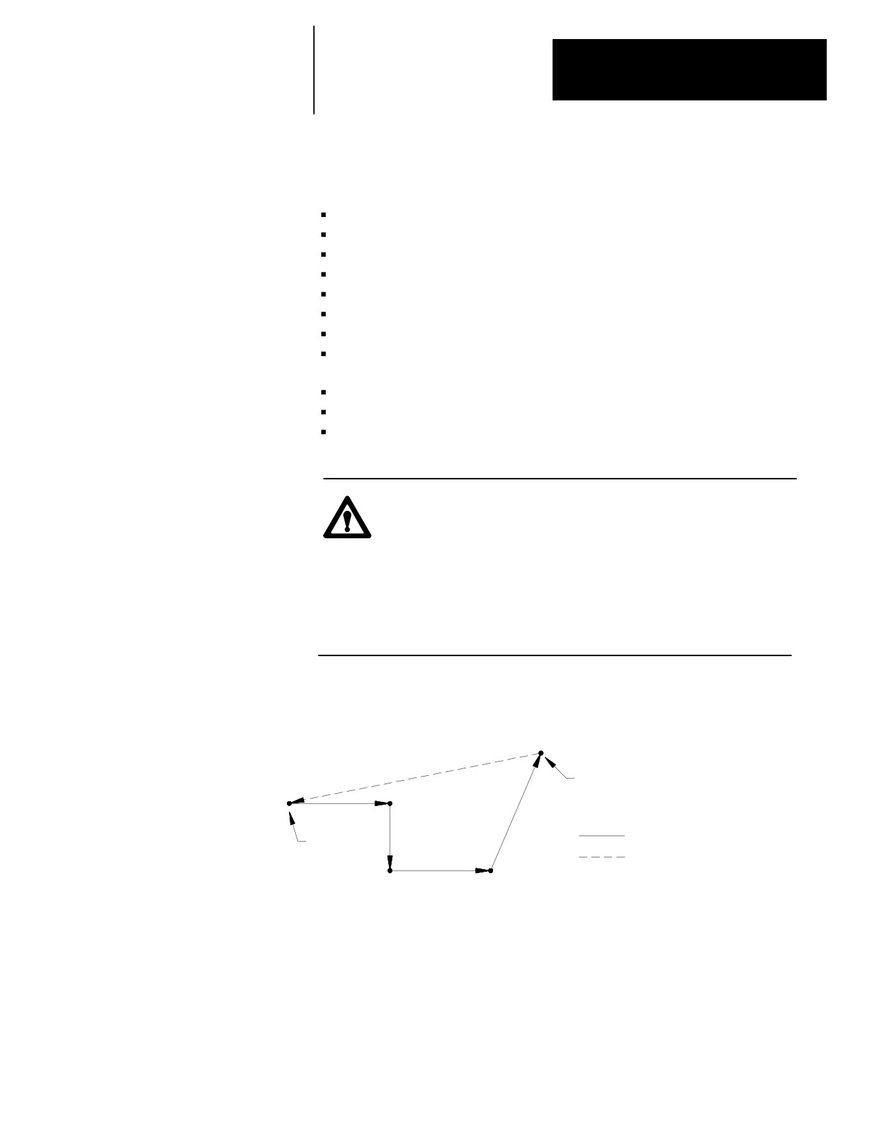
CAUTION: If the block retrace function is deactivated during
its execution (performing a control reset, E-Stop, etc.),
attempting to return the tool by pressing cycle start can cause an
undesired return path. The tool returns to the start point of
block retrace along a linear path. This is most likely not the
retracted path. To avoid possible part or tool damage, we
recommend that the cutting tool be jogged to the point from
which block retrace was started prior to pressing cycle start.
Figure 7.7
Pressing Cycle Start When Retract Path is Lost
Block retrace
aborted here
Normal block retrace path
Start point
of block
Return path taken when
retrace
cycle start is pressed after
block retrace is aborted
END OF CHAPTER
7-33