9/Series CNC Lathe. Operation and Programming Manual - page 5
Chapter 5
Editing Programs On Line
4.
Select the blocks to renumber. There are two choices:
If you want to assign sequence numbers to:
Press:
all blocks from the beginning of the part program
{ALL}
only the block that already have sequence numbers
{ONLY N}
Important: Any sequence numbers in a block that are referenced in the
current program by a paramacro “GOTO” or “WHILE” or by a roughing
cycle are also renumbered. In order to maintain proper program execution,
you must manually alter the “GOTO,” “WHILE,” or roughing cycle blocks
target block sequence number.
5.2.6
You can merge a complete part program within another part program while
one of the programs is in the edit mode. To merge part programs follow
Merging Part Programs
these steps:
{MERGE PRGRAM}
1.
Move the cursor in the program display area just after the location
that another program is to be inserted. The merged program will be
inserted to the left of the cursor with each end of block statement
creating a new line.
2.
Press the continue softkey {fi } to change the softkey functions.
3.
Press the {MERGE PRGRAM} softkey. The prompt “MERGE
PRGRAM:” will appear on the input line of the screen.
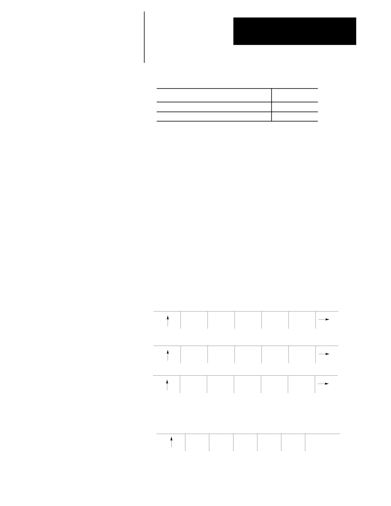
(softkey level 3)
MODIFY
BLOCK
BLOCK
DELETE
EXIT
INSERT
DELETE
TRUNC
CH/WRD
EDITOR
STRING
RENUM
MERGE
QUICK
CHAR/
SEARCH
PRGRAM
PRGRAM
VIEW
WORD
DIGITZ
E
4.
Key-in the program name of the part program to insert, then press
either the [TRANSMIT] key or the {EXEC} softkey.
(softkey level 1)
EXEC
5-15
Chapter 5
Editing Programs On Line
5.2.7
When you edit a program, all changes and additions that you make are
saved immediately in the control’s memory. You don’t execute a formal
Exiting Edit Mode
“save” command.
Important: You cannot quit, abandon or abort an edit session and restore
the original version of the program. For that reason, we recommend that
you copy the program (see page 5-4 ) prior to editing.
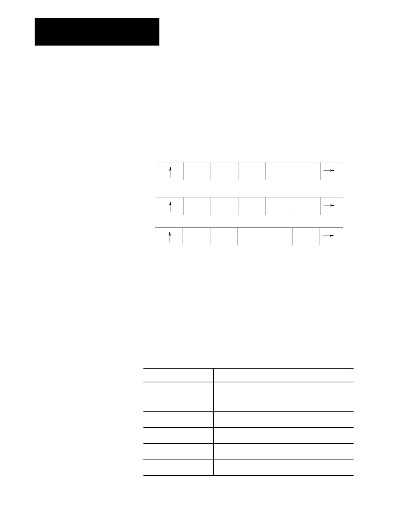
To exit the edit mode, press the {EXIT EDITOR} softkey.
(softkey level 3)
MODIFY
BLOCK
BLOCK
DELETE
EXIT
INSERT
DELETE
TRUNC
CH/WRD
EDITOR
STRING
RENUM
MERGE
QUICK
CHAR/
SEARCH
PRGRAM
PRGRAM
VIEW
WORD
DIGITZ
E
Important: Do not press the Exit {›} softkey to leave a program. You
must use {EXIT EDITOR} softkey. Exiting with the Exit {›} softkey
(shown on the CRT as an up-arrow) causes the program editor to remain
open for that program. This disables the program to from being executed,
and it also does not allow any other program to be selected for editing.
5.3
The QuickView features display sample patterns or the G-code prompts to
help you write part programs. By keying in data corresponding to
Programming Aids
prompted messages, the control automatically generates the required
{QUICK VIEW}
block(s) to insert into an existing part program. The QuickView features
give you access to:
QuickView feature:
Description:
QuickPath Plus Prompts
a selection of commonly used sample patterns representing a
series of machining steps with prompts for the necessary
words to program it using QuickPath Plus (see chapter 15 for
details on QuickPath Plus
G-code Prompting
a selection of the more commonly used G-codes with prompts
for the necessary words used in its programming.
Drilling Fixed Cycle Prompting
a selection of the more commonly used for drilling fixed cycles
with prompts for the necessary words used in its programming
Turning Fixed Cycle
a selection of the more commonly used for turning fixed cycles
Prompting
with prompts for the necessary words used in its programming
Plane Select
a selection of the planes in which the different QuickView are
programmed
5-16
Chapter 5
Editing Programs On Line
How to Select QuickView Features
Use these steps to select the QuickView features:
1.
Select a program for editing as described on page 5-2 .
2.
From the edit menu, press the {QUICK VIEW} softkey.
The softkey functions change to those indicated below:
(softkey level 4)
QPATH+
GCODE
DRILL
LATHE
PLANE
PROMPT
PROMPT
PROMPT
PROMPT
SELECT
Important: If your system is a dual-process lathe, you must select the
process to be prompted by QuickView. Refer to page 30-4 for details on
selecting this QuickView process.
Axis Selection
The selection of the axes that can be programmed using QuickView is
determined by the type of QuickView prompt you are using. The two
factors the control uses to determine the axes for QuickView are based on
if the QuickView prompt is for a planar G--code or a non-planar G code.
Planar G--codes -- Planar G codes are any feature that is plane dependant (such as
G02, G41, Cycles, etc...). The first two axes are selected with the
{PLANE SELECT} QuickView softkey discussed on page 5-27. The third axis
displayed is the axis not in the current plane but in both of the other planes
defined. For example if G17=XY, G18=ZX , G19=YZ and G18 is selected as the
QuickView plane than Y would be the third axis since it is in both G17 and G19
planes but not in the G18 plane. If there is no common axis between these two
planes then the next axis defined in the process that is not already in the
QuickView plane is used.
Non-Planar G--codes - Non-planar G codes are any feature that is not plane
dependant (such as G01, G04, G92, etc...). The axes used for QuickView
prompts for these features are independent of the QuickView plane you have
selected. The control uses the first three axes configured in the current process.
Important: Two digit axis names are not compatible with the QuickView
feature (typically only used on systems with more than 9 axes and consist
of a dollar sign “$” followed by a letter). When an attempt is made to
display one of these axis names on a QuickView prompt, the axis name is
displayed as a $ only. QuickView can not be used to create part program
blocks with $ axis names.
On QuickView screens that display more axis then currently configured in
the system (as configured in AMP), the graphics and prompts will display
asterisks for the un-available axes names. No data can be entered on these
prompts where the asterisks is present.
5-17
Chapter 5
Editing Programs On Line
5.3.1
With the QuickView functions and the QuickPath Plus section, you can use
dimensions from part drawings to create a part program. The sample
Using {QPATH+ PROMPT}
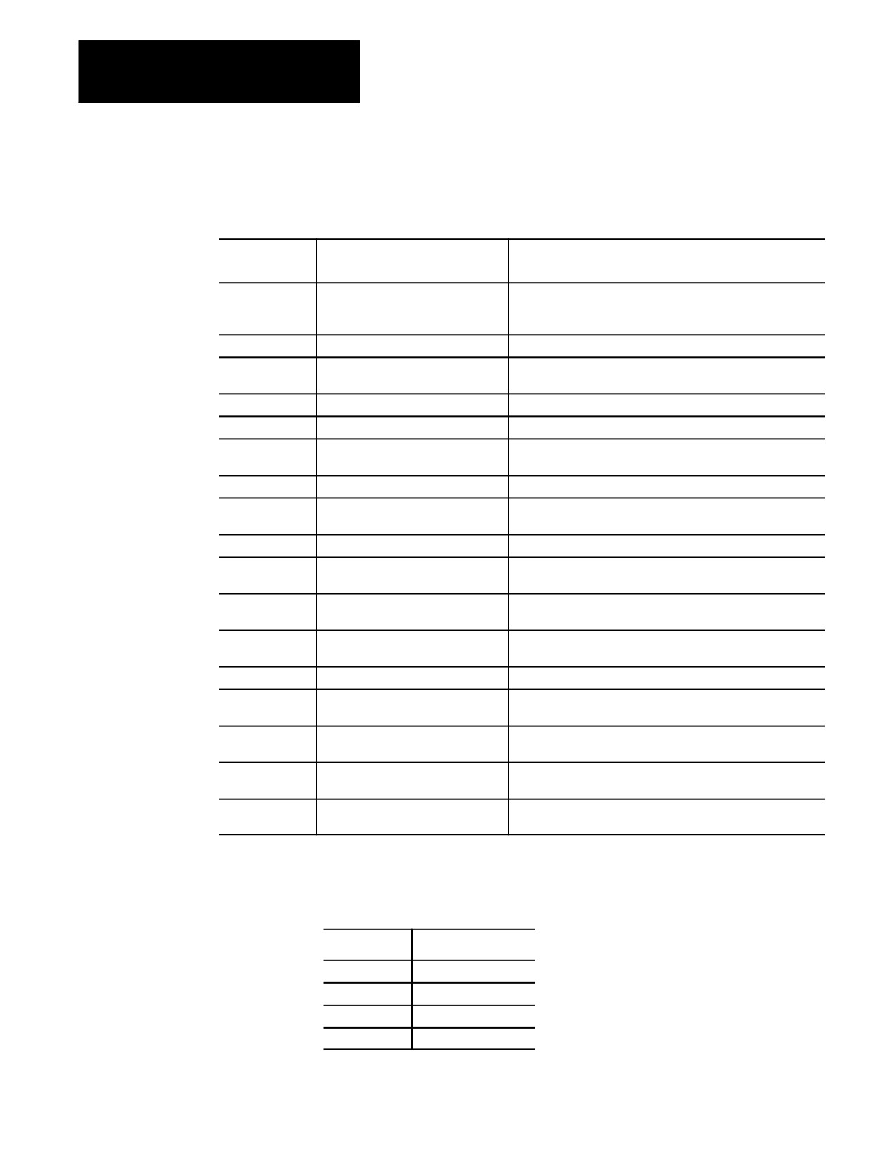
patterns available with the QuickPath Plus prompts are summarized below:
Sample Patterns
Use this
When you program this geometry:
And you know the:
pattern:
{CIR
arc to the line
arc radius and the taper angle of a line
ANG PT}
R (Radius), ,A (Angle in degrees), G (02 for clockwise 03 for
counterclockwise) and the coordinates of the end-point.
{CIR CIR}
an arc to another arc
coordinates of the arc centers
{ANG
the line to an arc
taper angle of a line and the arc radius
CIR PT}
{1ANG PT}
the definition of a line
taper angle and either of the end-point coordinate values
{2ANG 1PT}
defining two successive tapered lines
angles of two tapered lines
{2ANG
two lines joined by an arc.
angles of two tapered lines
1PT R}
{2PT R}
two lines joined by an arc.
intersection point of two lines
{2ANG
two lines joined by a chamfer.
angles of two tapered lines
1PT C}
{2PT C}
two lines joined by a chamfer.
intersection point of two lines
{2ANG
three lines joined by and tangent to
taper angles of two tapered lines and two arc radii
2PT R}
two arcs
{3PT R}
three lines joined by an arc between
two intersection points
two adjacent lines
{2ANG
three lines joined by chamfers
taper angles of two lines and one intersection point
2PT C}
{3PT C}
lines joined by chamfers.
two intersection points are known for defining three
{2ANG
three lines joined by an arc and a
taper angles of two tapered lines and one intersection point
2PT RC}
chamfer.
{3PT RC}
three lines joined by an arc and a
two intersection points
chamfer
{2ANG
three lines joined by an arc and a
taper angles of two lines and one intersection point
2PT CR}
chamfer
{3PT CR}
three lines joined by an arc and a
two intersection points
chamfer
Angle of a line, corner radius, and chamfer size are often necessary for a
sample pattern in QuickPath Plus prompting. These prompts in QuickPath
Plus prompting refer to these drawing dimensions:
If you see an:
It means:
A
angle
R
corner radius
C
chamfer size
L
length of line
5-18
Chapter 5
Editing Programs On Line
For more information regarding these designations, see chapters 15 and 16.
Your system installer can select a different address for angle A in AMP.
Refer to your system installer’s documentation.
Axis words followed by a (1), (2), or (3) are prompting for the first,
second, or third coordinate position respectively. The location of the axis
word is shown on the drawing accompanying the prompt screen.
Prompts that appear:
Indicate that:
in reverse video
this parameter is optional, and you do not need to enter it
in this block.
with an OR to the left
there are two or more optional parameters for this prompt,
only one of which needs a value assigned to it.
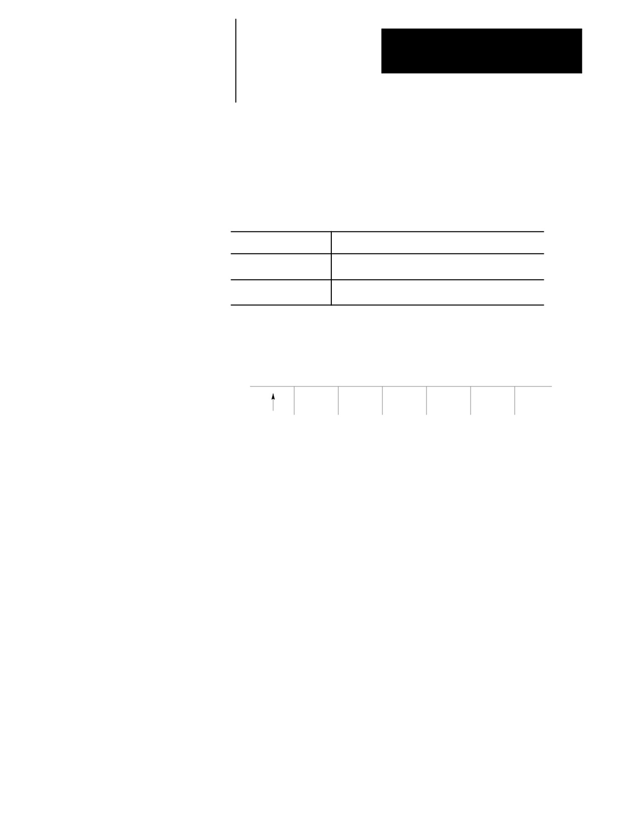
Follow these steps to use the QuickPath Plus QuickView feature:
1.
From the QuickView menu, press the {QPATH+ PROMPT} softkey.
(softkey level 4)
QPATH+
GCODE
DRILL
LATHE
PLANE
PROMPT
PROMPT
PROMPT
PROMPT
SELECT
2.
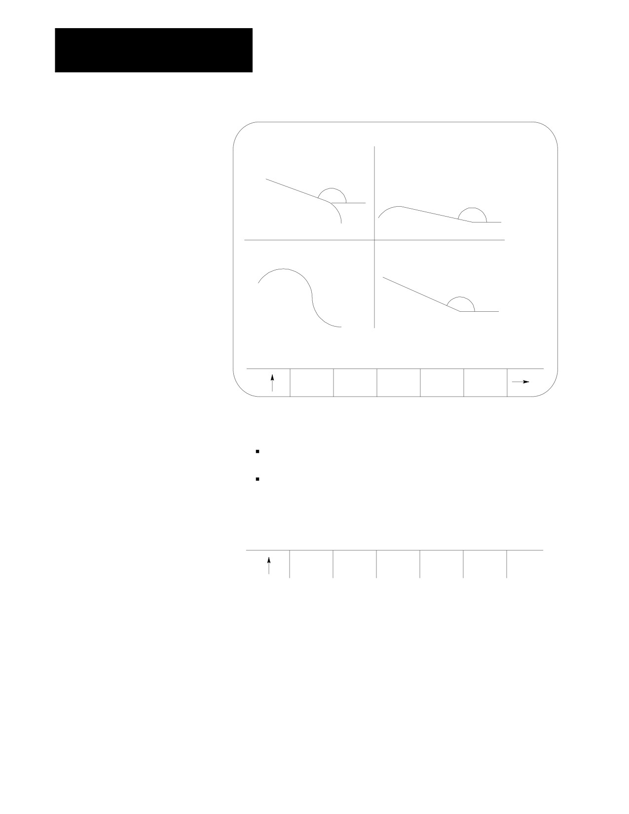
Select a sample pattern matching the part geometry to be
programmed from the previous list of sample patterns, and press the
corresponding softkey.
Change the softkey menu, by pressing the continue softkey {fi }.
Figure 5.3
QuickPath Plus Menu Screen
5-19
Chapter 5
Editing Programs On Line
CIRCLE, ANGLE, POINT
ANGLE, CIRCLE, POINT
CIRCLE , CIRCLE
ANGLE, POINT
QUICKPATH PLUS MENU 1
CIR
CIR
ANG
ANG
ANG PT
CIR
CIR PT
PT
3.
After you select the sample pattern you want, enter values for the
parameters as follows:
Use the up and down cursor keys to select the parameter you want
to change or enter. The selected item appear in reverse video.
Type data you want and press the [TRANSMIT] key.
4.
After all data for the pattern have been entered, store the data by
pressing the {STORE} softkey.
(softkey level 6)
STORE
The control generates the necessary block(s) to create the desired
axis moves. They appear in the input area next to the EDIT: prompt.
You can edit these blocks as described on page 2-37.
5.
To enter the blocks in the program being edited, move the block
cursor in the program display area just past the location where you
want to insert the new blocks, then press the [TRANSMIT] key. Enter
the generated blocks to the left of the cursor.
6.
Press the exit {›} softkey to return to the main edit menu, or press a
different QuickView key for more prompting.
5-20
Chapter 5
Editing Programs On Line
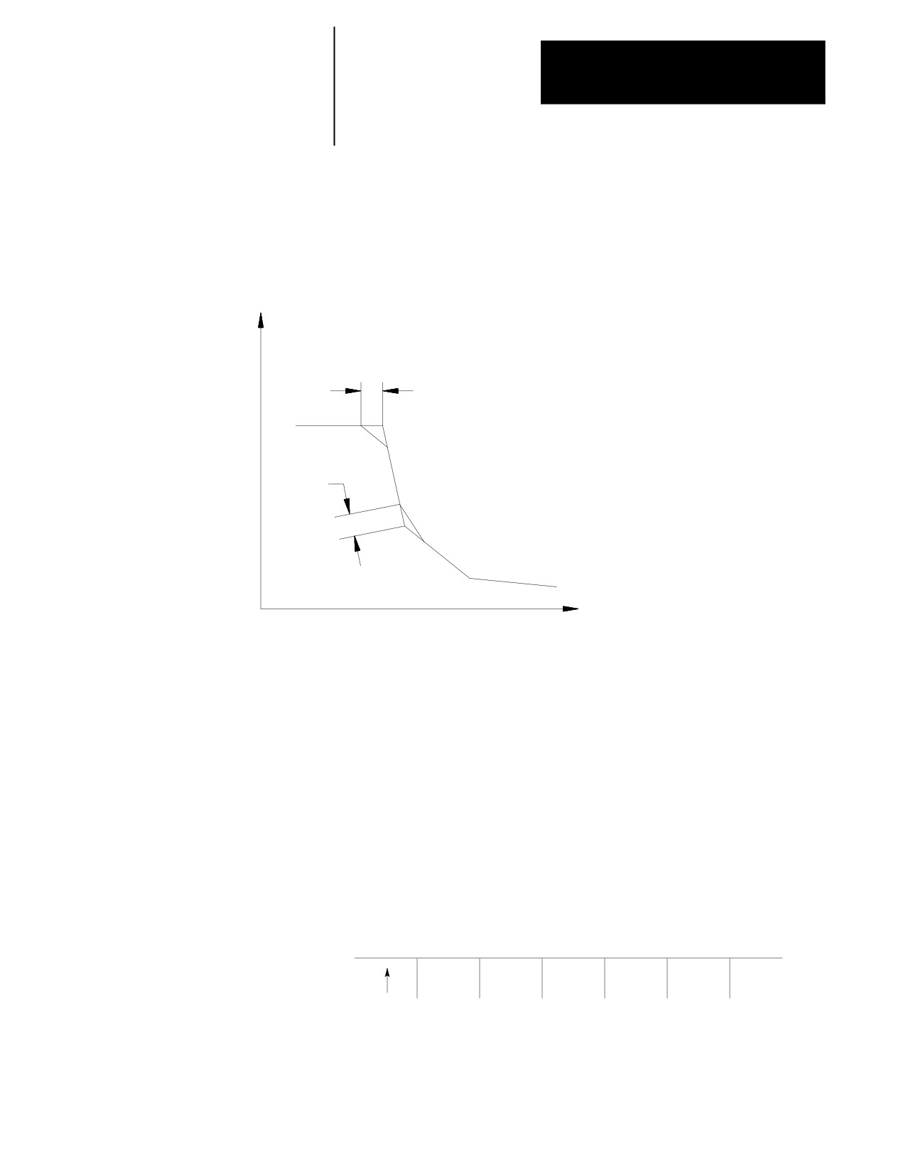
After you press the {3PT C} softkey, the prompt screen for that sample
pattern becomes available. Figure 5.4 is an example of a QuickPath Plus
prompting screen. It shows what data must be entered for that prompted
screen to generate the necessary tool paths correctly.
Figure 5.4
{3PT C}
C1 - Length of the 1st chamfer
C2 - Length of the 2nd chamfer
X1 - End coordinates of the 1st line in the
C
2
current plane
X2 - End coordinates of the 2nd line in
(X2, Z2)
the current plane
(X3, Z3,)
X3 - End coordinates of the 3rd line in
the current plane
Z1 - End coordinates of the 1st line in the
C1
current plane
Z2 - End coordinates of the 2nd line in
the current plane
)
(X1, Z1
Z3 - End coordinates of the 3rd line in
the current plane
5.3.2
G-code format prompting helps you programming different G-codes by
prompting the programmer for the necessary parameters. A graphical
G-code Format Prompting
representation is usually provided to show the programmer a sample of
{G CODE PROMPT}
what the G-code parameters are used for.
Drilling fixed-cycle G-codes are available under fixed-cycle prompting
(see page 5-25), and Turning fixed-cycle G-codes are available under
rough/finish cycle prompting (see page 5-23).
To use the G-code prompting menus:
1.
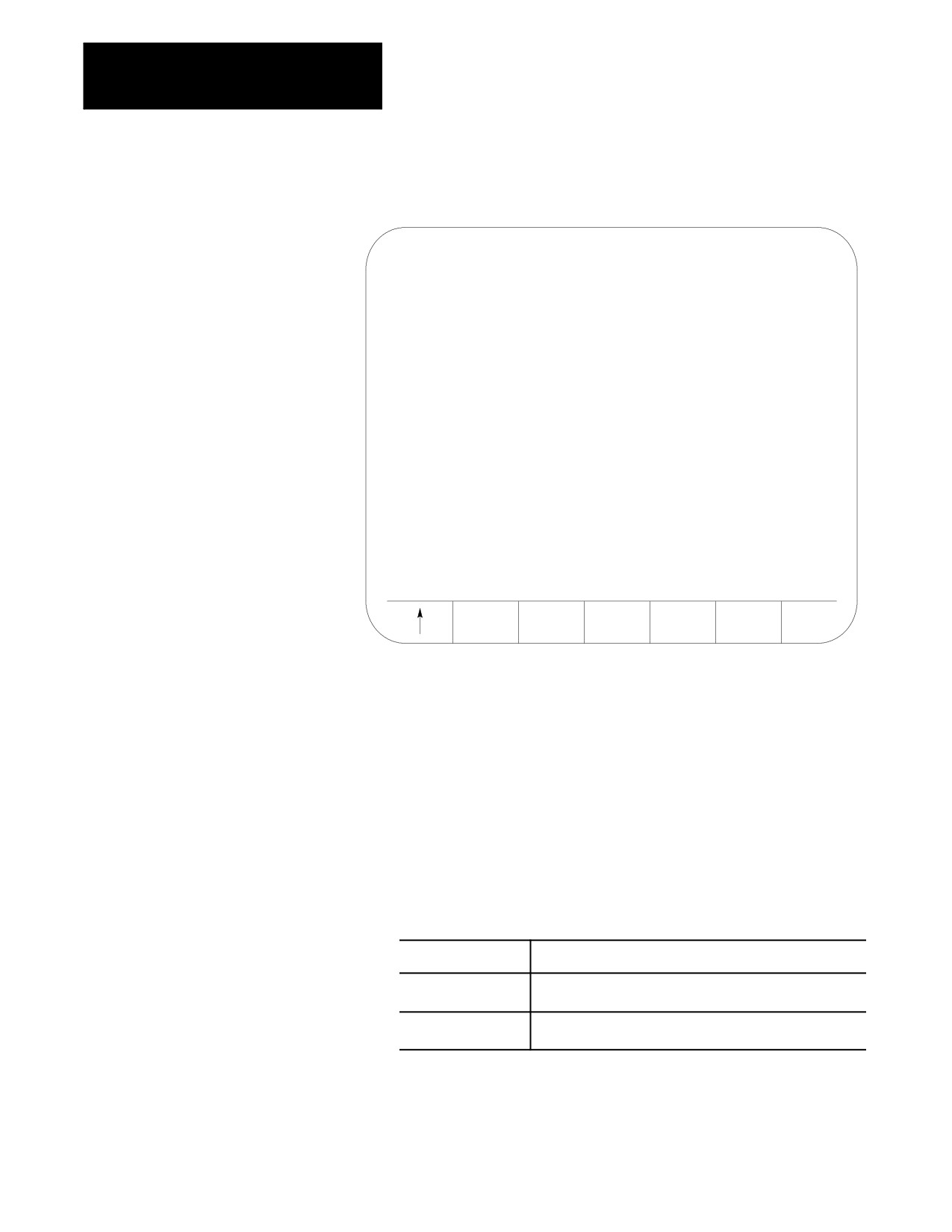
From the QuickView menu, press the {GCODE PROMPT} softkey. The
following G-code prompt select screen becomes available:
(softkey level 4)
QPATH+
GCODE
DRILL
LATHE
PLANE
PROMPT
PROMPT
PROMPT
PROMPT
SELECT
5-21
Chapter 5
Editing Programs On Line
Figure 5.5
G-code Prompt Select Screen
G CODE PROMPTING MENU DISPLAY
PAGE
1 OF
3
G00/01
RAPID/LINEAR INTERPOLATION
G02/03
CIRCULAR/HELICAL INTERPOLATION, CW/CCW
G04
DWELL
G07/G08
RADIUS/DIAMETER PROGRAMMING
G09/61/62/
CUTTING MODE SELECTION
63/64
G10L2
WORK COORDINATE SYSTEM TABLE ENTRY
G10L0&11
TOOL LIFE MANAGEMENT TABLE ENTRY/CANCELLED
G10L10-L13
TOOL OFFSET TABLE ENTRY
G10.1L20
RANDOM TOOL DATA ENTRY
G14.1/14
SCALING ENABLED/DISABLED
G16/15
POLAR COORDINATE PROGRAMMING/CANCELLED
G16.1/15
CYLINDRICAL PROGRAMMING/CANCELLED
G16.2/15
VIRTUAL C AXIS PROGRAMMING/CANCELLED
SELECT
2.
Position the cursor at the desired G-code to prompt by using the up
and down cursor keys. The selected G-code appears in reverse video.
3.
Once you select the correct G-code, press the {SELECT} softkey. The
control displays screen with prompts for that G-code.
4.
Use the up and down cursor keys to select the parameters to be
changed or entered. The selected item appears in reverse video.
Axis words followed by a (1), (2), or (3) are prompting for the first,
second, or third coordinate position respectively. The location of the
first, second, or third axis word is shown on the drawing
accompanying the prompt screen.
Prompts shown:
Indicate that:
in reverse video
this parameter is optional and do not need to be entered in this
block.
with an OR to the left
there are two or more optional parameters for this prompt, only
one of which needs a value assigned.
5.
Type in the desired data for that parameter on the input line of the
CRT, and press the [TRANSMIT] key.
5-22
Chapter 5
Editing Programs On Line
6.
After you enter all data for the G-code, store the data press the
{STORE} softkey.
(softkey level 6)
STORE
CONTNU
The control generates the necessary G-code block. The generated
block displays in the input area next to the EDIT: prompt. You can
edit this block in the input area using the techniques described on
page 2-37.
7.
To enter the blocks in the program being edited, move the block
cursor in the program display area just past the location in the
program where you want to insert the new blocks. Press the
[TRANSMIT] key to enter the generated block in the program to the
left of the cursor.
8.
Press the exit {›} softkey to return to the main edit menu, or press a
different QuickView key for more prompting.
5.3.3
Lathe cycle prompting aids the operator in programming turning cycle
blocks by prompting the programmer for the necessary parameters and
Lathe Cycle Format
giving a graphical representation of the cycle operation.
Prompting
For G-code prompts, see page 5-21; or for drilling fixed cycle prompts, see
page 5-25 .
To use the turning fixed cycle prompting function, follow these steps:
1.
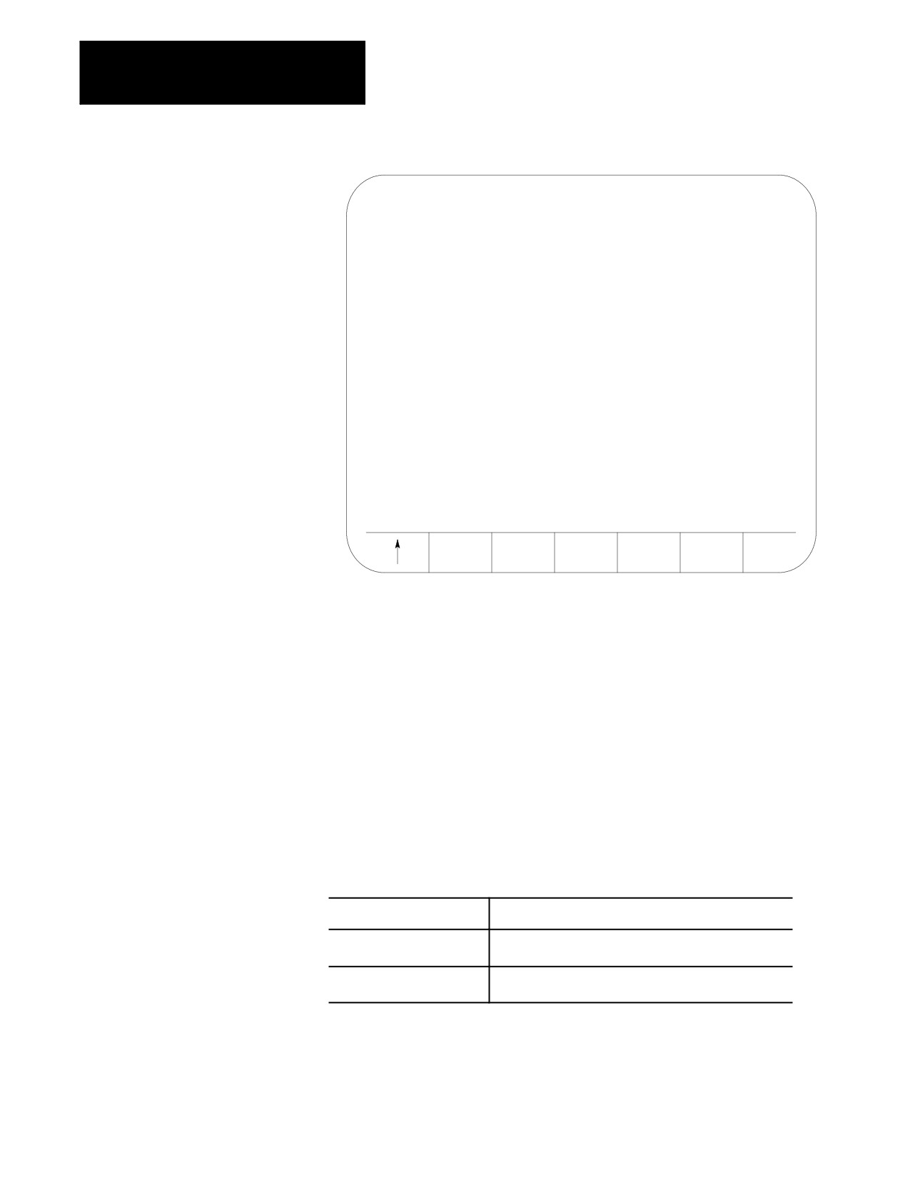
From the QuickView menu, press the {LATHE PROMPT} softkey. The
lathe prompt selection screen shown below becomes available:
(softkey level 4)
QPATH+
GCODE
DRILL
LATHE
PLANE
PROMPT
PROMPT
PROMPT
PROMPT
SELECT
5-23
Chapter 5
Editing Programs On Line
E-STOP
LATHE PROMPT MENU DISPLAY
G20: SINGLE PASS O.D. & I.D. ROUGHING CYCLE
G21: SINGLE PASS THREADING CYCLE
G24: SINGLE PASS ROUGH FACING CYCLE
G72: O.D. & I.D. FINISHING CYCLE
G73: O.D. & I.D. ROUGHING CYCLE
G74: ROUGH FACING CYCLE
G75: CASTING/FORGING ROUGHING CYCLE
G76: FACE GROOVING CYCLE
G77: O.D. & I.D. GROOVING CYCLE
G78: O.D. & I.D. MULTI-PASS THREADING CYCLE
SELECT
2.
Position the cursor at the desired cycle to prompt by using the up and
down cursor keys. The selected G-code cycle appears in reverse
video.
3.
Once you select the correct cycle code, press the {SELECT} softkey.
A screen with prompts for that cycle is displayed along with a
graphical representation of the cycle.
4.
Use the up and down cursor keys to select the parameters to be
changed or entered. The selected parameter appears in reverse video.
Axis words followed by a (1), (2), or (3) are prompting for the first,
second, or third coordinate position respectively. The location of the
first, second, or third axis word appears on the drawing
accompanying the prompt screen.
Prompts that are shown:
Indicate that:
in reverse video
this parameter is optional and does not need to be entered
in this block,
with an OR to the left of the
there are two more optional parameters for this prompt,
prompt
only one of which needs a value assigned.
5.
Type in the data you want for that parameter on the input line of the
CRT, and press the [TRANSMIT] key.
5-24
Chapter 5
Editing Programs On Line
6.
After you enter all data for the G-code, store the data by pressing the
{STORE} softkey.
(softkey level 6)
STORE
The control generates the necessary G-code block. The generated
block is displayed in the input area next to the EDIT: prompt. This
block may be edited in the input area using the techniques described
on page 2-37.
7.
To enter the blocks in the program being edited, move the block
cursor in the program display area just past the location in the
program where you want to insert the new blocks. Press the
[TRANSMIT] key to enter the generated block in the program to the
left of the cursor.
8.
Press the exit {›} softkey to return to the main edit menu, or press a
different QuickView key for more prompting.
For more details on the parameters used in a specific cycle, refer to
chapters 22-25 for details on turning cycle operation and parameters.
5.3.4
Drilling fixed-cycle format prompting aids the programmer by prompting
Drill Cycle Format
for the necessary parameters for the drilling cycle. A graphical
representation illustrating the fixed cycles operation and use of the
Prompting
parameters is also displayed.
For G-code prompts, see page 5-21; and for turning fixed cycle prompts,
see page 5-23.
To use the DRILL fixed-cycle prompting function, follow these steps:
1.
From the QuickView menu, press the {DRILL PROMPT} softkey. The
drill prompt selection screen is displayed.
(softkey level 4)
QPATH+
GCODE
DRILL
LATHE
PLANE
PROMPT
PROMPT
PROMPT
PROMPT
SELECT
5-25
Chapter 5
Editing Programs On Line
DRILL PROMPT MENU DISPLAY
G80: CANCEL OR END FIXED CYCLE
G81: DRILLING CYCLE, NO DWELL/RAPID OUT
G82: DRILLING CYCLE DWELL/RAPID OUT
G83: DEEP HOLE DRILLING CYCLE
G83.1: DEEP HOLE PECK DRILLING CYCLE, DWELL
G84: RIGHT HAND TAPPING CYCLE
G84.1: LEFT HAND TAPPING CYCLE
G85: BORING CYCLE, NO DWELL/FEED OUT
G86: BORING CYCLE SPINDLE STOP, RAPID OUT
G86.1: BORING CYCLE, SPINDLE SHIFT
G87: BACK BORING CYCLE
G88: BORING CYCLE, SPINDLE STOP/MANUAL OUT
G89: BORING CYCLE, DWELL/FEED OUT
SELECT
2.
Position the cursor at the desired cycle to prompt by using the up and
down cursor keys. The selected cycle appears in reverse video.
3.
Once you select the correct cycle code, press the {SELECT} softkey.
A screen with prompts for that cycle appears along with a graphical
representation of the cycle.
4.
Use the up and down cursor keys to select the parameters to be
changed or entered. The selected parameter appears in reverse video.
Axis words followed by a (1), (2), or (3) are prompting for the first,
second, or third coordinate position respectively. The location of the
first, second, or third axis word appears on the drawing
accompanying the prompt screen.
Prompts that are shown:
Indicate that:
in reverse video
this parameter is optional and does not need to be
entered in this block,
with an OR to the left of
there are two more optional parameters for this
the prompt
prompt, only one of which needs a value assigned.
5.
Type in the desired data for that parameter on the input line of the
CRT, and press the [TRANSMIT] key.
6.
After you enter all data for the G-code, store the data by pressing the
{STORE} softkey.
5-26
Chapter 5
Editing Programs On Line
(softkey level 6)
STORE
The control generates the necessary G-code block. The generated
block is displayed in the input area next to the EDIT: prompt. This
block may be edited in the input area using the techniques described
on page 2-37.
7.
To enter the blocks in the program being edited, move the block
cursor in the program display area just past the location in the
program where it is desired to insert the new blocks. Press the
[TRANSMIT] key to enter the generated block in the program to the
left of the cursor.
8.
Press the exit {›} softkey to return to the main edit menu, or press a
different QuickView key for more prompting.
For more details on the parameters used in a specific cycle, see chapter 26
for details on drilling cycle operation and parameters.
5.3.5
Use this feature to select the plane that is used to program the different
QuickView features. This determines what plane is displayed for the
Selecting a QuickView Plane
prompting and their axis names displayed for the prompts. You cannot
select any parallel planes with the QuickView feature; only primary planes
can be used.
Your system installer determines the primary planes established by G17,
G18, and G19 in AMP. See page 13-1 for details on the plane selection.
To set the plane to program in with the QuickView feature, follow these
steps:
1.
From the QuickView menu, press the {PLANE SELECT} softkey.
(softkey level 4)
QPATH+
GCODE
DRILL
LATHE
PLANE
PROMPT
PROMPT
PROMPT
PROMPT
SELECT
The control displays currently selected plane. The right side of the screen
lists the primary and secondary axes for the plane.
“AXIS 1” is the first
axis in the plane (primary axis), and “AXIS 2” is the second axis in the
plane (secondary axis).
5-27
Chapter 5
Editing Programs On Line
2.
Change the plane by pressing the softkey that corresponds to the
plane you want to program in (G17, G18, or G19). Refer to
documentation prepared by your system installer for details on the
planes selected by these G-codes.
The display changes to show the selected plane.
(softkey level 5)
SET
G17
G18
G19
3.
If the plane displayed is the plane you want to program the
QuickView feature in, press the {SET} softkey. All of the prompts for
the QuickView feature are changed to display the newly selected
plane.
Important: This does not select the current operating plane on the control;
it only modifies the plane being programmed in. To change the currently
active plane on the control, you must execute a program block containing a
G17, G18, or G19 block. This block is automatically generated by the
QuickView feature and inserted into the program being edited, so when
this program is executed the correct planes are established.
5.4
The digitize feature allows the programmer to generate blocks in a
program based on the actual position of the cutting tool, rather than by
Digitizing a Program (Teach)
manually typing in positions. The control records actual tool locations and
uses them to generate program blocks.
You can use the digitize feature in any operating mode (auto, manual, or
MDI). It is a function accessed through the regular edit menu which
allows any of the other edit features described on page 5-4 to be used on
blocks that are generated using the digitize feature.
You cannot switch the active process while using the digitize feature. If
you attempt to switch the process, the control displays an error message.
To use the digitize feature, select or create a part program for editing as
described on page 5-4 .
Important: The following description covers the use of softkeys to
perform digitizing. Your system installer can write PAL to allow some
other method of digitizing. Refer to documentation provided by your
system installer.
1.
Select a part program to edit by pressing the {PRGRAM MANAGE}
softkey. Enter a program name, and press the {EDIT PRGRAM}
softkey (see page 5-2 on selecting a program).
5-28
Chapter 5
Editing Programs On Line
2.
From the edit menu, press the {DIGITIZE} softkey.
(softkey level 3)
MODIFY
BLOCK
BLOCK
DELETE
EXIT
INSERT
DELETE
TRUNC
CH/WRD
EDITOR
STRING
RENUM
MERGE
QUICK
CHAR/
SEARCH
PRGRAM
PRGRAM
VIEW
WORD
DIGITZ
E
3.
Use the following methods to position the cutting tool. The cutting
tool should be located at the desired start-point of the new program.
Jog the Axes in manual mode.
Automatically move the axes by executing a part program or MDI
program.
Manually move the axes using any means, as long as the encoder
is still actively recording the tool position (see documentation
prepared by your system installer).
4.
Press the {MODE SELECT} softkey, if you must change any of the
following programming modes while digitizing a program:
(softkey level 4)
LINEAR
CIRCLE
CIRCLE
MODE
3 PNT
TANGNT
SELECT
Inch/metric
Absolute programming/incremental programming
Change planes G17, G18, or G19
Radius programming/Diameter programming
5.
Press any of the softkeys corresponding to the mode you want to
change. The control displays the mode that the next block will be
programmed in, up in the right-hand corner of the screen. The modes
are abbreviated as described in Table 6.A:
(softkey level 5)
INCH/
ABS/
PLANE
DIA/
METRIC
INCR
SELECT
RADIUS
5-29

Chapter 5
Editing Programs On Line
Table 6.A
Changing Programming Modes During Digitizing
Mode Changed To:
Abbreviation
G-code Generated
Softkey
Absolute mode
ABS (Except Lathe A)
G901
{ABS/INCR}
Incremental mode
INC (Except Lathe A)
G911
{ABS/INCR}
Plane selected
G17,G18,G19
G17, G18, G19
{PLANE
SELECT}
Diameter mode
DIA
G08
{DIA/
RADIUS}
Radius mode
RAD
G07
{DIA/
RADIUS}
Inch mode
INCH
G20
{INCH/
METRIC}
Metric mode
METRIC
G21
{INCH/
METRIC}
1 To change from incremental or absolute modes, if using lathe A, the control automatically changes the letters used
to program the axis words to the appropriate letters to generate absolute or incremental.
Each time you press the softkey corresponding to the mode, the G-code
displayed changes. When the desired mode is displayed, exit the mode
select screen by pressing the exit {›} softkey.
This returns the control to softkey level 4. The next generated block has
the necessary G-codes to change the mode inserted at the beginning of the
block.
Important: This does not change the current operating mode of the
control. The control only inserts the blocks to change the operating mode
in the program. The mode does not change unless that block is executed or
unless some other MDI or program block that changes modes is executed.
6.
Determine if the next move is linear or circular.
5-30
Chapter 5
Editing Programs On Line
If the next move is to be linear, press the {LINEAR} softkey
(page 5-31)
If the next move is to be circular:
Press:
If you know:
{CIRCLE 3 PNT}
three points on the arc (see page 6.42)
{CIRCLE TANGNT}
the end-point of the arc and the line that is tangent to the
start-point of the arc
Important: To abort the linear digitize operation, press the exit {›}
softkey at any time before pressing the {STORE END PT} or
{EDIT & STORE} softkeys. The control returns to softkey level 4. Then
select either another digitize feature (by pressing one of the softkeys) or
you can return the control to the regular edit session [as described on page
5-4] by pressing the exit {›} softkey.
5.4.1
The following subsection assumes that steps 1-5 on page 5-28 have been
completed to initiate a digitizing operation.
Linear Digitizing
To digitize a linear move:
1.
Press the {LINEAR} softkey
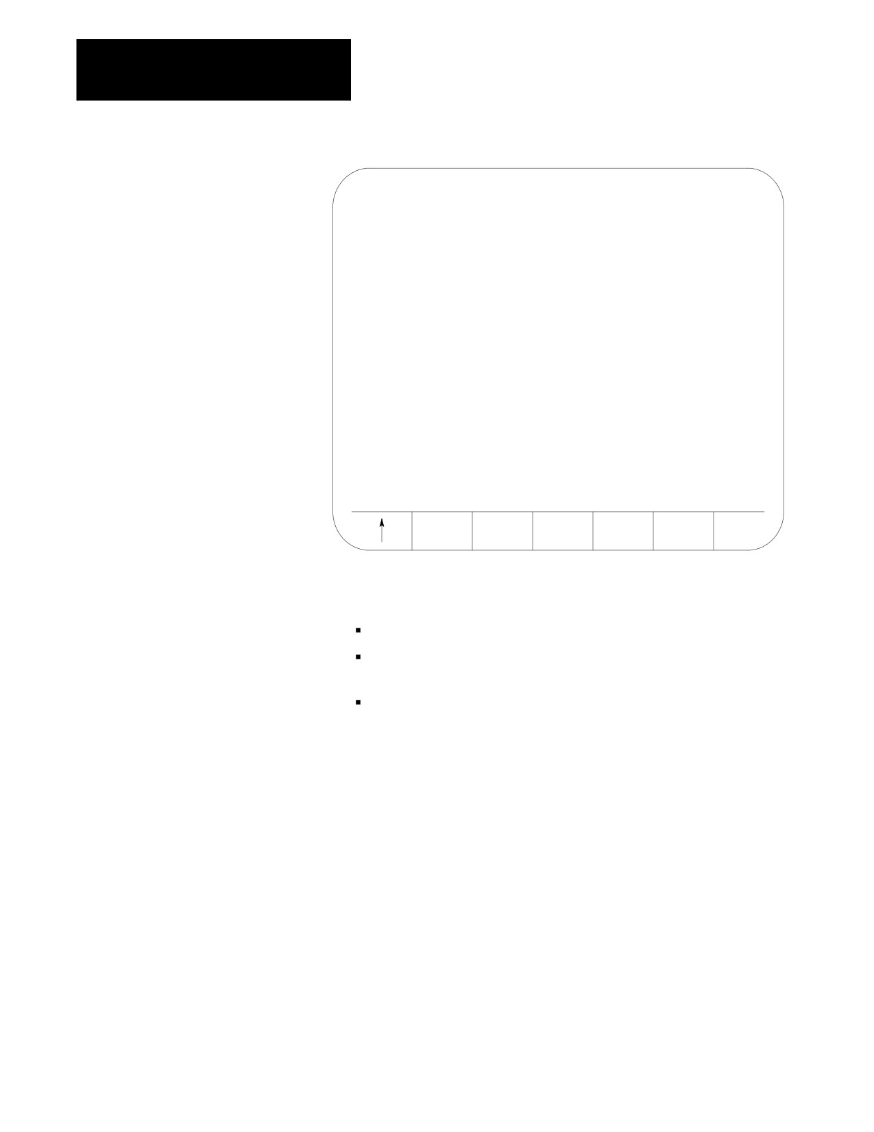
When you press the {LINEAR}, the control sets the current tool
position as the start-point of a linear move. The screen changes to
display the current tool location in large display characters.
5-31
Chapter 5
Editing Programs On Line
DIGITIZE:
E-STOP
TARGET[ MM
]
Z
0.000
R X
0.000
C
359.99
F
0.000 MMPM S
00
STORE
EDIT &
END PT
STORE
2.
Reposition the tool at the desired end-point of the linear move using
any of these methods:
Jog the Axes in manual mode.
Automatically move the axes by executing a part program or MDI
program.
Manually move the axes using any means as long as the encoder is
still actively recording the tool position (see documentation
prepared by the system installer).
3.
After you position the axes at the end-point of the linear move, press
either the {STORE END PT} or the {EDIT & STORE} softkeys. This
records the current tool location as the final position for this digitize
operation.
Digitize screens cannot be displayed as split screens.
5-32
Chapter 5
Editing Programs On Line
5.4.2
The following subsection assumes that steps 1-5 in on page 5-28 have
been completed to initiate a digitizing operation.
Digitizing an Arc (3 Points)
To digitize an arc:
1.
Press the {CIRCLE 3 PNT} softkey if you know 3 points on the circle.
When you press the {CIRCLE 3 PNT} softkey, the control sets the
current tool position as the start point (first point of 3 that is
necessary to describe an arc) of a circular move. The screen changes
to display the current tool location in large display characters.
DIGITIZE:
E-STOP
TARGET[ MM
]
Z
-
0.000
R X
-
0.000
C
-
359.99
F
0.000 MMPM S
00
RECORD
STORE
EDIT &
MID PT
END PT
STORE
2.
Reposition the tool at any point on the arc between the start and the
end point using any of the following methods:
Jog the Axes in manual mode.
Automatically move the axes by executing a part program or MDI
program.
Manually move the axes using any means as long as the encoder is
still actively recording the tool position (see documentation
prepared by the system installer).
5-33
Chapter 5
Editing Programs On Line
3.
After the second point on the arc has been stored reposition the axes
at the end point of the arc. Store this block as a circular block by
pressing either the {STORE END PT} or the {EDIT & STORE} softkeys.
This records the current tool location as the final position for this
digitize operation.
If you press:
It:
{STORE
does not return the control to the program display screen. Pressing
END PT}
this softkey inserts the generated block at whatever location the cursor
was last at and allows the operator to immediately begin entering the
next block using this same digitize feature.
{EDIT &
returns the control to the program display screen. The program block
STORE}
just generated is displayed on the input line of the CRT and may be
edited as discussed in section 2.10. This block is then inserted at the
location of the block cursor when you press the [TRANSMIT] key.
Important: To abort the circular digitize operation, press the exit {›}
softkey at any time before you press the {STORE END PT} or
{EDIT & STORE} softkeys. The control returns to softkey level 4. Then
select either another digitize feature (by pressing one of the softkeys) or
the control can be returned to the regular edit session by pressing the exit
{›} softkey [as described on page 5-4].
5.4.3
The following subsection assumes that steps 1-5 on page 5-28 have been
Digitizing An Arc Tangent at
completed to initiate a digitizing operation.
End Points
To digitize an arc tangent at end points:
1.
Press the {CIRCLE TANGNT} softkeys if the circle is tangent at the
endpoint of the previous cutting path.
When you press the {CIRCLE TANGNT} softkey, the control sets the
current tool position as the start point of a circular move. The screen
displays the current tool location in large display characters.
If the previous block was circular, use a tangent to the end point of
the arc as the tangent point to the following block.
Important: You cannot select the {CIRCLE TANGNT} feature as the first
motion block in a part program. There is no path for the start of the arc to
be tangent to.
5-34
Chapter 5
Editing Programs On Line
Figure 5.6
CIRCLE TANGNT Digitize Screen
DIGITIZE:
E-STOP
TARGET[ MM
Z
-
0.000
R
X
-
0.000
C
-359.99
F
0.000 MMPM S
00
STORE
EDIT &
END PT
STORE
2.
Reposition the tool at the end point of the arc using any of these
methods:
Jog the Axes in manual mode.
Automatically move the axes by executing a part program or MDI
program.
Manually move the axes using any means as long as the encoder is
still actively recording the tool position (see documentation
prepared by the system installer).
3.
After the axes have been positioned at the end point of the arc, press
either the {STORE END PT} or the {EDIT & STORE} softkeys. The
control stores the current tool position as the end point of the arc.
5-35
Chapter 5
Editing Programs On Line
If you press:
It:
{STORE
does not return the control to the program display screen.
END PT}
Pressing this softkey inserts the generated block at whatever
location the cursor was last at and allows the operator to
immediately begin entering the next block using this same
digitize feature.
{EDIT &
returns the control to the program display screen. The
STORE}
program block just generated is displayed on the input line of
the CRT and may be edited as discussed in section 2.10. This
block is then inserted at the location of the block cursor when
you press the [TRANSMIT] key.
Important: Before pressing the {STORE END PT} or {EDIT & STORE}
softkey, press the exit {›} softkey to abort the circular digitize operation.
The control returns to softkey level 4. Then, select either another digitize
feature (by pressing one of the softkeys) or the control can return to the
regular edit session (as described on page 5-4) by pressing the exit {›}
softkey.
5.5
To delete part programs stored in memory:
Deleting A Program
{DELETE}
CAUTION: Once you delete a program from memory, it can
not be recovered. Abort the delete program operation by
pressing the {DELETE NO} softkey.
1.
Press the {PRGRAM MANAGE} softkey.
(softkey level 1)
PRGRAM
OFFSET
MACRO
PRGRAM
SYSTEM
MANAGE
PARAM
CHECK
SUPORT
FRONT
ERROR
PASS-
SWITCH
PANEL
MESAGE
WORD
LANG
5-36
Chapter 5
Editing Programs On Line
2.
Press the {DELETE PRGRAM} softkey.
(softkey level 2)
ACTIVE
EDIT
RESTRT
DISPLY
COPY
PRGRAM
PRGRAM
PRGRAM
PRGRAM
PRGRAM
DELETE
VERIFY
PRGRAM
RENAME
INPUT
PRGRAM
PRGRAM
COMENT
PRGRAM
DEVICE
REFORM
CHANGE
MEMORY
DIR
3.
Select one of these two choices:
Key in the the program name and press the {DELETE YES} softkey
Move the block cursor down until the desired program is in reverse
video and press the {DELETE YES} softkey.
(softkey level 3)
DELETE
DELETE
YES
NO
You can delete all programs at once by formatting the RAM disk as
described on page 2-40.
5.6
To change the program names assigned to the part programs stored in
memory:
Renaming Programs
{RENAME}
1.
Press the {PRGRAM MANAGE} softkey.
(softkey level 1)
PRGRAM
OFFSET
MACRO
PRGRAM
SYSTEM
MANAGE
PARAM
CHECK
SUPORT
FRONT
ERROR
PASS-
SWITCH
PANEL
MESAGE
WORD
LANG
5-37
Chapter 5
Editing Programs On Line
2.
Press the {RENAME PRGRAM} softkey.
(softkey level 2)
ACTIVE
EDIT
RESTRT
DISPLY
COPY
PRGRAM
PRGRAM
PRGRAM
PRGRAM
PRGRAM
DELETE
VERIFY
PRGRAM
RENAME
INPUT
PRGRAM
PRGRAM
COMENT
PRGRAM
DEVICE
REFORM
CHANGE
MEMORY
DIR
3.
Key in the current program name or cursor down until the desired
program is in reverse video. Then:
Type in a comma, the new program name.
Press the {RENAME YES} softkey. To abort the operation press the
{RENAME NO} softkey.
:current-program-name,new-program-name
(softkey level 3)
RENAME
RENAME
YES
NO
5.7
The control has a part program display feature that allows viewing (but
not editing) of any part program.
Displaying a Program
{DISPLY PRGRAM}
Follow these steps to display a part program stored in the control’s
memory.
1.
Press the {PRGRAM MANAGE} softkey.
(softkey level 1)
PRGRAM
OFFSET
MACRO
PRGRAM
SYSTEM
MANAGE
PARAM
CHECK
SUPORT
FRONT
ERROR
PASS-
SWITCH
PANEL
MESAGE
WORD
LANG
5-38

Chapter 5
Editing Programs On Line
2.
Select the input device using the {INPUT DEVICE} softkey (as
described in chapter 7). This is only necessary if the currently active
input device is not the device that the part program to display is
currently resident on. The default input device is control memory.
3.
Move the block cursor to the program to be displayed (if the program
is resident in control memory), or key-in the program name (if
reading from an input device attached to port A or port B).
4.
Press the {DISPLY PRGRAM} softkey.
(softkey level 2)
ACTIVE
EDIT
RESTRT
DISPLY
COPY
PRGRAM
PRGRAM
PRGRAM
PRGRAM
PRGRAM
DELETE
VERIFY
PRGRAM
RENAME
INPUT
PRGRAM
PRGRAM
cOMENT
PRGRAM
DEVICE
REFORM
CHANGE
MEMORY
DIR
5.
To scroll the part program blocks, hold down the [SHIFT] key, then
press the up or down cursor keys. If the program is being displayed
from a peripheral device only the forward direction may be used to
display the program.
6.
To end the displaying operation, press the exit {›} softkey. The
display returns to the program directory screen.
5.8
You can assign a short comment on the program directory screens to each
Displaying Comments
individual program. These comments are used to identify a program when
it is selected for automatic operation or to be edited.
{COMENT}
Important: These are not normally the same as a comment block made
within a part program. Comment blocks are described on page 10-9. If a
comment block is assigned as the first block of the part program, it will be
displayed on the program directory screen as a comment. Any other
comment blocks have no affect on the comment display.
5-39
Chapter 5
Editing Programs On Line
To assign a comment to a program without using a comment block as the
first block of the program, follow the steps below:
1.
Press the {PRGRAM MANAGE} softkey. This displays the program
directory screen. Any existing comments that have previously been
assigned to a program are displayed to the right of the program name.
(softkey level 1)
PRGRAM
OFFSET
MACRO
PRGRAM
SYSTEM
MANAGE
PARAM
CHECK
SUPORT
FRONT
ERROR
PASS-
SWITCH
PANEL
MESAGE
WORD
LANG
2.
Use the up or down cursor keys to select the program to add the
comment to. The selected program name appears in reverse video.
3.
Press the {PRGRAM COMENT} softkey. The comment softkey appears
in reverse video and the control displays the prompt “COMMENT:”
on line 2 of the screen.
(softkey level 2)
ACTIVE
EDIT
RESTRT
DISPLY
COPY
PRGRAM
PRGRAM
PRGRAM
PRGRAM
PRGRAM
DELETE
VERIFY
PRGRAM
RENAME
INPUT
PRGRAM
PRGRAM
COMENT
PRGRAM
DEVICE
REFORM
CHANGE
MEMORY
DIR
If a comment has previously been entered, it is displayed to the right
of the “COMMENT” prompt. This comment can be edited using the
input cursor as described on page 2-37, or the old comment can be
deleted by pressing the [DEL] key while holding down the [SHIFT]
key.
4.
Type in the new comment or edit the old comment by keying it in
using the keyboard. Up to 28 characters can be entered on single
process systems, and 14 characters on a dual processing system.
5.
When the new comment is correctly displayed on line 2 of the screen,
press the [TRANSMIT] key. The new comment is displayed next to the
selected program.
5-40
Chapter 5
Editing Programs On Line
5.9
This section describes making a duplicate of a part program in control
memory. To input or output a part program from/to a peripheral device,
Copying Programs
see the sections on inputting or outputting programs in chapter 9.
{COPY PRGRAM}
To copy part programs stored in memory using different program names:
1.
Press the {PRGRAM MANAGE} softkey.
(softkey level 1)
PRGRAM
OFFSET
MACRO
PRGRAM
SYSTEM
MANAGE
PARAM
CHECK
SUPORT
FRONT
ERROR
PASS-
SWITCH
PANEL
MESAGE
WORD
LANG
2.
Press the {COPY PRGRAM} softkey.
(softkey level 2)
ACTIVE
EDIT
RESTRT
DISPLY
COPY
PRGRAM
PRGRAM
PRGRAM
PRGRAM
PRGRAM
DELETE
VERIFY
PRGRAM
RENAME
INPUT
PRGRAM
PRGRAM
COMENT
PRGRAM
DEVICE
REFORM
CHANGE
MEMORY
DIR
3.
Key in or cursor down to the program name of the program to be
copied.
4.
Key in a comma followed by the a new program name for the
duplicate program.
COPY: FROM_NAME,TO_NAME
5.
Press the {MEM TO MEM} softkey.
(softkey level 3)
MEM TO
PORT A
MEM TO
PORT B
MEM TO
PORT A
TO MEM
PORT B
TO MEM
MEM
This message appears:
“FROM: (source program name)
“TO:
(new programs name)
5-41
Chapter 5
Editing Programs On Line
Important: The control displays the active communication parameters if
one of the communication ports has been chosen. If the communication
port parameters do not match that of the peripheral device, they must be
altered for a successful copy to take place. For details on setting
communication port parameters, see page NO TAG.
6.
Select softkey {COPY YES} or {COPY NO}. {COPY YES} copies the
part program, while {COPY NO} aborts the copy operation.
(softkey level 4)
COPY
COPY
YES
NO
7.
If you want to verify that the copied program identically matches the
original, use the {VERIFY PRGRAM} feature described in chapter 9.
5.10
This section contains information on how to select the protectable part
Selecting the Protectable Part
program directory. Use this directory to store part programs that you wish
Program Directory
to control access to. When part programs that have previously been
protected through encryption are downloaded to the control from ODS or
the Mini DNC package, they are automatically stored in the protectable
part program directory.
Important: The {CHANGE DIR} softkey controls access to the protectable
part program directory. This softkey is password protected. You must
have the proper password to access this softkey.
If you have access to the {CHANGE DIR} softkey, you can:
perform any of the program edit functions on the protected programs
directly select and activate any of the protected programs
view programs executing from this directory
You can only call a protected program from a main program using a
subprogram, G-code macro, or M-code macro call without access to the
{CHANGE DIR} softkey.
If you do not have access to the {CHANGE DIR} softkey, you cannot view
the executing blocks of the program called from the protected directory.
5-42
Chapter 5
Editing Programs On Line
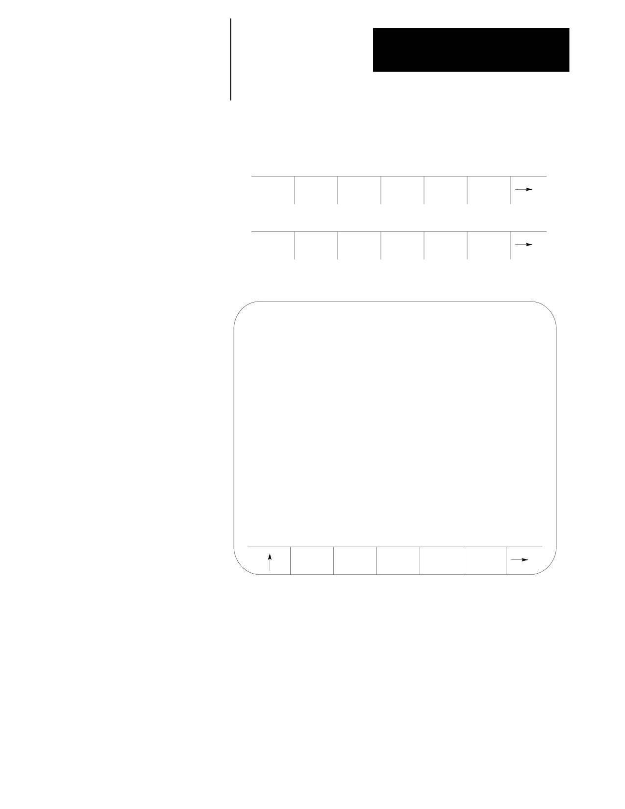
To access the protectable part program directory:
1.
Press the {PRGRAM MANAGE} softkey.
(softkey level 1)
PRGRAM
OFFSET
MACRO
PRGRAM
SYSTEM
MANAGE
PARAM
CHECK
SUPORT
FRONT
ERROR
PASS-
SWITCH
PANEL
MESAGE
WORD
LANG
The control displays the main program directory screen:
SELECTED PROGRAM:
MAIN
DIRECTORY
PAGE
1
OF
1
NAME
SIZE
COMMENT
MAIN
2.3
O12345
14.3
RRR
9.3
THIS IS A TEST PROG
TEST
3.9
4 FILES
120.2
METERS FREE
ACTIVE
EDIT
RESTRT
DISPLY
COPY
PRGRAM
PRGRAM
PRGRAM
PRGRAM
PRGRAM
5-43
Chapter 5
Editing Programs On Line
2.
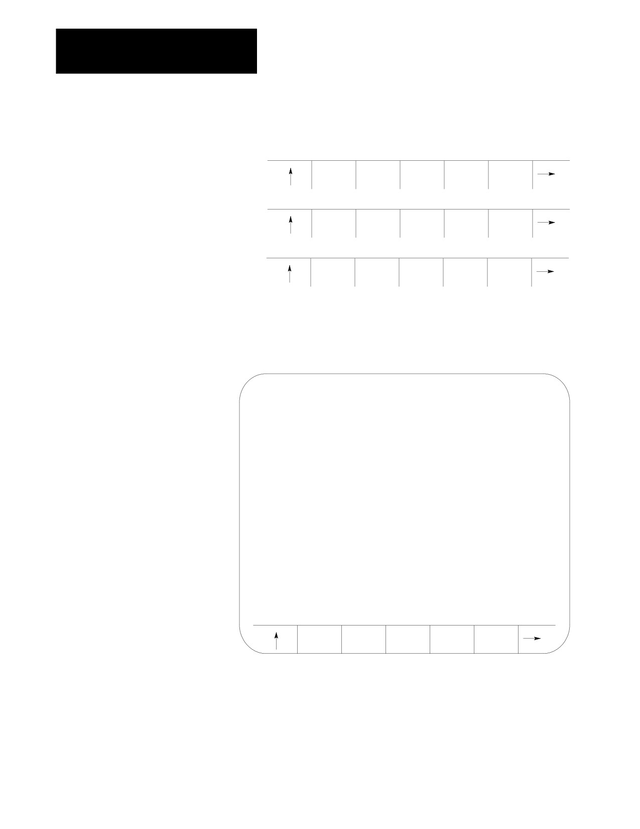
Press the {CHANGE DIR} softkey.
(softkey level 2)
ACTIVE
EDIT
RESTRT
DISPLY
COPY
PRGRAM
PRGRAM
PRGRAM
PRGRAM
PRGRAM
VERIFY
PRGRAM
DELETE
RENAME
INPUT
PRGRAM
COMENT
PRGRAM
PRGRAM
DEVICE
REFORM
CHANGE
MEMORY
DIR
Important: The control does not display the {CHANGE DIR} softkey
if your password does not allow you access to it.
The control displays the protectable directory screen:
SELECTED PROGRAM:
PROTECTABLE DIRECTORY
PAGE
1
OF
1
NAME
SIZE
COMMENT
PROTECT1
2.3
PROTECT2
14.3
PROTECT3
9.3
THIS IS A PROTECTED
PROG
PROTECT4
3.9
4 FILES
120.2
METERS FREE
REFORM
CHANGE
NCRYPT
SET-UP
MEMORY
DIR
MODE
NCRYPT
5-44