9/Series CNC Lathe. Operation and Programming Manual - page 4

Chapter 3
Offset Table and Setup
3.6
Use this feature to change the values set for the single--digit feedrates.
When a single--digit F--word is encountered during block execution, the
Single- digit Feedrate Table
control looks to the single--digit feedrate table for a feedrate. The feedrate
in this table corresponding to the single digit then becomes the active
feedrate. For more details on single--digit feedrate F--words, refer to
chapter 18.
If you are using a dual--processing system, single--digit feedrate values
operate differently. Refer to page 30-5 for details.
Important: Feedrates must always be entered into the single--digit feedrate
table in units of inches per minute (IPM) or millimeters per minute
(MMPM), depending on the current active feedrate mode (G70/71).
To display or alter the values in the single--digit feedrate table, follow these
steps:
1.
Press the {SYSTEM SUPORT} softkey.
2.
Press the {PROGRAM PARAM} softkey.
Figure 3.12
Tool Offset
3.
Press the {F1 - F9} softkey to display the single--digit feedrate table
as shown in Figure 3.12.
Important: Feedrates are displayed in inch or metric depending on which
is the active mode. IPM (inches per minute) or MMPM (millimeters per
minute) is displayed at the top of the screen, indicating the currently active
mode.
4.
Use the up or down cursor keys to move the block cursor to the
feedrate parameter to be changed. The selected feedrate appears in
reverse video.
5.
Change feedrate values in two ways:
Press This Softkey:
Then:
{REPLCE VALUE}
type in the new value. Press [TRANSMIT]. The
value typed in replaces the old value for that
feedrate.
{ADD TO VALUE}
type in the new number. Press [TRANSMIT].
The value typed in is added to the old value for that
feedrate.
3-23
Chapter 3
Offset Tables and Setup
6.
Exit the feedrate parameter screen in two ways:
Press This Softkey:
To:
{UPDATE & EXIT}
to save recent changes made to and leave the
feedrate parameter screen.
{QUIT}
to exit the feedrate parameter screen without
saving changes.
END OF CHAPTER
3-24
Chapter
4
Manual/MDI Operation Modes
4.0
This chapter describes the manual and MDI operating modes. Major topics
include:
Chapter Overview
Topic:
On page:
Mechanical handle feed
4-8
Removing an axis
4-8
Manual machine homing
4-9
MDI mode
4-11
Important: This manual assumes that the rotary or push-button MTB
panel is being used and standard PAL to run that MTB panel has been
installed. For applications that use a custom MTB panel or that do not use
standard PAL to run the MTB panel, refer to documentation prepared by
your system installer.
4.1
To go into the manual mode, select MANUAL under <MODE SELECT>. If
Manual Operating Mode
you are not equipped with a <MODE SELECT> button or switch, press the
{FRONT PANEL} softkey followed by the left/right arrow key to select the
mode.
When you select the manual mode, both the axis position data and the part
program currently active are displayed in the data display area if the
normal display is used for softkey level 1.
Press <CYCLE STOP> to abort manual operations. The system installer has
the option, however, to designate some other switch to abort manual
operations in the PAL program. See documentation provided by your
system installer for details.
4-1
Chapter 4
Manual/MDI Operation Modes
Figure 4.1
Data Display in MANUAL Mode
E-STOP
PROGRAM[ MM
]
F
00000.000 MMPM
X
00000.000
S
0.0
Z
00000.000
T
1
U
00000.000
W
00000.000
MEMORY 30000 MDI STOP
N 99999
(First 4 blocks
of program shown here)
(PAL messages)
PRGRAM
OFFSET
MACRO
PRGRAM
SYSTEM
MANAGE
PARAM
CHECK
SUPORT
4.1.1
In the jog modes, the motion of the cutting tool is controlled by the use of
Jogging an Axis
pushbuttons, switches, or hand pulse generators (HPGs). Typically these
are mounted on or near the MTB panel.
The cutting tool can be jogged by using three different methods:
continuous jog ---- the axes move continuously while a pushbutton on
the MTB panel is held.
incremental jog ---- the axes move a predetermined amount each time a
pushbutton on the MTB panel is pressed.
HPG jog ---- the axes move when an HPG is turned by hand and an axis
has been selected on the MTB panel.
Normally, the axes can only be jogged in manual mode. Your system
installer can write PAL to allow jogging in the automatic and MDI modes.
See page 4-6.
4-2
Chapter 4
Manual/MDI Operation Modes
The control can be equipped with an optional offset jogging feature,
activated by a switch installed by the system installer. When this feature is
active, all jog moves are used to offset the current work coordinate system
and no position registers are changed. See page 4-6 for details.
Only normal single-axis jogs (one axis at a time in the continuous,
incremental, or HPG modes) are permitted during a jog retract operation.
See 7-17.
Important: S--Curve Acc/Dec is not available during manual jogged
motion.
4.1.2
To continuously jog an axis:
Continuous Jog
1.
Select CONTINUOUS under <JOG SELECT>.
2.
Select the feedrate for continuous jog under <SPEED/MULTIPLY>.
3.
Press the <AXIS/DIRECTION> button for the axis and direction to jog.
The axis moves while the button is held down.
If you want to:
Then:
alter the feedrate selected with
select a <FEEDRATE OVERRIDE> %
<SPEED/MULTIPLY>
jog the axis at a special AMP assigned
press and hold the <TRVRS> when jogging
traverse feedrate and ignore the setting
<SPEED/MULTIPLY>
jog moves that use the traverse feedrate
select a <RAPID FEEDRATE
OVERRIDE> %
Important: It is possible to jog more than one axis at a time. To jog
multiple axes, press and hold more than one axis direction button. The
selected axes will drive at the feedrate chosen under <SPEED/MULTIPLY>.
If the selected feedrate is above a specific axis maximum allowable
feedrate, that axis drives at its maximum feedrate. The feedrate for the
other selected axes is not affected.
4.1.3
Incremental jog manually moves an axis a predetermined amount each
Incremental Jog
time an <AXIS/DIRECTION> button is pressed. To use incremental jog:
1.
Select INCREMENTAL under <JOG SELECT> .
2.
Select the jog increment under <SPEED/MULTIPLY>. The jog
increment is equal to an amount specified in AMP for each selection
under <SPEED/MULTIPLY>.
4-3
Chapter 4
Manual/MDI Operation Modes
3.
Press the <AXIS/DIRECTION> button for the axis and direction to jog.
The control makes one incremental move each time the
<AXIS/DIRECTION> button is recognized. Until the control completes
the execution of the incremental move, no other jog moves are
recognized on that axis. This includes attempts to perform other
incremental moves on that axis.
The control will normally jog the axes the selected distance and direction
at the feedrate set in AMP for the MED feedrate. It is possible for the
system installer to select a different feedrate with a specific PAL Program.
Refer to documentation prepared by the system installer for details.
Important: You can jog more than one axis at a time. To jog multiple
axes, press more than one axis direction button. The selected axes drive at
the feedrate chosen under <SPEED/MULTIPLY>. If the selected feedrate is
above a specific axis maximum allowable feedrate, that axis drives at its
maximum feedrate. The feedrate for the other selected axes is not affected.
4.1.4
This section describes the procedure for jogging an axis with a hand pulse
generator (HPG). It is assumed here that the system is configured for only
HPG Jog
one HPG. If the system installer has chosen to install more than one HPG,
they may not function as described here. For details, refer to
documentation provided by the system installer.
To jog an axis with a hand pulse generator (HPG):
1.
Select HANDWHEEL under <JOG SELECT> .
2.
Select the distance that the axis moves for one division of the HPG
with <SPEED/MULTIPLY>. The distance the axis moves per division is
equal to an amount specified in AMP for each selection under
<SPEED/MULTIPLY>.
Important: The x1000 and x10000 selections under
<SPEED/MULTIPLY> are not usable in HPG jog mode.
3.
Press the <AXIS/DIRECTION> button for the axis to jog. The direction
the axis will move is determined by the direction the HPG is rotated
and is unaffected by the <AXIS/DIRECTION> button.
Important: It is possible to jog more than one axis at a time with the HPG
if the system installer has written PAL to allow it. Refer to documentation
prepared by the system installer for details.
4.
Typical HPG configuration will result in:
clockwise ---- plus (+) direction for the axis
counterclockwise ---- minus (-) direction for the axis
4-4

Chapter 4
Manual/MDI Operation Modes
Figure 4.2
HPG Feed
-
+
4.1.5
If desired the system installer can enable a feature that allows control over
Arbitrary Angle Jog
the angle in which a multi-axis jog move will take through the installation
of some optional switches.
When this feature is activated, the operator selects two different axes to
define a plane for the arbitrary angle jog to take place. Then, an angle is
selected (between 0°and 360°) to define a vector for the jog to take place.
This angle is referenced from the first axis chosen to define the current
plane. The system installer has the option to predefine this plane and
vector in PAL. Refer to the documentation prepared by the system installer
on selecting an arbitrary angle jog.
Once this vector has been defined, a jog move can be made along the
defined vector by selecting HPG incremental or continuous jogging modes
in the normal fashion. See page 4-1. The direction that the tool will
travel along the defined vector is determined by your system installer in
PAL or by the operator by the position of another optional switch.
The feedrate of the tool is equal to the current feedrate as determined by
the <SPEED/MULTIPLY> and <FEEDRATE OVERRIDE> . This feedrate is the
vectorial feedrate for the cutting tool. Individual axis feedrates
automatically adjust to produce the designated vectorial feedrate. To jog at
the maximum feedrate as set in AMP, hold the <TRVS> button down while
jogging in continuous mode.
4-5
Chapter 4
Manual/MDI Operation Modes
4.1.6
The control may be equipped with an optional jog offset feature, activated
by a switch installed by the system installer. When this function is active,
Jog Offset
all jog moves made are added as offsets to the current work coordinate
system.
Normally, jogging occurs in the manual mode. The system installer has the
option to enable a “Jog on the Fly” feature that will allow jogging in
automatic or MDI mode for the purpose of jogging an offset. To jog in
automatic or MDI mode both the “Jog on the Fly” and jog offset features
must be active. Normally, the system installer will enable both of these
features with the same switch. Refer to documentation provided by the
system installer for details.
“Jog on the Fly” can be performed at any time
during automatic operation, even while blocks are being executed.
To use this feature, follow these directions:
1.
Turn on the switch to activate the jog offset function. Refer to
documentation provided by the system installer.
2.
Change to manual mode unless the control is equipped for the “Jog
on the Fly” feature which allows jogging in MDI and Automatic
modes. If equipped with “Jog on the Fly,” turn on the switch to
activate it. For details, refer to documentation prepared by the system
installer.
3.
Jog the axis by using any of the available jog types, with the
exception of homing, as described on page 4-8. The control adds
the amount of the jog move as offsets to each jogged axis
immediately when the jog takes place.
Important: When the jog move is made, the axis position displays do not
change on the screen unless the currently active screen is the absolute
screen as described on page 8-6. This is because the value is being added
to the work coordinate system offset and the control does not recognize
any tool motion on the coordinate system.
4.1.7
The control stops tool motion during overtravel conditions. Overtravel
Resetting Overtravels
conditions can occur from 3 causes:
Hardware Overtravel ---- the axes reach a travel limit, usually set by a
limit switch or sensor mounted on the axis. Hardware overtravels are
always active.
Software Overtravel ---- commands cause the cutting tool to pass a
software travel limit. Software overtravels are active only after the axis
has been homed provided the feature has been activated in AMP by the
system installer.
4-6
Chapter 4
Manual/MDI Operation Modes
Programmable Zone Overtravel ---- the axes reach a travel limit
established by independent programmable areas. Programmable Zones
are activated through programming the appropriate G-code.
These 3 causes of overtravel are described in detail in chapter 12.
When an overtravel condition occurs, all axis motion stops, the control is
placed in cycle stop, and one of the following error messages is displayed.
Message:
Description:
HARDWARE OVERTRAVEL (-) BY AXIS (X)
indicates that the specified axis has tripped
either the + or - hardware limit switch mounted
on the machine.
SOFTWARE OVERTRAVEL (+) BY AXIS (X)
indicates that an attempt was made by the
specified axis to enter the overtravel area
defined by the softlimits in either a positive or
negative direction.
VIOLATION OF ZONE (2) BY AXIS (X)
This message indicates that an attempt was
made to enter the overtravel area defined by
programmable zone 2 or 3.
When a software or zone overtravel has taken place, you cannot move the
axis in the same direction as the overtravel. Only axis motion in the
reverse direction is possible.
Reset a hardware overtravel condition depending on the E-Stop circuit
design and the way PAL was programmed by your system installer.
To reset a software or programmable zone overtravel condition:
1.
Determine whether the control is in E-Stop. If it is not, go to step 4.
2.
Look for and eliminate any other possible conditions that may have
caused emergency stop, then make sure that it is safe to reset the
emergency stop condition.
3.
Press the <E-STOP RESET> button to reset the emergency stop
condition. If the E-Stop does not reset, it is a result of some cause
other than overtravel causing E-Stop.
4.
Make sure it is safe to move the axis away from the overtravel limit.
5.
Use any of the jog features described on page 4-1, except homing
and jog offset, to manually move the axis away from the limit. Any
attempt to jog the axis in the direction of the overtravel will not be
allowed.
4-7
Chapter 4
Manual/MDI Operation Modes
4.2
This feature lets you disable the servo drives, and allows the axes to be
moved by external means (such as a hand crank attached to the ball screw)
Mechanical Handle Feed
without requiring the control to be in E-Stop. When this feature is enabled,
(Servo Off)
all position displays get updated as the axes are moved.
Use this feature in conjunction with the digitize feature described in
chapter 5.
This feature only enables when the control is in the Cycle Stop state and
the axes are not being jogged at the time of request. To use this feature, it
must be enabled in PAL by your system installer. Refer to your system
installer’s documentation for details on how the “Mechanical Handle Feed”
feature is activated and used.
4.3
Use this feature to allow the removal of a rotary table or other axis
attachment from a machine without requiring the system to be
Removing an Axis
re-configured. When activated, the control ignores messages that may
(Axis Detach)
occur resulting from the loss of feedback from a removed axis such as
servo errors.
Important: This feature removes the selected axis from the control as an
active axis. Any attempt to move the removed axis results in an error.
This means that part programs that use the removed axis name cannot be
executed. Jog moves and MDI commands that attempt to move the
removed axis also results in an error.
This feature can only be enabled in AMP. The axis must be selected as
“Detached” to be considered removed. Refer to your system installers
documentation for the necessary steps involved in actually physically
removing axis hardware from a specific machine.
4-8
Chapter 4
Manual/MDI Operation Modes
4.4
The machine home return operation means the positioning of a specified
linear or rotary axis to a machine-dependent fixed position, which is called
Manual Machine Homing
the machine home. This position is established via a home limit switch
mounted on the machine and the encoder marker.
The execution of machine home establishes the machine coordinate
system. Since all of the AMP-assigned work coordinate systems and all of
the programmable zones are referenced from the zero point of the machine
coordinate system, none of these features are available until the machine
homing operation has been conducted. Homing the axis should be the first
operation done on the control after power-up.
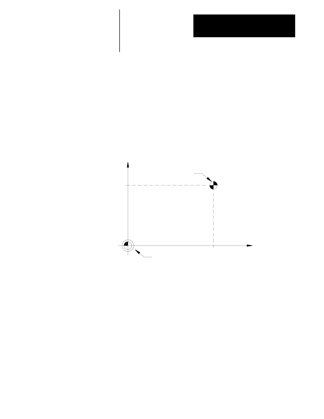
Figure 4.3
Machine Home
+X
Machine
home
point
A
AMP-defined home
coordinates
X=A
Z=B
+Z
Machine coordinate
B
system zero point
The following procedure describes how the control is homed manually by
using the pushbuttons on the MTB panel. Manual homing may be
different for some machines depending on the PAL program written by
your system installer.
Important: When a homing request is made the feedback device for the
axis (typically an encoder) must encounter at least one marker before
tripping the homing limit switch. If the axis is close to the home limit
switch you should jog the axis away from this switch before attempting a
homing operation.
Important: Automatic homing is available. Refer to page 14-12.
4-9
Chapter 4
Manual/MDI Operation Modes
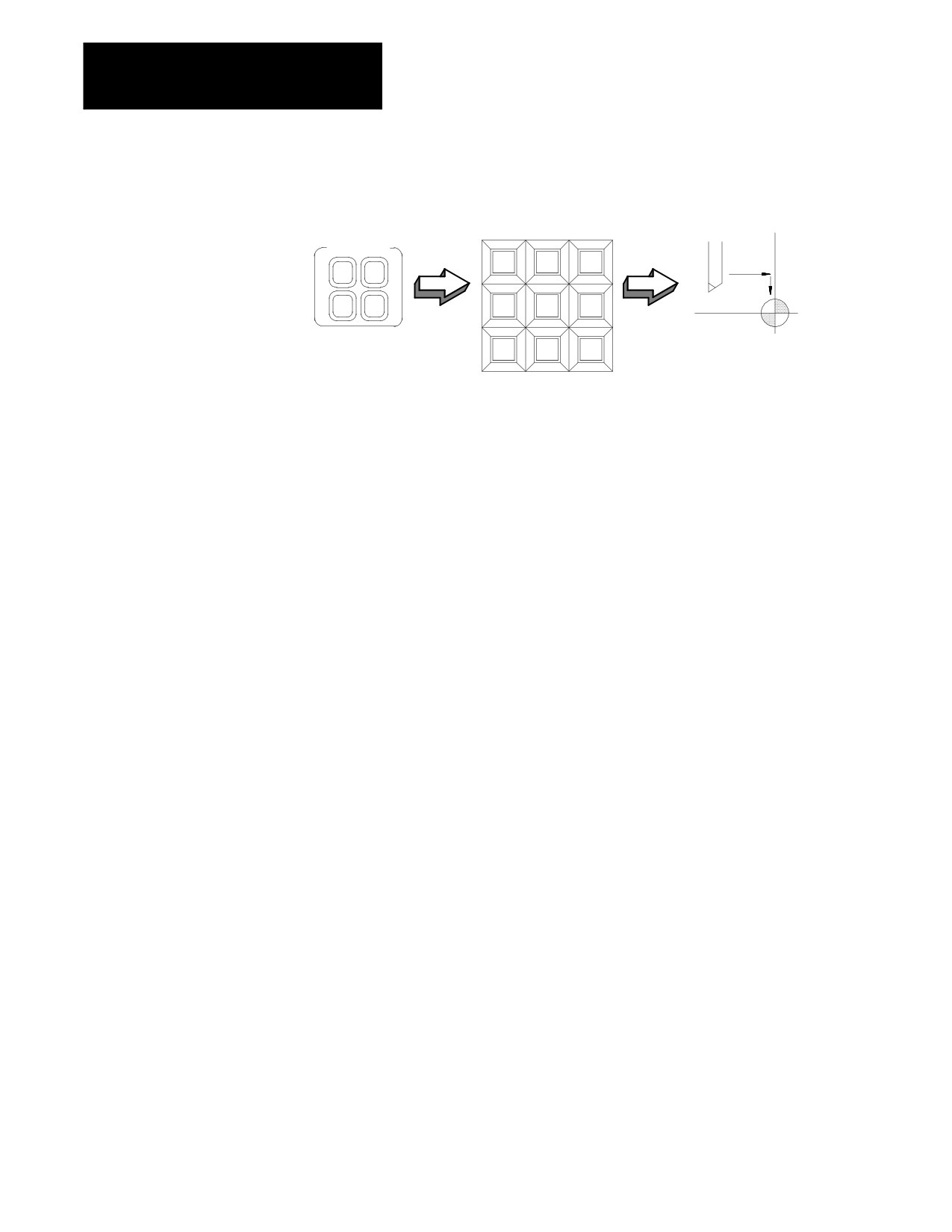
Figure 4.4
Manual Machine Home
AXIS/DIRECTION
Cutting tool
JOG SELECT
+X
+4
--X
INCR
CONT
HAND
HOME
+Y
TRVRS
--Y
Machine home
+Z
--4
--Z
To execute the manual return to machine home position:
1.
Select HOME under <JOG SELECT>.
2.
Place the control in manual mode. See page 4-1.
3.
Determine the direction that each axis must travel to reach the home
limit switch. Refer to your system installer on the location of the
home limit switch on a specific machine.
4.
Press the <AXIS/DIRECTION> button for the axis and direction to
home. You can select more than one axis at one time. The axis
selected moves at the feedrate under <SPEED/MULTIPLY>.
Important: If you choose the wrong direction for an axis, it will continue to
travel in the selected direction until it contacts a hard limit and an overtravel
will occur. See chapter 12. Your system installer has the option to enable
some button or switch (typically Cycle Stop) through the PAL program to
abort a jog operation or prevent the user from homing the axis in the wrong
direction. Refer to your system installer’s documentation for details.
The axis homes when :
1.
The axis moves until it trips its home limit switch, then the axis
decelerates to a stop.
2.
The axis then reverses direction and moves off the home limit switch
at a feedrate specified in AMP.
3.
The controller records the distance to the nearest encoder marker or
null position.
4.
The control then moves in a direction specified in AMP, an amount
equal to the home calibration value, specified in AMP, plus the
distance from the encoder marker or null position.
4-10
Chapter 4
Manual/MDI Operation Modes
This locates the machine home position. When the axis reaches this
position, the control resets the position registers to a machine coordinate
value specified in AMP. This establishes the zero point of the machine
coordinate system.
Important: During the machine home operation, softlimits and
programmable zones are not active. All active coordinates offsets are
cancelled.
4.5
In manual data input (MDI) mode, machine operations can be controlled
MDI Mode
by entering program blocks directly by using the keys on the operator
panel.
To begin MDI operations, select MDI under <MODE SELECT> or press the
{FRONT PANEL} softkey followed by the left and right cursor keys to select
the mode if not equipped with a mode select switch.
Important: If desired, your system installer has the option of disabling G-
or M-code AMP-defined paramacro calls in MDI mode. For details on
paramacros, refer to chapter 28.
To insert blocks in an active, executing, program by using MDI, the control
must be in the end of block state to allow the selection of MDI mode. If a
program is interrupted while executing in automatic mode by pressing
cycle stop, the control will not allow the selection of MDI since the control
is in cycle suspended state not end of block state, and a mode change is not
accepted.
CAUTION: When program blocks are executed in MDI, no
tool tip radius compensation (TTRC) is allowed. If TTRC was
previously active before the MDI blocks are executed, it is
temporarily canceled for the execution of the MDI blocks.
Refer to chapter 21 for details on the effect of MDI on TTRC.
Any TTRC G-codes that are programmed in MDI mode affect
the cutter compensation mode (G41, G42, or G40) when
compensation is re-activated.
Important: It is possible to call subprograms or paramacros within an
MDI program, however, there are limitations to the allowable commands.
Refer to chapter 28 on paramacros for details on illegal MDI commands
for these features.
4-11
Chapter 4
Manual/MDI Operation Modes
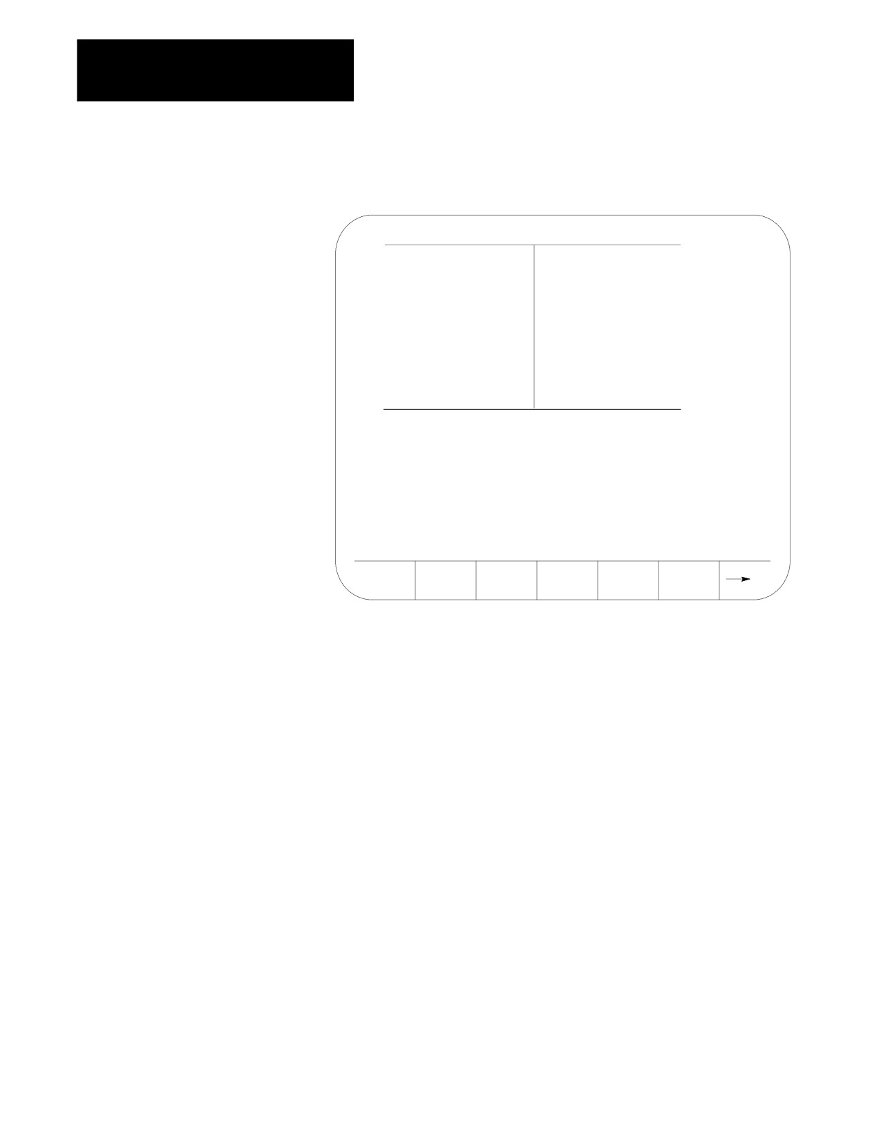
Figure 4.5
Program Display Screen in MDI Mode
E-STOP
PROGRAM[ MM
]
F
00000.000 MMPM
X
00000.000
S
0
Z
00000.000
T
1
U
00000.000
W
00000.000
MEMORY 30000 MDI STOP
N 99999
(First 4 blocks
of MDI shown here)
(PAL messages)
PRGRAM
OFFSET
MACRO
PRGRAM
SYSTEM
MANAGE
PARAM
CHECK
SUPORT
4.5.1
Operating procedures in the MDI mode include:
MDI Basic Operation
1.
When it is in MDI mode, the control accepts standard programming
blocks.
2.
Key in programming blocks (refer chapter 10). Each block, up to a
maximum of 62 characters, is separated with an end of block
statement. The blocks entered appear in the input area of the screen
(lines 2 and 3). The complete MDI program should be entered on
these lines since once you send the blocks to control memory, they
cannot be edited or added to.
The input cursor is the cursor shown on the input lines (lines 2 and 3
on the screen). To move the cursor right and left in the input area,
press and hold the [SHIFT] key while pressing the left and right
cursor keys. A new character will be inserted to the left of the cursor
automatically when you press any character key.
If you make a mistake keying in a character before it is sent, that
character can be edited by using the input cursor described on
page 2-37.
4-12
Chapter 4
Manual/MDI Operation Modes
3.
Pressing the [TRANSMIT] key transmits the blocks to control memory.
Once the blocks have been sent to control memory, you cannot send
any more MDI blocks until all of the previous set has been executed.
The control displays the first 4 blocks of the MDI program entered
on lines 17-20 with an ! (exclamation point) just to the left of the
blocks. If you insert lines by using MDI within a program selected
for automatic execution, the control inserts the MDI blocks just
before the next block to be executed.
If you need to abort the MDI program due to an error in the MDI
program or any other reason, discard the MDI program by executing
a control reset operation.
4.
The MDI blocks can then be executed continuously by pressing the
<CYCLE START> button in either the AUTO or MDI mode. The single
block, block retrace, and jog retract features are also available for
MDI programs (see sections 7.1.4, 7.10, and 7.9 respectively for
details on these features).
The control displays an “@” symbol next to any MDI blocks that
have been executed.
The error message:
“NO MORE MDI BLOCKS”
appears if you press cycle start in the MDI mode when there are no
more MDI blocks remaining in memory to be executed.
If:
Then:
the MDI blocks were entered
the control returns to automatic mode and continues executing
into an executing part program
the part program.
you execute the MDI program in
execution halts when the control encounters the first block of
the MDI mode
the part program.
4-13
Chapter 4
Manual/MDI Operation Modes
Figure 4.6
MDI Mode Program Screen
E-STOP
PROGRAM[ MM
]
F
00000.000 MMPM
Z
00000.000
S
0
R X
00000.000
T
1
C
359.99
MEMORY 30000 MDI STOP
N 99999
(First 4 blocks
of MDI shown here)
(PAL messages)
PRGRAM
OFFSET
MACRO
PRGRAM
SYSTEM
MANAGE
PARAM
CHECK
SUPORT
Important: Performing a block reset operation causes the control to abort
the current MDI program block or skip the following MDI program block.
See page 2-4 for details. By performing a control reset operation as
described, the control erases all MDI blocks that have not been executed in
the MDI program.
END OF CHAPTER
4-14

Chapter
5
Editing Programs On Line
5.0
This chapter describes the basics for editing programs on line (at the
keyboard), including:
Chapter Overview
Topic:
On page:
Selecting the program to edit
5-2
Editing programs
5-4
Programming aids {QUICKVIEW}
5-16
Digitizing a program (Teach)
5-28
Deleting program {DELETE}
5-36
Renaming programs {RENAME}
5-37
Displaying a program {DISPLAY}
5-38
Displaying comments {COMENT}
5-39
Copying programs {COPY PRGRAM}
5-41
You can edit programs off line (at a personal computer). Uploading,
copying, and some file management operations can be performed on a PC.
These offline operations are described in chapter 6.
5-1
Chapter 5
Editing Programs On Line
5.1
This section provides information on how to select a part program for
editing. You can only edit part programs on line that you have stored in
Selecting the Program To
control memory. If a part program is on tape or another storage device and
Edit
you must edit it on line, copy this program to memory as described in
chapter 9.
Important: You can edit programs that are selected as active for
execution. Edit operations being performed on an active program must be
exited before that program can actually be executed in automatic mode.
If an:
is displayed to the left of the part program
name, it means that the program is currently:
A
active
E
open for editing
AE
active and open for editing
To begin an edit operation on an active or inactive part program:
1.
Press the {PRGRAM MANAGE} softkey. The program directory screen
appears (see Figure 5.1).
(softkey level 1)
PRGRAM
OFFSET
MACRO
PRGRAM
SYSTEM
MANAGE
PARAM
CHECK
SUPORT
FRONT
ERROR
PASS-
SWITCH
PANEL
MESAGE
WORD
LANG
5-2
Chapter 5
Editing Programs On Line
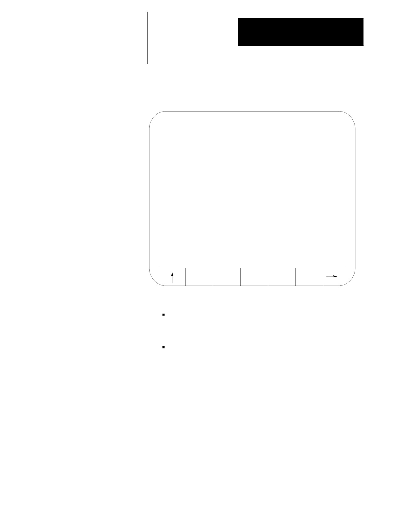
The control displays this main part program directory screen:
Figure 5.1
Part Program Directory
SELECTED PROGRAM:
DIRECTORY
PAGE
1
OF
1
NAME
SIZE
COMMENT
MAIN
2.3
O12345
14.3
RRR
9.3
THIS IS A TEST PROG
TEST
3.9
4 FILES
120.2
METERS FREE
ACTIVE
EDIT
RESTRT
DISPLY
COPY
PRGRAM
PRGRAM
PRGRAM
PRGRAM
PRGRAM
2.
Select the part program you want to edit using two methods:
Key in the program name of the part program to edit or create.
or
Move the cursor to the program name on the program directory
screen using the up or down cursor keys.
Important: If you create a new program that is to be used as a
subprogram, see chapter 10 on program names. Programs used as
subprograms must have the letter O as the first character in the program
name, followed by as many as 5 numeric characters.
5-3
Chapter 5
Editing Programs On Line
3.
Press the {EDIT PRGRAM} softkey.
(softkey level 2)
ACTIVE
EDIT
RESTRT
DISPLY
COPY
PRGRAM
PRGRAM
PRGRAM
PRGRAM
PRGRAM
DELETE
VERIFY
PRGRAM
RENAME
INPUT
PRGRAM
PRGRAM
COMENT
PRGRAM
DEVICE
REFORM
CHANGE
MEMORY
DIR
5.2
This section covers how to edit part programs after a program has already
been selected to edit as described on page 5-2.
Editing Programs at the
Control (On Line)
CAUTION: Any edit operation that you perform on a part
program is permanent. You cannot discard any changes to the
program. Programs are saved in memory at the same time they
are edited.
If you are working with a dual-processes system, you need to follow
different edit operations. Refer to page 30-4 for details.
There are two major sections to the edit screen. They are:
Line
Area
Content
2-3
input lines
where the characters appear when typed in on the keyboard
7-20
program display lines
where the control displays the part program blocks as they
have currently been edited
5-4
Chapter 5
Editing Programs On Line
Figure 5.2
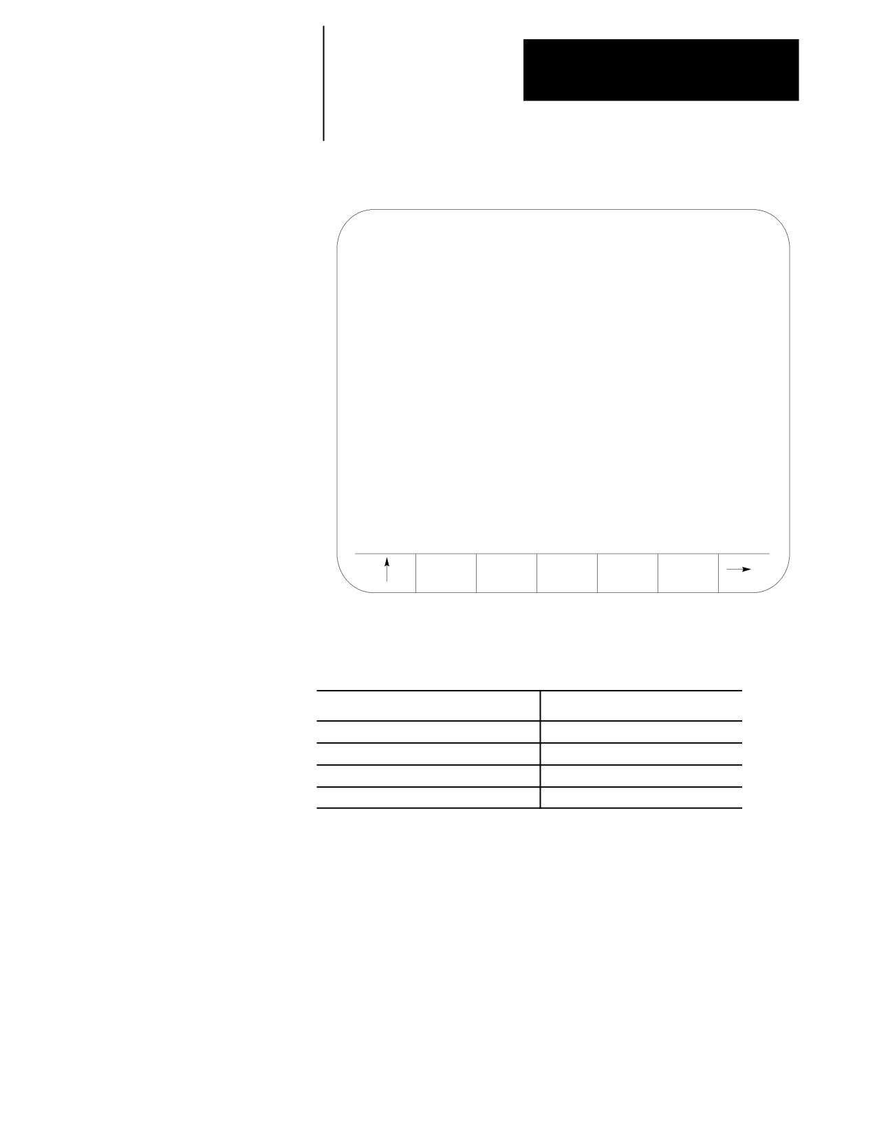
Program Edit Screen
INSERT :
EDIT
FILE : 000001
POS
1*1 MODE : CHAR
N00020
WHILE [#1LT 10] DO 1;
N00025
G01 F1000
X#1;
N00030
G04 P1
N00035
#1 = [#1 + 1];
N00040
END 1;
N00050
M99;
MODIFY
BLOCK
BLOCK
DELETE
EXIT
INSERT
DELETE
TRUNC
CH/WRD
EDITOR
The maximum number of programs that you can have is 328. In order to
store a program, it must use at least 1.3 meters of memory. Use this table to
find out how much part program space there is on your system:
If your system has
this is your part program storage
64K
150 meters
128K
300 meters
192K
450 meters
Extended Part Program Storage (EPPS)
5235 meters
The following subsections describe, in detail, the use of the features
available when editing a part program.
5-5
Chapter 5
Editing Programs On Line
5.2.1
This section describes moving the cursor in the program display area (lines
7-20 of the CRT). It assumes that you have selected a program to edit as
Moving the Cursor
outlined on page 5-2 .
{STRING SEARCH}
Important: The input cursor is the cursor shown on the input lines (lines 2
and 3 on the screen). Refer to page 2-37 for details.
To move the block cursor:
Press these keys on the operator panel:
right and left
right and left cursor keys
up and down
up and down cursor keys
up or down one full screen display
up or down cursor keys while holding down the [SHIFT]
key
To search for a character or character string, press the continue {fi }
softkey to change the softkey functions and follow these steps:
1.
Press the {STRING SEARCH} softkey.
(softkey level 3)
MODIFY
BLOCK
BLOCK
DELETE
EXIT
INSERT
DELETE
TRUNC
CH/WRD
EDITOR
STRING
RENUM
MERGE
QUICK
CHAR/
SEARCH
PRGRAM
PRGRAM
VIEW
WORD
DIGITZ
E
2.
Move the cursor to the beginning or end of the file. Press either the:
To move the cursor to the:
Press:
beginning of the part program
{TOP OF PROG}
end of the part program
{BOT OF PROG}
3.
Key in the character or character string you want to search for, and:
To move the cursor to search:
Press:
forward
{FORWARD}
in reverse
{REVRSE}
If the control cannot find the character or character string, it places
the cursor at the end or beginning of the program being searched,
depending on the direction of the search.
5-6
Chapter 5
Editing Programs On Line
4.
To end the search operation, press the exit [›] softkey.
Sometimes you might want to change the cursor size for editing operations
such as changing, inserting, or erasing. The control has two cursor sizes
available.
Cursor Size:
Description:
single character
is automatically assigned to the cursor when you access
the edit screen.
word
encompasses a word and its value for using erasing,
inserting, or changing operations.
Modify the cursor size in the following manner:
1.
Press the continue {fi } softkey to change the softkey functions.
2.
Press the {CHAR/WORD} softkey to select the block length for the
cursor (character or word). Each time you press {CHAR/WORD}, the
block size changes.
(softkey level 3)
MODIFY
BLOCK
BLOCK
DELETE
EXIT
INSERT
DELETE
TRUNC
CH/WRD
EDITOR
STRING
RENUM
MERGE
QUICK
CHAR/
SEARCH
PRGRAM
PRGRAM
VIEW
WORD
DIGITZ
E
5.2.2
After selecting a part program to be edited, use the following method to
add lines, blocks, or characters to the part program. The control should be
Entering Characters and
in the edit mode at this point with EDIT: displayed in the input area of the
Blocks
screen (lines 2-3 ).
To enter blocks in a program:
1.
Use the up, down, left and right cursor keys to move the block cursor
to the location where you want the program blocks or characters to be
added.
5-7

Chapter 5
Editing Programs On Line
2.
Type the program characters to be entered in the input area. Press the
[EOB] key (end of block) at the end of each block.
If you make a mistake keying in a character before it is sent from the
input area, you can edit the input lines as described on page 2-37.
3.
Press the [TRANSMIT] key to send data from the input lines to the
program display area.
Important: After data has been sent to the program display area of the
screen (lines 7-22), you can no longer edit using the input cursor.
4.
Repeat these steps until the entire program has been entered.
5.2.3
Changing
Changing and Inserting
You can replace characters or words with one or several characters or
{MODIFY INSERT}
words by using the change feature. Follow these steps to change data that
has already been entered into the program display area.
1.
From the edit menu, press the {MODIFY INSERT} softkey until the
MODIFY: prompt is displayed on the input line. The control toggles
between change and insert each time you press {MODIFY INSERT}.
(softkey level 3)
MODIFY
BLOCK
BLOCK
DELETE
EXIT
INSERT
DELETE
TRUNC
CH/WRD
EDITOR
STRING
RENUM
MERGE
QUICK
CHAR/
SEARCH
PRGRAM
PRGRAM
VIEW
WORD
DIGITZ
E
2.
Locate the block cursor in the program display area at the character(s)
that you want to be change by pressing the up, down, left, and right
cursor keys. Characters appear in reverse video on the screen will be
the characters changed.
3.
Key in a new character or word to replace data located by the cursor
in the input area, then press the [TRANSMIT] key.
Important: Only the data that is within the cursor will be changed. If
more data is typed in than is contained in the cursor, the extra data will be
inserted to the right of the cursor. If less data is typed in than is contained
in the cursor, remaining data in the cursor will be deleted.
5-8

Chapter 5
Editing Programs On Line
Example 5.1
Changing Characters
To change Z93 to W93 in the following block:
Program Block
Enter
Notes
(Program Display Area)
(Input Area)
G01X93Z93;
Move the block cursor to the Z in the program display area and toggle
the {MODIFY/INSERT} softkey to “MODIFY:”.
G01X93Z93;
W
Type this data into the input area, then press the [TRANSMIT] key.
G01X93W93;
This is the block of altered commands shown in the program display
area.
Example 5.2
Changing Characters and Inserting At The Same Time
To change X97 to X96.5 in the following block:
Program Block
Enter
Notes
(Program Display Area)
(Input Area)
G01X97Z93;
Move the block cursor to the character 7 in the program display area
and toggle the {MODIFY/INSERT} softkey to “MODIFY:”.
G01X97Z93;
6.5
Type this data into the input area, then press the [TRANSMIT] key
G01X96.5Z93;
This is the block of altered commands shown in the program display
area.
Example 5.3
Changing Words
To change X97 to X42 in the following block first select the word cursor
size (see page 5-7):
Program Block
Enter
Notes
(Program Display Area)
(Input Area)
G01X97Z93;
Move the block cursor to the word X97 in the program display area
and toggle the {MODIFY/INSERT} softkey to “MODIFY:”.
G01X97Z93;
X42
Type this data into the input area, then press the the [TRANSMIT]
key
G01X42Z93;
This is the block of altered commands shown in the program display
area.
5-9
Chapter 5
Editing Programs On Line
Inserting
You can insert characters, words, and blocks to the left of the program
display cursor within an already existing or newly created part program.
Follow these steps to use the insert function.
1.
From the edit menu, press the {MODIFY INSERT} softkey until the
INSERT: prompt is displayed on the input line. The control toggles
between change and insert each time you press the softkey.
(softkey level 3)
MODIFY
BLOCK
BLOCK
DELETE
EXIT
INSERT
DELETE
TRUNC
CH/WRD
EDITOR
STRING
RENUM
MERGE
QUICK
CHAR/
SEARCH
PRGRAM
PRGRAM
VIEW
WORD
DIGITZ
E
2.
Move the cursor in the program display area to the position that is
just right of the location to insert the new data by pressing the cursor
keys.
3.
Key in the characters, words, or blocks of commands to be inserted
into the input area, then press the [TRANSMIT] key.
Example 5.4
Inserting Characters
To change G01X97Z93 to two separate blocks:
Program Block
Enter
Notes
(Program Display Area)
(Input Area)
G01X97Z93;
Move the block cursor to the Z in the program display area and
toggle the {MODIFY/INSERT} softkey to “INSERT:”.
G01X97Z93;
;
Type an EOB character into the input area,then press the
[TRANSMIT] key.
G01X97;
Result
Z93;
5-10

Chapter 5
Editing Programs On Line
Example 5.5
Inserting Characters
To change “X123.0” to “X123.034” when the following is displayed on the
input line:
Program Block
Enter
Notes
(Program Display Area)
(Input Area)
N1000X123.0Z45.0;
Move the cursor to “Z”and toggle the {MODIFY/INSERT}
softkey to “INSERT:”.
N1000X123.0Z45.0;
34
Type this data into the input area, then press the
[TRANSMIT] key.
N1000X123.034Z45.0;
Result
Example 5.6
Inserting Words
To change X93.Z20.; to X93.W31.Z20.;
Program Block
Enter
Notes
(Program Display Area)
(Input Area)
X93.Z20.;
Move the cursor to the Z and toggle the
{MODIFY/INSERT} softkey to “INSERT:”.
X93.Z20.;
W31.
Type this into the input area, then press the [TRANSMIT]
key.
X93.W31.Z20.;
Result
5.2.4
The control can erase part program data in 3 ways:
Erasing Characters and
Erase a character or a word
Blocks
Erase all the characters from the current location of the cursor to the
EOB code (;)
Erase an entire block
Erasing a Character or Word
1.
First choose whether to erase a character or a word by pressing the
{CHAR/WORD} softkey.
2.
From the edit menu, move the cursor until the character or word you
want to erased is in reverse video.
5-11
Chapter 5
Editing Programs On Line
3.
Press the {DELETE CH/WRD} softkey.
(softkey level 3)
MODIFY
BLOCK
BLOCK
DELETE
EXIT
INSERT
DELETE
TRUNC
CH/WRD
EDITOR
STRING
RENUM
MERGE
QUICK
CHAR/
SEARCH
PRGRAM
PRGRAM
VIEW
WORD
DIGITZ
E
Erasing Commands to the EOB
1.
Move the cursor from the edit menu until the first character or word
to be erased is in reverse video.
2.
Press the {BLOCK TRUNC} softkey. The control block erases all the
information from the cursor to the End of Block character. You
cannot erase the End of Block character using the {BLOCK TRUNC}
softkey.
(softkey level 3)
MODIFY
BLOCK
BLOCK
DELETE
EXIT
INSERT
DELETE
TRUNC
CH/WRD
EDITOR
STRING
RENUM
MERGE
QUICK
CHAR/
SEARCH
PRGRAM
PRGRAM
VIEW
WORD
DIGITZ
E
Example 5.7
Erasing To The End Of Block Character
To erase Z20. from the block below:
Program Block
Enter
Notes
(Program Display Area)
(Input Area)
X93Z20;
Move the cursor to the Z
X93Z20;
Press the {BLOCK TRUNC} softkey.
X93;
Result
5-12

Chapter 5
Editing Programs On Line
Erasing An Entire Block
1.
Move the cursor from the edit menu until it is located on any
character in the block that you want to delete.
2.
Press the {BLOCK DELETE} softkey. This erases the selected block,
including the end of block character.
(softkey level 3)
MODIFY
BLOCK
BLOCK
DELETE
EXIT
INSERT
DELETE
TRUNC
CH/WRD
EDITOR
STRING
RENUM
MERGE
QUICK
CHAR/
SEARCH
PRGRAM
PRGRAM
VIEW
WORD
DIGITZ
E
Example 5.8
Erasing An Entire Block
Program Block
Enter
Notes
(Program Display Area)
(Input Area)
X93M01Z10;
Position the cursor any where in the block
X93M01Z10;
Press the {BLOCK DELETE} softkey.
Result -- -- the block will be completely deleted
Important: If the block consists of more than one line on the CRT the
entire block is deleted, not just the line that contains the cursor.
Erasing a character still in the input area
You can erase characters in the input area (lines 1-2 on the screen) before
you send them to the program display area. Delete the character to the left
of the cursor on the input line by pressing the [DEL] key. A new character
will be inserted to the left of the cursor automatically when you press any
character key. You can move the cursor on the input line by holding down
the [SHIFT] key and pressing the left or right cursor keys.
5-13
Chapter 5
Editing Programs On Line
5.2.5
You can assign each block in a part program up to a five-digit numeric
value following an N address. Refer to these numbers as sequence
Sequence Numbers
numbers. They distinguish one block from another.
{RENUM PRGRAM}
You can assign sequence numbers at random to specific blocks or to all
blocks. Blocks assigned sequence numbers can be called later by
designating their sequence number.
Sequence numbers can be renumbered or assigned in 3 ways:
manually type in a sequence number following an N-word for each
block individually
assign new sequence numbers only to blocks that already have sequence
numbers
assign new sequence numbers to all blocks
Follow these steps to assign or renumber sequence numbers:
1.
From the edit menu, press the continue softkey {fi } to change the
softkey functions.
2.
Press the {RENUM PRGRAM} softkey
(softkey level 3)
MODIFY
BLOCK
BLOCK
DELETE
EXIT
INSERT
DELETE
TRUNC
CH/WRD
EDITOR
STRING
RENUM
MERGE
QUICK
CHAR/
SEARCH
PRGRAM
PRGRAM
VIEW
WORD
DIGITZ
E
3.
Key in an initial sequence number (the number for the first sequence
number), a comma, and an incremental value for the control to add to
each new sequence number. The format to this command is
RENUM: initial-sequence-number, incremental-value
For example
RENUM:5,10
Would make the first sequence number 5, the next 15, 25, 35
Important: You must enter both the initial sequence number and the
incremental value as integer values. If a decimal point is used the control
will issue the error message “ILLEGAL VALUE.”
If no initial sequence number or no incremental-value is given or
both are not entered, the control uses default values of one.
5-14