9/Series CNC Lathe. Operation and Programming Manual - page 2
Chapter 2
Basic Control Operation
Softkey level 1 is the initial softkey level the control displays at power-up.
Softkey level 1 always remains the same and all other levels are referenced
from softkey level 1.
The softkeys on opposite ends of the softkey row have a specific use that
remains standard throughout the different softkey levels.
On the:
Is the:
left
exit softkey displayed with the up arrow {›}
right
continue softkey displayed with the right arrow {fi }
Use the exit softkey {›} on the far left to regress softkey levels. For
example, if you are currently on softkey level 3 and you press the exit
softkey, the softkeys change to the softkeys previously displayed on
softkey level 2. When you press the exit softkey while holding down
the shift key, the softkey display is returned to softkey level 1 regardless
of the current softkey level.
When more than 5 softkey functions are available on the same level, the
control activates the continue {fi } softkey at the far right of the softkey
area. When you press the continue softkey, the softkey functions
change to the next set of softkeys on that level.
Important: The continue softkey is not active when the number of softkey
functions on that level does not exceed 5.
For example:
(softkey level 1)
PRGRAM
OFFSET
MACRO
PRGRAM
SYSTEM
MANAGE
PARAM
CHECK
SUPORT
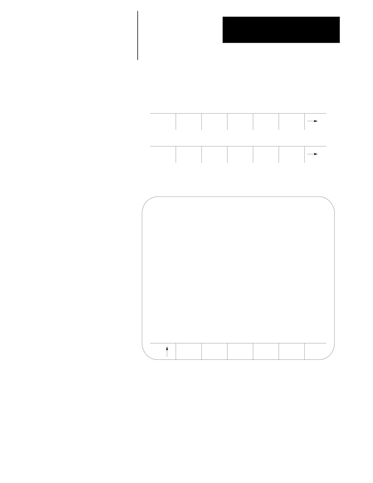
When softkey level 1 is reached, the above set of softkeys is displayed.
Pressing the continue softkey {fi } displays the remaining softkey
functions on softkey level 1.
(softkey level 1)
FRONT
ERROR
PASS-
SWITCH
PANEL
MESAGE
WORD
LANG
The exit softkey is not displayed since the softkeys are already on softkey
level 1.
The softkey functions for level 1 and level 2 are explained in appendix A.
Softkey functions for level 3, or higher, are explained in the sections that
apply to their specific operations.
2-9

Chapter 2
Basic Control Operation
To use a softkey function, press the plain, unmarked button directly below
the description of the softkey function.
Important: Some of the softkey functions are purchased as optional
features. This manual assumes that all available optional features have
been purchased for the machine. If an option is not purchased, the softkey
is blank.
2.1.4
The control can be purchased with a 9-inch monochrome monitor or a
CRT
12-inch color monitor.. Both have identical displays and graphics
capabilities.
Certain lines of the screen are dedicated to displaying specific information:
Lines:
Display information:
line 1
If an error occurs or a message is generated for any reason during
machine/
machine operation or program execution, the control displays the
system message area
corresponding machine/system message in this area. Only the
highest priority, most current message is displayed here.
lines 2-3
When you enter data using the keyboard, the control displays the
input lines
characters corresponding to the keys pressed until you press the
[TRANSMIT] key. Some screens can only have line 2 as an input
line.
lines 4-20
The control displays axis position data, listing of the part program, tool
data display area
offset data, G-, M-, H-, T-, F-, S-, and D-codes, graphics, and other
data, as determined by the selected display. See chapter 8.
lines 21-22
The control displays any messages generated by the control’s PAL
PAL message area
program in this area
lines 23-25
The control displays the currently available softkey functions in this
softkey display area
area.
2.2
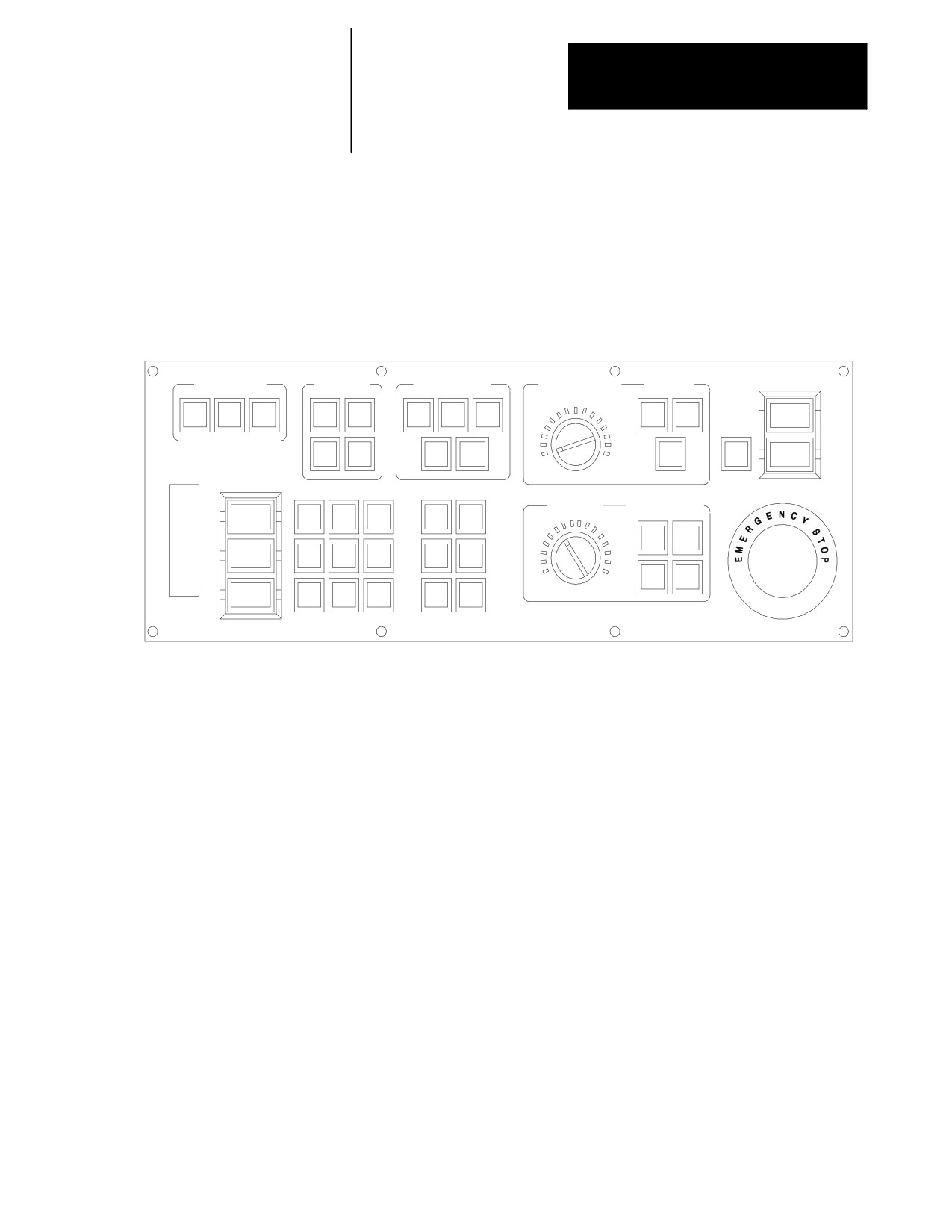
Figure 2.4 shows the push-button MTB panel. Table 2.D explains the
The MTB Panel
functions of the buttons on the MTB panel. Optional or custom MTB
panels may be used. Refer to the documentation prepared by your system
installer for details.
We show switches and button names that are found on the rotary and
push--button MTB panel between the < > symbols throughout this manual.
The push-button MTB panel uses defaults when you turn on power to the
control. Table 2.D contains these defaults.
Most of the buttons on the MTB panel are configured by your system
installer’s PAL program. We assume that PAL has been written as
intended for normal operation. If a switch does not work the way it is
described in this manual, refer to documentation prepared by your system
installer.
2-10
Chapter 2
Basic Control Operation
If you are using a dual-operating system, your MTB panel may operate
differently than described here. Refer to page 30-11 for information about
your MTB panel.
Figure 2.4
Push-Button MTB Panel
SPINDLE SPEED
MODE SELECT
JOG SELECT
SPEED/MULTIPLY
SPINDLE
OVERRIDE
AUTO
MDI
MAN
INCR
CONT
LOW
MEDL
MED
ON
X1
X10
X100
CCW
CW
MEDH
HIGH
ESTOP
HAND
HOME
X1000
X10000
OFF
RESET
OFF
50
120
AXIS
FUNCTION
FEEDRATE
RAPID FEEDRATE
OVERRIDE
OVERRIDE
CYCLE
START
+X
+4
--X
F1
F2
50
100
F1
25
SINGLEBLOCK
+Y
TRVRS
--Y
F3
F4
50
100
0
150
STOP
CYCLE
+Z
--4
--Z
F5
F6
%
19930
2-11
Chapter 2
Basic Control Operation
Table 2.D
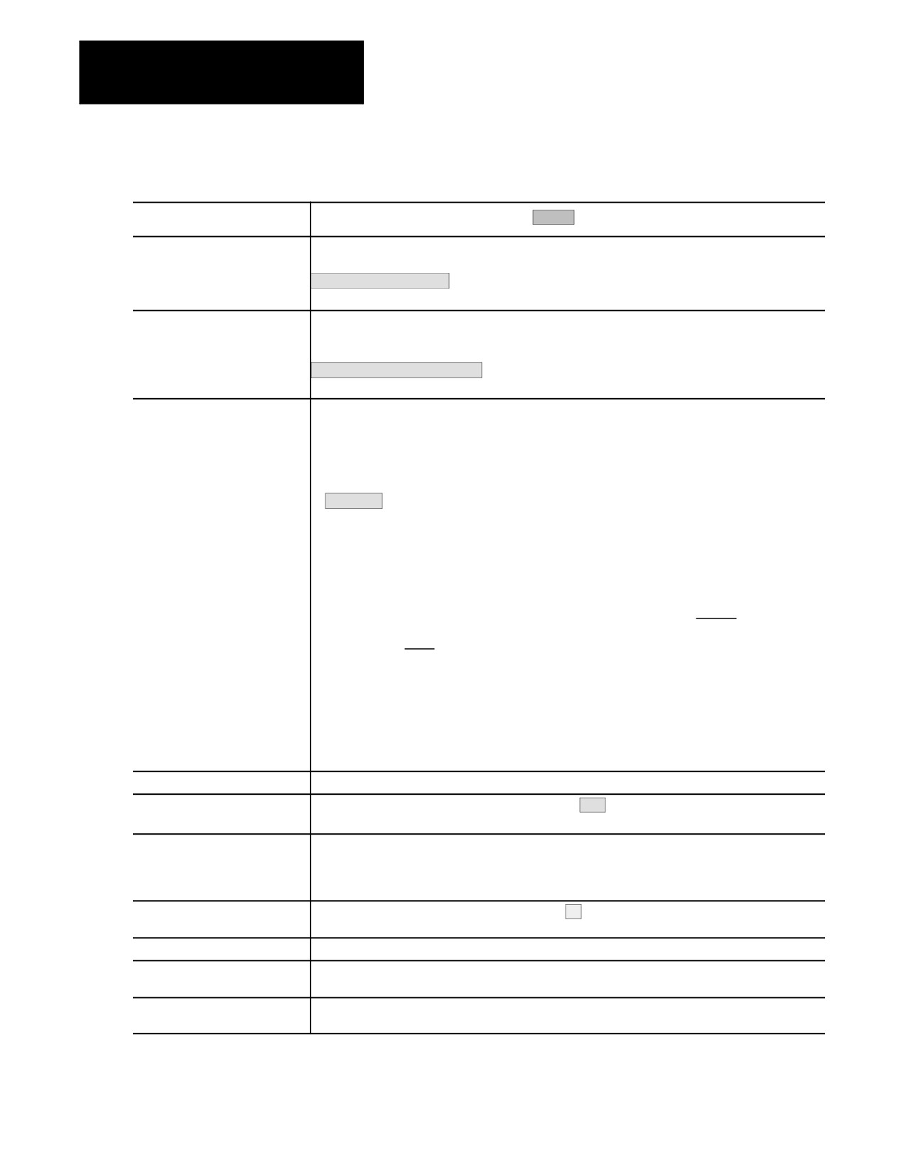
Functions of the Buttons on the Push-Button MTB Panel
Switch or Button Name
How It Works
= Default for Push-Button MTB Panel
MODE SELECT
Selects the operation mode
AUTO -- -- automatic mode
MANUAL -- -- manual mode
MDI -- -- manual data input mode
JOG SELECT
Selects the jog method to be active in manual mode
HANDWHEEL -- -- HPG (hand pulse generator) jog
INCREMENTAL -- -- incremental jog
CONTINUOUS -- -- continuous jog
HOME -- -- machine home
SPEED/MULTIPLY
Selects an axis feedrate or axis feed amount multiplication ratio used in the manual mode. Each
selection modifies the active feedrate by a value set in AMP. Modification also depends on the setting
of <JOG SELECT> as described below:
· HANDWHEEL
When in handwheel jog mode, SPEED/MULTIPLY alters the handwheel resolution by a factor
determined in AMP. Your system installer sets the value for:
- LOW X1
- MEDL X10
- MEDL X100
You cannot use the values listed below for handwheel jog:
- MEDH X1000
- HIGH X10000
· INCREMENTAL
When in incremental jog mode, SPEED/MULTIPLY alters the incremental jog distance by a factor set
in AMP by your system installer. Your system installer sets a value for the selections. The
incremental jog speed is fixed to medium but can still be controlled by
<FEEDRATE OVERRIDE>.
· CONTINUOUS
When in continuous jog mode, SPEED/MULTIPLY acts as a feedrate selection switch which has
values set in AMP by your system installer. Your system installer sets a value for all 5 selections
independently for each axis. <FEEDRATE OVERRIDE> can be used for speed adjustments.
Important: The values for the different <SPEED/MULTIPLY> selections are configured by
your system installer.
SPINDLE SPEED OVERRIDE
Selects the override for programmed spindle speeds in 5% increments within a range of 50% to 120%.
SPINDLE or
Selects spindle rotation, clockwise (CW), spindle stop (
counterclockwise (CCW). Can be
SPINDLE DIRECTION
overridden by any programmed spindle direction command.
FEEDRATE OVERRIDE
Selects a feedrate override percentage for the feedrate programmed with an F word in any of the
feedrates modes (G93/G94/G95) and the reciprocation feedrate programmed with an E word.
<FEEDRATE OVERRIDE> has a range of 0% to 150% of the programmed feedrate and alters the
programmed feedrate in 10% increments. When set to 0%, the control is effectively in feedhold.
RAPID FEEDRATE OVERRIDE
Selects the override for rapid feedrates. Select from
F1, 25%, 50%, and 100% where F1 is a rapid
feedrate override setting established in AMP by the system installer.
EMERGENCY STOP
This button stops machine operation and disables the spindle and axis drives when pressed.
E-STOP RESET
This button resets an emergency stop condition when pressed. Before pressing this button the
condition that caused the E-Stop should be resolved.
CYCLE START
The control begins or resumes part program execution, MDI program execution, or program check
when this button is pressed.
2-12
Chapter 2
Basic Control Operation
Table 2.D (continued)
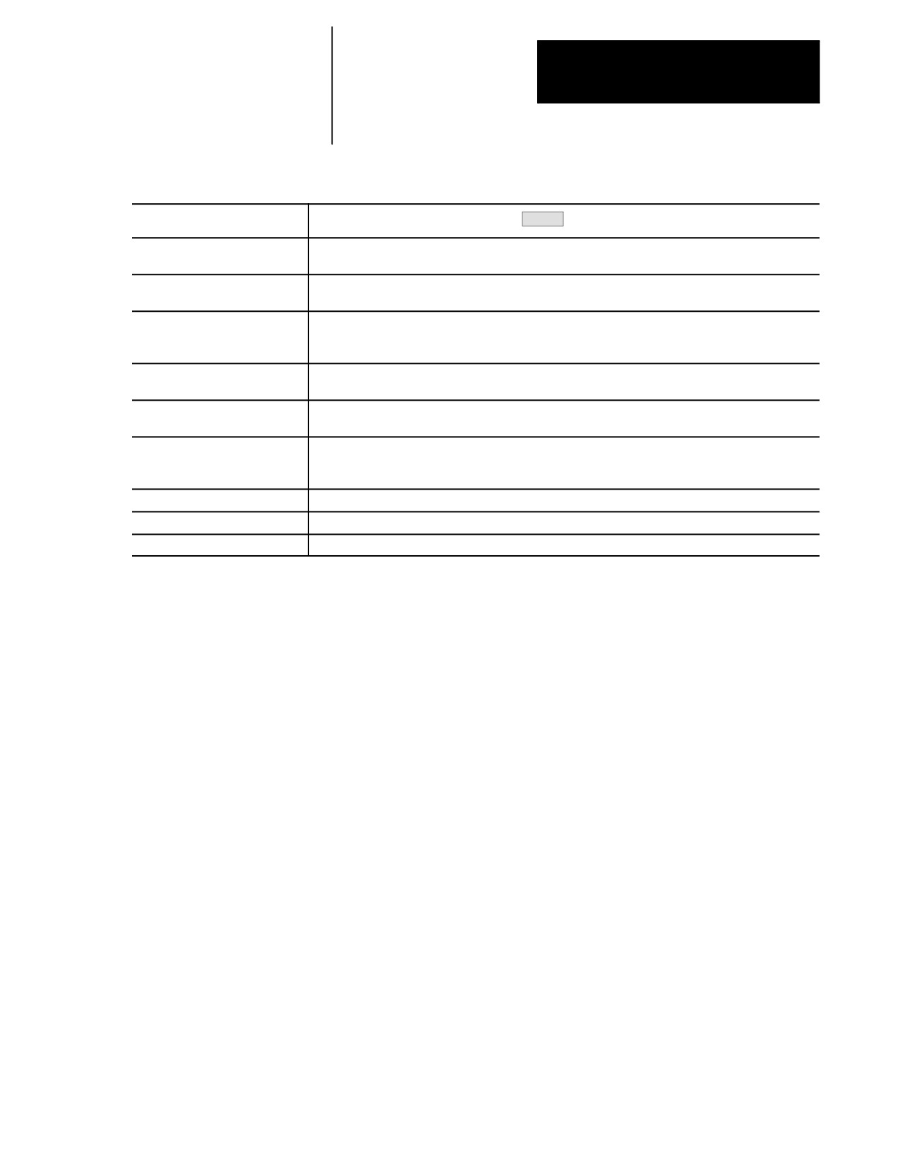
Functions of the Buttons on the Push-Button MTB Panel
Switch or Button Name
How It Works
= Default for Push-Button MTB Panel
CYCLE STOP
The control stops part program execution, MDI execution, or program check when this button is
pressed. If pressed during the execution of a program block a cycle suspend state occurs.
SINGLE BLOCK
The control executes or checks one block of a part program or MDI entry each time the
<CYCLE START> button is pressed when single block is active.
AXIS/DIRECTION
These buttons are used for manual operations. They select an axis and direction when
<JOG SELECT> is set for continuous, incremental, or home. If <JOG SELECT> is set for
handwheel, these buttons select an axis only. Direction is then determined by handwheel rotation.
TRVRS
Hold this button down while executing a continuous jog move to override the active feedrate and jog an
axis in rapid traverse.
F1 - F4
The functions for these buttons are assigned by the system installer. Refer to the documentation
prepared by the system installer for details.
JOG RETRACT
Use jog retract to jog a cutting tool away from the workpiece during automatic or MDI program
execution. The control can retrace the jog moves and return the cutting tool automatically to the
workpiece by pressing <CYCLE START>. Refer to page 7-28 for more on this.
BLOCK RETRACE
To retrace the tool path in a part program already executed (up to 15 blocks), press this button.
ON
Turns on power to the control.
OFF
Turns off power to the control.
Important: Many of the override switch settings may be disabled by
programming the correct M-code or setting a particular paramacro
parameter. Refer to their respective sections for details on these features.
2.3
The 9/Series control offers a software MTB panel that performs many of
Software MTB Panel
the functions of an MTB panel. This feature uses softkeys instead of the
normal switches and buttons of a panel. If the control uses a push-button
{FRONT PANEL}
MTB panel (described on page 2-10), or some other custom panel, the
requests for operations from the panel takes priority. This means that
requests of the software MTB panel are ignored if another request is sent
from a push-button MTB panel or a custom MTB panel.
The software MTB panel’s operation depends on PAL, especially if the
control uses a push-button MTB panel or a custom MTB panel. Refer to
documentation prepared by your system installer for details on using the
software MTB panel. Your system installer uses PAL to disable the
{FRONT PANEL} softkey.
Important: By using the PAL flags $SWF1 and $SWF2, you can enable
and disable features available on the software front panel. Refer to your
PAL reference manual for additional information.
2-13

Chapter 2
Basic Control Operation
The software MTB panel can control these features:
Feature
Description
Mode Select
Select either Automatic, MDI, or Manual modes as the current operating mode of the control.
Rapid Traverse
This feature replaces the feedrate when executing a continuous jog move with the rapid feedrate.
Feedrate Override
Selects a feedrate override percentage for feedrates programmed with an F-word, in 10% increments within a
range of 0% to 150%. When set to 0%, the control is effectively in feedhold.
Rapid Feedrate Override
Selects the override for rapid feedrates. Select from F1, 25%, 50%, and 100%, where F1 is a rapid feedrate
override setting established in AMP by the system installer.
Spindle Direction
Selects spindle rotation, clockwise (CW), spindle stop (OFF), or counterclockwise (CCW). Is overridden by
any programmed spindle direction command.
Spindle Speed Override
Selects the override for programmed spindle speeds in 5% increments within a range of 50% to 120%.
Dry Run Mode
Places the control in Dry Run Mode. This replaces feedrates with the Dry Run feedrates. See page 7-21.
Block Delete
Allows the activation of the block delete feature “/ or /1”(see page 7-1 ). Block delete 2 -- 9 are not available
with the {FRONT PANEL}.
M-Function Lock
Allows select M-, S-, T-, and B-codes to be ignored. See page 7-2.
Optional Stop
This enables or disables the M01 optional stop code. When this feature is “ON,”an M01 in a part program
stops automatic execution. When this feature is “OFF,”an M01 in a part program is ignored. See page 10-30
for details on M01.
Single Block
The control executes or checks one block of a part program or MDI entry each time the <CYCLE START>
button is pressed when this feature is on.
Mirror Image
Mirrors the axis commands in the part program around the selected axis. See page 14-19.
Axis Inhibit
Prevents axis commands from being executed. The control simulates axis motion on inhibited axes by using
Acc/Dec and feedrates; however, no actual axis motion for the inhibited axes is generated. See page 7-20.
Jog the Axes
Allows manual motions to be performed in any one of the jogging modes. See section 4.1. Multi-axis jogs
may not be performed by using the Software MTB feature.
Set Zero
Change the tool’s current position in the work coordinate system to 0 for the selected axis. This is done by
shifting the work coordinate system. See page 11-18.
Block Retrace
This allows up to 15 part program blocks to be retraced during program execution and allow the tool to
automatically re-execute these blocks. See page 7-31.
Jog Retract
Allow the tool to be manually jogged away from the part and then automatically return the tool to the part by
retracing the jogged moves. Up to 15 jog moves can be remembered. See page 7-28.
Cycle Start
The control begins or resumes part program execution, MDI program execution, or program check when you
press this button.
Cycle Stop
The control stops part program execution, or program check when you press this button. If pressed during the
execution of a program block, a cycle suspend state occurs.
2-14
Chapter 2
Basic Control Operation
Software MTB Panel Screen
To use the software MTB panel feature, follow these steps:
1.
From the main menu screen, press the {FRONT PANEL} softkey.
(softkey level 1)
PRGRAM
OFFSET
MACRO
PRGRAM
SYSTEM
MANAGE
PARAM
CHECK
SUPORT
FRONT
ERROR
PASS-
SWITCH
PANEL
MESAGE
WORD
LANG
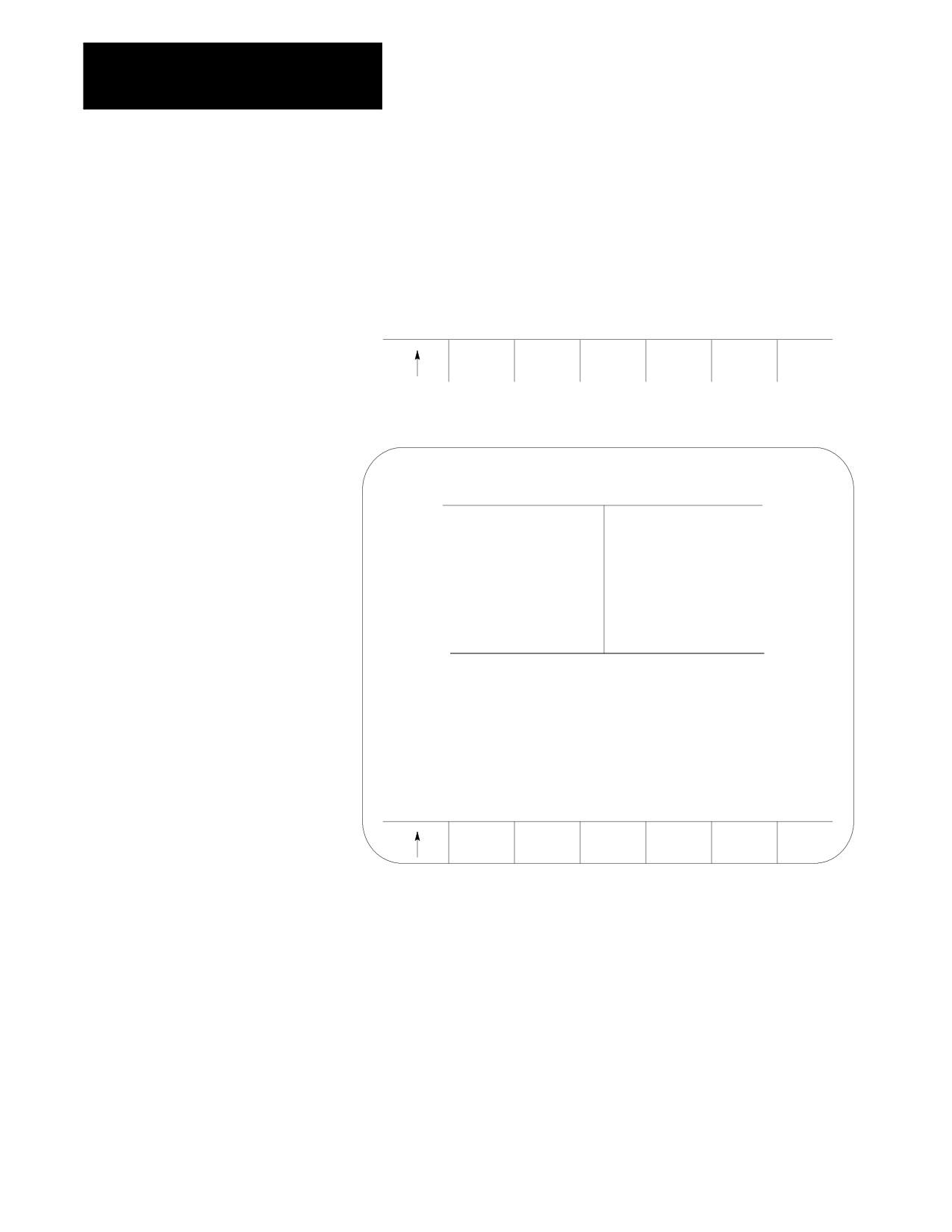
The Software MTB Panel screen displays the current status of the
alterable features.
SOFTWARE FRONT PANEL
MODE SELECT:
MDI
RAPID TRAVERSE:
OFF
FEEDRATE OVR:
0%
RAPID FEEDRATE OVR:
100%
SPINDLE DIRECTION:
CW
SPINDLE SPEED OVR:
50%
DRY RUN MODE:
OFF
BLOCK DELETE:
OFF
M-FUNC LOCK:
OFF
OPTIONAL STOP:
OFF
SINGLE BLOCK:
OFF
MIRROR IMAGE:
AXIS INHIBIT:
USE CURSOR FOR SELECTION
JOG
PRGRAM
AXIS
EXEC
2.
Press the up or down cursor keys to select the function you want to
change. The selected function appears in reverse video.
3.
Alter the value of the function by pressing the left or right cursor keys
(except for the Mirror Image and Axis Inhibit features). When you
select the Mirror Image or Axis Inhibit features, the softkey names
change to the axis names. Press the softkey that corresponds to the
axis (or axes) that you want to assign to these features.
2-15
Chapter 2
Basic Control Operation
Jog Screen
We assumes that you have performed the steps to display the Software
Front Panel screen. Make sure that the function selected on the Software
Front Panel screen is not the Mirror Image or the Axis Inhibit features.
1.
Press the {JOG AXIS} softkey.
(softkey level 2)
JOG
PRGRAM
AXIS
EXEC
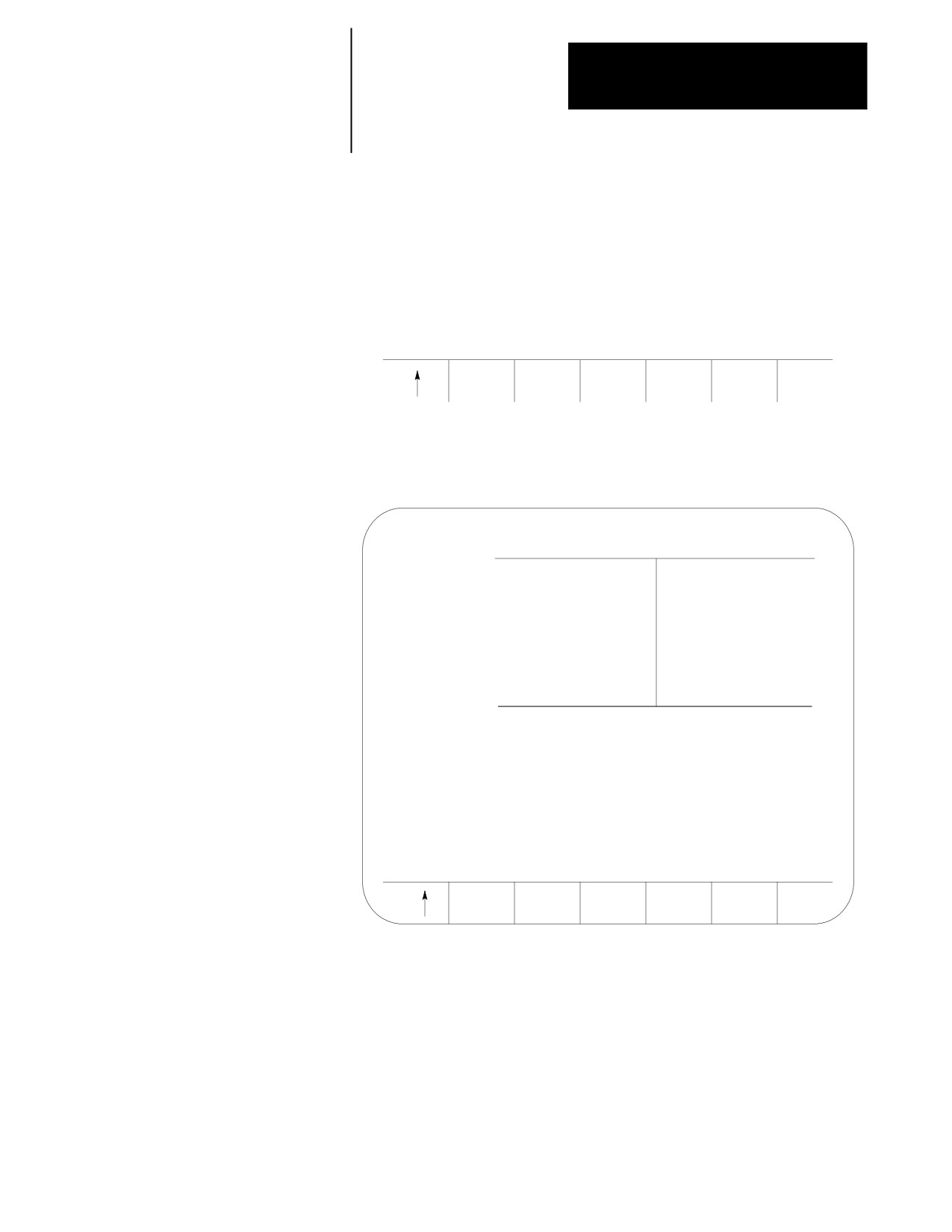
This screen appears:
E-STOP
PROGRAM [mm]
F
0.000 MMPM
Z
0.000
S
0.0
R X
0.000
T 0
C
359.99
FILENAME
SUB NAME
MEMORY
MAN STOP
AXIS SELECT:
X
JOG SELECT:
CONTINUOUS
SPEED/MULTIPLY
LOW
HPG NUMBER
0
SET
JOG
JOG
ZERO
AXIS +
AXIS -
2.
Select the axis, jog type, speed multiply value (see chapter 4), and
HPG number (if HPG has been selected as the type of jog) by using
the up and down cursor keys, and the left and right cursor keys to
alter the value assigned to that function.
3.
If the jog type is not HPG, then press the softkey that corresponds to
the direction on the selected axis to jog (if HPG is the jog type then
the direction of HPG rotation determines the direction to jog).
4.
If you want to shift the current work coordinate system to force the
current tool position to be the zero point of the work coordinate
system, press the {SET ZERO} softkey. The {SET ZERO} softkey does
not function when the control is in handwheel mode.
2-16
Chapter 2
Basic Control Operation
Program Execute Screen
The following assumes that the steps have been performed to display the
Software Front Panel screen (see page 2-15). Make sure that the function
selected on the Software Front Panel screen is not the Mirror Image nor
the Axis Inhibit feature.
1.
Press the {PRGRAM EXEC} softkey.
(softkey level 2)
JOG
PRGRAM
AXIS
EXEC
This screen appears. Before you press this softkey, a program should
have already been selected for automatic execution as described on
page 7-6.
E-STOP
PROGRAM[ MM
]
F
0.000 MMPM
Z
0.000
S
0.0
R X
0.000
T 0
C
359.99
FILENAME
SUB NAME
MEMORY
MAN
STOP
M100;
G90;
Z10;
G70;
BLOCK
JOG
CYCLE
CYCLE
RETRCE
RETRCT
START
STOP
2-17
Chapter 2
Basic Control Operation
2.
Select one of these softkey options:
block retrace
jog retract
cycle start
cycle stop
To Perform a:
Press:
Cycle Start
the softkey that corresponds to the desired feature. Details on these
features are described in chapter 7.
Cycle Stop
the softkey that corresponds to the desired feature. Details on these
features are described in chapter 7.
Block Retrace
the {BLOCK RETRCE} softkey. The control automatically
retraces the previously executed block each time you press. The tool
returns to the start point of Block Retrace when you press the
{CYCLE START} softkey. Details on Block Retrace can be found
in chapter 7.
Jog Retract
the {JOG RETRCT} softkey. This calls up the jog retract screen.
Select: the axis, the type of jog, the speed multiply value (see
chapter 4), or the HPG number (if HPG has been selected as the
type of jog). Use the up and down cursor keys to select the function,
and the left and right cursor keys to alter the value assigned to that
function.
3.
Press the {JOG AXES +} or {JOG AXES -} softkeys to select the
direction to jog the axis. Press the exit {›} softkey when you
complete the jog retract. The cutting tool automatically retraces the
jog moves you made when you pressed the {CYCLE START}. See
chapter 7.
(softkey level 4)
SET
JOG
JOG
ZERO
AXES +
AXES-
2-18
Chapter 2
Basic Control Operation
Figure 2.5
Jog Retract Software MTB Panel Screen
E-STOP
PROGRAM[ MM
]
F
00000.000 MMPM
Z
00000.000
S
0
R X
00000.000
T
12
C
359.99
FILENAME
SUB NAME
MEMORY
MAN STOP
JOG
JOG
AXES+
AXES-
2.4
The basic procedure for turning power on and off is described in this
Power Procedures
section. Refer to the documentation prepared by your system installer for
more specific procedures.
2.4.1
Follow this procedure to turn on power to the control:
Turning Power On
1.
Visually check to make sure that the control and the machine are in
normal operating conditions.
2.
Press the power <ON> button.
Important: Do not touch any other buttons after you press the power <ON>
button until characters appear and remain on the screen.
3.
If characters are not displayed on the screen within 15 seconds, press
the power <OFF> button immediately.
Important: If the screen does not display characters after you press the
power <ON> button within a reasonable warm up period (about 15 seconds),
immediately press the power <OFF> button and contact service personnel.
2-19
Chapter 2
Basic Control Operation
After power has been turned on, the control displays the power turn-on
screen. To activate the main menu, press the [TRANSMIT] key.
You see the main menu screen:
E-STOP
PROGRAM[ MM
]
F
00000.000 MMPM
Z
00000.000
S
R X
00000.000
T
12345
C
359.99
FILENAME
SUB NAME 9999
MEMORY 30000 MDI STOP
(PAL messages)
PRGRAM
OFFSET
MACRO
PRGRAM
SYSTEM
MANAGE
PARAM
CHECK
SUPORT
The softkeys available on the main menu screen are referred to as “level 1”
softkey functions. Some of the softkey functions are purchased as optional
and may not appear exactly as shown.
2.4.2
Follow this procedure to turn off power to the control:
Turning Power OFF
CAUTION: To prevent damage to the machine, never turn off
power while a part program is being executed. Before turning
off power, make sure that the control is in CYCLE STOP.
1.
Before you turn the power off, make sure that the control is in
CYCLE STOP.
2.
Press the <EMERGENCY STOP> button.
3.
Make sure that power is turned off to all peripheral devices (tape
reader, tape punch, etc.) that are connected to the control.
4.
Press the power <OFF> button.
2-20

Chapter 2
Basic Control Operation
2.5
After powering up the control or performing a control reset operation (see
page 2-4), the control assumes a number of initial operating conditions.
Control Conditions at
These are listed below:
Power-Up
Initial Password Access is assigned to the level that was active when
power was turned off (provided that level is a power-up level selected in
access control). If the active level when power is turned off is not a
power-up level, then the control defaults to the next lower level that is a
power-up level. See page 2-23 on access control.
The control is placed in E-Stop. The control is not allowed to come out
of E-Stop if the default AMP is loaded at power-up, or if there is no
PAL program loaded in the system. An appropriate error message is
displayed.
The control defaults to one G-code from each of these groups (as set in
AMP):
Modal Group:
G-code
1
G00
Rapid traverse
G01
Linear interpolation
2
G17
Plane Selected
G18
Plane Selected
G19
Plane Selected
3
G90
Absolute
G91
Incremental
4
G22
Programmable Zone 2 and 3 (On)
G22.1
Programmable Zone 2 (Off) 3 (On)
G23
Programmable Zone 2 and 3 (Off)
G23.1
Programmable Zone 2 (On) 3 (Off)
5
G94
Feed per minute
G95
Feed per revolution
6*
G70
Inch mode
G71
Metric mode
18
G07
Radius Programming Mode
G08
Diameter Programming Mode
* This G code group is only established at power up. A control reset
will not change the last programmed state of this modal G code group.
To show the current operating conditions at any time, access the G-code
status screen as described in chapter 10. If you do this immediately after
power-up, it shows the initial operating conditions selected in AMP along
with other control power-up default conditions.
2-21
Chapter 2
Basic Control Operation
2.6
Press the red <EMERGENCY STOP> button on the MTB panel (or any other
E-stop switches installed on the machine) to stop operations regardless of
Emergency Stop Operations
the condition of the control and the machine.
WARNING: To avoid damage to equipment or hazard to
personnel, the system installer should connect the
<EMERGENCY STOP> button, so that pressing the button opens the
circuit connected to the E-STOP STATUS terminal on the
control. This should disable the axis drives and the spindle
drive circuits, which should both be connected to this terminal.
Refer to the integration manual or the documentation prepared
by your system installer for details.
If equipped with a rotary or push-button MTB panel, the following occurs
automatically after you press the <EMERGENCY STOP> button:
The control displays “E-STOP” in the message area. This indicates that
the control is in the emergency stop state.
The red light in the <CYCLE STOP> button lights up to indicate that the
control is in the feedhold state.
Power to all axis drive motors is turned off.
Important: If you press the <EMERGENCY STOP> button while a part
program is running, program execution can resume at the point of
interruption. Refer to the mid-program start feature described in chapter 7.
2.6.1
Before resetting the emergency stop state, first locate and eliminate the
Emergency Stop Reset
cause of the emergency stop.
If the <EMERGENCY STOP> button is locked in the pressed position, it must
be released before the emergency stop state can be reset. The locked
button can be released in different ways depending on its type. With the
MTB panel, turn the button clockwise until it pops out.
To reset the emergency stop state, press the <E-STOP RESET> button. Once
you push the E--Stop Reset button to clear the E--Stop state, the message,
“RESETTING E--STOP” displays to alert you that the control is attempting
to come out of E--Stop. After the cause of the E--Stop is resolved, the
control clears the “E--STOP” message. If the error condition is not cleared,
the “RESETTING E--STOP” message clears, but the “E--STOP” message
continues to flash as the control remains in E--Stop state.
2-22
Chapter 2
Basic Control Operation
If the E-Stop occurred during program execution, the control may reset the
program when E-Stop reset is performed provided AMP is configured to
do so. Assuming that a control reset is performed, program execution
begins from the first block of the program when <CYCLE START> is
pressed. If the current axis position prohibits this, the operator can
manually jog the axes clear, or consider executing a Mid-Program Start.
See page 7-12. If no control reset is performed, the remainder of the
program block being executed when E-Stop took place is aborted, and a
<CYCLE START> begins program execution at the next block.
Important: If the cause of the E-Stop is not eliminated, the circuit
connected to the E-STOP STATUS terminals remains open, and the
emergency stop state is not reset even when the <E-STOP RESET> button is
pressed.
2.7
Access control lets the system installer assign different functions of the
Access Control
control to different users by means of a password. See section 2.7.2 for a
list of the functions that may be protected on the 9/Series control.
Each protectable function is assigned an access level that is made active
when the operator enters the password. When an access level is made
active, all functions that are assigned to that access level become available.
Access levels range between 1 and 8 where 1 is the highest level and 8 is
the lowest. A different password is assigned to each of the different access
levels. Eight passwords can be assigned.
Access control only applies to the front panel and softkey inputs. It cannot
control inputs from outside the system. For instance, if you control access
to the delete function, the user can’t delete a file, but a file can be deleted
by Mini-DNC software and by Data Highway with the 9/Series Data
Highway Plus Communication Module.
Important: If you do not want to use password protection, simply select
all functions as accessible for access level 8. Since access level 8 is
automatically available at power up, no password is necessary to access
any of the functions of the control. Password protection can also be
disabled by assigning a level at the power-up level by using the
“POWER UP LEVEL” parameter as described in section 2.7.2.
2-23

Chapter 2
Basic Control Operation
2.7.1
This section describes setting or changing the functions assigned to a
particular access level, and changing the password used to activate that
Assigning Access Levels
access level.
and Passwords
Important: Functions or passwords can be assigned to another access
level only if:
If you have a higher access level than the access level you are
attempting to change, this means that if your password is assigned to
access level 6, you can only change the functions or passwords for
access levels 7 and 8. Functions, or a password, cannot be assigned to
access level 6 with a level 6 password.
Functions that are not available to the current user cannot be assigned to
other levels. If a user with access level 6 is changing a lower access
level functions, access level 6 must have access to any functions that are
changed. For example, if you are an access level 6 user, you do not
have access to {SYSTEM SUPORT}, you cannot assign or remove
{SYSTEM SUPORT} to access level 7.
The current user must have access to the {ACCESS CONTROL} function.
To change the functions or password of a lower user number, follow these
steps:
1.
Press the {PASSWORD} softkey.
(softkey level 1)
PRGRAM
OFFSET
MACRO
PRGRAM
SYSTEM
MANAGE
PARAM
CHECK
SUPORT
FRONT
ERROR
PASS-
SWITCH
PANEL
MESAGE
WORD
LANG
2-24

Chapter 2
Basic Control Operation
2.
Press the {ACCESS CONTRL} softkey. If the {ACCESS CONTRL}
softkey does not appear on the screen, the currently active access
level is not allowed to use the {ACCESS CONTRL} function. Enter a
password that has access to {ACCESS CONTRL}.
(softkey level 2)
ACCESS
CONTRL
This screen appears.
PASSWORD NAME -- (current password)
1
ACTIVE PROGRAM
18
ACCESS CONTROL
2
PROGRAM MANAGE
19
SWITCH LANGUAGE
3
EDIT PROGRAM
20
POWER UP LEVEL
4
COPY PROGRAM
21
TIME PARTS
5
RENAME PROGRAM
22
SI/OEM MESSAGE
6
DELETE PROGRAM
23
SCALING
7
DELETE ALL PROGRAM 24
CHANGE DIRECTORY
8
OFFSETS
25
AUX COMM
9
TOOL WEAR
26
SEARCH MONITOR
10
TOOL GEOMETRY
27
11
ACTIVE OFFSET
28
12
BACKUP OFFSET
29
13
QUICK CHECK
30
14
SYSTEM SUPPORT
31
15
PRGRAM PARAMETER
32
16
AMP
33
17
PARAMACRO PROG
34
UPDATE
01
02
03
04
& EXIT
NOTE: Some of these protected features are not available on 9/240 controls.
The softkey names change to display the 8 access levels along with
their corresponding passwords (provided that a password has been
assigned to that access level). Only the password names of access
levels that are lower than the currently active access level are shown.
2-25
Chapter 2
Basic Control Operation
3.
Press the softkey that corresponds to the access level that you want to
change. The pressed softkey appears in reverse video, and the
password name assigned to that access level is moved to the
“PASSWORD NAME.”
Important: If you attempt to change the functions available to an access
level that is equal to or higher than your the current access level, the error
message “ACCESS TO THIS LEVEL IS NOT ALLOWED.” You cannot
change the features that are assigned to your current access level or any
level that is higher than your own.
(softkey level 3)
UPDATE
01
02
03
04
& EXIT
(NAME)
(NAME)
(NAME)
(NAME)
4.
If you want to enter or change the password for the selected level,
edit the password next to the “PASSWORD NAME” prompt by using
the input cursor as described on page 2-37. If you also want to
change the functions for this password, move on to step 5. To save
the change made to the password and leave the access control screen
press the {UPDATE & EXIT} softkey.
Functions that are currently available to the selected level are shown
in reverse video on the access level screen.
5.
Use the up, down, right, and left cursor keys to select the functions to
change for that access level. The selected function is shown with a
flashing > to the left of the function.
6.
Pressing the [TRANSMIT] key toggles the function between accessible
and inaccessible for that access level.
Important: If you attempt to activate or deactivate a function that is not
accessible to the current user’s access level, the message “ACCESS TO
THIS FUNCTION NOT ALLOWED” is displayed. Only features that are
accessible to your the current access level can be selected as accessible or
inaccessible to a lower access level.
7.
Press the {UPDATE & EXIT} softkey to store the changes made to
accessible functions for the user levels and return the control to
softkey level 1.
(softkey level 3)
UPDATE
01
02
03
04
& EXIT
(NAME)
(NAME)
(NAME)
(NAME)
2-26

Chapter 2
Basic Control Operation
2.7.2
The following section describes the functions on the 9/Series control that
can be protected from an operator by the use of a password. If a user has
Password Protectable
access to a function, the parameter associated with that function is shown
Functions
in reverse video on the access control screen.
Access to these functions can be controlled by passwords. Table 2.E
describes the function that is enabled (the operator can perform them) if
the parameter name is shown in reverse video. If the function is not shown
in reverse video, the function is protected and cannot be accessed.
Some parameters enable more than one function. If a parameter that
enables multiple functions is not selected as accessible, some of the
functions that would be enabled by the parameter can be enabled
individually by using other parameters.
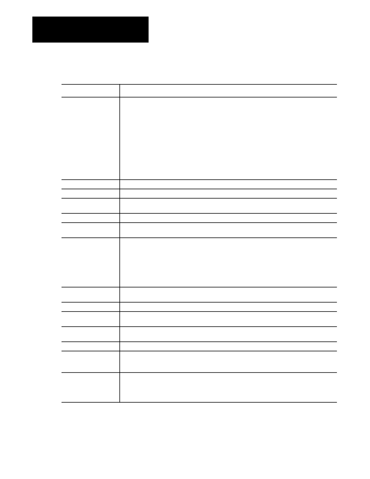
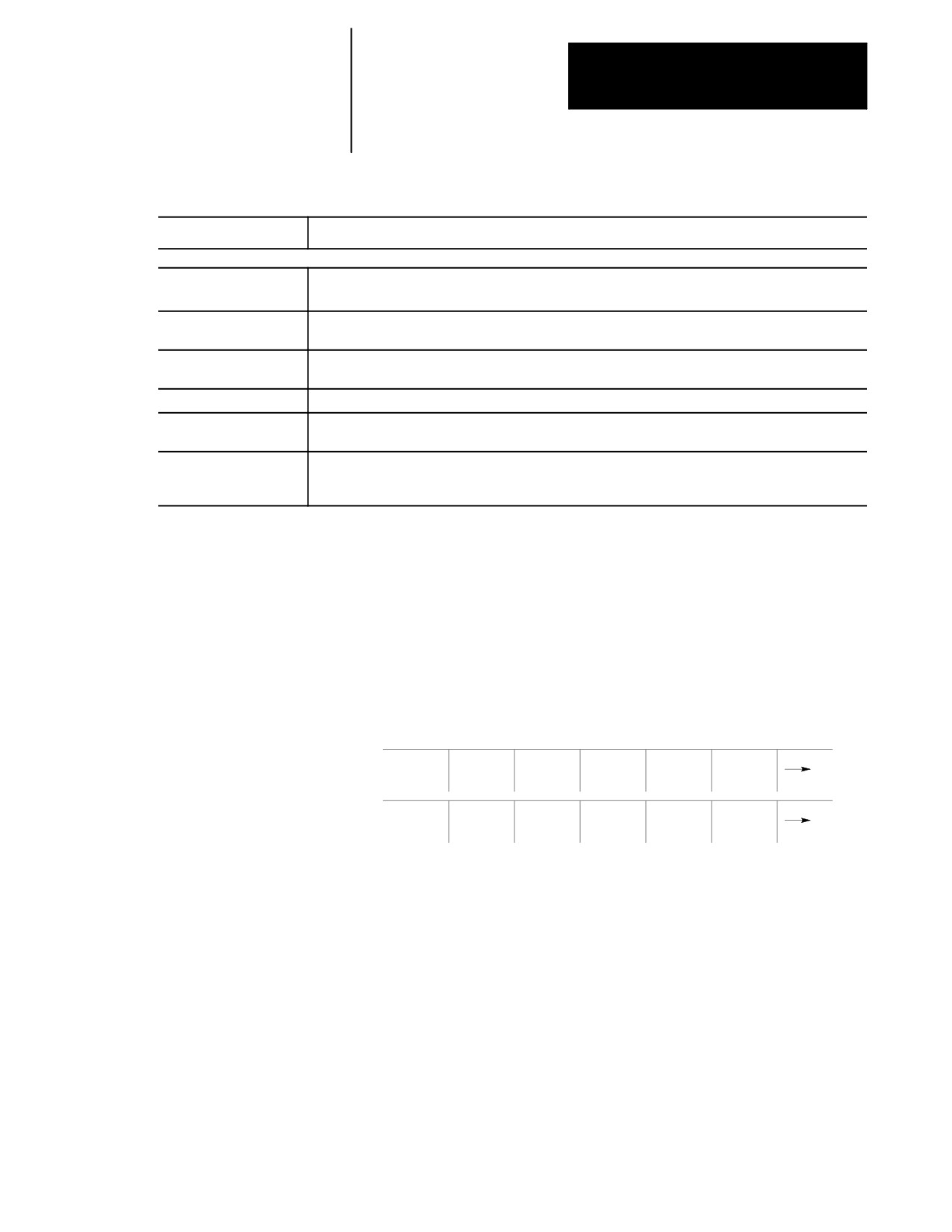
Table 2.E
Password Protectable Functions
Parameter Name:
Function becomes accessible when parameter name is in reverse video:
1) ACTIVE PROGRAM
To access these features, both ACTIVE PROGRAM and PROGRAM MANAGE (number 2 below) must be
assigned to the user.
·
{SELECT PRGRAM} — Select a program for automatic operation.
·
{SEARCH} — Search a part program for a character string or sequence number to begin program
execution at.
·
{MID ST PRGRAM} — Start program execution from some location other than the beginning and
still set all of the parameters previously defined in the program active.
·
{T PATH GRAPH} — Enable the active graphics feature.
·
{CANCEL PRGRAM} — Disable the currently active program from execution.
·
{SEQ STOP} — Choose a sequence number for program automatic program execution to stop at.
2) PROGRAM MANAGE
·
{ACTIVE PRGRAM} — All of the functions in 1 above provided ACTIVE PROGRAM (number 1
above) is also selected.
·
{EDIT PRGRAM} — Edit an existing program or create a new program.
·
{DISPLY PRGRAM} — Display a program using the display function.
·
{COPY PRGRAM} — Copy a program to or from memory.
·
{VERIFY PRGRAM} — Verify that two programs are identical using the verify function.
·
{COMENT} — Add comments to a program name in the directory.
·
{RENAME PRGRAM} — Change a program name.
·
{DELETE PRGRAM} — Delete a single program stored in memory.
·
{REFORM MEMORY} — Delete all programs currently stored in memory.
3) EDIT PROGRAM
{EDIT PRGRAM} — Edit an existing program or create a new program.
4) COPY PROGRAM
{COPY PRGRAM} — Copy a program to or from memory or storage device.
5) RENAME PROGRAM
{RENAME PRGRAM} — Not rename a program name.
6) DELETE PROGRAM
{DELETE PRGRAM} — Delete a single program stored in memory
7) DELETE ALL PROG
{REFORM MEMORY} — Delete all programs currently stored in memory.
2-27
Chapter 2
Basic Control Operation
Table 2.E (continued)
Password Protectable Functions
Parameter Name:
Function becomes accessible when parameter name is in reverse video:
8) OFFSETS
·
{WORK CO-ORD} — Display and alter the preset work coordinate system zero locations and the
fixture offset value.
·
{TOOL WEAR} Display and alter the tool wear amount tables for the different tools.
·
{TOOL GEOMET} — Display and alter the tool geometry tables.
·
{ACTIVE OFFSET} — Change the currently active offset number without requiring the
programming of a different offset number.
·
{TOOL MANAGE} — Alter the tool life indicators and other machine specific tool functions.
·
{RANDOM TOOL} — Allow the use of the random tool tables used to keep track of different tools in
different tool pocket (see chapter 20).
·
{COORD ROTATE} — Rotate all of the work coordinate systems from the machine coordinate
system.
·
{BACKUP OFFSET} — Make a copy of the current tool offset data.
9) TOOL WEAR
{TOOL WEAR} — Display and alter the tool wear amount table for the different tools.
10) TOOL GEOMETRY
{TOOL GEOMET} — Display and alter the tool geometry table.
11) ACTIVE OFFSET
{ACTIVE OFFSET} — Change the currently active offset number without requiring the programming
of a different offset number.
12) BACKUP OFFSET
{BACKUP OFFSET} — Make a copy of the current tool offset data.
13) QUICK CHECK
{QUICK CHECK} — Use the syntax and format checker or the {QUICK CHECK} with graphics
function.
14) SYSTEM SUPORT
·
{PRGRAM PARAM} — Display and change the tables for programmable zones 1 and 2, the
single-digit feedrates, and the fixed-cycle operating parameters.
·
{AMP} — Change any of the online AMP features.
·
{DEVICE SETUP} — Display and change any of the communication parameters for the peripheral
devices.
·
{MONI-TOR} — Display the current I/O configurations and the axis monitor for following error,
distance to marker, etc.
15) PRGRAM
{PRGRAM PARAM} — Display and change the tables for programmable zones 1 and 2, the single-digit
PARAMETERS
feedrates, and the fixed-cycle operating parameters.
16) ONLINE AMP
{AMP} — Display and change the online adjustable machine parameters.
17) PARAMACRO
{MACRO PARAM} — Display or change any of the values in the paramacro tables without using
PARAM
programming commands.
18) ACCESS CONTROL
{ACCESS CONTRL} — Assign different functions to different access levels, change the current
password, or view the functions assigned to the different access levels.
19) SWITCH LANGUAGE
{SWITCH LANG.} — Change the current displays from one language to another.
20) POWER-UP LEVEL
When POWER-UP LEVEL is shown in reverse video, it indicates that if power is turned off when this level
is active, this level automatically becomes active when power is turned back on. If this is not in reverse
video, it indicates that the control defaults to level 8 access control at next power-up.
21) TIME PARTS
·
{SET TIME} — Change or reset time parameters
·
{SET DATE} — Change or reset data parameters
When TIME PARTS is not in reverse video, the operator can only perform the following functions on the
time and parts screen: RUN TIME, CYCLE TIME, and LOT SIZE.
2-28
Chapter 2
Basic Control Operation
Table 2.E (continued)
Password Protectable Functions
Parameter Name:
Function becomes accessible when parameter name is in reverse video:
22) SI/OEM MESSAGE
·
{ENTER MESSAGE} — Enter a new message to be displayed on the control’s power-up screen.
·
{STORE BACKUP} — Store an entered message for the power-up screen to backup memory.
23) SCALING
When SCALING is not in reverse video, the operator still has access to the {SCALNG} softkey; however
values on the screen may not be modified.
24) CHANGE
Allows access to the protectable directory for file edit, direct execution selection, and encrypted output.
DIRECTORY
25) AUX COMM
Allows access to the {AUX COMM} softkey that sets Data Highway Communication Module Parameters.
26) SEARCH MONITOR
Allows access to the {SEARCH MONITOR} softkey that allows searching and monitoring of the
control’s PAL program.
27) PASS THRU ENABLE
Allows access to the {PT ENABLE} softkey that enables remote I/O pass thru of AMP, PAL, and other
ODS features. The {PT ENABLE} softkey is only available when AMP is configured to disallow block
transfers and the system contains remote I/O hardware that has been enabled through PAL.
2.7.3
When you power-up, only functions that are not protectable and functions
that are assigned to access level 8 are available (provided that the active
Entering Passwords
level when power was turned off was not assigned the POWER UP
LEVEL feature). To access the functions that are assigned to a specific
access level, you must enter the password that corresponds to that access
level. To enter a password, follow these steps:
1.
Press the {PASSWORD} softkey.
(softkey level 1)
PRGRAM
OFFSET
MACRO
PRGRAM
SYSTEM
MANAGE
PARAM
CHECK
SUPORT
FRONT
ERROR
PASS-
SWITCH
PANEL
MESAGE
WORD
LANG
2-29
Chapter 2
Basic Control Operation
E-STOP
ENTER PASSWORD:
PROGRAM [INCH]
F
0.000 MMPM
Z
00000.000
S
0
R X
00000.000
T
1
C
359.99
MEMORY
MAN STOP
ACCESS
CONTRL
2.
Enter the password you want to activate by typing it in on the input
line with the keys on the operator panel. The control displays * for
the characters you entered. If you make an error entering the
password, edit the input line as described on page 2-37.
3.
When the password is correct, press the [TRANSMIT] key. The access
level that the password is assigned to is made active, and the control
enables all of the functions that are assigned to that access level.
2.8
The control provides 3 basic operation modes:
Changing Operating Modes
manual (MAN or MANUAL)
manual data input (MDI)
automatic (AUTO)
You can select a mode by using <MODE SELECT> on the MTB panel, or
using the {FRONT PANEL} softkey. This is configurable by your system
installer. Both means of selection cannot be available. Details on using
the {FRONT PANEL} softkey are given on page 2-13.
Depending on the current control status, a mode change request cannot be
honored. Operating modes may not be changed if any of these are true:
The control is in E-Stop.
The control is in the cycle-suspend state. This results when a program
is halted during the execution of a block.
2-30
Chapter 2
Basic Control Operation
The control is executing a threading- or multiple-pass turning cycle.
Important: Your system installer may have written PAL to disable the use
of the {FRONT PANEL} softkey to change modes. If this is the case, then
changing modes can be performed by using only <MODE SELECT> on the
MTB panel.
Manual mode
To operate the machine manually,
select MAN or MANUAL under <MODE SELECT>
or
press the {FRONT PANEL} softkey.
Use the left/right arrow keys to change the mode select options if using
{FRONT PANEL}.
For details on Manual Mode operation, see chapter 4.
Figure 2.6
Manual Mode Screen
E-STOP
PROGRAM[ MM
]
F 00000.000
MMPM
Z
00000.000
S
0
R X
00000.000
T
1
C
359.99
MEMORY MAN STOP
N 99999
(First 4 blocks of
program shown here)
(PAL messages)
PRGRAM
OFFSET
MACRO
PRGRAM
SYSTEM
MANAGE
PARAM
CHECK
SUPORT
2-31
Chapter 2
Basic Control Operation
MDI mode
To operate the machine in MDI mode,
select MDI under <MODE SELECT>
or
press the {FRONT PANEL} softkey
Use left/right arrow keys to change mode select options if using
{FRONT PANEL}.
For details on MDI operation, see page 4-11.
Figure 2.7
MDI Mode Screen
MDI:
E-STOP
PROGRAM[ MM
]
F
0
MMPM
Z
00000.000
S
R X
00000.000
T
1
C
359.99
MEMORY MDI STOP
N 99999
(First 4 blocks
of MDI shown here)
(PAL messages)
PRGRAM
OFFSET
MACRO
PRGRAM
SYSTEM
MANAGE
PARAM
CHECK
SUPORT
2-32
Chapter 2
Basic Control Operation
Automatic mode
To operate the machine automatically,
select AUTO under <MODE SELECT>
or
press the {FRONT PANEL} softkey
Use left/right arrow keys to select mode options if using {FRONT PANEL}.
For details on automatic operation, see chapter 7.
Figure 2.8
Automatic Operation Screen
E-STOP
PROGRAM[ MM
]
F
0 MMPM
Z
00000.000
S
0
R X
00000.000
T
1
C
359.99
MEMORY AUTO STOP
N 99999
(First 4 blocks of
program shown here)
(PAL messages)
PRGRAM
OFFSET
MACRO
PRGRAM
SYSTEM
MANAGE
PARAM
CHECK
SUPORT
2-33

Chapter 2
Basic Control Operation
2.9
The control has two screens dedicated to displaying messages. The
MESSAGE ACTIVE screen displays up to nine of the most current
Displaying System and
system messages and ten of the most current machine (logic generated)
Machine Messages
messages at a time. The MESSAGE LOG screen displays a log of up to
99 system messages and a separate log of up to 99 machine messages that
occurred since the last time memory was cleared. For single process
controls, this log displays up to 11 pages of messages (99 messages total)
and up to six pages per process for dual process systems.
Important: The control automatically displays the highest priority, single,
active message on all screens (other than the message screen) on line 1 of
the CRT. If more than one message occurs with the same priority, the
control displays the most recent message (provided no other message is
active with a higher priority).
Use the MESSAGE ACTIVE screen to display all the messages that are
currently active, or the MESSAGE LOG screen to display a log of the
recorded messages. To access these message screens, follow these steps:
1.
From the main menu press the continue {fi } softkey to change the
softkey functions.
(softkey level 1)
PRGRAM
OFFSET
MACRO
PRGRAM
SYSTEM
MANAGE
PARAM
CHECK
SUPORT
2.
Press the {ERROR MESAGE} softkey to enter the MESSAGE ACTIVE
screen shown in Figure 2.9.
(softkey level 1)
FRONT
ERROR
PASS-
SWITCH
PANEL
MESAGE
WORD
LANG
The control displays the currently active messages in sections
dedicated to:
system messages in the top half of the screen
machine messages (logic generated) in the bottom half of the
screen
2-34
Chapter 2
Basic Control Operation
Figure 2.9
Message Active Display Screen
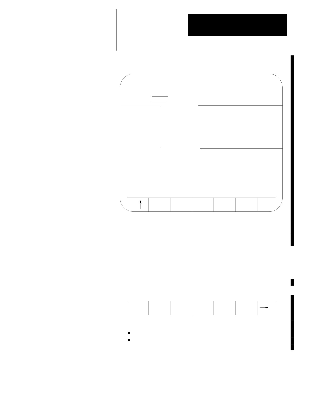
MESSAGE
ACTIVE
SYSTEM MESSAGE
(The system error messages are displayed in this area)
MACHINE MESSAGE
(The logic messages are displayed in this area)
ERROR
CLEAR
LOG
ACTIVE
This is the information displayed on the MESSAGE ACTIVE screen. The
control displays up to 9 active system messages and up to 10 machine
messages. The machine messages represent the currently active logic
messages located on 13 lines through 22 of the 9/Series display screen.
Important: For a listing of system messages and a brief description, refer
to appendix B. For a description of machine messages, refer to the
documentation prepared by your system installer.
3.
Press the {ERROR LOG} softkey to enter the MESSAGE LOG screen
shown in Figure 2.10.
(softkey level 2)
ERROR
CLEAR
LOG
ACTIVE
The control displays the logged messages in sections dedicated to:
system logged messages in the top half of the screen
machine logged messages (logic generated) in the bottom half of
the screen
2-35
Chapter 2
Basic Control Operation
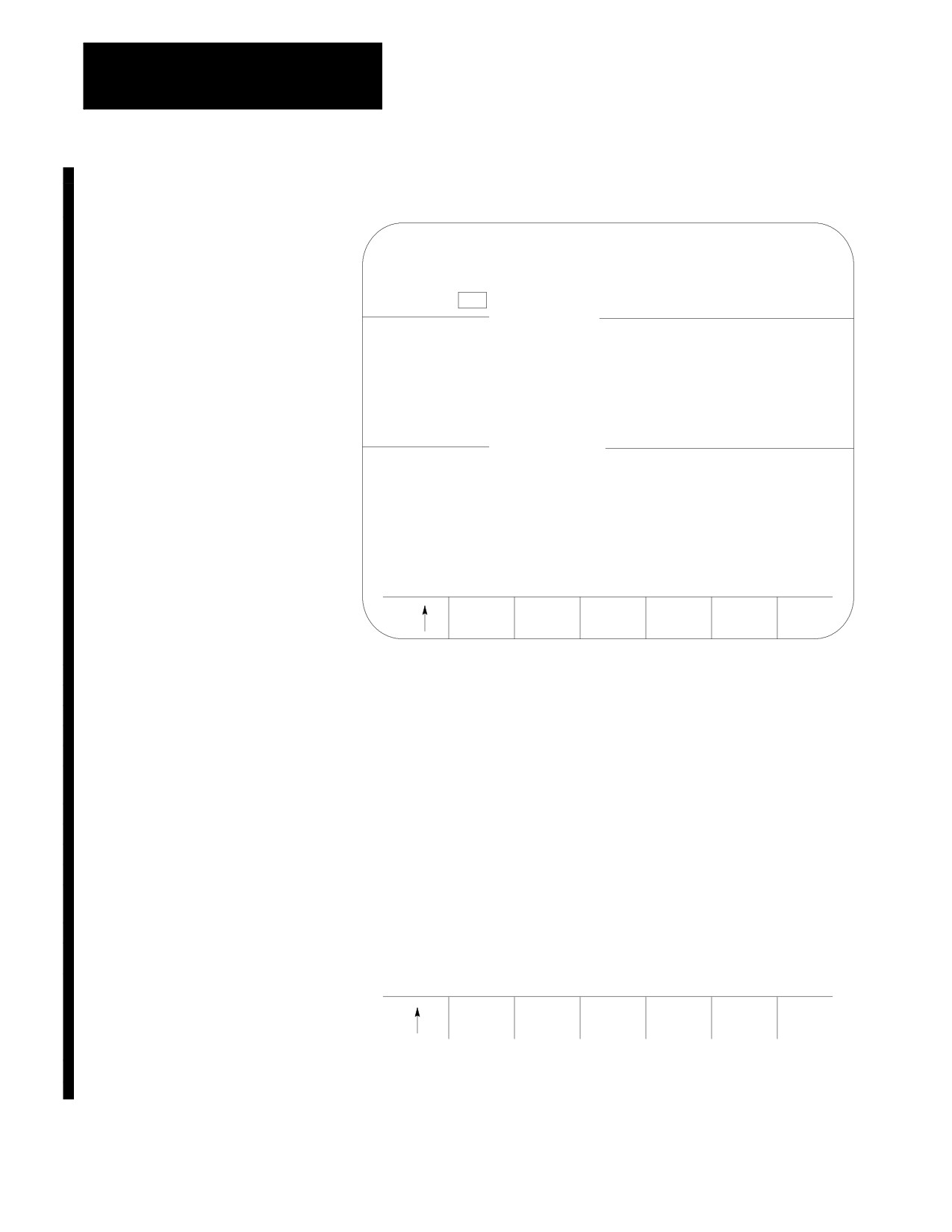
Figure 2.10
Message Log Display Screen
MESSAGE
LOG
PAGE 1 of 9
SYSTEM MESSAGE
(The logged system error messages are displayed in
this area)
MACHINE MESSAGE
(The logged logic messages are displayed in this area)
ACTIVE
TIME
ERRORS
STAMPS
This is the information displayed on the MESSAGE LOG screen. The
control displays up to 99 system messages and up to 99 machine messages.
These are the most recent system messages and machine messages that
occurred on the control since memory was last cleared. To display more
messages, press the [fl ] key while holding the[SHIFT]key. The next page
of the logged messages displays.
Press the {TIME STAMPS} softkey to view the date and time of when
each logged system message and machine message occurred.
Pressing this softkey may cause part of the messages text to be
overlaid by the date and time data. To display the full messages text ,
press the {FULL MESAGE} softkey.
4.
Press the {ACTIVE ERRORS} softkey to return to the
MESSAGE ACTIVE screen.
(softkey level 2)
ACTIVE
TIME
ERRORS
STAMPS
5.
To return to softkey level 1 press the exit {›} softkey while holding
the [SHIFT] key.
2-36
Chapter 2
Basic Control Operation
2.9.1
After the cause of a machine or system message has been resolved, some
messages remain displayed on all screens until you clear them.
Clearing Active Messages
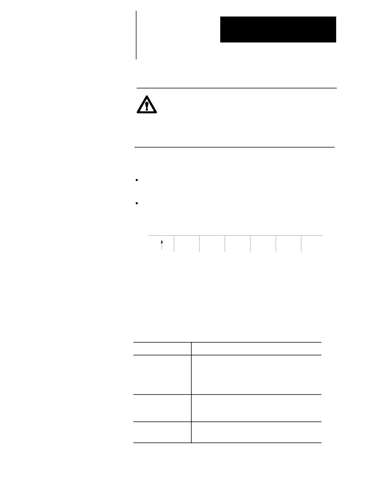
{CLEAR ACTIVE}
CAUTION: Not clearing the old messages from the screen can
prevent messages that are generated later from being displayed.
This occurs when the old resolved message has a higher priority
than the newly generated message. The new message is still
displayed on the message display screen as an active message,
but does not appear in the message area of other screens.
Active messages are cleared from the screen in this way:
Press the [CAN] key to clear the most recent active messages
individually.
Clear all active messages from the error message display screen by
pressing the {CLEAR ACTIVE} softkey.
(softkey level 2)
ERROR
CLEAR
LOG
ACTIVE
Important: Clearing active messages does not correct the problem that
caused the error; it only clears the message from the active file.
2.10
The input cursor is the cursor located on lines 2 and 3 of the screen. It is
The Input Cursor
available when you need to input data by using the operator panel (as
needed in MDI mode, for example). The following section is a description
of how to move the cursor and edit data on the input line by using the keys
on the operator panel.
Cursor Operation:
Description:
Moving the input cursor
To move the cursor right and left in the input area, press and
hold the [SHIFT] key while pressing the left and right cursor
keys. To move the cursor between line 2 and 3 use the left
and right cursor keys while holding the [SHIFT] key. The
up and down cursor keys cannot be used. The input cursor
wraps around when it reaches the end of the screen.
Inserting characters
To insert characters into existing data on the input lines, move
the cursor as described above. Place the cursor just to the
right of the location to insert data. Any data typed in by using
the operator panel is inserted just to the left of the cursor.
Deleting Characters
To delete characters on the input lines move the cursor to the
right of the character to delete. Pressing the [DEL] key
deletes the character to the left of the cursor in the input line.
2-37
Chapter 2
Basic Control Operation
Cursor Operation:
Description:
Deleting all characters on
To delete all entered characters on the input lines press the
the input line
[DEL] key while holding down the [SHIFT] key. All
characters on the input line are deleted.
Sending information
To send information to the control from input line press the
[TRANSMIT] key. All information on the input line is sent to
the control.
2.11
It is sometimes necessary to perform a Reform Memory operation to clear
{REFORM MEMORY}
memory. This is often necessary after one of the following occurs:
the amount of RAM memory that can be used by PAL is changed in
AMP
a new PAL program has been sent to the control (downloading PAL
does not always make it necessary to format)
battery power was lost while the control was turned off (for 9/240)
After 5.5 days, the supercap capacitor, the optional battery, takes over.
This provides at least 6 months of continuous or intermittent backup (for
9/260-9/290)
You must format any time the control displays the error message
“MEMORY CRASH -- REFORMAT.”
This operation can also be performed when you want to delete all part
programs in control memory.
After a format operation is performed, it is not necessary to reinstall AMP
or PAL.
CAUTION: The {REFORM MEMORY} function erases all part
programs that are stored in control memory.
2-38