9/Series CNC Lathe. Operation and Programming Manual - page 1
Allen-Bradley
9/Series CNC
Operation and
Lathe
Programming
Manual
Important User Information
Because of the variety of uses for the products described in this publication,
those responsible for the application and use of this control equipment must
satisfy themselves that all necessary steps have been taken to assure that
each application and use meets all performance and safety requirements,
including any applicable laws, regulations, codes and standards.
The illustrations, charts, sample programs and layout examples shown in
this guide are intended solely for purposes of example. Since there are
many variables and requirements associated with any particular installation,
Allen-Bradley does not assume responsibility or liability (to include
intellectual property liability) for actual use based upon the examples shown
in this publication.
Allen-Bradley publication SGI-1.1, Safety Guidelines for the Application,
Installation, and Maintenance of Solid State Control (available from your
local Allen-Bradley office), describes some important differences between
solid-state equipment and electromechanical devices that should be taken
into consideration when applying products such as those described in this
publication.
Reproduction of the contents of this copyrighted publication, in whole or in
part, without written permission of Allen-Bradley Company, Inc. is prohibited.
Throughout this manual we make notes to alert you to possible injury to
people or damage to equipment under specific circumstances.
WARNING: Tells readers where people may be hurt if
procedures are not followed properly.
CAUTION: Tells readers where machinery may be damaged or
economic loss can occur if procedures are not followed properly.
Warnings and Cautions:
- identify a possible trouble spot
- tell what causes the trouble
- give the result of improper action
- tell the reader how to avoid trouble
Important: We recommend that you frequently back up your application
programs on an appropriate storage medium to avoid possible data loss.
PLC is a registered trademark of Allen-Bradley Company, Inc.
Paramacro and PAL are trademarks of Allen-Bradley Company, Inc.
9/Series Lathe
Operation and Programming Manual
October 2000
Summary of Changes
New Information
The following is a list of the larger changes made to this manual since its
last printing. Other less significant changes were also made throughout.
Error Message Log
Paramacro Parameters
Softkey Tree
Error Messages
Revision Bars
We use revision bars to call your attention to new or revised information.
A revision bar appears as a thick black line on the outside edge of the page
as indicated here.
I Table of Contents
9/Series Lathe
Operation and Programming Manual
Chapter 1
Using This Manual
1.0 Chapter Overview
1-1
1.1 Audience
1-1
1.2 Manual Design
1-1
1.3 Warnings, Cautions, and Important Information
1-3
1.4 Reading this Manual
1-3
1.5 Terms and Conventions
1-4
1.6 Related Publications
1-5
Chapter 2
Basic Control Operation
2.0 Chapter Overview
2-1
2.1 Operator Panel Operations
2-1
2.1.1 Keyboard
2-3
2.1.2 Calculator Function
2-4
2.1.3 Softkeys
2-8
2.1.4 CRT
2-10
2.2 The MTB Panel
2-10
2.3 Software MTB Panel {FRONT PANEL}
2-13
2.4 Power Procedures
2-19
2.4.1 Turning Power On
2-19
2.4.2 Turning Power OFF
2-20
2.5 Control Conditions at Power-Up
2-21
2.6 Emergency Stop Operations
2-22
2.6.1 Emergency Stop Reset
2-22
2.7 Access Control
2-23
2.7.1 Assigning Access Levels and Passwords
2-24
2.7.2 Password Protectable Functions
2-27
2.7.3 Entering Passwords
2-29
2.8 Changing Operating Modes
2-30
2.9 Displaying System and Machine Messages
2-34
2.9.1 Clearing Active Messages {CLEAR ACTIVE}
2-36
2.10 The Input Cursor
2-36
2.11 {REFORM MEMORY}
2-37
2.12 Removing an Axis (Axis Detach)
2-39
2.13 Time Parts Count Display Feature
2-39
Chapter 3
Offset Tables and Setup
3.0 Chapter Overview
3-1
3.1 Tool Offset Tables {TOOL GEOMET} and {TOOL WEAR}
3-1
3.1.1 Tool Dimensional Parameters
3-3
3.1.2 Tool Orientation Parameters
3-6
i
Table of Contents
)
9/Series Lathe
l
Operation and Programming Manual
3.1.3 Setting Tool Offset Tables
3-8
3.1.4 Setting Offset Data Using {MEASURE}
3-11
3.1.5 Tool Offset Range Verification
3-12
3.2 Changing the Active Tool Offset {ACTIVE OFFSET}
3-14
3.3 Work Coordinate System Offset Table {WORK CO--ORD}
3-15
3.3.1 Setting Work Coordinate System Data
3-16
3.4 Backing Up Offset Tables
3-19
3.5 Programmable Zone Table
3-21
3.6 Single--digit Feedrate Table
3-23
Chapter 4
Manual/MDI Operation Modes
4.0 Chapter Overview
4-1
4.1 Manual Operating Mode
4-1
4.1.1 Jogging an Axis
4-2
4.1.2 Continuous Jog
4-3
4.1.3 Incremental Jog
4-3
4.1.4 HPG Jog
4-4
4.1.5 Arbitrary Angle Jog
4-5
4.1.6 Jog Offset
4-6
4.1.7 Resetting Overtravels
4-6
4.2 Mechanical Handle Feed (Servo Off)
4-7
4.3 Removing an Axis (Axis Detach)
4-8
4.4 Manual Machine Homing
4-9
4.5 MDI Mode
4-11
4.5.1 MDI Basic Operation
4-12
Chapter 5
Editing Programs On Line
5.0 Chapter Overview
5-1
5.1 Selecting the Program To Edit
5-2
5.2 Editing Programs at the Control (On Line)
5-4
5.2.1 Moving the Cursor {STRING SEARCH}
5-6
5.2.2 Entering Characters and Blocks
5-7
5.2.3 Changing and Inserting {MODIFY INSERT}
5-8
5.2.4 Erasing Characters and Blocks
5-11
5.2.5 Sequence Numbers {RENUM PRGRAM}
5-14
5.2.6 Merging Part Programs {MERGE PRGRAM}
5-15
5.2.7 Exiting Edit Mode
5-16
5.3 Programming Aids {QUICK VIEW}
5-16
5.3.1 Using {QPATH+ PROMPT} Sample Patterns
5-18
5.3.2 G-code Format Prompting {G CODE PROMPT}
5-21
5.3.3 Lathe Cycle Format Prompting
5-23
5.3.4 Drill Cycle Format Prompting
5-25
ii
I Table of Contents
9/Series Lathe
Operation and Programming Manual
5.3.5 Selecting a QuickView Plane
5-27
5.4 Digitizing a Program (Teach)
5-28
5.4.1 Linear Digitizing
5-31
5.4.2 Digitizing an Arc (3 Points)
5-32
5.4.3 Digitizing An Arc Tangent at End Points
5-34
5.5 Deleting A Program {DELETE}
5-36
5.6 Renaming Programs {RENAME}
5-37
5.7 Displaying a Program {DISPLY PRGRAM}
5-38
5.8 Displaying Comments {COMENT}
5-39
5.9 Copying Programs {COPY PRGRAM}
5-41
5.10 Selecting the Protectable Part Program Directory
5-42
5.10.1 Protected Program Encryption and Decryption
5-45
5.10.2 Storing Encryption/Decryption Table to Backup Memory
5-48
Chapter 6
Editing Part Programs Off Line (ODS)
6.0 Chapter Overview
6-1
6.1 Selecting the Part Program Application
6-2
6.2 Editing Part Programs Off Line
6-3
6.3 Interfacing the Workstation with the Control
6-6
6.4 Downloading Part Programs from ODS
6-6
6.5 UPLOAD Part Programs to ODS
6-13
Chapter 7
Running a Program
7.0 Chapter Overview
7-1
7.1 Selecting Special Running Conditions
7-1
7.1.1 Block Delete
7-1
7.1.2 Miscellaneous Function Lock
7-2
7.1.3 Sequence Stop {SEQ STOP}
7-2
7.1.4 Single Block
7-4
7.2 Selecting a Part Program Input Device
7-5
7.3 Selecting a Program
7-6
7.4 Deselecting a Part Program
7-8
7.5 Program Search {SEARCH}
7-9
7.6 Search With Recall
{MID ST PRGRAM}
7-12
7.7 Basic Program Execution
7-17
7.7.1 QuickCheck
7-18
7.7.2 Axis Inhibit Mode
7-20
7.7.3 Dry Run Mode
7-21
7.7.4 Part Production/Automatic Mode
7-23
7.8 Interrupted Program Recover {RESTRT PRGRAM}
7-25
7.9 Jog Retract
7-28
7.10 Block Retrace
7-31
iii
Table of Contents
)
9/Series Lathe
l
Operation and Programming Manual
Chapter 8
Display and Graphics
8.0 Chapter Overview
8-1
8.1 Selection of Axis Position Data Display
8-1
8.2 PAL Display Page
8-22
8.3 Changing Languages
8-23
8.4 Graphics
8-24
8.4.1 Selecting the Program for Graphics
8-24
8.4.2 Running Graphics
8-25
8.4.3 Disabling Graphics
8-27
8.4.4 Changing Parameters
8-27
8.4.5 Graphics in Single-Block
8-33
8.4.6 Clearing Graphics Screen
8-33
8.4.7 Displaying Machine Information in Graphics
8-33
8.4.8 Zooming Graphics
8-33
8.6 Power Turn-on Screen
8-37
8.7 Screen Saver
8-38
Chapter 9
Communications
9.0 Chapter Overview
9-1
9.1 Setting Communications
9-1
9.1.1 Setting Communication Port Parameter Values
9-1
9.1.2 Communication Port Parameters
9-3
9.2 Inputting Part Programs from a Tape Reader
9-9
9.3 Outputting Part Programs to a Tape Punch
9-13
9.4 Verifying Part Programs Against Source Programs
9-17
9.5 Error Conditions (Inputting and Outputting Part Programs)
9-18
Chapter 10
Introduction to Programming
10.0 Chapter Overview
10-1
10.1 Tape Format
10-1
10.2 Program Configuration
10-6
10.2.1 Program Names
10-8
10.2.2 Sequence Numbers
10-9
10.2.3 Comment Blocks
10-9
10.2.4 Block Delete and Multi Level Delete
10-10
10.2.5 End of Block Statement
10-11
10.3 Using Subprograms
10-11
10.3.1 Subprogram Call (M98)
10-12
10.3.2 Main and Subprogram Return (M99)
10-13
10.3.3 Subprogram Nesting
10-15
10.4 Word Formats and Functions
10-16
iv
I Table of Contents
9/Series Lathe
Operation and Programming Manual
10.4.1 Leading Zero and Trailing Zero Suppression
10-16
10.4.2 Programming without Numeric Values
10-18
10.4.3 Word Descriptions and Ranges
10-18
10.4.4 Minimum and Maximum Axis Motion (Programming Resolution)
10-20
10.5 Word Descriptions
10-20
10.5.1 Axis Names
10-20
10.5.2 A_L_,R_,C_ (QuickPath Plus Words)
10-21
10.5.3 F-Words (Feedrate)
10-21
10.5.4 G-Codes (Preparatory Functions)
10-22
10.5.5 I J K Integrand Words
10-27
10.5.6 M-Codes (Miscellaneous Functions)
10-27
10.5.7 2nd Miscellaneous Function (B-Word)
10-33
10.5.8 N-Words (Sequence Numbers)
10-33
10.5.9 O-Words (Program Names)
10-34
10.5.10 P,L Words (Main Program Jumps and Subprogram Calls)
10-34
10.5.11 S-Words (Spindle Speed)
10-34
10.5.12 T-Words (Tool Selection and Tool Length Offset)
10-36
Chapter 11
Coordinate System Offsets
11.0 Chapter Overview
11-1
11.1 Machine (Absolute) Coordinate System
11-1
11.1.1 Motion in the Machine Coordinate System (G53)
11-3
11.2 Preset Work Coordinate Systems (G54-59.3)
11-4
11.2.1 Altering Work Coordinate Systems (G10L2)
11-7
11.3 Work Coordinate System External Offset
11-10
11.3.1 Altering External Offset (G10L2)
11-11
11.4 Offsetting the Work Coordinate Systems
11-13
11.4.1 Coordinate Offset Using Tool Position (G92)
11-13
11.4.2 Offsetting Coordinate Zero Points (G52)
11-17
11.4.3 {SET ZERO} Offset
11-18
11.4.4 Jog Offset
11-19
11.4.5 Canceling Coordinate System Offsets (G92.1)
11-20
11.4.6 Canceling Selected Coordinate System Offsets (G92.2)
11-21
11.5 PAL Offsets
11-22
Chapter 12
Overtravels and Programmable Zones
12.0 Chapter Overview
12-1
12.1 Hardware Overtravels
12-2
12.2 Software Overtravels
12-3
12.3 Programmable Zone 2
12-5
12.4 Programmable Zone 3
12-7
12.5 Resetting Overtravels
12-13
v
Table of Contents
)
9/Series Lathe
l
Operation and Programming Manual
Chapter 13
Coordinate Control
13.0 Chapter Overview
13-1
13.1 Plane Selection (G17, G18, G19)
13-1
13.2 Absolute/Incremental Modes (G90, G91)
13-2
13.3 Inch/Metric Modes (G70, G71)
13-4
13.4 Radius/Diameter Modes (G07, G08)
13-5
13.5 Scaling
13-7
13.5.1 Scaling and Axis Position Display Screens
13-10
13.5.2 Scaling Magnification Data Screen
13-10
13.5.3 Scaling Restrictions
13-12
Chapter 14
Axis Motion
14.0 Chapter Overview
14-1
14.1 Positioning Axes
14-1
14.1.1 Rapid Positioning Mode (G00)
14-1
14.1.2 Linear Interpolation Mode (G01)
14-3
14.1.3 Circular Interpolation Mode (G02, G03)
14-4
14.1.4 Positioning Rotary Axes
14-9
14.1.5 PAL Axis Mover
14-11
14.2 Automatic Motion To and From Machine Home
14-12
14.2.1 Automatic Machine Homing (G28)
14-12
14.2.2 Automatic Return to Machine Home (G28)
14-13
14.2.3 Automatic Return from Machine Home (G29)
14-15
14.2.4 Machine Home Return Check (G27)
14-16
14.2.5 Move To Alternate Home (G30)
14-17
14.3 Dwell (G04)
14-18
14.3.1 Dwell - Seconds
14-18
14.3.2 Dwell - Number of Spindle Revolutions
14-19
14.4 Mirror Image (G50.1, G51.1)
14-19
14.5 Axis Clamp
14-22
Chapter 15
Using QuickPath Plust
15.0 Chapter Overview
15-1
15.1 Programming QuickPath Plus
15-2
15.2 Linear QuickPath Plus
15-3
15.3 Circular QuickPath Plus (G13, G13.1)
15-7
Chapter 16
Chamfering and Corner Radius
16.0 Chapter Overview
16-1
16.1 Chamfering
16-2
vi
I Table of Contents
9/Series Lathe
Operation and Programming Manual
16.2 Corner Radius
16-4
16.3 Considerations with Chamfering and Corner Radius
16-6
Chapter 17
Spindles
17.0 Chapter Overview
17-1
17.1 Spindle Speed Control
17-1
17.1.1 Constant Surface Speed Mode (G96)
17-3
17.1.2 RPM Spindle Speed Mode (G97)
17-9
17.2 Controlling Spindles (G12.1, G12.2, G12.3)
17-9
17.3 Spindle Orientation (M19, M19.2, M19.3)
17-10
17.4 Spindle Direction (M03, M04, M05)
17-12
17.5 Virtual C Axis
17-13
17.5.1 Virtual C Axis, Cylindrical Interpolation
17-15
17.5.2 Virtual C Axis, End Face Milling
17-20
17.6 Synchronized Spindles
17-23
17.6.1 Using the Spindle Synchronization Feature
17-24
17.7 Special Considerations for Spindle Synchronization
17-27
Chapter 18
Programming Feedrates
18.0 Chapter Overview
18-1
18.1 Feedrates
18-1
18.1.1 Feedrates Applied During TTRC
18-2
18.1.2 Feed Per Minute Mode (G94)
18-4
18.1.3 Feed Per Revolution Mode (G95)
18-4
18.1.4 Rapid Feedrate
18-6
18.1.5 Feedrate Overrides
18-6
18.1.6 Feedrate Limits (Clamp)
18-8
18.2 Special AMP-assigned Feedrates
18-8
18.2.1 Single-digit F-words
18-8
18.2.2 External Deceleration Feedrate Switch
18-9
18.3 Automatic Acceleration/Deceleration
18-10
18.3.1 Exponential Acc/Dec
18-12
18.3.2 Linear Acc/Dec
18-13
18.3.3 S--Curve Acc/Dec
18-14
18.3.4 Programmable Acc/Dec
18-15
18.3.5 Precautions on Corner Cutting
18-17
18.3.6 Spindle Acceleration (Ramp)
18-19
18.3.7 Short Block Acc/Dec Check G36, G36.1
18-19
Chapter 19
Dual Axis Operation
19.0 Chapter Overview
19-1
vii
Table of Contents
)
9/Series Lathe
l
Operation and Programming Manual
19.1 Parking a Dual Axis
19-3
19.2 Homing a Dual Axis
19-4
19.3 Programming a Dual Axis
19-5
19.4 Offset Management for a Dual Axis
19-7
Chapter 20
Tool Control Functions
20.0 Chapter Overview
20-1
20.1 T-words and Tool Length Offsets
20-2
20.1.1 Programming a T-word and Tool Offsets
20-3
20.1.2 Activating Tool Length Offsets
20-5
20.2 Entering Tool Offset Data Using (G10L10, G10L11)
20-6
20.3 Random Tool
20-7
20.4 Automatic Tool Life Management
20-14
20.4.1 Tool Directory Data
20-14
20.4.2 Assigning Detailed Tool Data
20-19
20.4.3 Programming Data and Backing Up Tool Management Tables (G10L3, G11)
20-22
20.4.4 Programming a T-word Using Tool Management
20-26
Chapter 21
Tool Tip Radius Compensation (TTRC) Function
21.0 Chapter Overview
21-1
21.1 Programming TTRC
21-4
21.2 TTRC Generation Blocks G39, G39.1
21-8
21.3 TTRC Tool Paths (Type A)
21-10
21.3.1 TTRC Type A Entry Moves
21-10
21.3.2 TTRC Type A Exit Moves
21-14
21.4 TTRC Tool Paths (Type B)
21-20
21.4.1 TTRC Type B Entry Moves
21-20
21.4.2 TTRC Type B Exit Moves
21-24
21.5 Tool Path During TTRC
21-30
21.6 TTRC Special Cases
21-35
21.6.1 Changing TTRC Direction
21-35
21.6.2 Too Many Non-Motion Blocks
21-39
21.6.3 Corner Movement After Generated Blocks
21-41
21.6.4 Changing Cutter Radius During Compensation
21-43
21.6.5 MDI or Manual Motion During TTRC
21-47
21.6.6 Moving To/From Machine Home
21-49
21.6.7 Changing or Offsetting Work Coordinate System in TTRC
21-51
21.6.8 Block Look-Ahead
21-52
21.7 Error Detection
21-52
viii
I Table of Contents
9/Series Lathe
Operation and Programming Manual
Chapter 22
Single-Pass Turning Cycles
22.0 Chapter Overview
22-1
22.1 Single-pass O.D. and I.D. Roughing Cycle (G20)
22-2
22.2 Single-pass Rough Facing Cycle (G24)
22-8
Chapter 23
Grooving/Cutoff Cycles
23.0 Chapter Overview
23-1
23.1 Face Grooving Cycle (G76)
23-3
23.2 O.D. & I.D. Grooving Cycle (G77)
23-6
Chapter 24
Compound Turning Routines
24.0 Chapter Overview
24-1
24.1 O.D. and I.D. Roughing Routine (G73)
24-2
24.2 Rough Facing Routine (G74)
24-15
24.3 Casting/Forging Roughing Routine (G75)
24-29
24.4 O.D. and I.D. Finishing Routine (G72)
24-35
Chapter 25
Thread Cutting
25.0 Chapter Overview
25-1
25.1 Considerations for Thread Cutting
25-2
25.2 Chamfering Your Threads
25-4
25.3 Single Pass Threading Mode (G33)
25-6
25.4 Single Pass Variable Lead Thread Cutting (G34)
25-12
25.5 Single Pass Threading Cycle (G21)
25-16
25.6 O.D. & I.D. Multipass Threading Routine (G78)
25-20
Chapter 26
Drilling Cycles
26.0 Chapter Overview
26-1
26.1 Drilling Cycles
26-1
26.2 Positioning and Hole Machining Axes
26-4
26.3 Parameters
26-7
26.4 Drilling Cycle Operations
26-8
(G80): Cancel or End Fixed Cycles
26-8
(G81): Drilling Cycle, No Dwell/Rapid Out
26-9
(G82): Drill Cycle, Dwell/Rapid Out
26-10
(G83): Deep Hole Drilling Cycle
26-12
(G83.1): Deep Hole Peck Drilling Cycle with Dwell
26-13
(G84): Right-Hand Tapping Cycle
26-15
(G84.1): Left-Hand Tapping Cycle
26-17
ix
Table of Contents
)
9/Series Lathe
l
Operation and Programming Manual
(G84.2): Right-Hand Solid-Tapping Cycle
26-20
(G84.3): Left-Hand Solid-Tapping Cycle
26-23
(G85):
Boring Cycle, No Dwell/Feed Out
26-25
(G86):
Boring Cycle, Spindle Stop/Rapid Out
26-27
(G86.1): Boring Cycle, Tool Shift
26-28
(G87):
Back Boring Cycle
26-31
(G88):
Boring Cycle, Spindle Stop/Manual Out
26-34
(G89):
Boring Cycle, Dwell/Feed Out
26-36
26.5 Altering Drilling Cycle Parameters
26-38
26.6 Examples of Drilling Cycles
26-40
Chapter 27
Skip and Gauge Probing Cycles
27.0 Chapter Overview
27-1
27.1 External Skip Functions (G31 codes)
27-2
27.2 Tool Gauging External Skip Functions (G37 codes)
27-3
Chapter 28
Paramacros
28.0 Chapter Overview
28-1
28.1 Parametric Expressions
28-2
28.1.1 Basic Mathematical Operators
28-2
28.1.2 Mathematical Function Commands
28-4
28.1.3 Parametric Expressions as G-- or M--Codes
28-6
28.2 Transfer of Control Commands
28-7
28.2.1 Conditional Operators
28-7
28.2.2 GOTO and IF-GOTO Commands
28-8
28.2.3 DO-END and WHILE-DO-END Commands
28-10
28.3 Parameter Assignments
28-12
28.3.1 Local Parameter Assignments
28-12
28.3.2 Common Parameters
28-15
28.3.3 System Parameters
28-15
28.3.4 PAL Parameters
28-31
28.3.5 Shared Dual-Process Parameters (#7100 - 7199)
28-33
28.4 Assigning Parameter Values
28-34
28.5 Macro Call Commands
28-42
28.5.1 Non-Modal Paramacro Call (G65)
28-43
28.5.2 Modal Paramacro Call (G66)
28-44
28.5.3 Modal Paramacro Call (G66.1)
28-46
28.5.4 AMP-defined G-Code Macro Call
28-48
28.5.5 AMP-Defined M-Code Macro Call
28-49
28.5.6 AMP-Defined T--, S--, and B--Code Macro Call
28-49
28.5.7 Nesting Macros
28-50
28.6 Macro Output Commands
28-52
x
I Table of Contents
9/Series Lathe
Operation and Programming Manual
Chapter 29
Program Interrupt
29.0 Chapter Overview
29-1
29.1 Enabling and Disabling Interrupts (M96/M97)
29-1
29.2 Interrupt Request Considerations
29-4
29.3 Interrupt Types
29-5
29.4 The Interrupt Program
29-8
Chapter 30
Using a 9/Series Dual-Processing System
30.0 Chapter Overview
30-1
30.1 Defining of a Dual-Processing System
30-1
30.2 Operating a Dual-Processing System
30-2
30.3 Synchronizing Multiple Part Programs
30-7
30.4 Spindle Control for Dual--Processing Systems
30-12
30.4.1 Shared Spindle Configurations
30-13
30.4.2 Separate Spindle Configuration
30-18
30.5 Using Interference Checking with a Dual-Process Lathe
30-19
30.5.1 Measuring Interference Boundaries
30-22
30.5.2 Entering Interference Values Manually
30-25
30.5.3 Entering Interference Values through Programming (G10L5 and G10L6)
30-27
30.5.4 Backing Up Interference Tables
30-29
30.6 Shared Axes on Dual--Processing Systems
30-32
30.6.1 Operating a Shared Axis
30-32
30.6.2 Switching a Shared Axis to a Different Process
30-34
30.6.3 Setting up a Shared Axis
30-35
30.7 Dual--Axes on a Dual--Processing System
30-37
30.7.1 Decoupling a Dual--Axis Group
30-38
30.7.2 Independently Programming Dual--Axis Members
30-40
Appendix A
Softkey Tree
Appendix Overview
A-1
Understanding Softkeys
A-1
Describing Level 1 Softkeys
A-3
Using the Softkey Tree
A-3
Appendix B
Error and System Messages
Overview
B-1
Appendix Overview
C-1
Interpreting G--codes
C-1
Appendix C
G-code Tables
Appendix Overview
D-1
xi
Table of Contents
)
9/Series Lathe
l
Operation and Programming Manual
G-code Compatibility Considerations
D-1
M-code Compatibility Considerations
D-7
Offset Compatibility Considerations
D-8
Additional Feature Compatibility Considerations
D-9
9/Series G-codes Applicable to the 7300 Series CNC
D-12
7300 Series Features Not Supported
D-13
xii
Chapter
1
Using This Manual
1.0
This chapter describes how to use this manual. Major topics include:
Chapter Overview
Topic
On page:
Manual organization
1-1
Reading this manual
1-3
Terms and conventions
1-4
Related publications
1-5
1.1
We intend the audience for this manual to be people who program and/or
operate an Allen-Bradley 9/Series CNC. This family includes the 9/230,
Audience
9/240, 9/260, and 9/290 CNCs. We assume that the reader has some
familiarity with the basic operation and programming of a CNC.
1.2
We divided the manual this way:
Manual Design
For information about:
Refer to:
how to locate control features
chapters 2
how to operate the control
chapters 3 -- 9
how to program the control
chapters 10 -- 29
how to use dual processing
chapter 30
softkeys
appendix A
error and operator messages in alphabetical order
appendix B
standard G-codes used to program the control
appendix C
the Allen-Bradley 7300 Series CNC tape reader
appendix D
Table 1.A provides a summary of each chapter.
1-1

Chapter 1
Manual/MDI Operation Modes
Table 1.A
Manual Organization
Chapter
Title
Summary
1
Manual Overview
Manual overview, intended audience, definition of key terms, how to proceed.
2
Basic Control Operation
A brief description of the control’s basic operation including power up, MTB panel, operator panel,
access control, and E-STOP.
3
Offset Tables and Setup
Basic setup of the offset table, other initial operating parameters.
4
Manual and MDI Operation
How to use the manual operate mode including, homing the machine, jog hand-wheel, jog
continuous, and jog increment. Also covered are the basics for MDI operation.
5
Editing Programs On Line
How to create, edit,and save a part program on line.
6
Editing Part Program Off Line
How to create, edit, and save a part programs from ODS off line.
7
Running a Program
How to select and execute a program automatically. This covers program checking as well as part
production. Also details on special running conditions.
8
Displays/ Graphics
How to access and interpret the different position displays. How to use the Quick Check and Active
Program graphics features.
9
Communications
Communications with peripheral devices. Includes sections on communication port parameters,
inputting and outputting AMP, PAL, Offsets, and programs.
10
Introduction to Programming
Tape format, structure and format of the programming language for the control.
11
Coordinate System Offsets
Machine coordinate system, Preset Work coordinate systems, PAL offsets, and external offsets
12
Overtravels and Programmable
Hardware and software overtravels, programmable zone 2 (G22, G23), programmable zone 3
Zones (G22, G23)
(G22.1, G23.1), and resetting overtravels
13
Coordinate Control
Describes absolute/incremental modes, inch/metric modes, radius/diameter modes, and scaling
14
Axis Motion
G-words define how the tool is positioned to the endpoint of a move. Also sections on automatic
machine home, dwell, mirroring, and axis clamp
15
QuickPath Plus
Describes QuickPath Plus programming
16
Chamfering and Corner Radius
Describes the ,C- and ,R-words programmed for chamfering and corner radius
17
Spindles
Describes spindle speed control, spindle orientation, spindle direction, and Virtual C axis
18
Programming Feedrates
Describes acc/dec, AMP-assigned feedrates, feedrate control, short block acc/dec
19
Dual Axis Operation
Describes parking, homing, programming, offset management for a dual axis
20
Tool Control
Selecting a tool. Activating and deactivating tool length offsets. Also tool control features such as
Random Tool and Tool Life Management.
21
Tool Tip Radius Compensation
Describes the Tool Tip Radius Compensation feature (TTRC) that offsets for different tool diameters.
22
Single--Pass Turning Cycles
Description and use of fixed (canned) cycles for turning operations, and the G--codes and parameters
used to define them.
23
Grooving/Cutoff Cycles
24
Compound Turnign Routines
25
Thread Cutting
26
Drilling Cycles
Description and use of the fixed (canned) cycles for drilling operations and the G--codes and
parameters used to define them.
27
Skip and Gauging Cycles
Describes the 9/Series Probing features. Includes the tool measuring gauge feature.
28
Paramacros
Describes paramacros including calling, arithmetic functions, looping, decision making
29
Program Interrupts
Describes the program interrupt feature. This feature is used to call a subprogram or paramacro
program whenever a signal corresponding to that program is sent to PAL by the operator.
1-2
Chapter 1
Manual/MDI Operation Modes
30
Using a 9/Series Dual--Processing
Describes dual--process system. Includes synchronizing multiple part programs and shared spindle
System
configurations.
Table 1.A (continued)
Manual Organization
Appendix
Title
Summary
Appendix A
Softkey Tree
Describes softkeys and their functions for softkey levels 1 and 2. Also, the softkey tree displaying all
levels of softkeys and their location is shown.
Appendix B
Error and System Messages
An alphabetical listing of 9/Series system messages with brief descriptions.
Appendix C
G--code Tables
Lists the G-codes used to program the control.
Appendix D
A-B 7300 Series CNC Tape
Detailed 7300 Series CNC tape compatibility feature.
Compatibility
1.3
We indicate vital information in these ways:
Warnings, Cautions, and
Important Information
WARNING: indicates circumstances or practices that can lead
to personal injury as well as to damage to the control, the
machine, or other equipment.
CAUTION: indicates circumstances or practices that can lead
to damage to the control or other equipment.
Important: indicates information that is necessary for successful
application of the control.
1.4
To make this manual easier to understand, we included these explanations
of terms and symbols:
Reading this Manual
All explanations, illustrations, and charts presented are based on
standard CNC functions. Operations may differ from the basic
information provided in this manual, depending on the configuration of
the machine tool controlled by the 9/Series control. For details, refer to
the manuals prepared and supplied by the system installer.
You can purchase some of the softkey functions as optional features on
your 9/Series control. This manual assumes that you purchased all of
the optional features for your machine.
1-3
Chapter 1
Manual/MDI Operation Modes
Explanations and illustrations are presented based on the movement of
the cutting tool on a fixed workpiece.
The 9/Series control lets you use any alphabetic character for expressing
a numerically controlled axis. This manual uses X and Z for the first
and second axes on the basic coordinate system, and U and W for the
axes parallel to them.
The term AMP is an abbreviation for Adjustable Machine Parameters.
These parameters are used to match the 9/Series control to a specific
machine. Your system installer usually completes the AMP setting.
Key names designated between the [ ] symbols are found on the
operator panel.
Key names designated between the { } symbols are softkeys found
below the CRT.
Switch and button names on the standard MTB panel are designated
between the < > symbols.
The term PALt is an abbreviation for Programmable Application
Logic. This is a ladder logic program that processes signals between the
CNC and the machine. It is usually programmed by the system installer.
The manual assumes that these system characteristics are active:
Metric
Absolute
IPM
1.5
To make this manual easier to read and understand, we shortened the full
product names and features. Shortened terms include:
Terms and Conventions
When you see:
It means:
AMP
Adjustable Machine Parameters
Backup
Memory storage area not requiring battery maintenance
CNC
Computer Numerical Control
CPU
Central Processing Unit (the computing part of the control)
CRT
Cathode Ray Tube (the control’s monitor screen)
The control
the 9/230, 9/240, 9/260 or 9/290 CNC
ESTOP
Emergency Stop
Flash memory
programmable, nonvolatile memory
1-4

Chapter 1
Manual/MDI Operation Modes
HPG
Hand Pulse Generator
I/O
Input/Output
MDI
Manual Data Input
Modal
an operating condition that remains in effect on the control until cancelled
or replaced
MTB
Machine Tool Builder
ODS
Offline Development System
PAL
Programmable Application Logic
RAM
Random Access Memory resident on the 9/240
Softkeys
the row of keys directly below the screen
Super cap
A super capacitor. Backs up data for up to 5 days on systems without
extended program storage. It recharges within 1 hour of power turn on if
completely discharged.
System installer
the company or contractor responsible for installing this control on the
machine
TTRC
Tool Tip Radius Compensation
1.6
9/Series Documentation
Related Publications
Pub. No.
Document Name
8520-4.3
9/Series CNC PAL Reference Manual
8520--5.1.1
9/Series CNC Lathe Operation and Programming Manual
8520--5.1.3
9/Series CNC Mill Operation and Programming Manual
8520--5.1.4
9/Series CNC Grinder Operation and Programming Manual
8520-5.1.5
9/Series Data Highway Plus Communication Module User Manual
8520-5.1.6
9/Series MMS/Ethernet Communication Module User Manual
8520--5.2
9/Series CNC OCI User Manual Supplement
8520-6.2
9/Series CNC Integration and Maintenance Manual
8520-6.4
9/Series CNC AMP Reference Manual
8520-6.5
T-Line-9 Transfer Line Quick Start Guide
8520--6.6
9/Series CNC OCI Installation Manual
8520--6.7
9/Series CNC OCI API Developer’s Guide
MCD-5.1
Offline Development System User’s Manual
END OF CHAPTER
1-5

Chapter
2
Basic Control Operation
2.0
This chapter describes how to operate the Allen-Bradley 9/Series control,
including:
Chapter Overview
Topic:
On page:
MTB panel
2-10
{FRONT PANEL}
2-13
Power-up
2-21
Emergency stops
2-22
Access control
2-23
Changing modes
2-30
Display system and messages
2-34
Input cursor
2-37
{REFORM MEMORY}
2-38
Removing an axis
2-40
Time part count
2-40
We also tell you about the control conditions automatically assumed at
power up.
2.1
Use the operator panel to perform these operations:
Operator Panel Operations
display a part program
display control status and tool position
edit a part program
display and enter tool offset data
display the status of input/output signals
display and enter programmable zone boundaries
set the level of protection of part programs, tool offset data, AMP data,
etc.
Use the operator panel to perform many other operations. We describe
these operations in the remaining chapters of this manual.
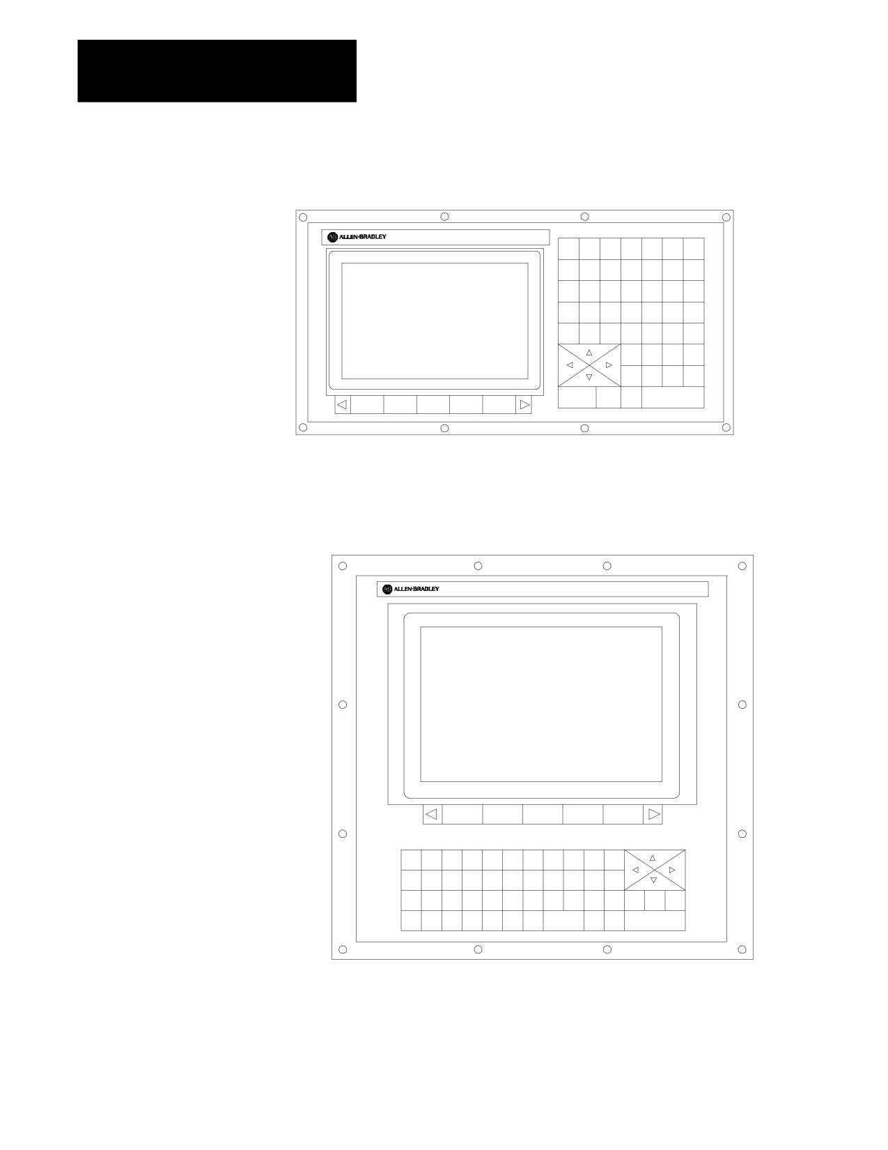
Figure 2.1 shows the monochrome operator panel. Figure 2.2 shows the
color operator panel. The color operator panel has identical keys and
softkeys in a slightly different configuration.
2-1
Chapter 2
Basic Control Operation
Figure 2.1
Monochrome Operator Panel
9/SERIES
7
8
9
O
N
G
P
4
5
6
X
Y
Z
Q
$
1
2
3
I
J
K
R
_
0
A
B
C
L
%
;
SP
+
=
:
F
D
H
#
_
!
E
?
o
M
S
T
EOB
[
]
(
)
CALC
DEL
CAN
RES
SHIFT
DISP
PROC
TRANSMIT
19435
Figure 2.2
Color Operator Panel
9/SE RIE S
7
8
9
+
O
N
G
F
D
H
#
E
?
,
_
4
5
6
X
Y
Z
A
B
C
L
$
W
SP
&
1
2
3
=
P
Q
R
M
S
T
EOB
DEL
CAN
RES
_
[
]
(
)
LINE
CNTRL
0
:
CALC
I
J
K
DISP
PROC
TRANSMIT
!
SHIFT
19436
2-2

Chapter 2
Basic Control Operation
2.1.1
Table 2.A explains the functions of keys on the operator panel keyboard.
In this manual, the names of operator panel keys appear between [ ]
Keyboard
symbols.
Table 2.A
Key Functions
Key Name
Function
Address and Numeric Keys
Use these keys to enter alphabetic and numeric
characters. If a key has two characters printed on it,
pressing it normally enters the upper left character. Holding
down the [SHIFT] key while pressing it enters the lower
right character.
Cursor Keys ‹ , ›, fi , fl
Use these keys to move the cursor left, right, up and down
in the data display area (lines 4-21) of the screen. We
refer to these keys as the left, right, up, and down cursor
keys respectively.
[SHIFT] and fi or ‹
Press the right or left cursor keys while holding down the
[SHIFT] key to move the cursor right and left on any
line on which that data is being input. (normally screen
lines 2-3).
[SHIFT] and › or fl
Press the up or down cursor key while holding down the
[SHIFT] key to roll the display page forward or
backwards.
Calculation Key [CALC]
Pressing this key enables a calculator type function on the
control. Basic mathematical expressions may be evaluated
using this feature. For details, see page 2-4 .
Delete Key [DEL]
Pressing this key deletes the character to the left of the
cursor on input lines.
[SHIFT] and [DEL]
Pressing this key deletes all keyed-in data currently
displayed on input lines.
[CAN]
Clear the most recently generated, active error message
Transmit Key [TRANSMIT]
The data entered and displayed on the input lines is sent to
the control when the [TRANSMIT] key is pressed, for
example a password or a program block.
Block Reset [RESET]
This performs a block reset. See page 2-4 .
Control Reset [RESET] +
Pressing the reset key while holding down the shift key
[SHIFT]
performs a control reset. See page 2-4 for details.
Display Select
Use this key to display the different axis position display
[DISP SELECT]
softkeys as described on page 8-1.
End of Block [E.O.B.]
Use this key to enter an End of Block character when
editing a program or when writing an MDI program.
[PROC SELECT]
This key is used for dual process lathe systems only.
Pressing this key toggles the control from process to
process. Refer to chapter 30 for details.
[SHIFT] and [fi ]
Press the [SHIFT] key while holding down the [fi ]
softkey to jump to the online search monitor screen. Press
these keys again to return to the previous screen.
2-3
Chapter 2
Basic Control Operation
Reset Operations
If you are using a dual-processing system, refer to page 30-6 for details
about reset operations.
Block Reset
Use the block reset feature to force the control to skip the block execution.
To use the block reset function, program execution must be stopped. If
program execution stops before the control has completely finished the
block execution, a block reset aborts any portion of that block that has not
been executed. If program execution stops after the complete block
execution (as in the case of single block execution or a M00 etc.), the
control aborts the execution of the entire following block.
Press [RESET] key on the operator panel to perform a block reset.
Control Reset
You can return the control to the default parameters, clear any
programming errors, and cancel any MDI commands by executing a
control reset. After you execute a control reset, any active program resets
to the first block; any programmed offsets or rotations of the coordinate
systems reset to default, and any MDI command is discarded. All of the
operating parameters return to the standard AMP-assigned values,
including any AMP-assigned G-codes active at power-up (except
Inch/Metric which remains in its last programmed state at control reset).
Press the [RESET] key on the operator panel while holding down the
[SHIFT] key to execute a control reset.
2.1.2
The 9/Series control is equipped to evaluate simple mathematical
Calculator Function
expressions during the course of operation or programming.
To use the calculator function, line 2 of the screen must be blank. There
can be no prompt on the input line of the screen when you attempt to do
calculations. This completely disables any calculation operation when in
MDI mode. If you attempt to enter the calculator function while another
prompt is active, the control generates the error message “CANNOT
CALCULATE - PROMPT PRESENT.”
Use the calculator function as follows:
1.
Press the [CALC] key on the operator panel. The “CALC:” prompt
appears on the input line of the screen (line 2).
2.
Enter a mathematical equation on the input line by pressing the
desired keys on the operator panel.
3.
Press the [TRANSMIT] key to evaluate the expression. The answer to
the expression is displayed on the input line.
2-4
Chapter 2
Basic Control Operation
Expressions entered on the input line cannot exceed a total of 25
characters. Only numeric or special mathematical operation characters as
described below can be entered next to the “CALC:” prompt. Any
character that is not numeric or an operation character you enter on the
input line generates the error message “INVALID CHARACTER.”
The largest number you can enter for a calculate function is 214748367.
You cannot enter a number larger than 10 digits. If control displays a
number that is too large (longer than 10 digits), the control displays the
error message “NUMBER IS OUT OF RANGE”. If the number entered or
calculated is greater than 10 digits, control displays the error message
“MATH OVERFLOW.”
Any fractional numbers cannot exceed .999999 (6 decimal places). If you
exceed this number of decimal places, the control automatically rounds off.
If this seventh digit is less than 5, the control rounds down. If this seventh
digit is 5 or greater, the control rounds up.
Any data entered on the input lines can be edited as described on page
2-37.
To disable the calculator function, press the [CALC] key again. The
“CALC:” prompt is removed from the input line.
Use the characters in Table 2.B to indicate mathematical operations.
Table 2.B
Mathematical Operators
Multiplication
/
Division
+
Addition
-
Subtraction
[]
Brackets
#
Get Paramacro Value
The control executes mathematical operations in this order:
1.
Any part of the expression that is between the brackets [ ] is
evaluated first. The values of paramacro variables are also
substituted for the #xxxx as the first operation performed.
2.
Multiplication and division are evaluated second.
3.
Addition and subtraction are evaluated last.
If the same level of evaluation is performed the left most operation takes
priority.
2-5

Chapter 2
Basic Control Operation
Example 2.1
Mathematic Expressions
Expression Entered
Result Displayed
12/4*3
9
12/[4*3]
1
12+2/2
13
[12+2]/2
7
12-4+3
11
12-[4+3]
5
Table 2.C lists the function commands available with the [CALC] key.
Table 2.C
Mathematical Functions
Function
Meaning
SIN
Sine (degrees)
COS
Cosine (degrees)
TAN
Tangent (degrees)
ATAN
Arc Tangent (degrees)
ASIN
Arc Sine (degrees)
ACOS
Arc Cosine (degrees)
SQRT
Square Root
ABS
Absolute Value
BIN
Conversion from Decimal to Coded Decimal
BCD
Conversion from Coded Decimal to Decimal
ROUND
Rounding Off (nearest whole number)
FIX
Truncation Down
FUP
Truncation Up
LN
Logarithms (natural log)
EXP
Exponent
When you program these functions, place the value that the function is to
be performed on in brackets, for example, SIN [10]. The exception to this
is the arc tangent function. The format for ATAN requires the division of
two values. For example, ATAN [10]/[2] is used to calculate the arc
tangent of 5.
The functions in Table 2.C are executed from left to right in a program
block. These functions are executed before the control executes any
mathematical operators like addition or subtraction. This order of
execution can only be changed by enclosing operations in brackets [ ].
Operations enclosed in brackets are executed first.
2-6
Chapter 2
Basic Control Operation
Example 2.2
Format for [CALC] Functions
SIN[2]
This evaluates the sine of 2 degrees.
SQRT[14+2]
This evaluates the square root of 16.
SIN[SQRT[14+2]]
This evaluates the sine of the square root of 16.
Example 2.3
Mathematical Function Examples
Expression Entered
Result
SIN[90]
1.0
SQRT[16]
4.0
ABS[-4]
4.0
BIN[855]
357.0
BCD[357]
855.0
ROUND[12.5]
13.0
ROUND[12.4]
12.0
FIX[12.7]
12.0
FUP[12.2]
13.0
FUP[12.0]
12.0
LN[9]
2.197225
EXP[2]
7.389056
Important: Precaution must be taken when performing calculations within
the brackets [ ]. The operations within the bracket are performed first, and
then the function is performed on this resultant. For example:
ROUND[2.8+2.6];
The result of this is 5.0
The values in the brackets are added together first and then rounded, not
rounded and then added together.
Paramacro Variables in CALC Operations
Any paramacro variable can be accessed through the CALC function.
Include a # sign followed by the paramacro variable number. When the
calculation is performed the value of that paramacro variable is substituted
into the equation. You can not change the value of paramacro variables
with the CALC function. Local parameters are only available for the
currently active nesting level of the control (main program, or one of four
nested macro programs). You can not perform calculations that contain
any paramacro variables if the control is currently executing a program
block. The control must be in either cycle stop state, or E-Stop.
2-7
Chapter 2
Basic Control Operation
Example 2.4
Calling Paramacro Variables with the CALC Function
Expression Entered
Result Displayed
#100
Display current value of variable #100
12/#100*3
Divide 12 by the current value of #100
and multiply by 3
SIN[#31*3]
Multiply the value of #31 (for the current
local parameter nesting level) by 3 and
take the sine of that result
2.1.3
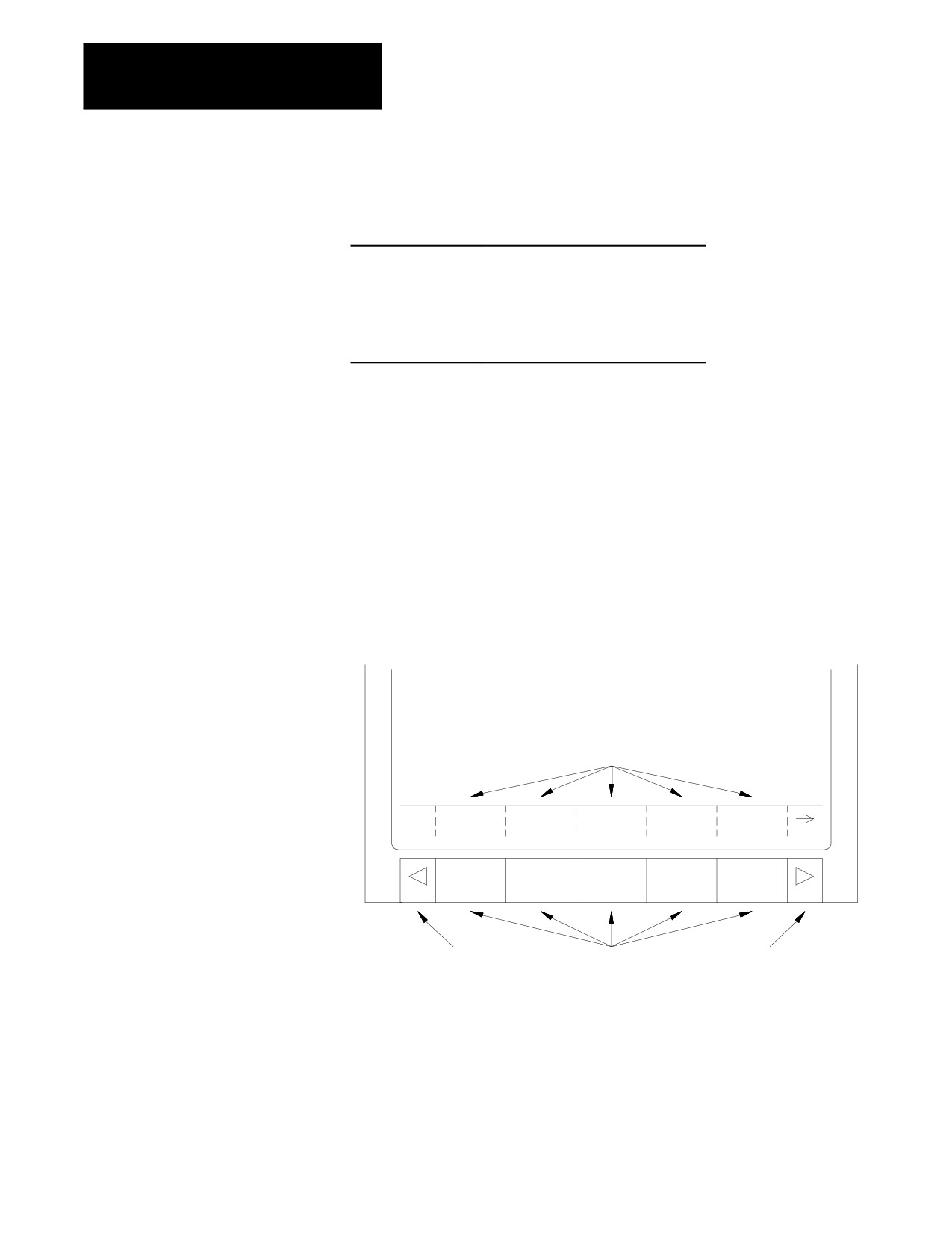
We use the term softkey to describe the row of 7 keys at the bottom of the
CRT. Each function is displayed on the CRT directly above the softkey.
Softkeys
Softkey names are shown between the { } symbols in this manual.
The control offers a variety of functions that can be initiated by using the
softkeys. The operator panel has 5 softkeys whose function names are
displayed in the softkey area at the bottom of the screen (lines 23-25 — see
Figure 2.3).
Figure 2.3
Softkeys
Data display area
Softkey name display area
PRGRAM
OFFSET
MACRO
PRGRAM SYSTEM
MANAGE
PARAM
CHECK
SUPORT
Exit
Softkeys
Continue key
We often describe softkeys as being on a certain level, for example softkey
level 3. We use the level of the softkey to determine the location or
necessary path to reach that particular softkey function. For example, to
get to a softkey on level 3, you must press a specific softkey on level 1,
followed by a specific softkey on level 2. For a listing of all the softkeys
and their respective levels, refer to appendix A.
2-8