9/Series CNC Lathe. Operation and Programming Manual - page 3
Chapter 2
Basic Control Operation
To reformat control memory and delete all programs stored in memory,
follow these steps:
1.
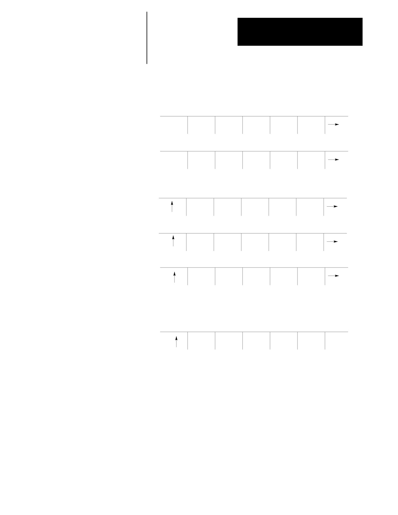
Press the {PRGRAM MANAGE} softkey.
(softkey level 1)
PRGRAM
OFFSET
MACRO
PRGRAM
SYSTEM
MANAGE
PARAM
CHECK
SUPORT
FRONT
ERROR
PASS-
SWITCH
PANEL
MESAGE
WORD
LANG
2.
Press the {REFORM MEMORY} softkey.
(softkey level 2)
ACTIVE
EDIT
RESTRT
DISPLY
COPY
PRGRAM
PRGRAM
PRGRAM
PRGRAM
PRGRAM
DELETE
VERFY
PRGRAM
RENAME
INPUT
PRGRAM
PRGRAM
COMENT
PRGRAM
DEVICE
REFORM
CHANGE
MEMORY
DIR
3.
Press the {REFORM YES} softkey. All programs that are stored in
control memory are deleted. To abort the operation, press the
{REFORM NO} softkey.
(softkey level 3)
REFORM
REFORM
YES
NO
It can take several seconds for the control to complete the operation.
During this period, the softkeys on the operator panel are rendered
inoperative.
2-39
Chapter 2
Basic Control Operation
2.12
This feature allows the removal of a rotary table or other axis attachment
from a machine. When activated, the control ignores messages that may
Removing an Axis
occur resulting from the loss of feedback from a removed axis such as
(Axis Detach)
servo errors, etc.
Important: This feature removes the selected axis from the control as an
active axis. Any attempt to move the removed axis results in an error.
This means that part programs that use the removed axis name cannot be
executed. Jog moves and MDI commands that attempt to move the
removed axis also result in an error.
This feature can be enabled in AMP. The axis must be selected as
“Detached” to be considered removed. Refer to the documentation
supplied by your system installer for the necessary steps involved in
detaching an axis or physically removing axis hardware from your
machine.
2.13
The Time Parts Count Display logs data relevant to part program execution
such as number of workpieces cut, cycle time, lot size, and remaining
Time Parts Count
workpieces. This data can be displayed and altered through the Time Parts
Display Feature
screen.
There are 3 levels of access to the Time Parts screen. They are listed
below in order of most restrictive to least restrictive. Refer to page 2-23
for details on password protection and access control.
Access:
Protection:
No
Restricts operator from Time Parts screen entirely (softkey
{TIME PARTS} not accessible). Accomplished by denying access to
“Active Program.”
Operator
Restricts operator from setting “Date”or “Time”(softkeys {SET TIME}
and {SET DATE} do not appear). Also restricts operator from setting
“Power-on time/overall”and “Workpieces cut/overall.” Accomplished by
denying access to “Time Parts.”
Supervisor
Full access to all features of the Time Parts screen.
To access the Time Parts screen, follow these steps:
1.
Press the {PRGRAM MANAGE} softkey.
(softkey level 1)
PRGRAM
OFFSET
MACRO
PRGRAM
SYSTEM
MANAGE
PARAM
CHECK
SUPORT
FRONT
ERROR
PASS-
SWITCH
PANEL
MESAGE
WORD
LANG
2-40
Chapter 2
Basic Control Operation
2.
Press the {ACTIVE PRGRAM} softkey.
(softkey level 2)
ACTIVE
EDIT
RESTRT
DISPLY
COPY
PRGRAM
PRGRAM
PRGRAM
PRGRAM
PRGRAM
DELETE
VERFY
PRGRAM
RENAME
INPUT
PRGRAM
PRGRAM
COMENT
PRGRAM
DEVICE
REFORM
CHANGE
MEMORY
DIR
3.
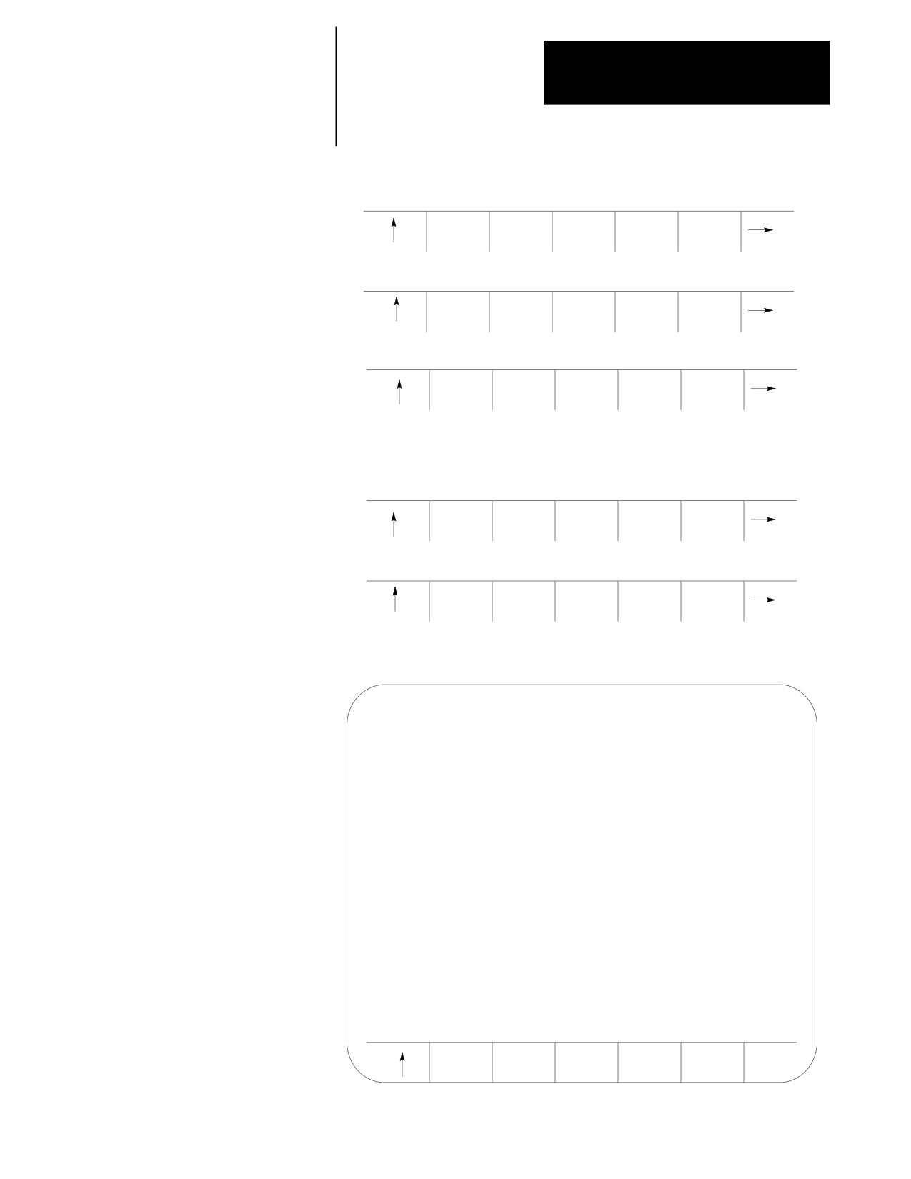
Press the {TIME PARTS} softkey. This generates the screen shown in
Figure 2.11.
(softkey level 3)
DE-ACT
SEARCH
MID ST
T PATH
T PATH
PRGRAM
PRGRAM
GRAPH
DISABL
SEQ
TIME
STOP
PARTS
Figure 2.11
Time Parts Screen
PROGRAM
DATE
TIME
XXXXXXXX
MM/DD/YY
HH:MM:SS
POWER-ON TIME/OVERALL
:
99999:59:59
WORKPIECES CUT/OVERALL
:
9999999999
RUN TIME
:
99999:59:59
POWER-ON TIME/AFTER RESET
:
99999:59:59
CYCLE TIME
:
99999:59:59
WORKPIECES CUT/AFTER RESET
:
9999999999
LOT SIZE
:
9999999999
REMAINING WORKPIECES
:
999999999
LOT COMPLETION FLAG
:
0
(PAL messages)
SET
SET
ED PRT
TIME
DATE
INFO
2-41
Chapter 2
Basic Control Operation
Important: Some softkeys shown in Figure 2.11 might not appear on your
system due to restricted access. Refer to the beginning of this section and
page 2-23 for details.
You can modify the values on this screen. Press the {ED PRT INFO},
{SET DATE}, or the {SET TIME} softkeys as explained in the Screen Field
Definitions that follow.
Press the exit softkey {›} to save changes and return to the “Active
Program” screen.
Time Part Screen Field Definitions
Program -- is the currently active part program, displayed automatically
by the control.
Date -- is the current date setting. To change this setting:
1.
Press the {SET DATE} softkey, provided that you have
supervisor-level access.
You are prompted for a new date with a line that displays the current
date setting.
2.
Press the [DEL] key to erase the characters displayed.
3.
Type in the new date.
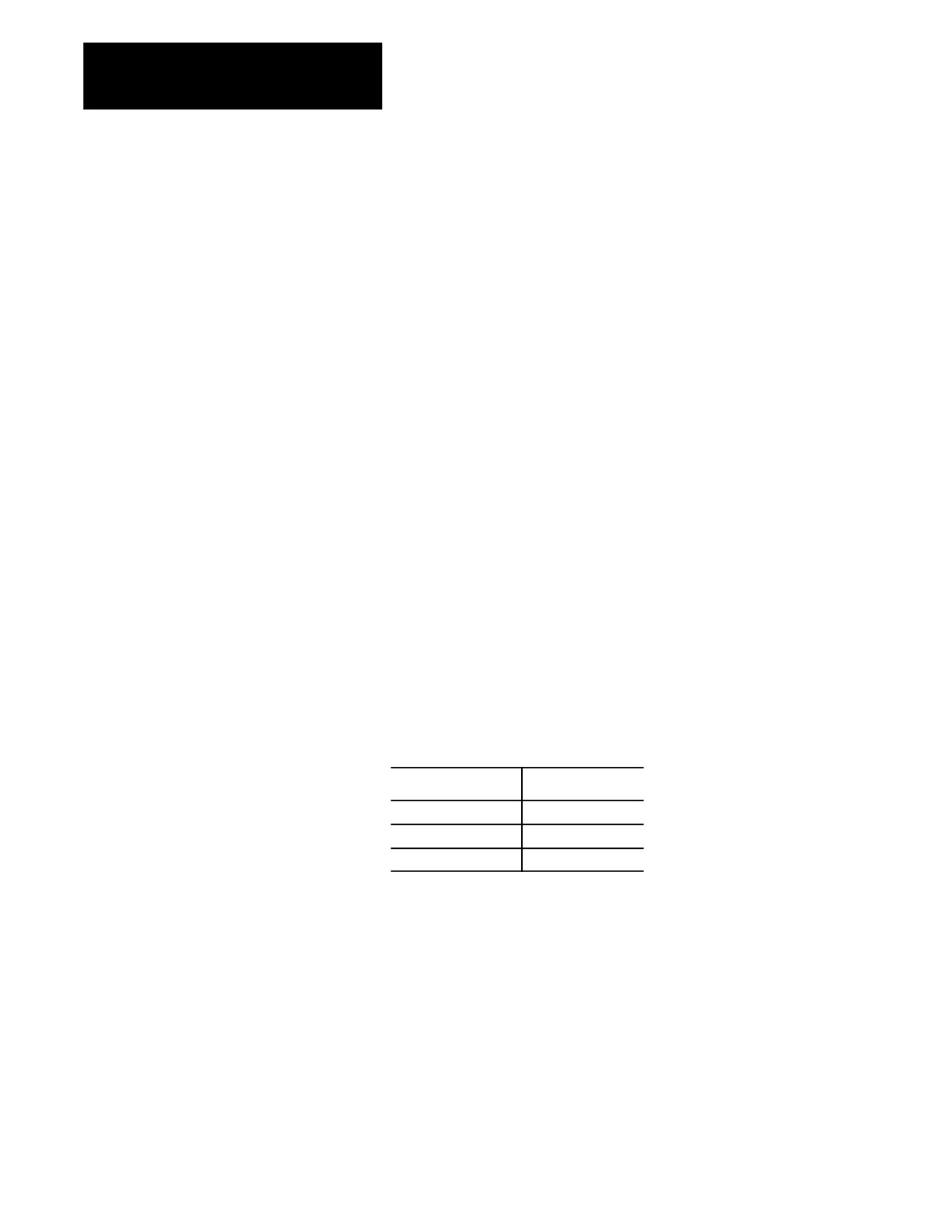
You must use one of these formats:
Format:
Language:
Month / Day / Year
English
Year / Month / Day
Japanese
Day / Month / Year
German
Time -- is the current 24-hour time setting. It can be changed by pressing
the {SET TIME} softkey, provided that you have supervisor-level access.
You are prompted for a new time with a line that displays the current time
setting. Change the current setting by pressing the [DEL] key to erase the
characters displayed and then typing in the new time. You must enter
using the format Hours:Minutes:Seconds. For example, 2:00 pm should be
entered as 14:00:00.
2-42
Chapter 2
Basic Control Operation
Power-on Time/Overall -- indicates the total accumulated time that the
control has been ON. This value is saved in backup memory each time the
control is powered off, so it is restored at its previous value each time the
control is turned ON. To clear this field to zero:
1.
Press the {ED PRT INFO} softkey, provided that you have
supervisor-level access.
2.
Press the up or down cursor keys to move to this field or the next
field without changing the current value.
3.
Enter a Y at the prompt for this field.
4.
Press [TRANSMIT] to clear the current value.
Workpieces Cut/Overall -- indicates the total number of part programs
executed to completion by the control. Use this field to determine the need
for periodic checkups or as a statement of warranty. This counter is
incremented by one each time the control encounters an M02, M30, or an
M99 in a main part program (M99 in a subprogram does not increment this
counter, though M02 or M30 does). To clear this field to zero:
1.
Press the {ED PRT INFO} softkey, provided that you have
supervisor-level access.
2.
Press the up or down cursor keys to move to this field or the next
field without changing the current value.
3.
Enter a Y at the prompt for this field.
4.
Press [TRANSMIT] to clear the current value.
Run Time -- indicates the total accumulated time that part programs were
executing with the control in automatic mode. Use this field with
“Power-on Time/After Reset” to estimate the utilization ratio of the
machine. To clear this field to zero:
1.
Press the {ED PRT INFO} softkey if you have either operator-level or
supervisor-level access.
2.
Press the up or down cursor keys to move to this field or the next
field without changing the current value.
3.
Enter a Y at the prompt for this field.
4.
Press [TRANSMIT] to clear the current value.
2-43
Chapter 2
Basic Control Operation
Power-on Time/After Reset -- indicates the total accumulated time that
the control has been ON. This value is saved in backup memory each time
the control is powered off, so it is restored at its previous value each time
the control is turned ON. Use this field with “Run Time” to estimate the
utilization ratio of the machine. The value for this field is cleared to zero
when the “Run Time” field is cleared to zero; it cannot be changed
independently.
Cycle Time -- indicates the elapsed execution time for each individual part
program. Cycle time begins counting when the cycle-start button is
pressed and ends when an M02 reset or M30 is encountered. To reset this
field to zero, use one of three methods:
press the cycle-start button to initiate program execution
turn off the control power
follow these steps:
1.
Press the {ED PRT INFO} softkey if you have either operator-level or
supervisor-level access.
2.
Press the up or down cursor keys to move to this field or the next
field without changing the current value.
3.
Enter a Y at the prompt for this field.
4.
Press [TRANSMIT] to clear the current value.
Workpieces Cut/After Reset -- indicates the total number of part
programs executed to completion by the control since the last time “Run
Time” was reset. This counter is incremented by one each time the control
encounters an M02, M30 or an M99 in a main part program (M99 in a
subprogram does not increment this counter, though M02 or M30 does).
The value for this field is cleared to zero when the “Run Time” field is
cleared to zero; it cannot be changed independently.
Lot Size -- is the number of times you need to execute this particular part
program. To enter a new number:
1.
Press the {ED PRT INFO} softkey if you have either operator-level or
supervisor-level access.
2.
Press the up or down cursor keys to move to this field or the next
field without changing the current value.
3.
Enter a numeric value at the prompt for this field.
4.
Press [TRANSMIT] to change the current value.
2-44
Chapter 2
Basic Control Operation
Remaining Workpieces -- indicates the number of workpieces that still
need to be cut in the lot. The value for this field is automatically set equal
to the lot size each time the “Lot Size” value is changed. When the control
encounters an M02, M30, or M99 in a main part program, the remaining
workpieces field is decremented by one. The control tells the system
installers PAL program when the lot remaining size is zero. At this point,
press <CYCLE START> to automatically set the field back to the “Lot Size”
value. Complete operation of this feature is somewhat PAL dependant.
Refer to the documentation supplied by your system installer.
Lot Completion Flag -- is automatically set to zero by the control
whenever a non-zero value is entered for “Lot Size.” It is set to one when
the “Remaining Workpieces” field reaches zero. It is again reset to zero
when the next cycle start occurs after the remaining workpieces field has
reached zero. Complete operation of this feature is somewhat PAL
dependant. See the documentation supplied by your system installer.
Press the exit softkey {›} to save changes and return to the “Active
Program” screen.
END OF CHAPTER
2-45
Chapter
3
Offset Tables and Setup
3.0
In this chapter we describe the basics for job setup. Major topics include:
Chapter Overview
Topic:
On page:
Changing the active tool offset
3-14
Work coordinate system offset table
3-15
Backing up offset tables
3-19
Programmable zone table
3-21
Single--digit feedrate table
3-23
3.1
Use tool offsets to let the programmer always write a part program with
respect to the same point on the machine regardless of the tool being used.
Tool Offset Tables
Tool lengths are taken into account using tool length offsets as described in
{TOOL GEOMET} and
chapter 20. The radius of the tool tip and tool orientation in the turret are
{TOOL WEAR}
taken into account using TTRC as described in chapter 21. This section
describes entering these values that are called later when the corresponding
offset is activated.
Tool offsets are divided into two tables:
Tool Geometry Table - This table is typically used to enter tool data for
a brand new tool just being installed or replaced.
Tool Wear Table - This table is typically used to record slight changes
that occur to a tools shape during normal usage. Since the tools basic
orientation does not change, no orientation data may be entered into this
table.
When offset data is called in a part program, the control subtracts the value
called from the wear table from the value called from the tool geometry
data table. The result is used as the offset data for that tool. Typically
when a new tool is installed, the wear offset value is zero. As the tool gets
older, the wear value is increased.
3-1
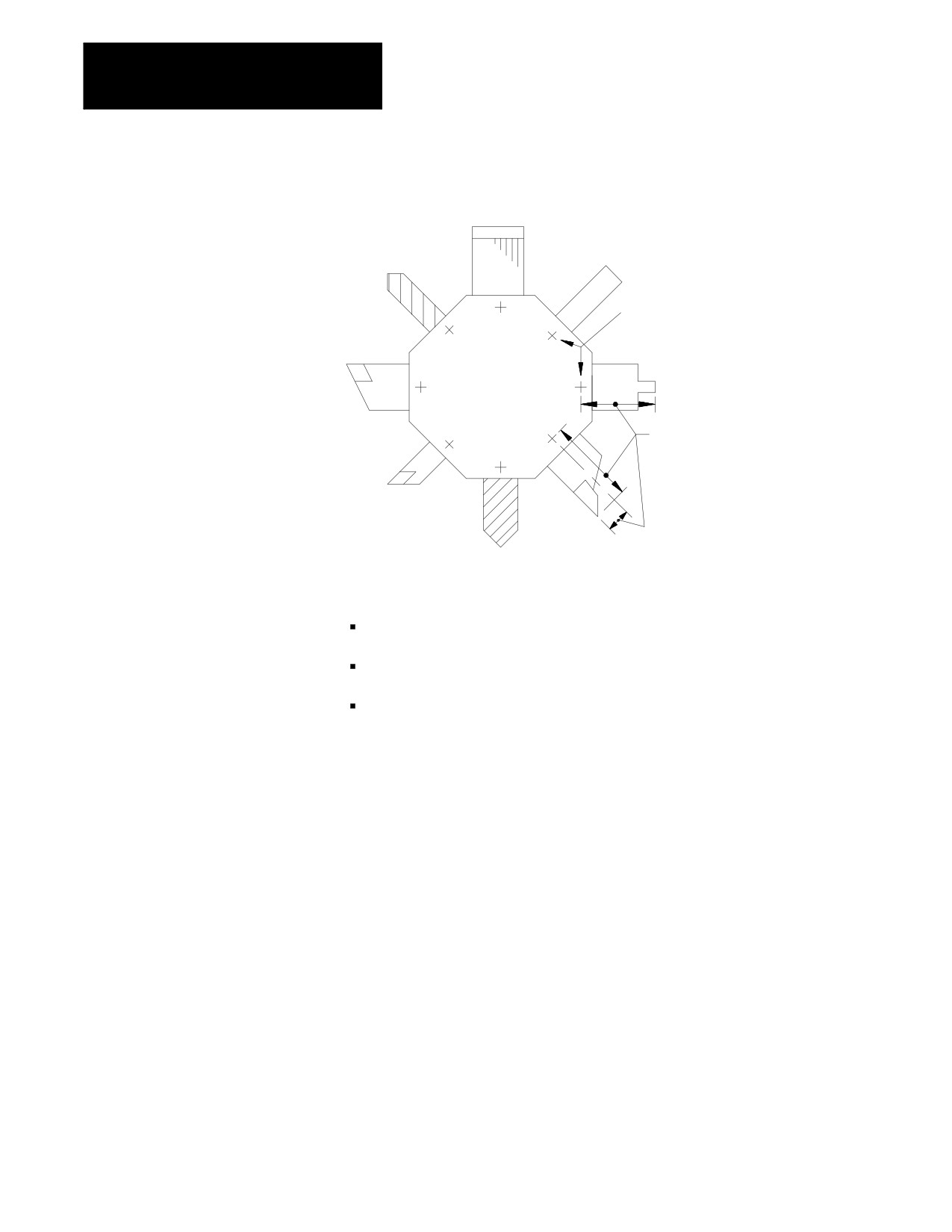
Chapter 3
Offset Tables and Setup
Figure 3.1
Tool Offset
Tool gauge points on turret
from which tool offsets are
usually measured
Tool offset values simplify
programming and allow
processing with different
tools without changing
the part program
You can enter this data into the tool offset tables:
Tool length offset data {TOOL GEOMET} and {TOOL WEAR}
Tool tip radius data {TOOL GEOMET} and {TOOL WEAR}
Tool orientation data {TOOL GEOMET}
Parameters for the resolution of the offset data are determined by the
system installer in AMP. The range available to the system installer is 0.01
to 0.00001 mm (0.001 to 0.000001 inch) with a maximum number of 8
digits.
Tool Offset Numbers
Use a T-word to call out tool offset numbers in a program. The T-word
specifies a one, two, or three-digit offset number. The control then
accesses the values assigned to that offset number in the table. Offsets are
activated as described in the sections on that specific type of offset.
For more information on calling offset numbers, refer to chapter 20.
Offset number “00” is not valid, but can be used to cancel tool offsets.
Different offset numbers may be called from the tool geometry and tool
wear table using the same T-word (depending on the T-word type selected
in AMP). This means that wear offset data corresponding to offset number
1 may not need to correspond to tool geometry offset number 1, etc.
3-2
Chapter 3
Offset Table and Setup
3.1.1
Tool Dimensional
Parameters
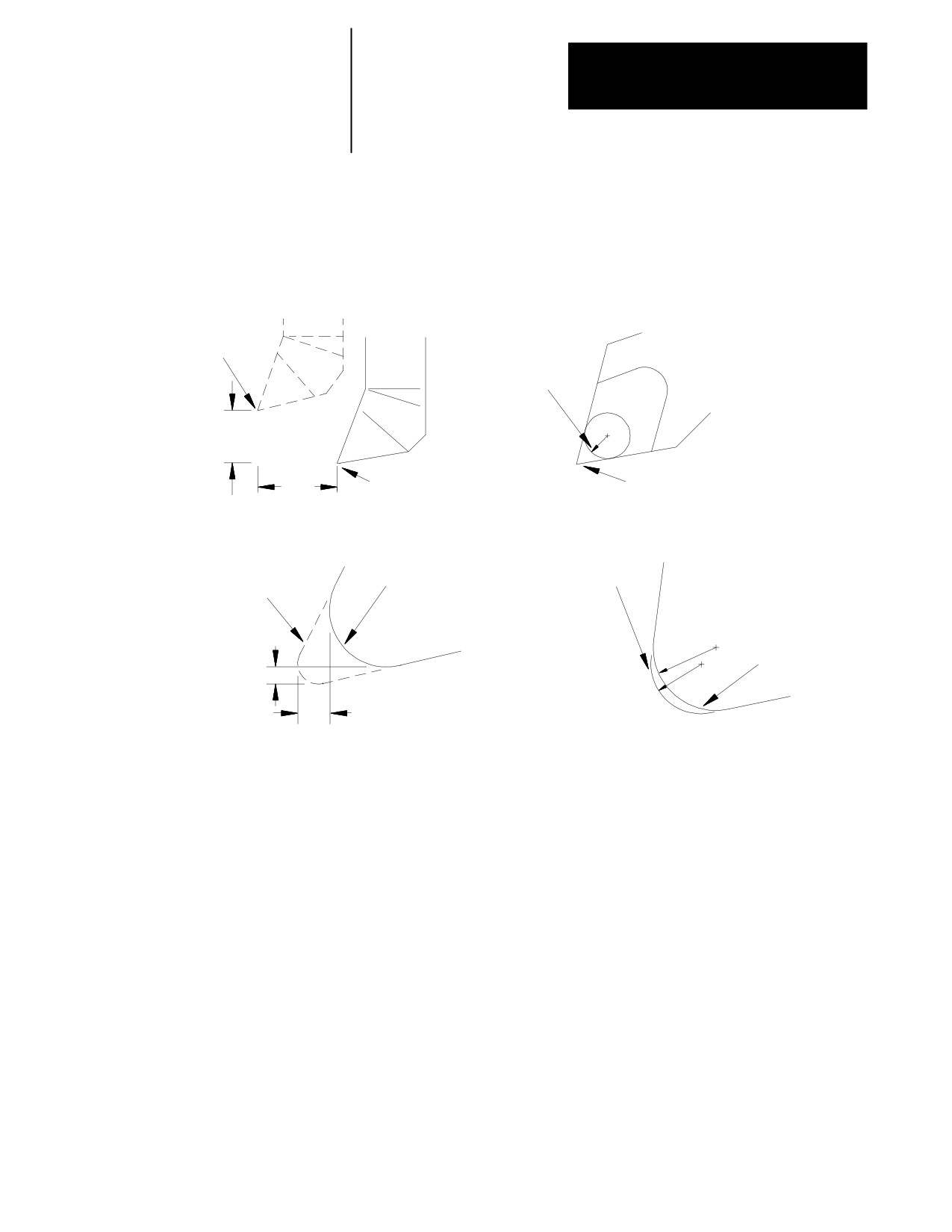
Figure 3.2
Tool Dimensional Offsets
TOOL GEOMETRY, LENGTH
TOOL GEOMETRY, TIP RADIUS
Assumed tool
position
Actual tool
tip point
R
X
Actual tool
Assumed tool
Z
position
tip point
TOOL WEAR, LENGTH
TOOL WEAR, RADIUS
Cutting edge before
Worn cutting
Cutting edge before
tool wear
edge
tool wear
R = R’- R
X/2
R’
Worn cutting
R
edge
Z
Tool Length (Tool Geometry Table)
The dimensions, entered into the tool geometry for length, reflect the
distance from the tool tip to the gauge point on the tool holder. This gauge
point actually moves to the coordinates programmed in a part program, if a
tool offset is not activated.
We use the term “gauge point” to define the precise point on the turret
from which all programmed tool paths originate. Offsets refer to the
distance from this gauge point to the tip or edge of the tool that contacts
the part being cut.
Use the tool length offset function to compensate for the difference
between the tool position as mounted in the turret and the tool position
assumed in writing a program. By using the tool length offset functions
along with tool orientation data, a programmer can write a part program
without further concern for tool position due to mounting. Measure offset
values for each axis to allow for the difference between the assumed and
actual cutting tool locations.
3-3
Chapter 3
Offset Tables and Setup
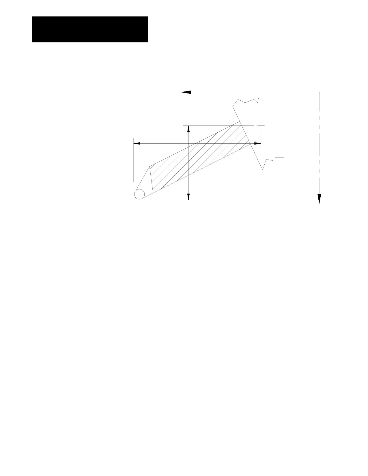
Figure 3.3
Tool Length Offsets
-Z
Gauge point
Z tool offset
X tool offset (entered
as a diameter value)
-X
The Z offset table value corresponds to the actual Z distance from the tool
tip to the gauge point. The X offset value is the distance on the axis from
the tool tip to the gauge point. Consequently, when the control activates a
tool offset, the Z axis is displaced per the table value, while the X axis is
displaced half the table value.
Generally machines are configured such that axes move in the negative
direction as they move the tool turret towards the workpiece (this refers to
the main or A turret if a two turret lathe). In that case, if the installed tool
protrudes in the negative direction its offset value is entered as positive.
The tool illustrated in Figure 3.3, for example, extends in both the -X and
-Z directions, so its X and Z offsets would be entered as positive. This
holds true regardless of which turret the tool is on.
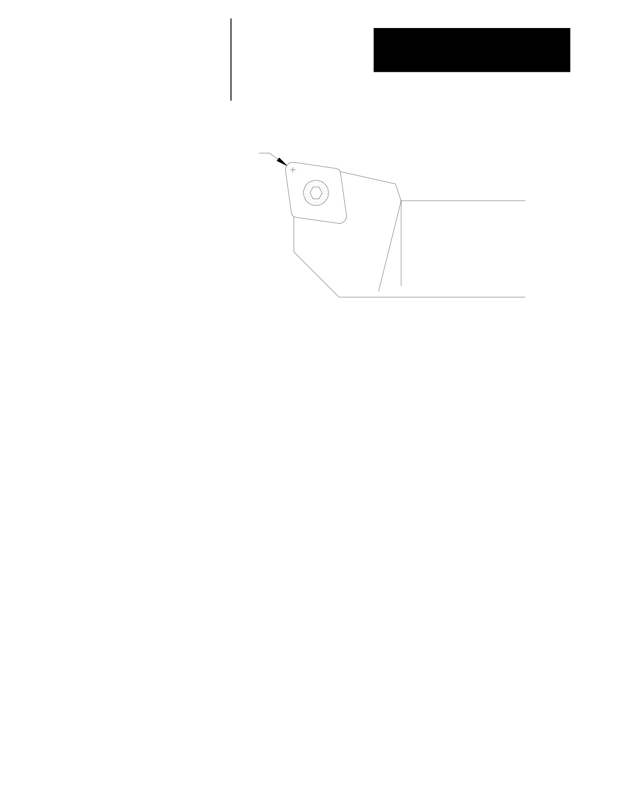
Tool Tip Radius - TTR (Tool Geometry Table)
The control can compensate for any cutting error resulting from slight or
even large rounding of the cutting tool tip. To do so, the radius of the
cutting tool tip must be entered as the geometry data for tool tip radius
compensation. For more information, refer to chapter 21.
3-4
Chapter 3
Offset Table and Setup
Figure 3.4
Tool Tip Radius for Typical Lathe Tool
.05
Radius
Tool Length (Wear Table)
The tool length wear compensation offset takes into account the wear that a
tool incurs from normal usage. Enter a value in the table that is equal to
the difference between the tool tip positions, before and after tool wear.
Tool Tip Radius Compensation - TTRC (Wear Table)
The tool tip radius wear compensation offset takes into account the normal
wear that a tool tip incurs from normal usage. Enter a value in the table
that is equal to the difference between the tool tip radius before and after
tool wear. Tool tip radius wear compensation is factored into both the X
and Z axes.
3-5
Chapter 3
Offset Tables and Setup
3.1.2
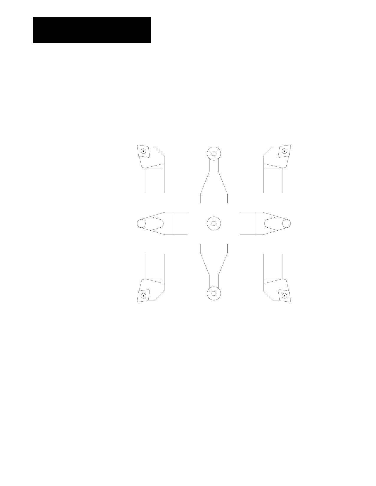
ORNT - Tool Orientation (Tool Geometry Data Table)
Tool Orientation Parameters
The control uses the value entered here to determine the orientation of the
tool’s cutting edge relative to the surface of the part. This is necessary for
the control to perform TTRC correctly. Refer to chapter 21.
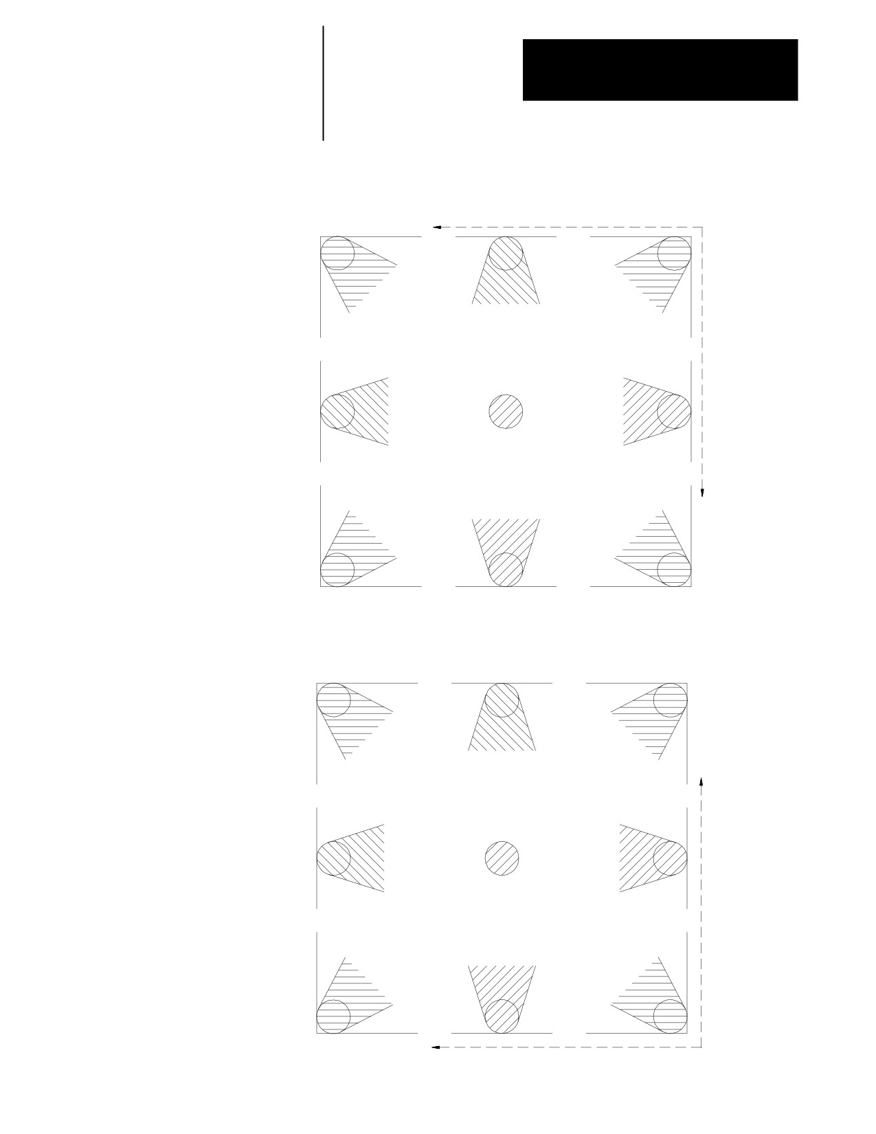
Figure 3.5
Tool Orientations for Rear Turret Lathe
2
1
6
0 or 9
7
5
3
8
4
The control uses the value entered here to determine the orientation of the
tool when Tool Tip Radius Compensation is active. Each tools’orientation
should be determined from Figure 3.5 and Figure 3.6 and its number
entered (0-9) on the geometry offset table for the ORNT parameters. From
that information the control can keep track of the orientation of the tool
currently being used and help catch some programming errors.
3-6
Chapter 3
Offset Table and Setup
Figure 3.6
Tool Orientations, Rear Turret Lathe
(Both A and B Turrets if Two-Turret Lathe)
-Z
2
1
6
7
5
9 or 0
-X
8
3
4
Figure 3.7
Tool Orientations, Front Turret Lathe
(Both A and B Turrets if Two-Turret Lathe)
3
4
8
-X
7
5
9 or 0
6
2
1
-Z
3-7
Chapter 3
Offset Tables and Setup
3.1.3
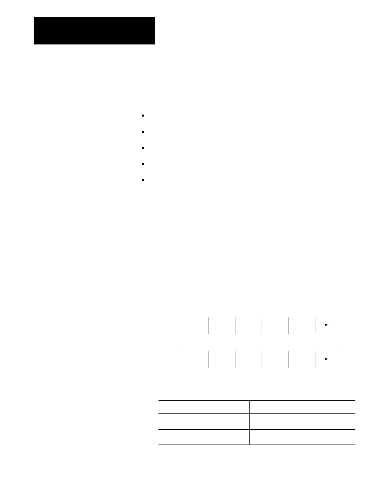
You can set data in the offset tables by using one of six methods. The
method described here requires that the offset data is manually measured
Setting Tool Offset Tables
and then directly keyed into the table. The other five methods are
described in these sections:
Using {MEASURE} (page 3-11)
Programming G10s (chapter 20)
Skip functions (chapter 27)
Setting paramacro system parameters (chapter 28)
Altering through the PAL program (refer to the 9/Series CNC PAL
Reference Manual)
When you use PAL to modify either the work coordinate system
tables or the tool offset tables, tool tip radius compensation should not
be active (G40 mode). If tool tip radius compensation is active, be
aware that the new offset is not placed in part program set-up buffers
that have already been read into control memory. This results in the
offset not being activated until several program blocks after the
current block. The number of setup buffers is dependent on the
number of block retrace steps configured in AMP and what software
features are currently being used.
To manually display or alter the offset tables, follow these directions:
1.
Press the {OFFSET} softkey.
(softkey level 1)
PRGRAM
OFFSET
MACRO
QUICK
SYSTEM
MANAGE
PARAM
CHECK
SUPORT
FRONT
ERROR
PASS-
SWITCH
PANEL
MESAGE
WORD
LANG
2.
Decide whether you want to display the tool geometry offsets or the
tool wear offsets.
To display:
Press:
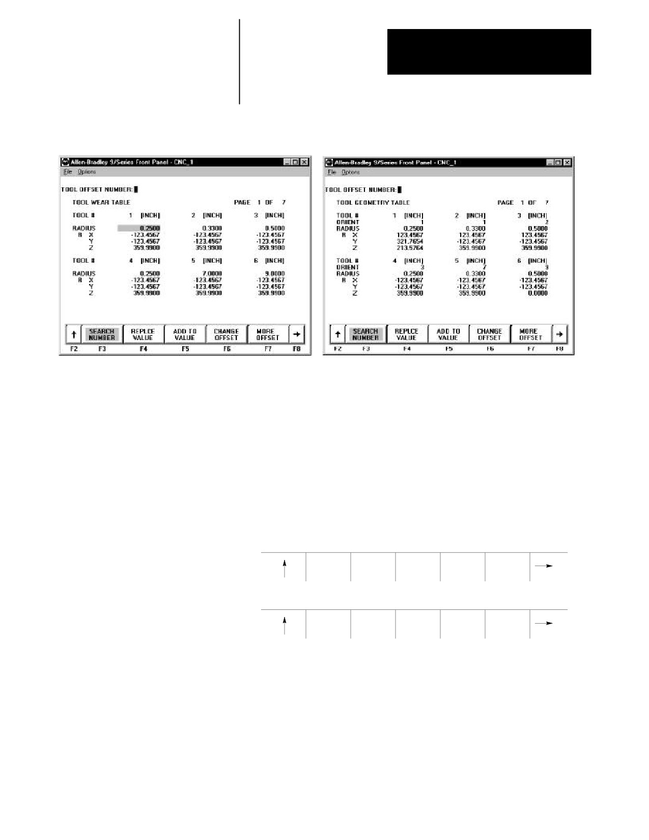
the geometry offsets (tool length offsets,
{TOOL GEOMET} softkey. Figure 3.8 shows
the tool radius, and tool orientation)
examples of tool offset screens.
the wear offsets (tool length and radius
{TOOL WEAR} softkey. Figure 3.8 shows
wear data)
examples of tool offset screens.
3-8
Chapter 3
Offset Table and Setup
Figure 3.8
Tool Offset Screens
Tool Wear Table
Tool Geometry Table
3.
Move the cursor to the offset data to be modified. Use the up, down,
left, or right cursor keys to move the block cursor to the tool offset
data on the current page. Press the {MORE OFFSET} softkey to change
pages.
To search all pages for a specific offset number, press the {SEARCH
NUMBER} softkey and key in the desired offset number. When you
press the <TRANSMIT> key, the control locates the cursor at the offset
number you are searching for. The tool offset data located at the
cursor appears in reverse video.
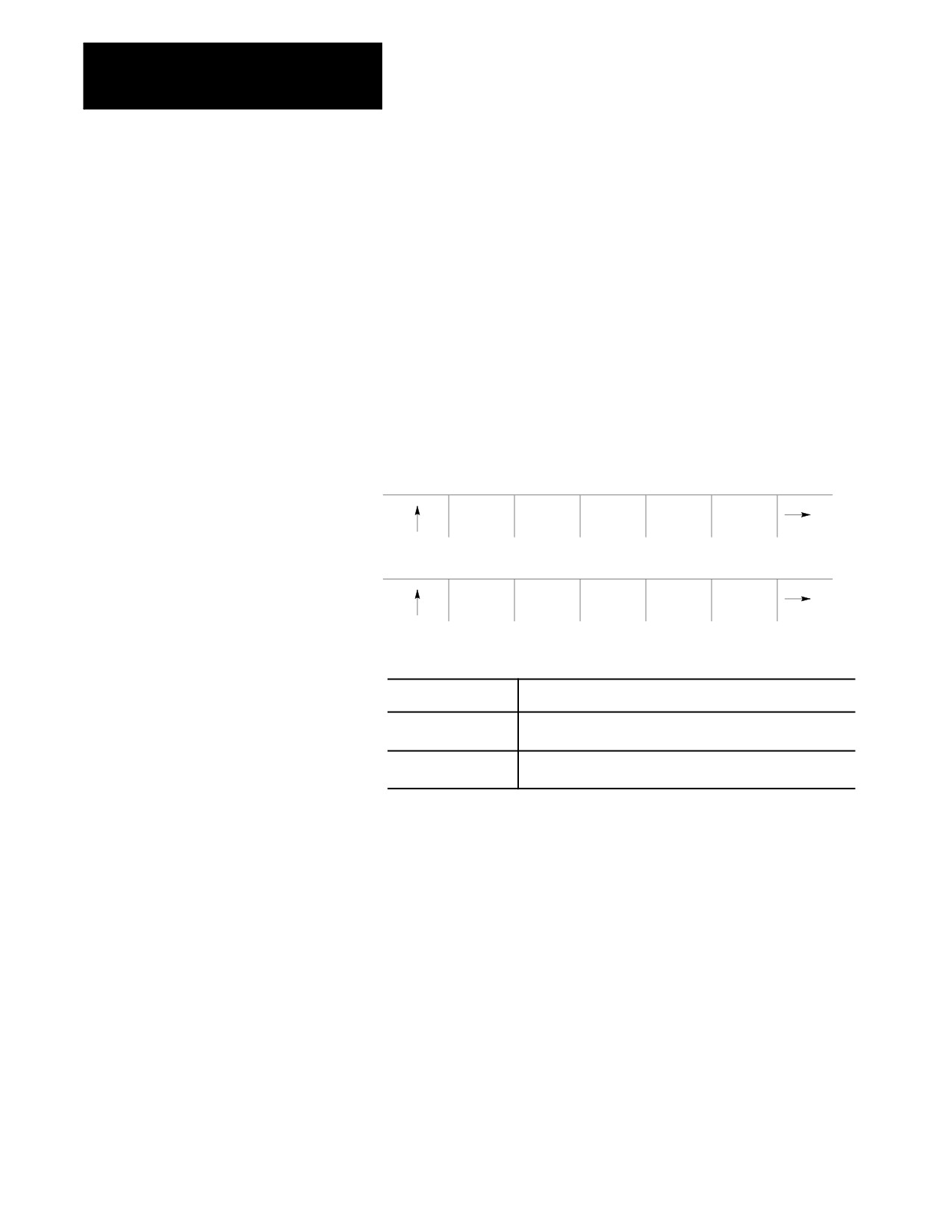
(softkey level 3)
SEARCH
REPLCE
ADD TO
ACTIVE
MORE
NUMBER
VALUE
VALUE
OFFSET
OFFSET
MEAS-
INCH/
RADI/
COPY
URE
METRIC
DIAM
OFFSET
4.
Select data entry type:
Unit selection {INCH/METRIC}
To select units of “mm” or “inch” for the offset data, press the
{INCH/METRIC} softkey. The units used for the currently selected
offset number change each time the softkey is pressed. When the
units are altered, all data previously entered is converted to the newly
selected units (Inch or Metric) for that offset number.
3-9
Chapter 3
Offset Tables and Setup
Diameter or Radius {RADI/DIAM}
If the offset value being changed has been selected in AMP as the
diameter axis (typically the axis perpendicular to the spindle center
line), data may be entered into the offset table as either a radius or
diameter value. The current mode for this axis is displayed with an R
for radius or a D for diameter mode next to that axes offset. Pressing
the {RADI/ DIAM} softkey toggles the offset between these two
modes.
This softkey does not change the current mode of control operation
(as selected with G07 or G08); it only alters how data is entered into
the table. For details on radius or diameter mode, refer to chapter 13
(G07/G08).
(softkey level 3)
SEARCH
REPLCE
ADD TO
ACTIVE
MORE
NUMBER
VALUE
VALUE
OFFSET
OFFSET
MEAS-
INCH/
RADI/
COPY
URE
METRIC
DIAM
OFFSET
5.
Enter offset data; replace or add data as follows:
Press this softkey:
Then:
{REPLCE VALUE}
Type in the new value. Press the [ENTER] key. The new
value replaces the old value for that feedrate.
{ADD TO VALUE}
Type in the number. Press the [ENTER] key. The new value
is added to the old value for that area.
If desired, stored offset data can be copied from one axis to another
axis for all offset numbers (rather than having to change each axis
individually).
A. Press the {COPY OFFSET} softkey.
B. “COPY (SOURCE, DESTINATION):”appears. Enter the axis
letter from which the data is coming, then a comma, and then
enter the axis letter to which the data is going. For example,
COPY (SOURCE, DESTINATION): X,Z
copies the offset data from the X axis to the Z axis for all offset
numbers.
3-10
Chapter 3
Offset Table and Setup
3.1.4
The measure feature offers an easier method of establishing tool offsets.
The control, not the operator, computes the tool length and wear offsets,
Setting Offset Data Using
and enters these values into the tool offset tables. The measure feature is
{MEASURE}
used to measure tool length offset values for the wear or geometry tables; it
should not be used to modify tool diameter offsets.
To enter tool offsets using measure, follow these steps:
1.
Establish a fixed machine position without a tool in the tool holder.
This position can be any fixed, nonmovable location on the machine
that the tool can be jogged against consistently using a variety of
different tools.
If you enter:
Then:
a tool length in the
jog the machine gauge line (on the axis being updated) to this
geometry offset table
position. The value of this position, located in the work
coordinate system, must be recorded. The user keys in this
value in steps 6 and 7. No tool offsets should be active and no
tool should be in the tool holder.
a tool length wear in the
jog the machine gauge line to the fixed position. Add the
wear offset table,
original tool length offset from the tool geometry table to the
fixed machine location. The user keys in this value in step 7.
No tool offsets should be active and no tool should be in the
tool holder. The value of this position, located in the work
coordinate system, must be recorded.
2.
Access the tool geometry or wear offset table.
3.
Cursor down to the offset that you want to change. The offset can be
displayed in either inch or metric measurements.
4.
Load the tool that you want to measure into the tool holder.
5.
Using incremental, continuous or handwheel mode, jog the tool tip to
the fixed location determined in step 1.
6.
Press the {MEASURE} softkey.
7.
Key in the coordinate value of the fixed location determined in step 1.
8.
Press the [ENTER] key.
The control now subtracts the keyed in position from the current tool
position and enters this difference as the offset value into the table.
3-11
Chapter 3
Offset Tables and Setup
3.1.5
Tool offset range verification checks:
Tool Offset Range
the maximum values entering the tool offset tables
Verification
the maximum change that can occur in either table
To use tool offset range verification, follow this softkey sequence:
1.
Press the {SYSTEM SUPORT} softkey.
(softkey level 1)
PRGRAM
OFFSET
MACRO
PRGRAM
SYSTEM
MANAGE
PARAM
CHECK
SUPORT
FRONT
ERROR
PASS-
SWITCH
PANEL
MESAGE
WORD
LANG
2.
Press the {AMP} softkey.
(softkey level 2)
PRGRAM
AMP
DEVICE
MONI-
TIME
PARAM
SETUP
TOR
PARTS
PTOM
SYSTEM
SI/OEM
TIMING
3.
Press the {AXIS PARAM} softkey.
(softkey level 3)
AXIS
PATCH
UPDATE
UPLD/
BACKUP
PARAM
AMP
BACKUP
DWNLD
AMP
4.
Press the {RANGE PARAM} softkey.
(softkey level 4)
SPNDL
SERVO
AXIS
HOME
REVERS
PARAM
PARAM
CALIB
CALIB
ERROR
RANGE
PARAM
3-12
Chapter 3
Offset Table and Setup
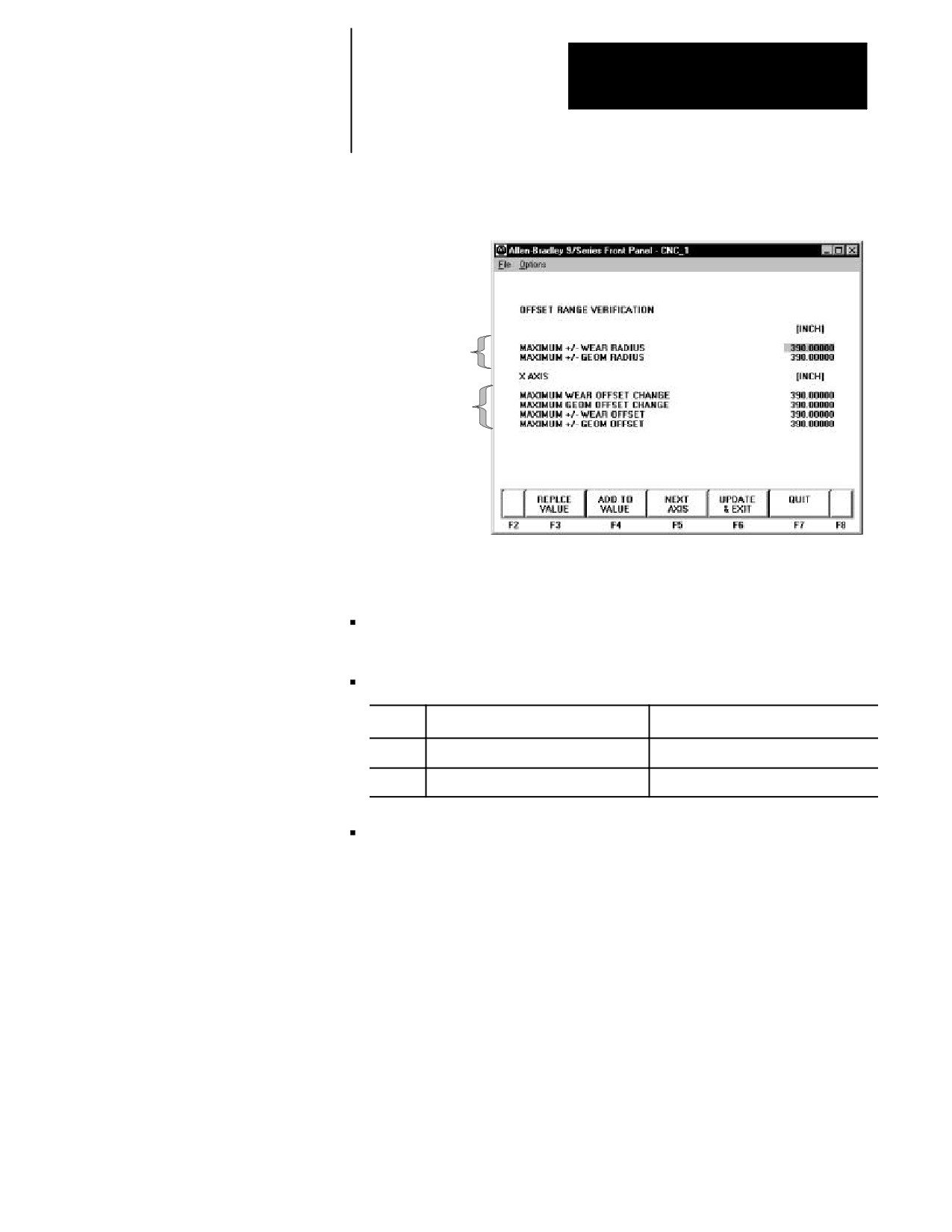
Your system installer initially sets these values in AMP. You can modify
them with online AMP by using this screen:
Per table values
Per axis values
softkey level 5
About the Offset Range Verification Screen
on a lathe, range checking units for this screen are always RADIUS,
regardless of the program/control mode
display format is fixed
Mode
Places to the left of the decimal point
Places to the right of the decimal point
inch
3
5
metric
4
5
data entry is bounded by the programming resolution of the axes
When Does Verification Occur?
Verification occurs when a value enters the table from:
· data entry screens
· PAL
· paramacros
Important: The control does not perform the verification if the value,
old or new, is zero, nor does it check G10 data-setting
codes.
3-13
Chapter 3
Offset Tables and Setup
Verify for Maximum Value
This value represents the absolute maximum value per table for all tool
offsets in that table.
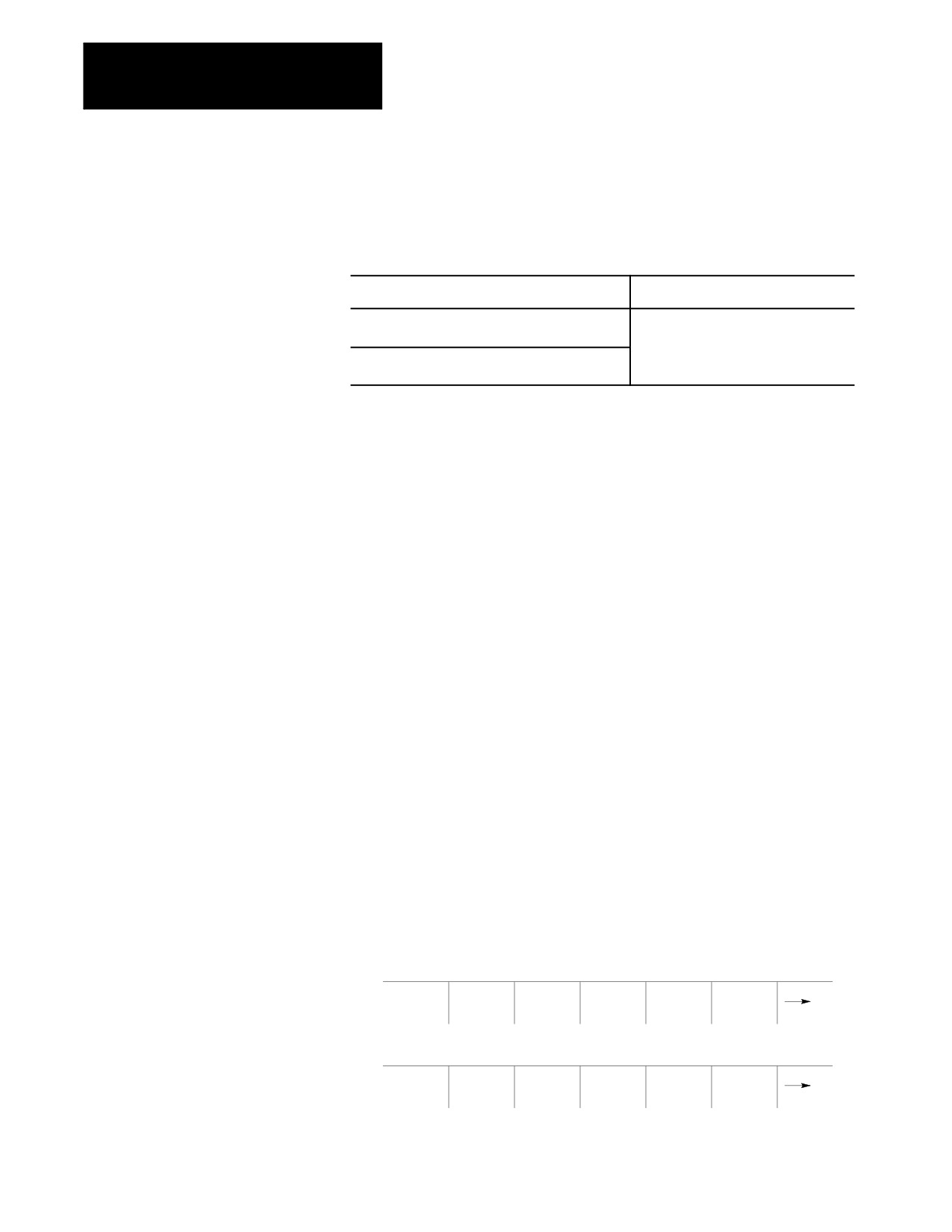
If you enter:
then:
a positive number greater than the maximum value
the control generates the error message:
“OFFSET EXCEEDS MAX VALUE”
a negative number less than the negative of the
The control does not modify the value in
maximum value
the table.
Verify for Maximum Change
This change represents the amount an offset may change from its current
value. If you exceed the amount set by the system installer in AMP, the
change is not allowed. The control generates the error message “OFFSET
EXCEEDS MAX CHANGE.”
3.2
Use {ACTIVE OFFSET} to allow the manual activation of tool offsets,
Changing the Active Tool
without the need to program the correct T-word to call the corresponding
offset number. This may be necessary when a broken tool has been
Offset {ACTIVE OFFSET}
replaced using the Jog Retract feature, or if a program is to start execution
with a tool active in the chuck and no tool offsets programmed, etc.
Typically tool offsets are changed by programming a T-word in a program
as described in chapter 20. This feature should be used only when it is
necessary to activate one of the tool offset numbers manually.
Important: The control must be in either cycle stop or E-Stop states
before an attempt is made to change the active offset using
this method.
If it is necessary to change the current tool offset values or to activate tool
offset numbers without programming a T-word, follow these steps:
1.
Press the {OFFSET} softkey.
(softkey level 1)
PRGRAM
OFFSET
MACRO
QUICK
SYSTEM
MANAGE
PARAM
CHECK
SUPORT
FRONT
ERROR
PASS-
SWITCH
PANEL
MESAGE
WORD
LANG
3-14
Chapter 3
Offset Table and Setup
2.
Activate an offset number as follows:
Press This softkey:
To activate:
the {TOOL GEOMET}
a tool geometry offset number
the {TOOL WEAR}
tool wear offset number
The tool offset table is displayed. Currently active offset values
(if any) are indicated with an * to the right of the offset number.
3.
Move the cursor on the offset table until the desired offset is shown in
reverse video. Only one geometry offset and one wear offset number
may be active at the same time.
4.
Press the {ACTIVE OFFSET} softkey when the desired offset is
selected. The tool offsets are made active as described in
chapter 20.
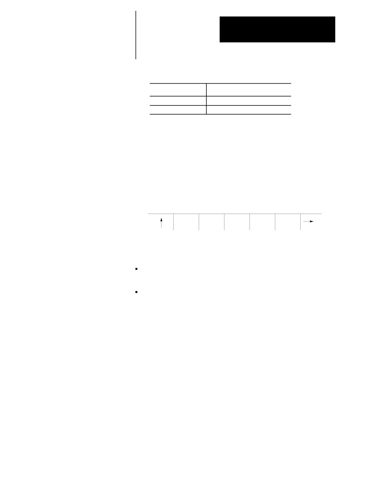
(softkey level 3)
SEARCH
REPLCE
ADD TO
ACTIVE
MORE
NUMBER
VALUE
VALUE
OFFSET
OFFSET
3.3
There are two types of data in the work coordinate system table. They are:
Work Coordinate System
the initial work coordinate system zero point locations that are called
Offset Table
when programming G54 - G59.3.
{WORK CO- ORD}
the external offset which is used to offset all of the G54 - G59.3 zero
points to make the same set of work coordinate systems fit a variety of
applications.
Zero Point Parameters
The zero point parameters refer to the zero point locations of all of the
work coordinate systems called out by G54 - G59.3. Enter positions for
these zero points as machine coordinate values. The control uses the
specified machine coordinate position as the work coordinate system zero
point. Refer to chapter 11 for details on work coordinate system.
Enter a machine coordinate system position for each axis of the work
coordinate system below the corresponding G-code (G54-G59.3) as
described on page 3-16.
3-15
Chapter 3
Offset Tables and Setup
External Offset
Use the external offset to modify all of the work coordinate system zero
points. Use of the external offset is optional. The value entered here
offsets all of the work coordinate systems by the specified amount. Enter
external offsets in the work coordinate system tables as the external offset
value.
This offset allows a programmer to use the same set of work coordinate
system values in a variety of applications. Adjusting this value, for
example, allows you to use the same work coordinate systems and
programs after a different part or tool mounting fixture has been installed
on the machine. You can also use it to offset all work coordinate systems
when part programs are transferred from different machines with different
mechanical features. Refer to chapter 11 for details on the external offset.
3.3.1
Set data in the control system table in one of these four ways:
Setting Work Coordinate
keying in the data directly into the table
System Data
programming G10s (chapter 11)
setting paramacro system variables (chapter 28)
entering data through the PAL program (refer to the 9/Series CNC PAL
Reference Manual)
When you use PAL to modify either the work coordinate system
tables or the tool offset tables, tool tip radius compensation should not
be active (G40 mode). If tool tip radius compensation is active, be
aware that the new offset is not placed in part program set-up buffers
that have already been read into control memory. This results in the
offset not being activated until several program blocks after the
current block. The number of setup buffers depends on the number of
block retrace steps configured in AMP and what software features are
currently being used.
To display or change the initial setups for the work coordinate system and
external offset, follow these steps:
1.
Press the {OFFSET} softkey on the main menu screen.
3-16
Chapter 3
Offset Table and Setup
(softkey level 1)
(softkey level 1)
PRGRAM
OFFSET
MACRO
QUICK
SYSTEM
MANAGE
PARAM
CHECK
SUPORT
FRONT
ERROR
PASS-
SWITCH
PANEL
MESAGE
WORD
LANG
2.
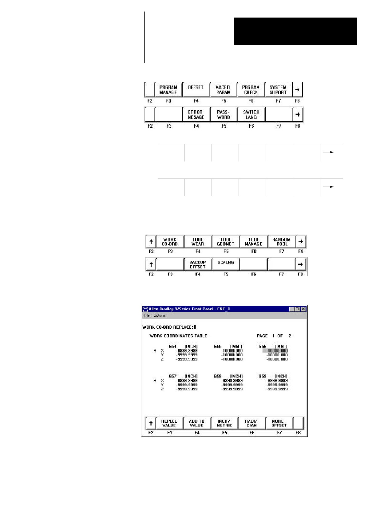
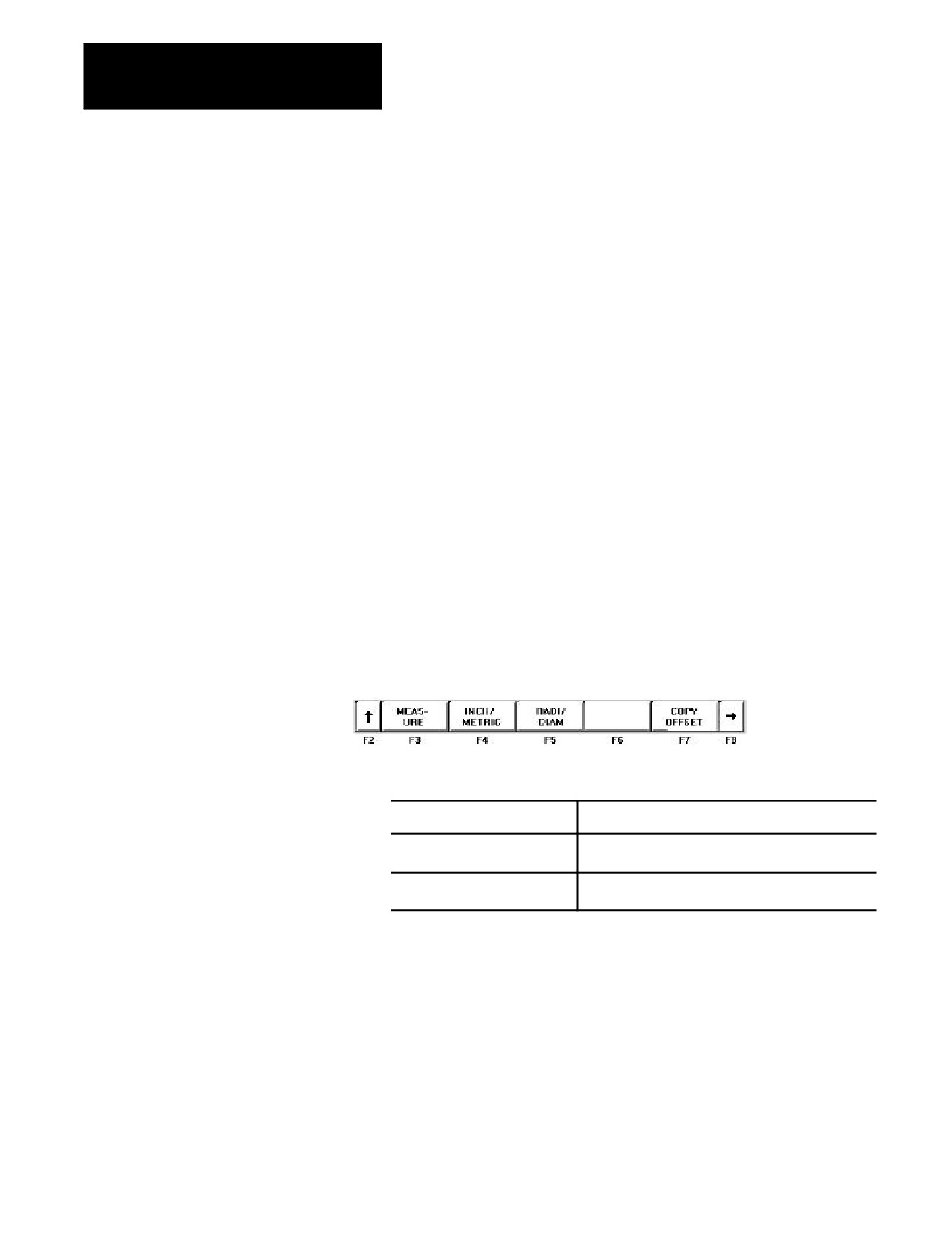
Press the {WORK CO-ORD} softkey to display the offset values for the
work coordinate systems and the external offset. See Figure 3.9.
(softkey level 2)
Figure 3.9
Work Coordinate System Setting
3.
Move the cursor to the offset data that you want to modify. Use the
up, down, left, or right cursor keys to move the block cursor to the
3-17
Chapter 3
Offset Tables and Setup
offset data on the current page. Press the {MORE OFFSET} softkey to
change pages. The selected item appears in reverse video.
4.
Select data entry type:
Unit selection {INCH/METRIC}
To select units of “mm” or “inch” for the offset data, press the
{INCH/METRIC} softkey. The units used for the currently selected
offset G-code or external offset change each time the softkey is
pressed. When the units are altered, all data previously entered is
converted to the newly selected units for that offset number.
Diameter or Radius {RADI/DIAM}
If the offset value being changed has been selected in AMP as the
diameter axis (typically the axis perpendicular to the spindle center
line), data may be entered into the offset table as either a radius or
diameter value. The current mode for this axis is displayed with an R
for radius or a D for diameter mode next to that axes offset. Pressing
the {RADI/ DIAM} softkey toggles the offset between these two
modes.
This softkey does not change the current mode of control operation
(as selected with G07 or G08); it only alters how data is entered into
the table. For details, refer to chapter 13 (G07/G08).
(softkey level 3)
5.
Replace or add data as follows:
To :
Press:
replace stored work coordinate
the {REPLCE VALUE} softkey, then type in the
data with new data
value and press [ENTER].
add to previously stored work
the {ADD TO VALUE} softkey, then type the
coordinate data
number and press [ENTER].
Important: The values for the work coordinate systems can be altered
by using the G10 command in MDI or within a part
program. For details, refer to chapter 11.
3-18
Chapter 3
Offset Table and Setup
3.4
The control can save all of the information that is entered in the tool offset
tables and the work coordinate system tables as a backup. This is
Backing Up Offset Tables
accomplished by the control generating a program consisting of G10
blocks. These G10 blocks contain the offset numbers and their respective
wear and geometry values. Any time your run this program, the set of
values contained in these G10 blocks replace the current values in the
offset tables. The G10 program can be saved in control memory.
This feature is very useful if the same tool or coordinate system offsets are
to be used on different machines. The same offset tables can be easily set
up by running this G10 program on other machines.
The offset table program can be saved in control memory as a program.
This is very useful if the same tools are to be used on different machines.
The offset tables can be easily set up by executing the same offset table
program on all the other machines.
Important: Once the control begins executing a G10 program that has
been previously generated, it clears any data that exists in
the offset table being updated by that G10 command. This
makes it impossible for a G10 block to simply add a few
offset values. A G10 program must load the entire offset
table each time it is run. Tool geometry and tool wear
tables are separate offset tables. Loading data into one does
not clear the other.
To back up the offset tables, follow these directions:
1.
Press the {OFFSET} softkey.
(softkey level 1)
2.
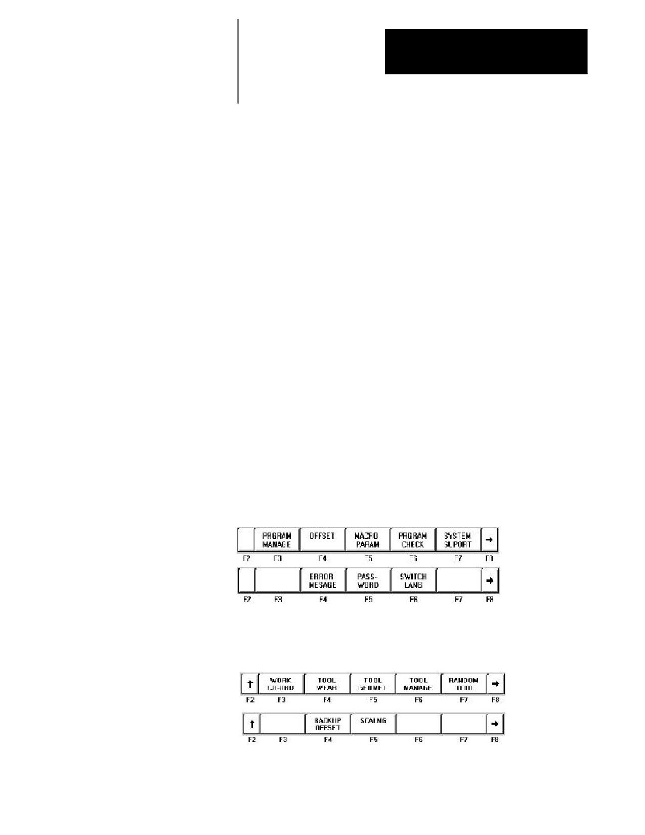
Press the {BACKUP OFFSET} softkey. The control displays the backup
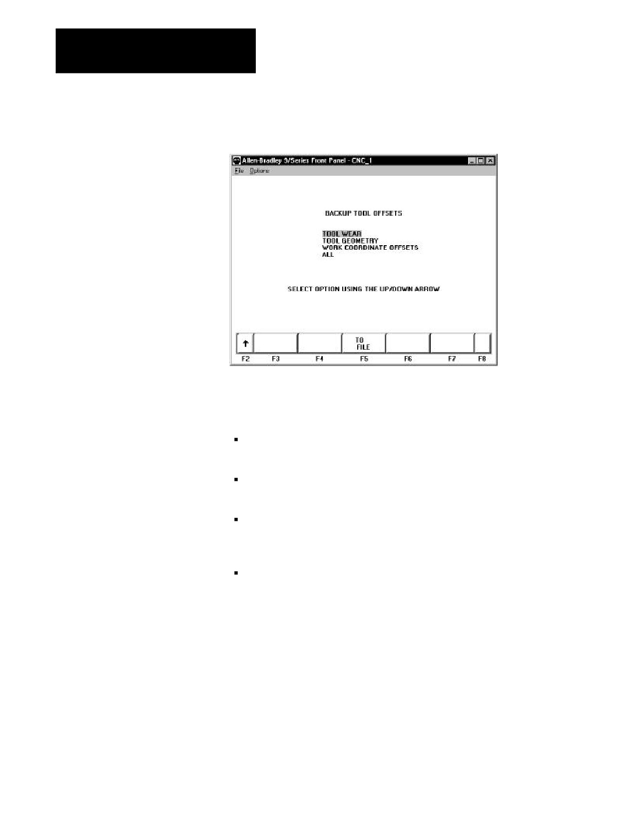
offset screen shown in Figure 3.10.
(softkey level 2)
3-19
Chapter 3
Offset Tables and Setup
Figure 3.10
Backup Offset Screen
3.
Select the offsets to be backed up by moving the cursor to the desired
offset by using the up and down cursor keys. The selected offset
appears in reverse video. The four options include:
TOOL WEAR ---- When wear is selected all data from the tool offset
wear tables is stored as a G10 program.
TOOL GEOMETRY ---- When geometry is selected all data from the
tool offset geometry tables is stored as a G10 program.
WORK COORDINATE ---- When work coordinate systems are selected
the work coordinate offset information for the G-codes G54 - G59.3 and
the external offset value are stored as a G10 program.
ALL ---- When all is selected all data from the tool offset geometry and
wear tables and work coordinate offset tables is stored as a G10
program.
4.
Once the data to save has been selected, press the {TO FILE} softkey
to send the G10 program to control memory. The control asks for a
program name under which to store the program. Enter the program
name by using the alphanumeric keys on the operator panel and press
the [ENTER] key. Refer to chapter 10 on program names. The G10
program is saved under the file name just entered.
3-20
Chapter 3
Offset Table and Setup
3.5
The programmable zone feature prevents tool motion from entering or
exiting a designated area. For details on programmable zones, refer to
Programmable Zone Table
chapter 12.
This table contains the values for programmable zones 2 and 3. These
values define the boundaries for the programmable zones and are
referenced from the machine coordinate system.
Important: These values may also be entered in AMP by the system
installer. Programmable zone 3 table values may also be
modified by programming a G22 command. Refer to
chapter 12.
To display or alter the values in the programmable zone table, follow these
steps:
1.
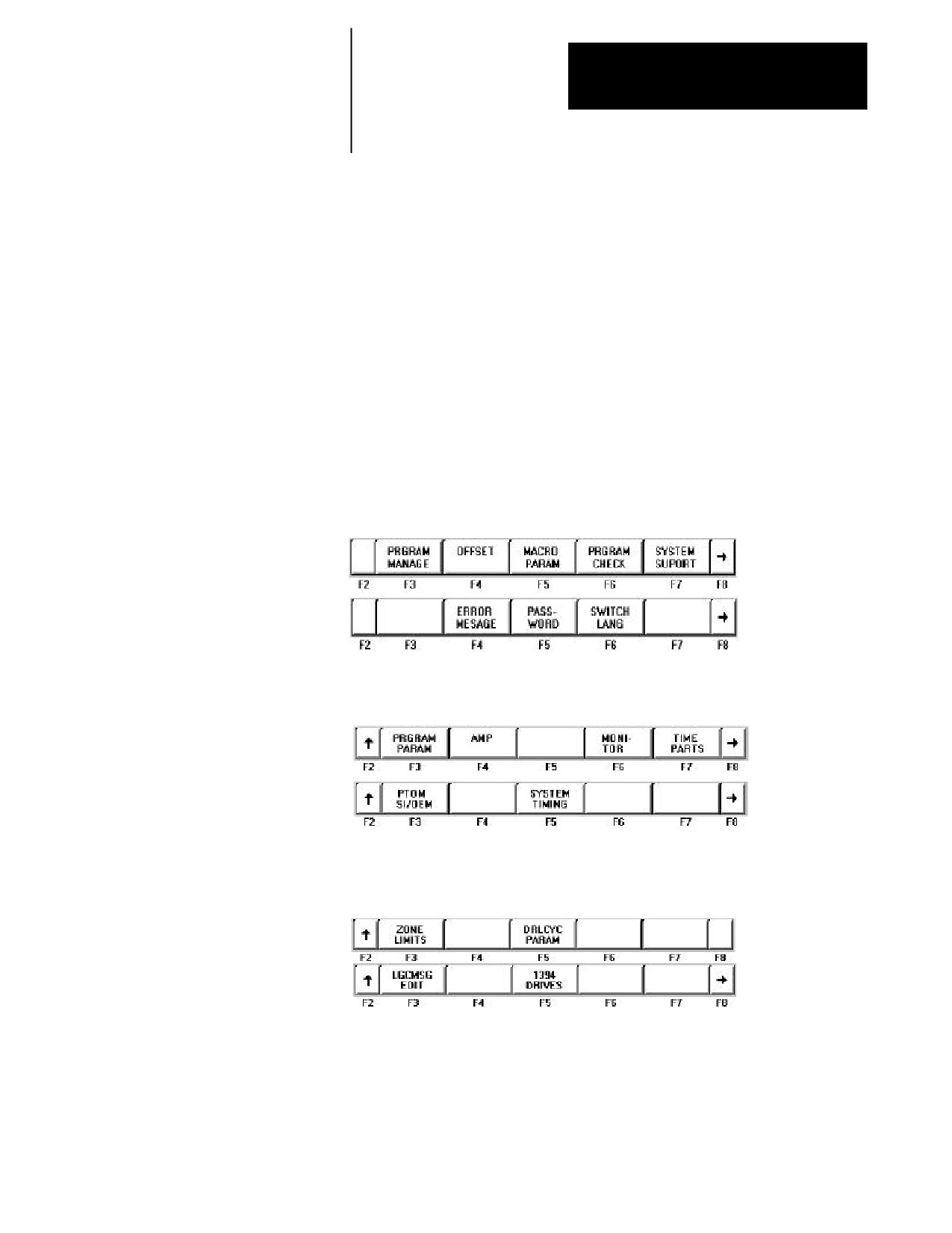
Press the {SYSTEM SUPORT} softkey.
(softkey level 1)
2.
Press the {PROGRAM PARAM} softkey.
(softkey level 2)
3.
Press the {ZONE LIMITS} softkey to display the programmable zone
table as shown in Figure 3.11.
(softkey level 3)
3-21
Chapter 3
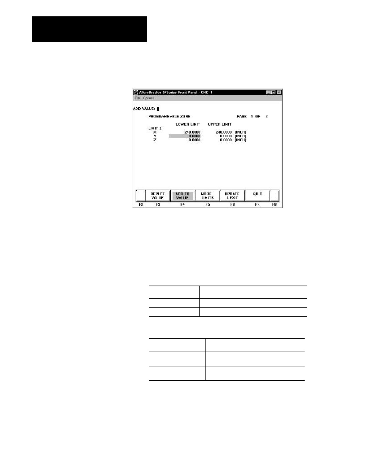
Offset Tables and Setup
Figure 3.11
Programmable Zone Table
Important: Depending on the currently active program mode,
programmable zone coordinates are displayed in inches or
millimeters for a liner axis and in degrees for a rotary axis.
4.
Use the up or down cursor keys to move the block cursor to the data
to be changed. Data located at the cursor appears in reverse video.
Press the {MORE LIMITS} softkey to change pages.
5.
You can replace data or add to it.
Press This Softkey:
Then:
{REPLCE VALUE}
type in the new value. Press [ENTER].
{ADD TO VALUE}
type in the new number. Press [ENTER].
6.
Complete editing the inhibit zone parameters in two ways:
Press This Softkey:
To:
{UPDATE & EXIT}
store the changes made to the parameters and
leave the inhibit zone screen.
{QUIT}
delete all changes made to the inhibit zones
this session and leave the inhibit zone screen.
3-22