9/Series CNC Lathe. Operation and Programming Manual - page 9
Chapter 8
Displays and Graphics
7.
Set the Main Program Sequence Starting #: parameter. It is only
available with QuickCheck. Use the up and down cursors to select
this parameter. Set it by typing in the new value for that parameter
using the keys on the operator panel. Press the [TRANSMIT] key when
the new value has been typed in. The old value for the sequence
number is replaced with the new value.
Use this parameter to select a sequence number (within a main
program) to mark where the graphics will begin drawing. Enter a
sequence number that is in the main program or zero as a value for
this parameter. The control does not search subprograms for
sequence numbers, so the sequence number entered here must be in
the main program, unless you enter a value of zero.
Graphics start drawing when the control begins executing the block
that corresponds to the entered sequence number. Entering a zero as
a sequence number causes graphics to begin executing the first block.
Entering any sequence number not found in the main program (other
than zero) stops the graphics from starting.
8.
Set the Main Program Sequence Stopping #: parameter. It is only
available with QuickCheck. Use the up and down cursors to select
this parameter. Set it by typing in the new value for that parameter
using the keys on the operator panel. Press the [TRANSMIT] key when
the new value has been typed in. The old value for the sequence
number is replaced with the new value.
Use this parameter to select a sequence number within a main
program for the graphics to stop drawing. Enter a sequence number
that is in the main program as a value for this parameter or enter a
value of zero. The control does not search subprograms for sequence
numbers, so the sequence number entered here must be in the main
program unless entering a value of zero.
Graphics stop drawing when the control finishes execution of the
block that corresponds to the entered sequence number. Entering a
value of zero (or any other sequence number not found in the main
program) causes the graphics to continue until the last block in the
main program is finished executing.
8-31
Chapter 8
Displays and Graphics
9.
Set the Process Speed parameter. It is only available with
QuickCheck. Use the up and down cursors to select this parameter.
Set it by pressing the left or right cursor keys. The data for the
selected parameter changes each time you press the left or right
cursor key.
Use this parameter to select the speed for the control to draw
graphics. There are two options available for process speed:
Choosing:
Causes the QucikCheck with graphics to be drawn:
FAST
at the full processor speed.
SLOW
to be drawn at a slower speed. This makes it easier to
determine the actual sequence of motion along the tool paths.
10.
Set Auto Erase. It is only available with active graphics. Use the up
and down cursors to select the parameter. Set it by pressing the left
or right cursor keys. The data for the selected parameter changes
each time you press the left or right cursor key.
Use this parameter when a part program is going to be executed many
times in repetition (as in production), and when you want a clear
graphics screen for displaying the part at the beginning of each part
program.
When you select :
The control:
YES
clears the graphics screen at the beginning of each program
execution.
NO
does not clear the graphics screen and any subsequent program
executions result in the graphics screen plotting the new tool paths
over the old tool paths on the screen.
Important: If you choose yes for this parameter and the first moves
in a part program are rapid, it is possible that the screen may not
clear before the beginning of the move. If this is the case, then a
small portion of the actual tool rapid motion is not displayed after the
screen clears.
11.
If you want to save these parameters, press the {SAVE PARAM}
softkey.
8-32
Chapter 8
Displays and Graphics
8.4.5
The active and QuickCheck graphics features can run in single-block or
continuous mode as described in chapter 8.
Graphics in Single-Block
In:
This happens:
Single block
one block of a part program executes each time you press the
<CYCLE START>.
Continuous mode
the control continues to execute blocks sequentially as they are read.
To control the speed of the graphics plot in QuickCheck, see
QuickCheck with graphic parameter “PROCESS SPEED”in chapter 1.
8.4.6
You can clear the screen if it becomes too cluttered because of many
different tool paths. Clear the currently drawn tool paths by pressing the
Clearing Graphics Screen
{CLEAR GRAPHS} softkey. Any tool paths on the screen are erased and the
plot continues from the current tool location without stopping.
You can clear active graphics with Auto Erase. Refer to page 8-32.
8.4.7
The machine information window displays the currently programmed axes
positions, feedrate, active tool number, and active work coordinate system
Displaying Machine
G-code along with G52, if there is a G52 offset active.
Information in Graphics
Press the {MACHNE INFO} softkey to activate the machine information
window. The window toggles on and off each time you press the softkey.
Move the machine information window around the screen to prevent it
from obscuring any tool paths. Press the up, down, right, and left cursor
keys on the operator panel.
8.4.8
You can take a closer look at a specified area of tool motion on the graphic
display. This is helpful when you want to get a better view of the actual
Zooming Graphics
tool paths in that area or if the part being machined is too small to be easily
seen on the current graphic display. Press the {ZOOM WINDOW} softkey to
display the zoom window graphic display screen.
8-33
Chapter 8
Displays and Graphics
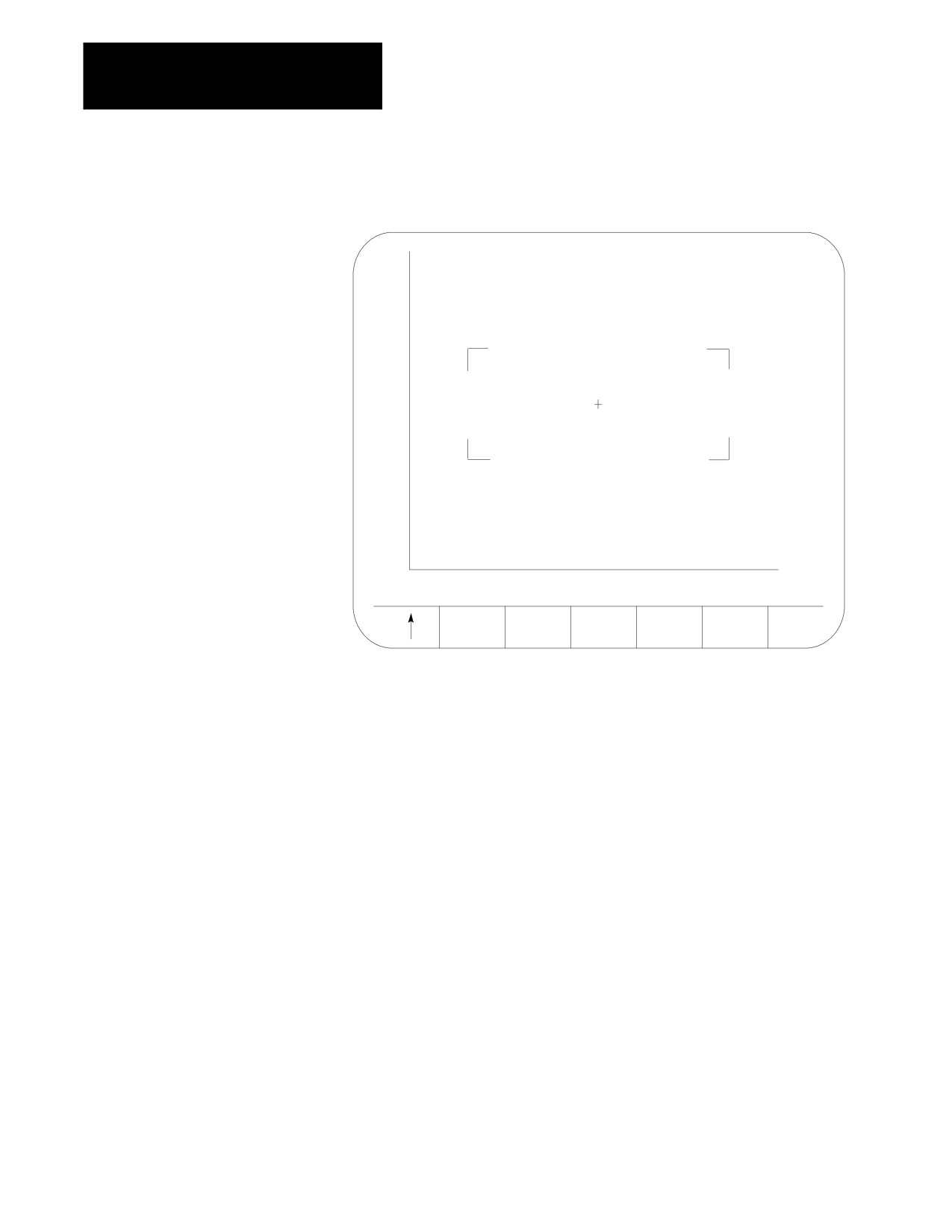
Figure 8.19
Zoom Window Graphic Display Screen.
20.0
15.6
11.1
6.7
2.2
-2.2
-6.7
X
-11.1
-15.6
-20.0
-20.0
-10.3
Z -0.5
9.2
18.9
27.7
38.4
48.1
57.9
INCR
DECR
ZOOM
ZOOM
WINDOW
WINDOW
ABORT
This screen resembles the regular QuickCheck graphics screen with the
exception that it includes a window and different softkeys. Use the
window to define a new size and location for the tool path graphic display.
The area within the window will become your next screen. The crossed
lines (+) become the center of the screen. You must move the window to
the location that you want to zoom in on to make sure that it appears on
your next screen. It is helpful to run the program first so that you can see
the tool path. This helps you position the tool path within the window.
If you decide not to change the window size or location, press the
{ZOOM ABORT} softkey to abort the operation and return to the graphics
screen.
Important: Any time you change the window size and/or location, the
control erases all tool paths from the screen. These tool paths cannot be
recovered. When returning to the graphics screen using a new window, the
graphics plot starts from the current tool position.
8-34
Chapter 8
Displays and Graphics
To use the zoom window feature:
1.
Press the {ZOOM WINDOW} softkey. This changes the display to the
zoom window display.
(softkey level 3)
CLEAR
MACHNE
ZOOM
ZOOM
GRAPH
GRAPHS
INFO
WINDOW
BACK
SETUP
2.
Use the cursor keys on the operator panel to move the center of the
window around the screen. To move the window center at a faster
rate, press and hold the [SHIFT] key while pressing the cursor keys.
Important: On this screen, the machine information window cannot be
moved. The cursor keys are dedicated to the zoom window only.
If more than one window is displayed (as in the case of 3 axis
graphs), choose the window to move by pressing either the
{SELECT UPPER} or {SELECT LOWER} softkey. This softkey toggles
between upper and lower each time that you press it. If both the
upper and lower graph have a common horizontal axis, the left and
right cursor keys move both windows. The current window that is
the active moveable window for the 3-axes graph is displayed with a
+ symbol in the center of the window.
(softkey level 4)
INCR
DECR
ZOOM
ZOOM
SELECT
WINDOWWINDOW
ABORT
UPPER
or
SELECT
LOWER
Important: The {SELECT UPPER} or {SELECT LOWER} softkey is only
displayed if the control is currently using a 3-axes display for the graphics
screen.
If the center of the window is moved up against the boarder of the
displayed axis, the window size shrinks automatically. This keeps
the window within the active area of the tool paths. Otherwise, the
zoom window is displayed at a default size and the cursor keys only
move the window center.
8-35
Chapter 8
Displays and Graphics
3.
To change the size of the window, use the {INCR WINDOW} or
{DECR WINDOW} softkeys. To change the window size at a faster rate,
press and hold the [SHIFT] key while pressing the {INCR WINDOW} or
{DECR WINDOW} softkeys.
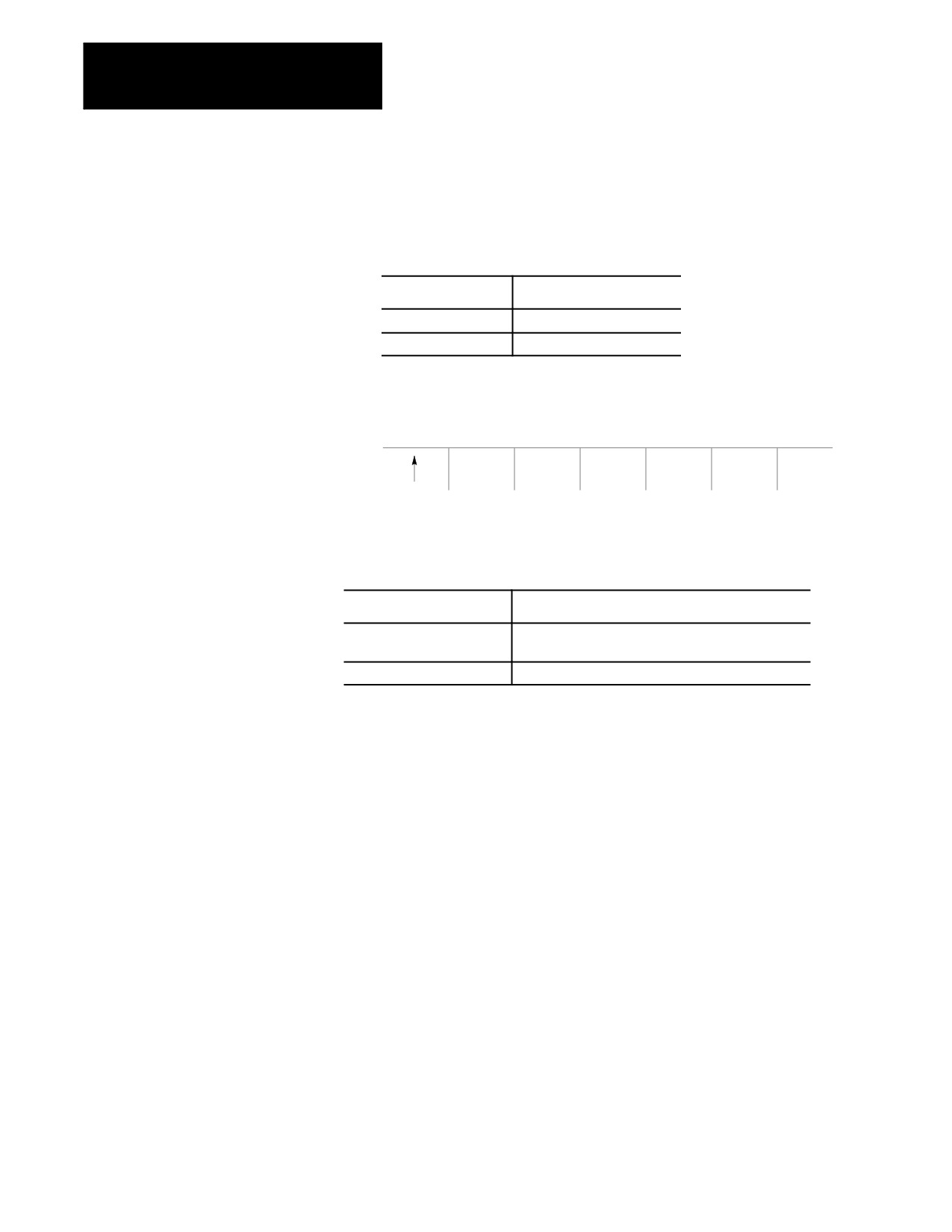
Each time you press:
The Zoom Window :
{INCR WINDOW}
increases in size.
{DECR WINDOW}
decreases in size.
4.
Once the size and the location of the window are correct, press the
{ZOOM} softkey to return to the regular QuickCheck graphics screen.
(softkey level 4)
INCR
DECR
ZOOM
ZOOM
WINDOW
WINDOW
ABORT
The graphics screen is automatically cleared of the previously plotted tool
paths. The control begins plotting new tool paths from its current location
in the program using the new window size.
If you press {ZOOM BACK}:
It:
one, two or three times
reverses the zoom in increments, going back to your
most recent zoom (not the original).
a fourth time
returns the graphics screen to the default size.
When you press the {ZOOM BACK} softkey, the control clears the graphics
screen of any previously plotted tool paths. The control resumes plotting
new tool paths from its current location in the program using the current
window size.
8-36

Chapter 8
Displays and Graphics
8.5
When power is turned on, the control displays the power turn-on screen .
Power Turn-on Screen
The following section discusses how to modify information displayed on
this screen at power up.
Editing the System Integrator Message Lines
To edit the system integrator message lines of the power turn-on screen, do
the following:
1.
Press the [SYSTEM SUPORT] softkey.
(softkey level 1)
PRGRAM
OFFSET
MACRO
QUICK
SYSTEM
MANAGE
PARAM
CHECK
SUPORT
FRONT
ERROR
PASS-
SWITCH
PANEL
MESAGE
WORD
LANG
The control brings you to softkey level 2.
2.
Press the [PTOM SI/OEM] softkey.
(softkey level 2)
PRGRAM
AMP
DEVICEMONI-
TIME
PARAM
SETUP
TOR
PARTS
PTOM
SYSTEM
SI/OEM
TIMING
The control changes the screen to display the PTO screen, as shown in
section 8.6.
* Asterisks indicate the three lines for system integrator messages. The
softkeys used to change these lines are password protected.
3.
Use the up or down cursor keys to highlight the line that you want to
change on the PTO screen. The line selected is shown in reverse
video.
8-37
Chapter 8
Displays and Graphics
4.
Press the {ENTER MESAGE} softkey. This highlights the softkey, and
the control displays the input prompt “PTO MESSAGE:” at the top of
the screen. Also, the current text, if any, of the selected message line
is shown on the input line next to the prompt. (The text may be
edited like any other input string.)
(softkey level 3)
ENTER
STORE
MESAGE
BACKUP
5.
Once the line has been edited, press the <TRANSMIT> key. This
transfers the edited line to the PTO screen. After pressing the
<TRANSMIT> key, you can either:
edit another line
exit the PTO screen by pressing the up arrow softkey
6.
To save changes to the system integrator message lines, press the
{STORE BACKUP} softkey. When pressed, the softkey will be shown
in reverse video until the control has finished storing the lines.
Important: If the messages are not stored to EEPROM, the text will be
lost the next time the system is powered down.
(softkey level 3)
ENTER
STORE
MESAGE
BACKUP
8.6
The 9/Series screen saver utility is designed to reduce the damage done to
the CRT from “burn in”. Burn in is the result of the same lines or
Screen Saver
characters being displayed at the same location on the screen for a such a
long period of time that they leave a permanent imprint on the CRT.
After a preset length of time without any keyboard strokes, the screen
saver utility replaces the 9/Series display with a single horizontal line that
continuously scrolls from top to bottom on the CRT. This horizontal line is
a standard character high, green on color operator panels, amber on
monochrome.
When any operator panel key, PAL keyboard request, or softkey is pressed,
the display is returned to the last viewed 9/Series display. Exceptions are
screens accessed through hot keys on the keyboard (such as Display Select
or the PAL rung monitor). When the screen saver returns from one of
these screens, the 9/Series screen previous to the hot key selection is
displayed.
8-38

Chapter 8
Displays and Graphics
In the event that a system error or warning, PAL display page, PAL
message, or E-Stop condition occurs while the screen saver is active, the
horizontal scrolling line is replaced with a scrolling message “MESSAGE
PENDING, PRESS A KEY TO DISPLAY.” The operator should press any
keyboard key or softkey to return to the normal 9/Series screen and view
the condition. The system installer can write PAL to disable the screen
saver automatically when one of these conditions occur.
Important: The system installer has the ability to disable the softkey
activation of the screen saver utility in the PAL program. Refer to your
system installer’s documentation for details.
The screen saver does not impact machine operation. MTB panel, PAL, or
part program requests for machine motions or functions occur regardless of
the status of the CRT. You should exit the screen saver before performing
manual or PAL machine motions. It is also recommended you disable the
screen saver for the first few runs of a part program until you are confident
machine motions are occurring as desired.
Enable the screen saver and set the activation timer value (time without
any keyboard input before the screen saver starts) as follows:
1.
Press the [SYSTEM SUPORT] softkey.
(softkey level 1)
PRGRAM
OFFSET
MACRO
QUICK
SYSTEM
MANAGE
PARAM
CHECK
SUPORT
2.
Press the [SCREEN SAVER] softkey.
(softkey level 2)
PRGRAM
AMP
DEVICEMONI-
TIME
PARAM
SETUP
TOR
PARTS
PTOM
SYSTEMSCREEN
SI/OEM
TIMING
SAVER
8-39
Chapter 8
Displays and Graphics
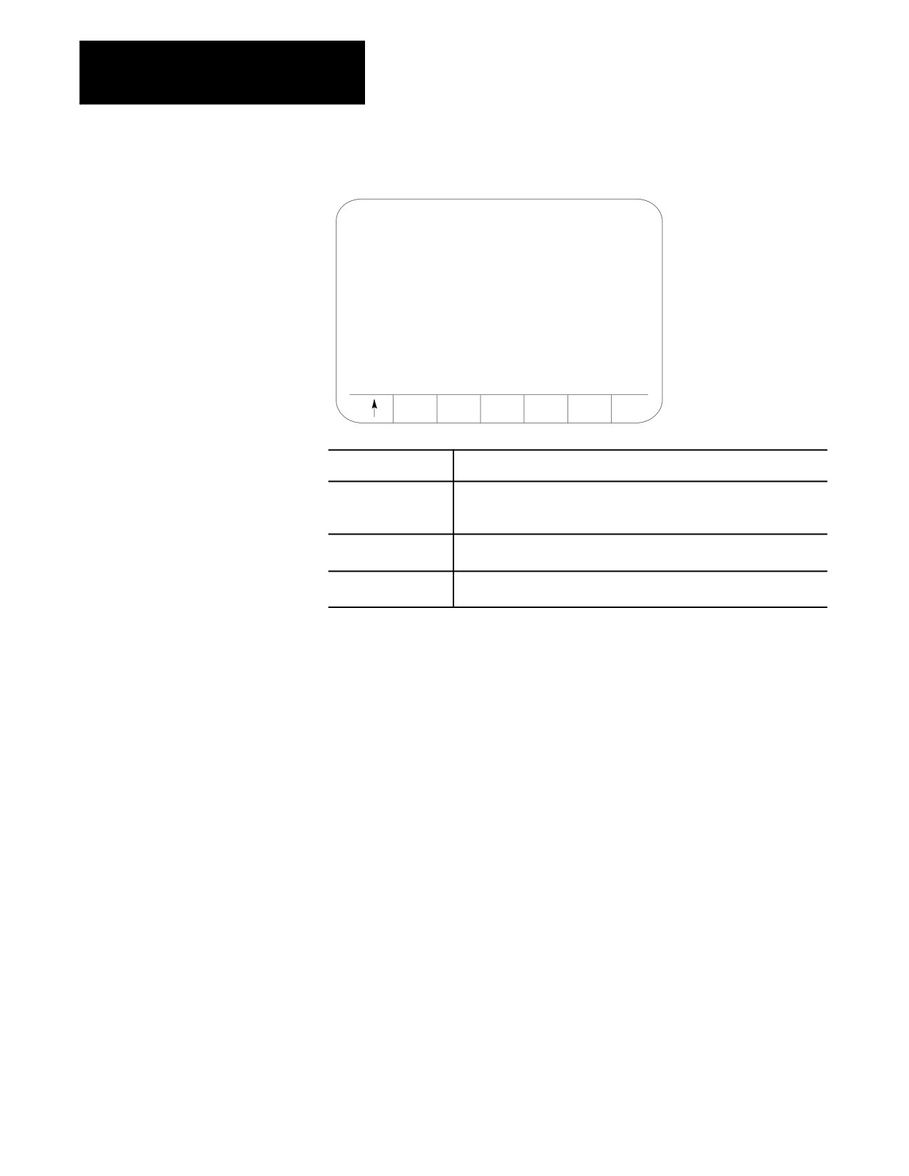
The screen saver setup screen appears.
SCREEN SAVER
ACTIVATION TIMER : 05 MINUTES
SAVER
INCR
DECR
ON/OFF
TIMER
TIMER
Press This Softkey
To:
SAVER ON/OFF
toggle between enabling and disabling the screen saver. When the
softkey name is shown in reverse video, the screen saver is enabled.
Note the system installers PAL program can override this softkey setting.
INCR TIMER
increase the duration of the Activation Timer by five minute increments.
The activation timer can be set to a maximum of 60 minutes.
DECR TIMER
decrease the duration of the Activation Timer by five minute increments.
The activation timer can be set to a maximum of 60 minutes.
The activation timer determines the length of time that takes place after the
last keyboard or softkey stroke occurred before the screen saver starts.
Softkey settings that activate the screen saver and determine the activation
timer duration remain active even after power is cycled.
END OF CHAPTER
8-40
Chapter
9
Communications
9.0
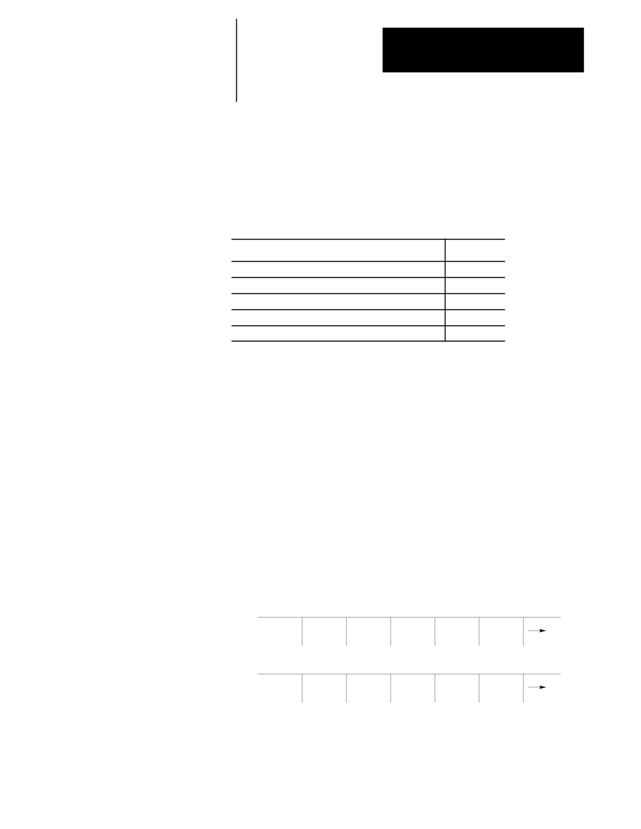
This chapter covers:
Chapter Overview
Topic
On page:
Communication port parameters
9-3
Inputting part programs from a tape reader
9-9
Outputting part programs to a tape punch
9-13
Verifying saved materials
9-17
Error conditions for inputting and outputting part programs
9-18
9.1
This section covers the communication port parameters that are available
with the control. You use communication parameters to let the control
Setting Communications
communicate with peripheral devices.
The control has default parameters permanently stored in memory for a
number of peripheral devices. These devices are listed in Table 9.A and
are selected by the DEVICE parameter. You can also modify the default
parameter separately for each device.
9.1.1
This section explains how to change communication parameter values. A
description of each of the parameters is presented on page 9-3.
Setting Communication Port
Parameter Values
Display the device setup screen as follows:
1.
Press the {SYSTEM SUPORT} softkey.
(softkey level 1)
PRGRAM
OFFSET
MACRO
QUICK
SYSTEM
MANAGE
PARAM
CHECK
SUPORT
FRONT
ERROR
PASS-
SWITCH
PANEL
MESAGE
WORD
LANG
9-1
Chapter 9
Communications
2.
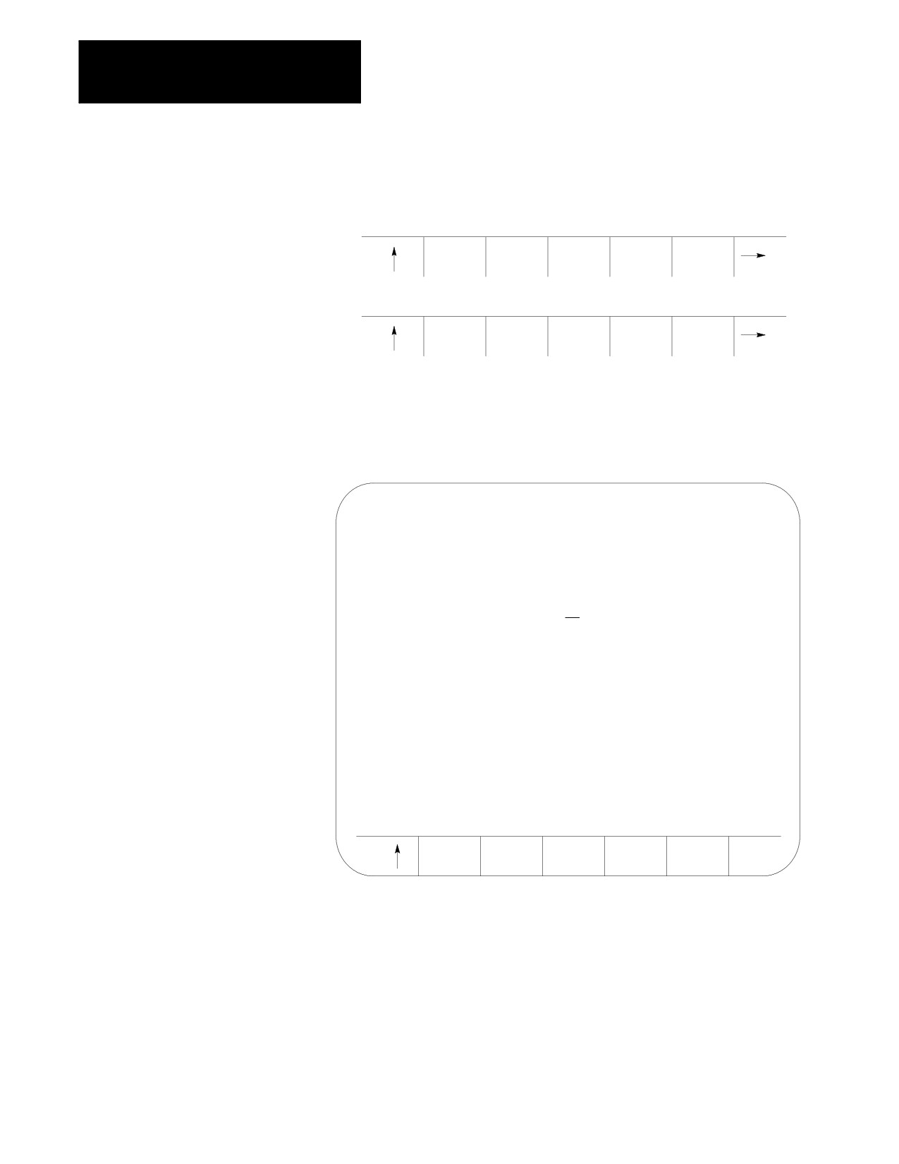
Press the {DEVICE SETUP} softkey to display the device setup screen
as shown in Figure 9.1.
(softkey level 2)
PRGRAM
AMP
DEVICE
MONI-
TIME
PARAM
SETUP
TOR
PARTS
PTOM
SI/OEM
The 9/230 CNC does not support port A. It uses only port B.
Figure 9.1
Device Setup Screen
E-STOP
SERIAL PORT:
A
DEVICE:
DECITEK AB 8000-XPDR
PORT TYPE:
RS232C
BAUD RATE:
1200
PROTOCOL:
LEVEL
2*
PARITY:
EVEN
STOP BITS:
1
DATA LENGTH:
8
TIMEOUT:
15 SEC
OUTPUT CODE:
N/A
AUTO FILENAME: NO
STOP PRG END: YES
PROGRAM END:
M02, M30:
YES
M99:
YES
%:
NO
PRGRM NAME:
YES
SAVE
COPY
CHANGE
DEFLTS
Important: Figure 9.1 displays a typical tape device setup screen. AUTO
FILENAME, STOP PRG END, and PROGRAM END are available only if
you have selected a tape reader or tape punch as your device. Refer to
page 9-4 on selecting a device.
9-2
Chapter 9
Communications
3.
Use the up or down cursor keys to move the cursor to the parameter
to be changed. The current value for each parameter will be shown in
reverse video.
Important: Select both the SERIAL PORT (A or B) and the DEVICE
being set first (see Figure 9.1) since all other parameters are device
dependent.
4.
To change a value after a parameter has been selected, press the left
or right cursor keys. The control scrolls through the available
parameter values as the left or right cursor key is pressed (or held).
5.
To save the changes made to the communications parameters for a
specific peripheral device, press the {SAVE CHANGE} softkey. The
message “SAVE COMPLETED” is displayed. If the saved
parameters differ from the default parameters for that device, the
message “PARAMETERS DO NOT MATCH THE DEFAULTS”
appears beneath the parameters.
Important: You must save changes made to the parameter values for a
peripheral device before you select another device.
To restore the default parameters for a particular device, select that device
using the left or right cursor key, and press the {COPY DEFLTS} softkey.
The message “DEFAULTS LOADED” appears at the top of the screen.
To exit the device setup screen, press the exit {} softkey.
Important: When you exit, the serial ports and devices displayed on the
device setup screen becomes your current settings.
9.1.2
PORT (setting of input/output port)
Communication Port
The 9/240, 9/260, 9/290 and 9/440 controls have two communication
Parameters
ports: A and B. The 9/230 control uses only port B. This parameter
selects which of the two ports is going to be modified.
When you select:
This letter
displays:
port A
A
port B
B
9-3

Chapter 9
Communications
All of the following parameters can be set independently for each
communication port (A or B).
DEVICE (setting type of peripheral)
Select your peripheral device immediately after selecting your serial port.
The devices with default communication parameters stored in the control
are listed in Table 9.A. If the device that you are using is not listed, select
either USER PUNCH, USER PRINTER, or USER READER.
Important: You cannot select the same device for both peripheral ports.
Once you select a device for PORT A, that device is no longer an option
available for PORT B and vice-versa.
Table 9.A
Available Devices For Communication
Device
Device Type
Allen-Bradley 1770-SB
Cartridge
Ricoh PTR240R
Facit N4000
Reader
Decitek AB 8000-XPDR
DSI SP75
Facit 4070
Punch
Facit N4000
Epson LX-810 (USA)
Printer
Epson SP-500 (JAPAN)
User Punch
User Reader
User Defined
User Printer
Teach Pendant
PAL-RS232 Comm
ODS
ODS Terminal
Generic Level_2
Computer using only level 2 protocol
Greco Minifile
Intelligent Storage
Intelligent Device
Personal Computer using
Communication Software
For more information on some of these peripheral devices and their
function, refer to your 9/Series CNC Integration and Maintenance
Manual.
9-4
Chapter 9
Communications
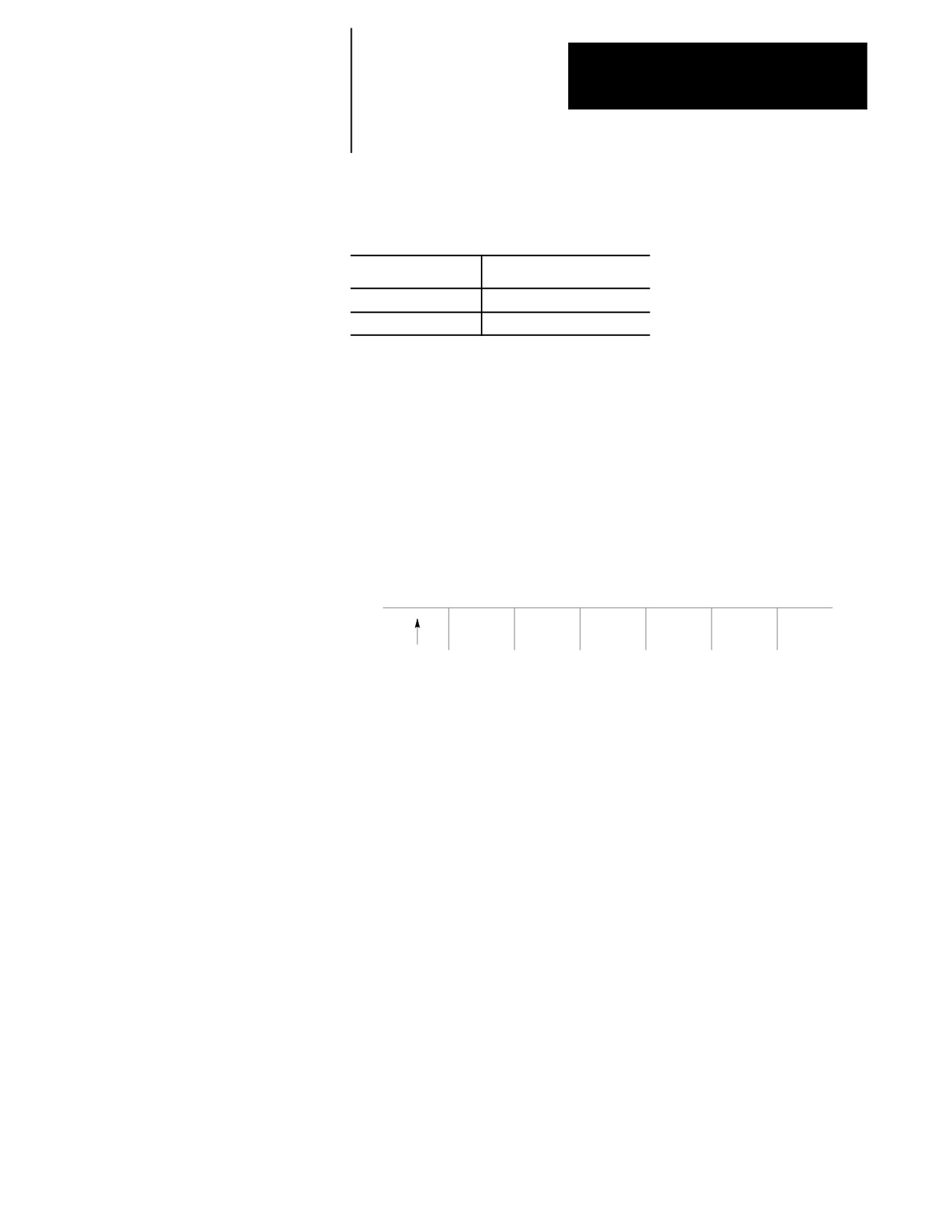
PORT TYPE
Port type options differ depending on the port you select.
Port
Type
Port A
RS232-C
Port B
RS232-C or RS422A
BAUD RATE
You can set the baud rate at these speeds (in bits per second):
300, 600, 1200, 2400, 4800, 9600, MAX
MAXIMUM BAUD RATE
If you need to operate your 9/Series control at a baud rate higher than
9600 bps, you can toggle between 19200 (default setting) and 38400 bps:
SAVE
COPY
SETMAX
SETMAX
CHANGE
DEFLTS
19200
38400
Important: The “SAVE CHANGES” and “COPY DEFLTS” softkeys
have no affect on the maximum baud rate setting.
Although you can make your selection at any time, only when “MAX”
displays is it implemented for all ports on your control. Until then, your
selection is highlighted to remind you of your currently selected maximum
baud rate. Once you’ve made a selection, it is effective until you make
another selection.
Important: Selecting a maximum baud rate that your device does not
support causes the selection to be ignored. For ODS device drives, you
must cycle power on the control after changing the baud rate in order for
the control to recognize your selection. If one or both ports are busy, the
request to select a maximum baud rate is ignored, returning the error,
“PORT IS BUSY -- REQUEST DENIED”.
Important: Your “MAX” selection establishes the maximum baud rate for
all serial ports on your 9/Series control. A combination of 19200 baud on
one port and 38400 baud on another port is not allowed.
9-5
Chapter 9
Communications
PROTOCOL
Select the protocol for communications from the following options.
LEVEL_1
LEVEL_2*
DF1
RAW
PARITY (parity check)
Select the parity from the following parity check schemes:
Parity
Parity Check
NONE
No parity check
EVEN
Even parity
ODD
Odd parity
STOP BIT (number of stop bits)
Select the number of stop bits with this parameter. You can select:
1, 1.5, or 2 bits
DATA LENGTH
Select the number of bits that constitute one character with this parameter.
You can select:
7 or 8 bits
The parity bit is not counted as a data length bit.
TIME-OUT
Select the time-out value that specifies how long the control tries to
establish communications with a peripheral. If the control cannot establish
communications within the specified time-out value, an error message is
displayed on the control’s CRT. You can select:
3, 15, 30, or 60 seconds
or
2, 3, 5, or 10 minutes
or
UNLIMT (no time-out)
9-6

Chapter 9
Communications
OUTPUT CODE
Select either EIA (RS-244A) or ASCII (RS-358-B) as output codes for 8
bit data lengths. Selecting 7 bit data length sets this output code to “N/A”
since EIA and ASCII do not apply to this type.
AUTO FILENAME
This parameter is valid only if you are inputting part programs to the
control from a tape reader (refer to DEVICE for details). This parameter is
used only if your tape contains more than one part program.
AUTO FILENAME lets you either automatically assign program names to
all programs or key in or read the filenames for each program individually
as they are copied into memory from a multiple program tape.
Setting
Result
Yes
The first program on a multiple-program tape must have its program name either keyed in manually, or
there must be a program name as the first block of the first program. The control automatically creates
program names for successive programs on that tape by incrementing the program name by one as each
new program is read. Any program names that exist as the first block of the program are ignored for any
program read after the first program on tape (though these blocks are still copied into memory they are not
used as the program name). An error is generated if when reading program names into memory, the
control needs to increment a program name that is greater than 99999.
Important: If the first program name is to be read from tape (not manually keyed in), the first block of
the first program must contain a program name in one of the following formats: Oxxxxx (ASCII), Nxxxxx or
:xxxxx where xxxxx is any valid integer.
No
The program name for each program on a multi-program tape must be either entered from the keyboard or
located as the first block of each program after the program start code on the tape. If no program name is
found in the first block and no program name is keyed in, an error is generated.
Important: If the program name is to be read from tape (not manually keyed in), the first block of the
program must contain a program name in one of the following formats: Oxxxxx (ASCII), Nxxxxx or :xxxxx
where xxxxx is any valid integer.
9-7
Chapter 9
Communications
STOP PRG END
This parameter is available only if you are reading a tape and have selected
a tape reader as your device (refer to DEVICE for details). It determines if
the tape reader is to stop at the end of each program or continue reading
until the end-of-tape code is reached. Refer to the PROGRAM END
section to determine what defines the end-of-program for your system.
Setting
Result
Yes
the tape reader stops every time it encounters a program end code.
No
the tape reader stops only if it encounters an error condition or the end of tape code.
CAUTION: If no program end code is found while reading a multi-program
tape, all programs are read and merged into one program.
Important: If % is the program end code on your tape, the tape reader
stops every time it encounters a “%”. consequently, even if STOP PRG
END is set to “no”, the tape reader will stop at the end of each program.
The tape reader stops if % (ASCII) or ER (EIA) is found. If you selected
% as the program end-code with (ER) format, you can continue reading on
that tape after a % is read. However, if you selected M30, M02, or M99,
and one of these M-codes is read followed by a % (ER), the % is
considered the tape end, and the directory screen is displayed.
PROGRAM END
This parameter is available only if you select a tape reader or tape punch as
your device (refer to DEVICE for details). It is used to designate valid
“end-of-program”codes. You can select more than one of these codes at a
time.
The tape reader stops every time it encounters one of these program
end-codes that has been set to “yes” on the device setup screen. This
assumes that the STOP PRG END parameter has been set to “yes” (refer to
the STOP PRG END section). If STOP PRG END is set to “no”, the tape
reader does not stop unless % (ER) is encountered. Each program read is
stored in the control’s memory.
9-8

Chapter 9
Communications
If “%” is set to “yes”, making it a valid program end-code, no program
end-code other than PRGRM NAME can be set to “yes”. If another
program end-code is set to “yes”, the “%” option is automatically set to
“no”. Refer to the descriptions for M-codes in chapter 10 for details.
M02, M30 -- refer to the descriptions for M-codes in chapter 10 for
details
M99 -- refer to the descriptions for M-codes in chapter 10 for details
% -- also used as end-of-tape code. Refer to section on STOP PRG
END
Important: If you set the “%” field to “yes”, the tape punch adds a %
code after the last block of every program that is output to tape.
PRGRM NAME -- if set to “yes”, a program name is recognized as the
end of the previous program. The program name must be in one of
these forms where xxxxx indicates an integer from 0 to 99999:
Oxxxxx
(ASCII)
:xxxxx
(EIA)
Nxxxxx
(except for N00000)
Important: If an N-code is used to designate the program name, be aware
that all part program blocks that contain N-codes will be interpreted as new
part programs.
9.2
If a program is loaded on a peripheral device, such as a tape reader, and
you want to send a copy of that program to control memory, follow these
Inputting Part Programs
steps:
from a Tape Reader
1.
Verify that the peripheral device is connected to the correct serial port
and that the port is configured for that device (refer to page 9-1).
2.
Press the {PRGRAM MANAGE} softkey. Figure 9.2 displays the program
directory screen.
(softkey level 1)
PRGRAM
OFFSET
MACRO
QUICK
SYSTEM
MANAGE
PARAM
CHECK
SUPORT
FRONT
ERROR
PASS-
SWITCH
PANEL
MESAGE
WORD
LANG
9-9
Chapter 9
Communications
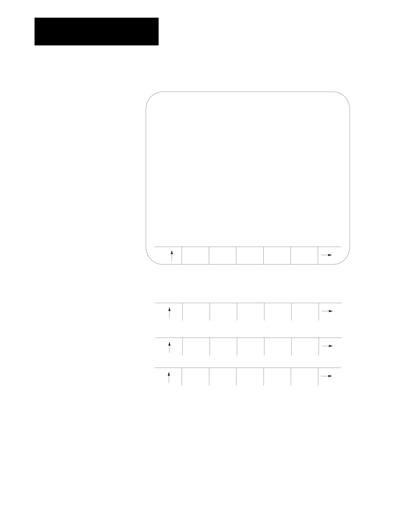
Figure 9.2
Program Directory Screen
SELECTED PROGRAM:
DIRECTORY
PAGE
1
OF
1
NAME
SIZE
COMMENT
O12345
1.3
SUB TEST 1
TEST
3.9
NEW
MAIN
1.3
TTTE
1.3
THIS IS A TEST PROGRAM
XXX
1.3
5 FILES
120.7
METERS FREE
ACTIVE
EDIT
RESTRT
DISPLY
COPY
PRGRAM
PRGRAM
PRGRAM
PRGRAM
PRGRAM
3.
Press the {COPY PRGRAM} softkey.
(softkey level 2)
ACTIVE
EDIT
RESTRT
DISPLY
COPY
PRGRAM
PRGRAM
PRGRAM
PRGRAM
PRGRAM
VERIFY
PRGRAM
DELETE
RENAME
INPUT
PRGRAM
COMENT
PRGRAM
PRGRAM
DEVICE
REFORM
MEMORY
4.
If the name is already entered in the program, skip step 4 and go to
step 5. Otherwise enter the program name to copy by either selecting
it using the up/down cursor keys or typing it in using the
alphanumeric keys on the keyboard. The program name is displayed
on the input line (line
2) of the screen next to the prompt
“FILENAME:”.
If an error is made while typing in the new program name,
corrections can be made on the input line as discussed on page 2-37.
9-10
Chapter 9
Communications
5.
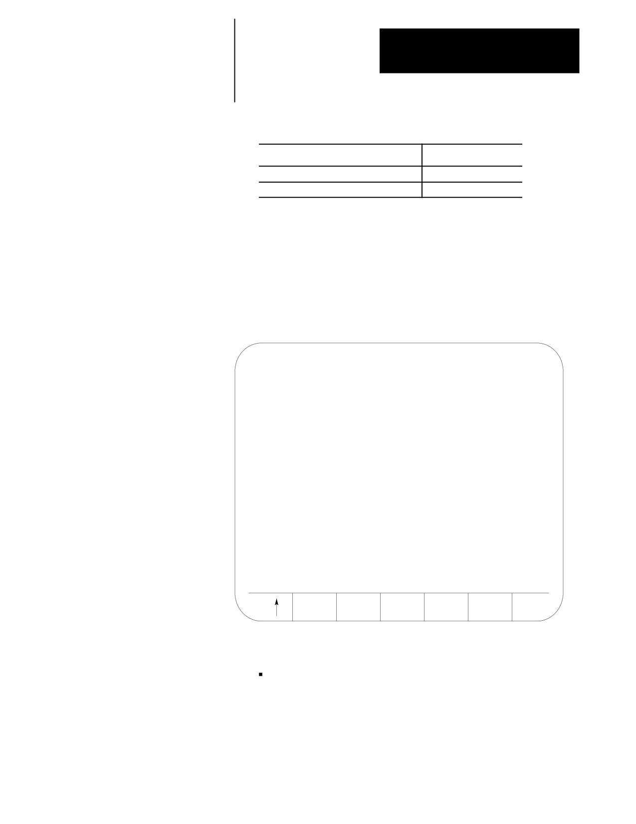
Select the device to copy from by using this table.
If the peripheral device is connected to:
Press this softkey:
Port A
{FROM A TO MEM}
Port B
{FROM B TO MEM}
The screen is changes to the “COPY PARAMETERS” screen
(Figure 9.3) and displays the current device and setup parameters for
that communication port.
If the device displayed on the screen is not correct, select the correct
device using the procedure described on page 9-1.
Figure 9.3
Copy Parameter Screen
COPY PARAMETERS
FROM:
(SELECTED PORT NAME)
TO:
(PROGRAM NAME)
DEVICE:
FACIT N4000
BAUD RATE:
2400
PROTOCOL:
LEVEL_2*
OUTPUT CODE:
ASCII
AUTO FILENAME:
NO
STOP PRG END:
YES
PROGRAM END:
M02, M30
M99
SINGLE
MULTI
PRGRAM
PRGRAM
6.
Specify if you want to copy one program or multiple programs.
Input Single Program
Press {SINGLE PRGRAM} to copy one program from tape. Input
terminates when the first program end or tape end code is
encountered.
9-11
Chapter 9
Communications
Input Multiple Programs
Press {MULTI PRGRAM} to copy multiple programs from the tape
into memory.
If STOP PRG END was set to
the tape reader
“yes”
stops each time it encounters a program end or
tape end code.
“no”
continuously reads programs until it encounters
a tape end code.
For details on how multiple programs are input and named, refer to
the AUTO FILENAME, STOP PRG END, and PROGRAM END
parameters discussed beginning on page 9-7.
When you input a program, the control does not erase the program
from the peripheral device. If the program being read contains a
comment in the first block, the control loads the comment and
displays it with the program name in the program directory.
If the selected program name already exists in control memory, the
following prompt appears: “OVERWRITE PROGRAM IN
MEMORY (Y/N):”
Type:
To:
“Y”
start the tape reader and overwrite the existing program in
memory with the new program
“N”
abort the copy operation
CAUTION: If you select overwrite, the control will erase the
existing program from its memory prior to replacing it with the
new program. If an error occurs during the input operation, or
you abort the copy operation, the original program will be lost,
and the new one will not be copied.
To abort the copy operation at any time, press the {CANCEL} softkey.
(softkey level 4)
CANCEL
9-12
Chapter 9
Communications
9.3
If a program is in control memory and you want to send a copy of that
program to a peripheral device, follow these steps:
Outputting Part Programs to
a Tape Punch
1.
Verify that the peripheral device is connected to the correct serial port
and that the port is configured for that device
(refer to page 9-1).
2.
Press the {PRGRAM MANAGE} softkey. The control displays the screen
shown in Figure 9.4.
(softkey level 1)
PRGRAM
OFFSET
MACRO
QUICK
SYSTEM
MANAGE
PARAM
CHECK
SUPORT
FRONT
ERROR
PASS-
SWITCH
PANEL
MESAGE
WORD
LANG
Figure 9.4
Program Directory Screen
SELECTED PROGRAM:
DIRECTORY
PAGE
1
OF
1
NAME
SIZE
COMMENT
O12345
1.3
SUB TEST 1
TEST
3.9
NEW
MAIN
1.3
TTTE
1.3
THIS IS A TEST PROGRAM
4 FILES
127.5
METERS FREE
ACTIVE
EDIT
RESTRT
DISPLY
COPY
PRGRAM
PRGRAM
PRGRAM
PRGRAM
PRGRAM
9-13
Chapter 9
Communications
3.
Press the {COPY PRGRAM} softkey.
(softkey level 2)
ACTIVE
EDIT
RESTRT
DISPLY
COPY
PRGRAM
PRGRAM
PRGRAM
PRGRAM
PRGRAM
VERIFY
PRGRAM
DELETE
RENAME
INPUT
PRGRAM
COMENT
PRGRAM
PRGRAM
DEVICE
REFORM
MEMORY
4.
Enter the program name to output from memory. There are two ways
to do this:
Type in the program name using the alphanumeric keys on the key
board. The control displays program name on the input line (line
2 of the screen) next to the prompt “FILENAME”.
Use the up or down cursor keys to position the cursor at the
program it is desired to send. The control displays the selected
program in reverse video.
If outputting all programs, cursor to the first program in your
program directory.
5.
Select the device you want to copy as follows:
If the peripheral device is connected to:
Press this softkey:
Port A
{MEM TO PORT A}
Port B
{MEM TO PORT B}
(softkey level 3)
MEM TO
FROM A
MEM TO
FROM B
MEM TO
PORT A
TO MEM
PORT B
TO MEM
MEM
The Copy Parameters screen appears (see Figure 9.5).
9-14
Chapter 9
Communications
6.
Specify if you want to output one, multiple, or all programs onto tape.
Output Single Program
Press {SINGLE PRGRAM} to output the program selected in
step 4.
Output Multiple Programs
Press {MULTI PRGRAM} to output more than one program. After
you pressed the {MULTI PRGRAM} key, the program selected in step
4 is output. The Program Directory Screen (see Figure 9.4)
appears with the following set of softkeys:
(softkey level 4)
OUTPUT
FINISH
PRGRAM
TAPE
Select the next program to output by selecting the file name
as described in step 4. Press the {OUTPUT PRGRAM} key to
output the program.
For details on how multiple programs are named, refer to
chapter 10 and the end of page 9-7.
CAUTION: Be aware that the information in the directory such
as program name and comment are not output to tape. If you
want to transfer this information to tape, you must include the
program name and comment from the directory in the first
block of the program. Refer to chapter 10 for details on “O”
word program name.
After the last program is output to the tape, press
{FINISH TAPE} to punch the tape end and trailer code to the
tape.
Important: If an error occurs or you abort the copy
operation while punching a tape, the tape may not be useable.
Output All Programs
Press {OUTPUT ALL} to copy all programs in memory to tape at
one time.
{OUTPUT ALL} works like {MULTI PRGRAM} except that you
cannot select the programs you want to output.
{OUTPUT ALL} selects all programs automatically and outputs
them to the peripheral device.
9-15
Chapter 9
Communications
All programs are copied to the peripheral device and stored
using the same program name as the original, in the order that
they appear on the Program Directory Screen.
(softkey level 3)
SINGLE
MULTI
OUTPUT
PRGRAM
PRGRAM
ALL
Figure 9.5
Copy Parameters Screen
COPY PARAMETERS
FROM:
(Program Name)
TO:
(Selected Port Name)
DEVICE:
FACIT N4000
BAUD RATE:
2400
PROTOCOL:
LEVEL_2*
OUTPUT CODE:
ASCII
AUTO FILENAME:
NO
STOP PRG END:
YES
PROGRAM END:
M02, M30
M99
CANCEL
Important: Press {CANCEL} to abort the copy operation at any time.
9-16
Chapter 9
Communications
9.4
To verify that a part program stored in memory matches a source program
stored in memory or on a peripheral device:
Verifying Part Programs
Against Source Programs
1.
If one of the programs to either verify or verify against is on a
peripheral device, make sure that the peripheral device is connected
to the correct serial port and that the port is configured for that device
(refer to page 9-1).
2.
Press the {PRGRAM MANAGE} softkey.
(softkey level 1)
PRGRAM
OFFSET
MACRO
QUICK
SYSTEM
MANAGE
PARAM
CHECK
SUPORT
FRONT
ERROR
PASS-
SWITCH
PANEL
MESAGE
WORD
LANG
3.
Press the {VERIFY PRGRAM} softkey.
(softkey level 2)
ACTIVE
EDIT
RESTRT
DISPLY
COPY
PRGRAM
PRGRAM
PRGRAM
PRGRAM
PRGRAM
VERIFY
PRGRAM
DELETE
RENAME
INPUT
PRGRAM
COMENT
PRGRAM
PRGRAM
DEVICE
REFORM
MEMORY
4.
Type program name(s) into the input area (lines 1- 2) in the following
manner. If both programs are resident in control memory, type both
program names separated by a comma. The order in which these
names are entered is not important.
VERIFY: program name,program name
If one of the programs to verify is on a peripheral device and the
other is resident in control memory, it is only necessary to type the
name of the program resident in the control.
VERIFY: program name
9-17
Chapter 9
Communications
5.
To verify a part program in memory against a part program stored on
a peripheral device, press the {VERIFY PORT A} or {VERIFY PORT B}
softkey depending on where the peripheral device is connected.
To verify a part program in memory against another part program in
memory, press the {VERIFY MEMORY} softkey.
(softkey level 3)
VERIFY
VERIFY
VERIFY
PROT A
PORT B
MEMORY
6.
Press the {VERIFY YES} softkey. To abort the verify operation press
the {VERIFY NO} softkey.
(softkey level 4)
VERIFY
VERIFY
YES
NO
The control displays one of the following messages when the verify
operation is performed:
“PROGRAMS ARE DIFFERENT” if programs do not match.
“PROGRAMS ARE IDENTICAL” if programs match.
9.5
An error occurs if you attempt these operations:
Error Conditions (Inputting
output data to an input device (tape reader, etc.)
and Outputting Part
Programs)
output or input data when no peripheral device is connected to the
selected port
output or input data when the data communication line is either broken
or not connected
input data from an output device (tape puncher, etc.)
input a program name that already exists in control memory. The
control displays “OVERWRITE PROGRAM IN MEMORY(Y/N):”
input a program without reading in or typing in a filename when AUTO
FILENAME is set to “no”
END OF CHAPTER
9-18

Chapter
10
Introduction to Programming
10.0
The 9/Series control performs machining operations by executing a series
of commands that make up a part program. These commands are
Chapter Overview
interpreted by the control which then directs axis motion, spindle rotation,
tool selection, and other CNC functions.
Part programs can be executed from the control’s memory or from a CNC
tape.
This chapter begins with an explanation of CNC tape format. The
remainder of the chapter deals with the contents of a part program,
including:
Topic:
On page:
Tape format
10-1
Program configuration
10-6
Program names
10-8
Sequence numbers
10-9
Subprograms
10-11
Word formats and functions
10-16
Word descriptions
10-20
10.1
This section describes the format that the control requires for inputting and
Tape Format
outputting part programs from or to a tape device.
The control accepts:
ASCII format (RS-358B)
EIA-244-B format
Important: In addition to the control’s normal tape format, it is also
equipped to read and execute standard Allen-Bradley 7320 and 7360 CNC
tapes. See appendix D of this manual for details.
10-1
Chapter 10
Introduction to Programming
Tape with Program End = M02, M30, M99
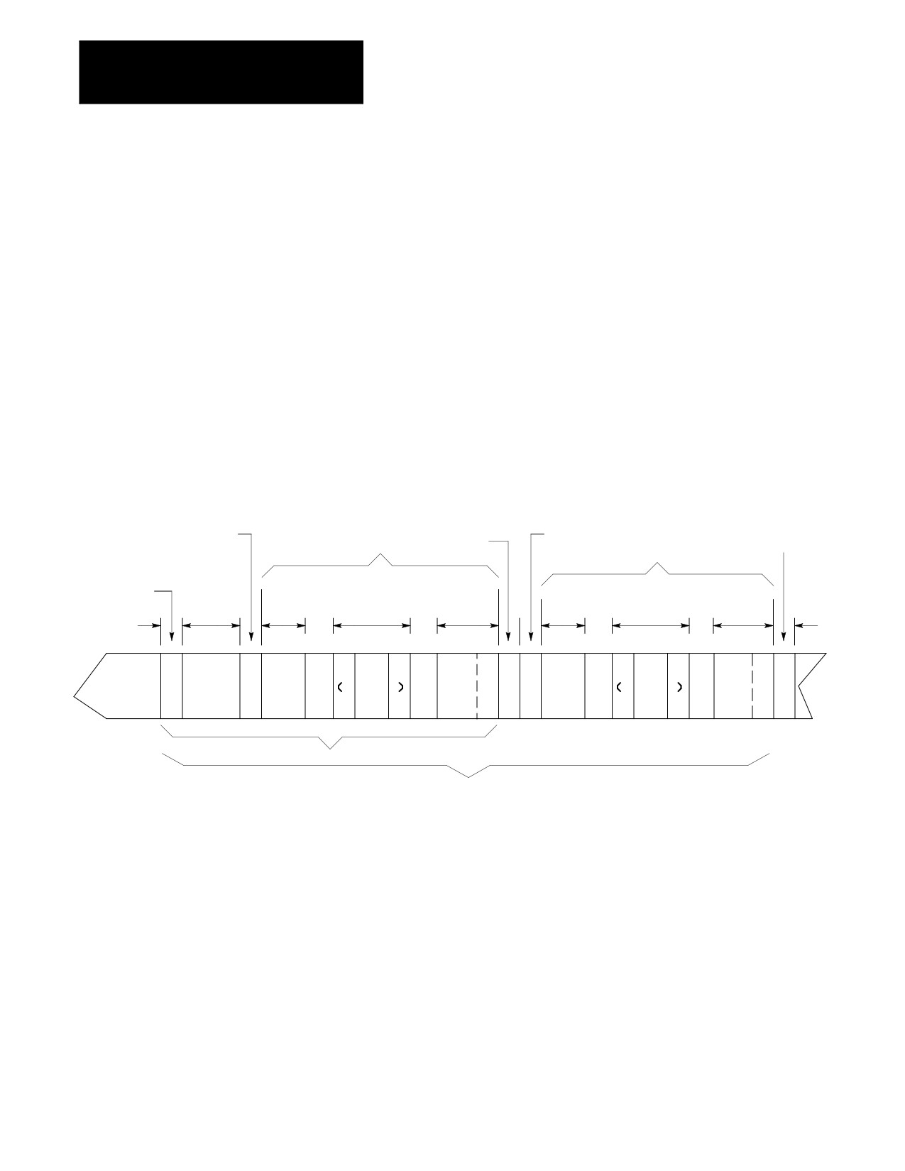
This particular tape format allows single- or multi-program format on a
tape. It also lets you enter either M02, M30, or M99 as a program end
code. See chapter 10 for details on legal program end codes. Figure 10.1
shows a typical configuration for a multiple program tape with M30 and
M99 as program end codes.
If the first block of the file program is a filename, you can set AUTO
FILENAME to “yes” to create filenames for all subsequent programs. If
AUTO FILENAME is set to “no” and if no filenames are included in the
programs on the tape, you have to enter all filenames from the keyboard
when prompted. For more information, see the section on O-word
programming in this chapter.
The control automatically recognizes EIA or ASCII during input when it
reads the first EOB code from the tape.
Figure 10.1
Tape Configuration (Program End = M02, M30, M99)
Program start code
1 foot
Program start code
Tape end
Part program
space
code
Part program
Tape start
Program
Program
code
Leader
Comment
Program
Comment
Program
name
name
section
(opt)
end code
(opt)
end code
(opt)
(opt)
E
E
E
E
E
E
R
O
O100
M30
O
O
O101
M99
O
R
or
B
B
B
B
or
%
%
Typical single program tape
Typical multi-program tape
10-2