9/Series CNC Lathe. Operation and Programming Manual - page 11
Chapter 10
Introduction to Programming
(12) Synchronization with Setup (M150-M199)
M150 - M199 — Synchronization with Setup
(dual-process system only)
This set of M-codes cancels any information already in block look
ahead and re-setup the blocks before process execution is resumed.
This re-setup is only essential when shared information is being changed
from one process to another, as in the case of the dual processing
paramacro parameters. See page 30-7.
Important: You cannot use these M-codes when TTRC is active.
Other more specific M-codes are described in later sections that deal
specifically with their functions.
Important: When you activate the MISCELLANEOUS FUNCTION
LOCK feature, the control displays M-, B-, S-, and T-words in the part
program and activates the corresponding Tool Wear Offset, with the
exception of M00, M01, M02, M30, M98, M99 and M100-M150.
10.5.7
Your system installer may decide to use the 2nd miscellaneous functions to
distinguish a set of miscellaneous functions from the normal M-code
2nd Miscellaneous Function
miscellaneous functions. This manual assumes the B-word is used to call
(B-Word)
second auxiliary functions. Any alphabetic character which is not used for
other functions may be used instead of B by setting the proper AMP
parameter. For details, refer to documentation prepared by your system
installer, or the AMP programmers manual.
The B-word is designated by a 2- or 3-digit numeric value following
address B. Unlike M-codes, each block can contain only one B-word.
Important: When you activate the MISCELLANEOUS FUNCTION
LOCK feature, the control displays M-, B-, S-, and T-words in the part
program and activates the corresponding Tool Wear Offset, with the
exception of M00, M01, M02, M30, M98, and M99. This feature is
described in section 7.1.2.
10.5.8
Each block in a part program can be assigned up to a 5-digit numeric value
following an N address. These numbers are referred to as sequence
N-Words (Sequence
numbers and are used to distinguish one block from another.
Numbers)
Sequence numbers can be assigned at random to specific blocks or to all
blocks if desired. Blocks assigned sequence numbers can be called later by
designating their sequence number. Sequence numbers are necessary to
make program jumps and to specify a block for subprogram calls and
returns. For details on sequence number, see section 10.2.2.
10-33
Chapter 10
Introduction to Programming
10.5.9
The O-word is used to define a program name. To use an O word as a
program name it must be the first block entered in a program. This block
O-Words (Program Names)
can be used to identify a program when reading from a tape (when
program name is selected as “automatic” from the device setup menu).
This is useful when many programs are placed together on a single tape.
An O-word can have up to 5 numeric characters following it.
10.5.10
When the same series of blocks are repeated more than once it is usually
easier to program them using a subprogram.
P,L Words (Main Program
Jumps and Subprogram
This section explains:
Calls)
Main and subprograms
Subprogram calls
Important: To make jumps, loops, or calculations within an executing
program or subprogram, use any of the paramacro features described in
chapter 28.
P-words in a subprogram call (M98) or paramacro call are used to
designate the specific program being called. The P address is followed by
the program name being called.
L-words in a subprogram call (M98) and some cycles are used to designate
a repeat count for a subprogram. The number following the L address
designates the number of times a subprogram is executed consecutively
before execution is returned to the main program.
For details on subprograms, see section 10.3.
10.5.11
The spindle function has two modes:
S-Words (Spindle Speed)
Spindle Mode:
Function:
Constant Surface Speed Mode (G96)
maintains a workpiece’s speed across a tool equal to a desired
cutting speed independent of the diameter.
Constant Spindle RPM Mode (G97)
maintains a constant spindle speed equal to the designated
S-word making the actual cutting speed dependant on the
working diameter.
Spindle speed and cutting speed values are programmed designated by an
S-word, followed by up to 4 digits. S-words are modal and remain active
until you designate another S-word is designated. Use a common S-word
to program all of the spindles AMPed to be in the system.
10-34
Chapter 10
Introduction to Programming
Important: Your system installer sets a maximum speed in AMP for each
gear range for each spindle configured in AMP. If an S-word is
programmed requesting a spindle speed that exceeds this limit. The
spindle speed holds at the AMP-defined maximum. A new value may be
set for this maximum RPM by programming a G92 code followed by an
S-word. See chapter 17.
When programming an S-word in a block that contains axis motion
commands, the PAL program has the option to temporarily suspend the
axis motion commands until the spindle reaches speed. The control has the
ability to take the programmed spindle speed and automatically search for
the gear range that is AMPed to allow the necessary RPM. The operation
of gear changing and how it is implemented is very PAL dependant. Refer
to your system installers documentation for details on how a gear change
operation is performed.
For details on programming spindle speeds, see chapter 17.
Important: When you activate, the MISCELLANEOUS FUNCTION
LOCK feature, the control displays M-, B-, S-, and T-words in the part
program and activates the corresponding Tool Wear Offset, with the
exception of M00, M01, M02, M30, M98, and M99. This feature is
activated as described on section 7.1.2.
Override spindle speeds designated in a program with the
<SPINDLE SPEED OVERRIDE> switch on the MTB panel. This switch
can be positioned in five percent increments within a range of 50 - 120
percent. For details, refer to your system installers instruction manual.
Use the override cancel M-code (M49) to ignore any override set on the
MTB panel. When the override setting is ignored, the axis feedrate, rapid
feedrate, and the spindle speed values are all set to 100 percent. For more
information on spindle functions, see chapter 17.
10-35
Chapter 10
Introduction to Programming
10.5.12
Modern machining processes usually require a machine that is capable of
selecting different tools. Typically tools are mounted in a turret and
T-Words (Tool Selection and
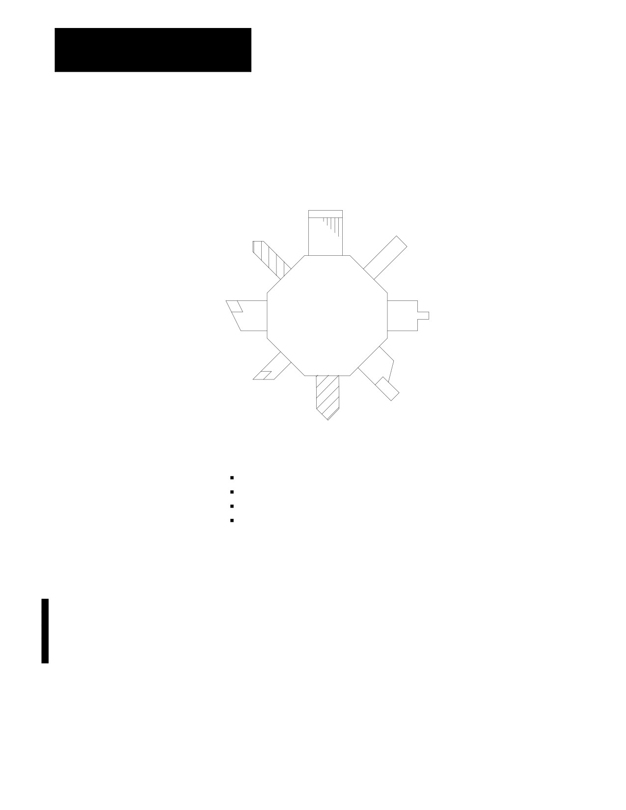
assigned tool numbers as illustrated in Figure 10.6.
Tool Length Offset)
Figure 10.6
Typical Tool Turret
07
06
08
05
01
04
02
03
These data are set in the offset table corresponding to different offset
numbers:
tool length offset data
tool tip radius data
tool wear compensation data
tool orientation data
See chapter 3.
The selection of a tool number and an offset number for that tool is done
by programming a T-word.
Important: When you activate the MISCELLANEOUS FUNCTION
LOCK feature, the control displays M-, B-, S-, and T-words in the part
program and activates the corresponding Tool Wear Offset, with the
exception of M00, M01, M02, M30, M98, and M99. This feature can be
activated through the front panel screen as described in chapter 2.
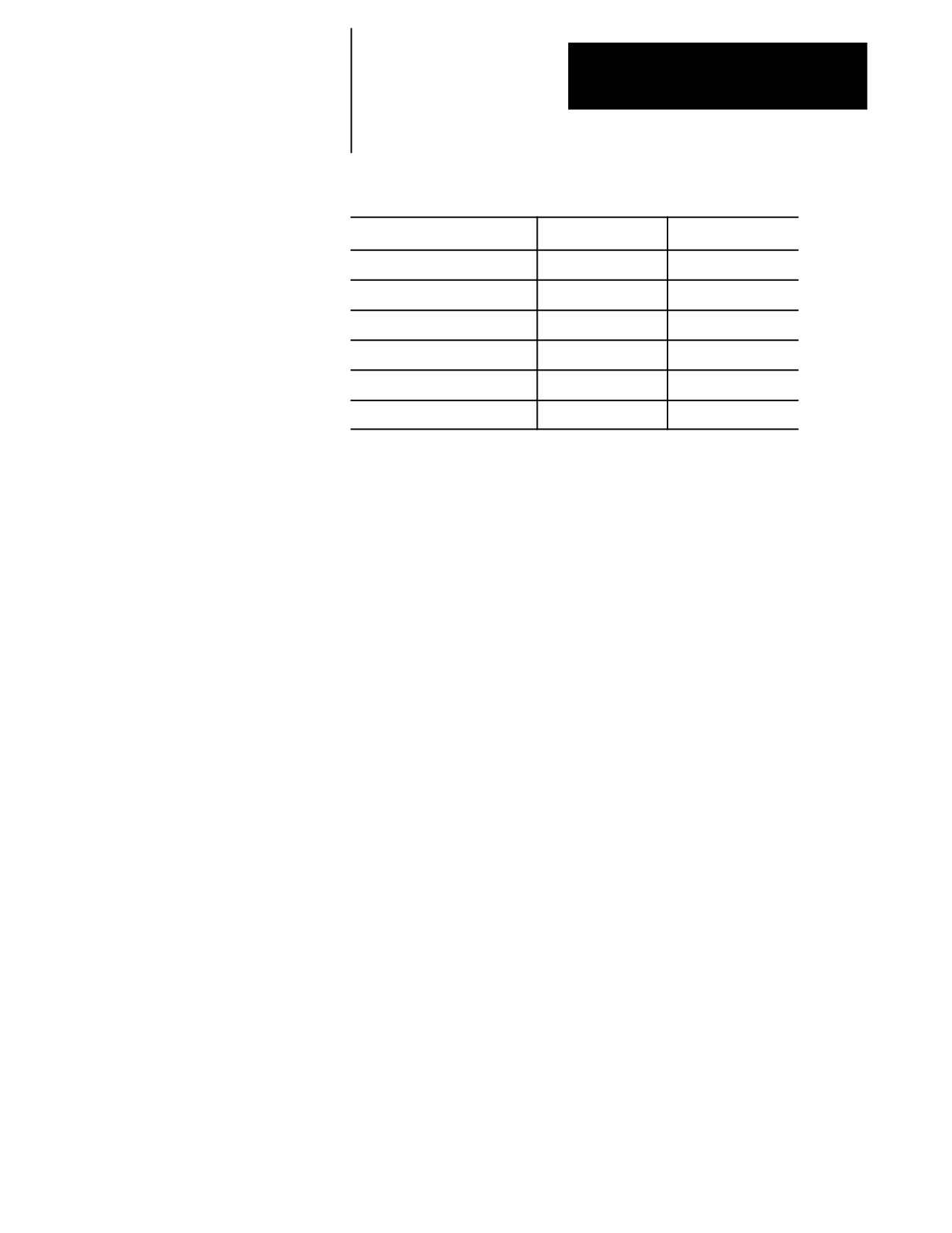
The format for a T-word is determined in AMP by the system installer. Six
format selections are available as shown in Table 10.G.
10-36
Chapter 10
Introduction to Programming
Table 10.G
T-word Formats
Format Type
Wear Offset #
Geometry Offset #
(1) 1 DGT GEOM + WEAR
last digit
same as wear
(2) 2 DGT GEOM + WEAR
last two digits
same as wear #
(3) 3 DGT GEOM + WEAR
last three digits
same as wear #
(4) 1 DGT WEAR
last digit
same as tool #
(5) 2 DGT WEAR
last two digits
same as tool #
(6) 3 DGT WEAR
last three digits
same as tool #
For details on programming a T-word discussing tool length offsets, see
chapter 20.
END OF CHAPTER
10-37
Chapter
11
Coordinate System Offsets
11.0
This chapter covers the control of the coordinate systems on the 9/Series
control. G-words in this chapter are among the first programmed because
Chapter Overview
they define the coordinate systems of the machine in which axis motion is
programmed. This chapter describes:
Information about:
On page:
Machine coordinate system
11-1
Preset Work coordinate systems G54-59.3
11-4
Work coordinate systems external offset
11-10
Offsetting the work coordinate systems
11-13
PAL offsets
11-22
A thorough understanding of this group makes programming easier by
allowing full control of the coordinate systems.
11.1
The 9/Series control has two types of coordinate systems.
Machine (Absolute)
Coordinate System
Coordinate System:
Description:
work coordinate system
defined based on the coordinate system used in the part
drawing of a part to be cut by the machine. Programs are
usually written based on the work coordinate system.
machine coordinate system
unique to the individual machine tool.
(often referred to as the absolute
coordinate system)
The machine coordinate system is the basic coordinate system set for every
machine. It is established after completion of the machine-homing
operation. It cannot be offset or shifted in anyway. Its position is
determined in AMP by your system installer.
Important: Before you can activate any coordinate system, the machine
must be homed. The homing operation refers to the positioning of the axes
to a machine-dependent, fixed position which is called the machine home.
For more on machine homing, refer to page 4-9.
The zero point of the machine coordinate system is referenced from the
machine home point. This is done by assigning a coordinated location to
the machine home point. The home position for each axis can be given
any legal coordinates, such as 15.00, -20.0000, or -2.256.
11-1
Chapter 11
Coordinate System Offsets
Once you establish, the machine coordinate system is not affected by a
control reset operation or any other programming or operator operation.
Figure 11.1
Machine Coordinate System, Home Coordinate Assignment
+X
10
Mechanically fixed
Machine Home
point
Chuck
+Z
15
Machine Coordinate System
zero point
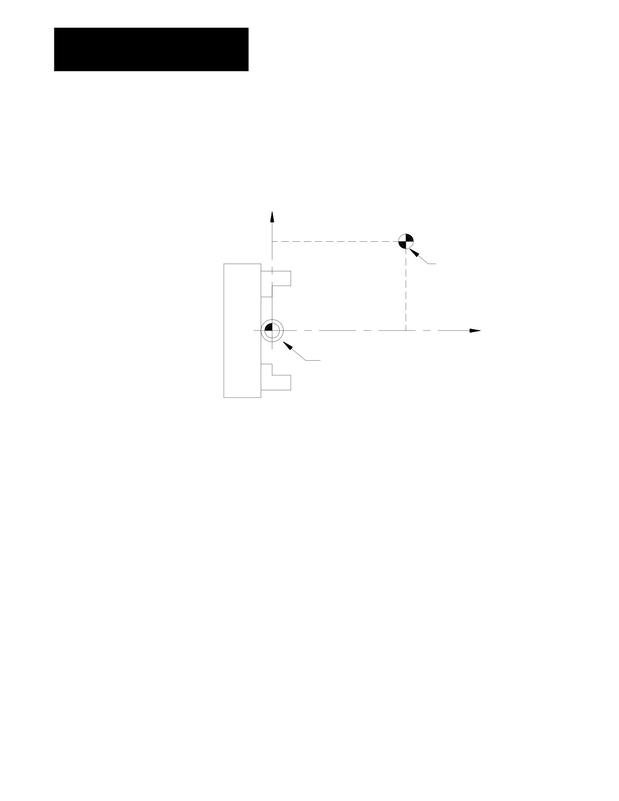
In Figure 11.1, your system installer defined the machine coordinate
system zero point by assigning the machine home point to have the
coordinates X=10 and Z=15.
The coordinate values assigned to the machine home point do not affect the
position of machine home. The position of machine home is fixed by your
system installer.
Important: Normally, the control displays the current axes positions in
respect to active work coordinate system. The position in the machine
coordinate system can be displayed by selecting the absolute screen as
described in chapter 8.
11-2
Chapter 11
Coordinate System Offsets
11.1.1
Although axis motion is usually commanded in the work coordinate
system, axis motion is possible when a G53 is programmed in a block if
Motion in the Machine
you reference coordinate values in the machine coordinate system.
Coordinate System (G53)
G90G53X___Z___;
The X- and Z-words above specify coordinate positions in the machine
coordinate system. These coordinate values indicate the end point of the
next move in the machine coordinate system. The tool travels to this
position in either G00 or G01 mode, depending on which is active when
the G53 block is executed. Any attempt to execute a G53 block in G02 or
G03 mode generates an error.
The G53 code is not modal. It is effective only in the block in which it is
called. After a G53 block, the control returns to the coordinate system that
was in effect prior to the G53 blocks execution.
Important: The control must be in absolute mode (G90) when the G53
command is executed. If a G53 is executed while in incremental mode
(G91), the control ignores the G53 code and any axis words in the G53
block.
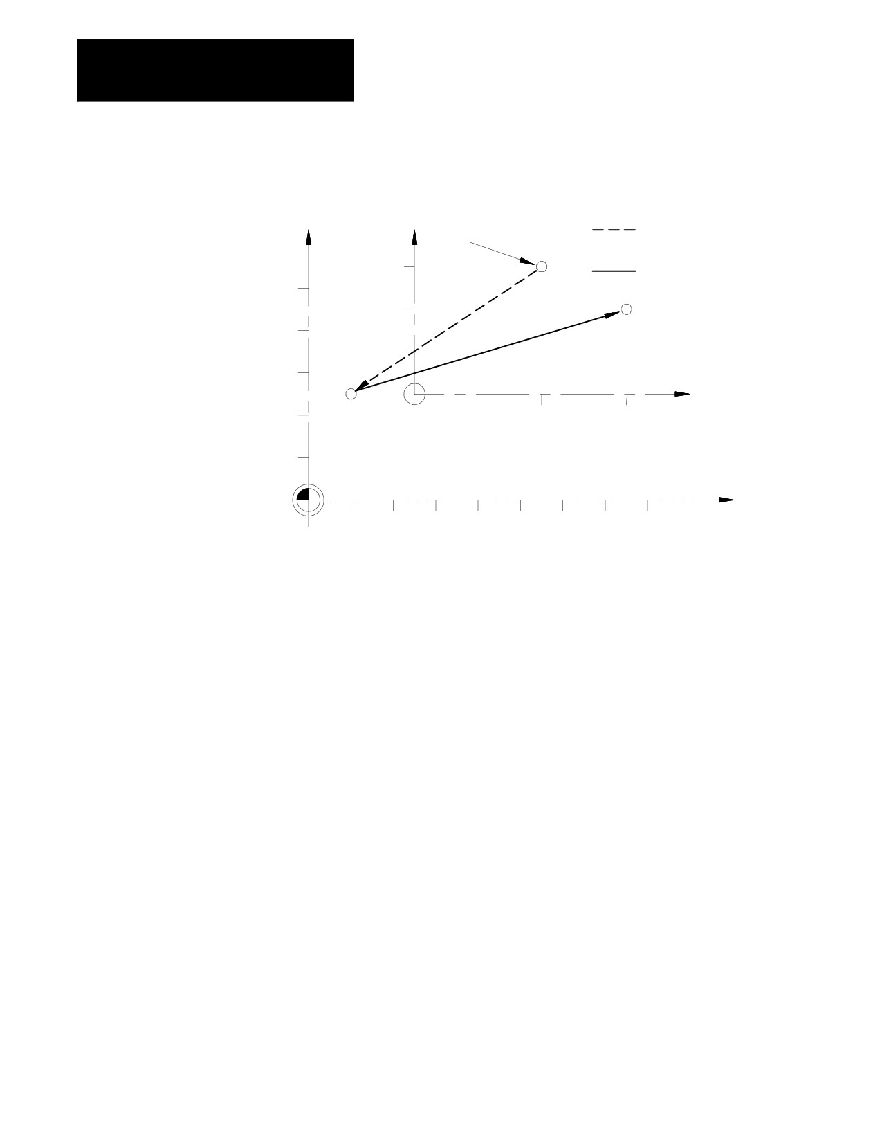
Example 11.1
Motion In The Machine Coordinate System.
Program block
Comment
N1 G00X30Z30;
axis motion in work coordinate system.
N2 G53X25Z10;
axis motion in machine coordinate system.
N3 X20Z50;
axis motion in work coordinate system.
11-3
Chapter 11
Coordinate System Offsets
Figure 11.2
Results of Example 12.1
X
X
Axis motion in machine
coordinate system
30
N1
Axis motion in work
coordinate system
50
20
N3
40
30
Work coordinate system
Z
N2
20
30
50
10
Machine coordinate system
Z
10
20
30
40
50
60
70
80
11.2
When you cut a workpiece using a part program made from a part drawing,
you want to match the zero point on the coordinate system of the part
Preset Work Coordinate
drawing with the zero point of the work coordinate system.
Systems (G54-59.3)
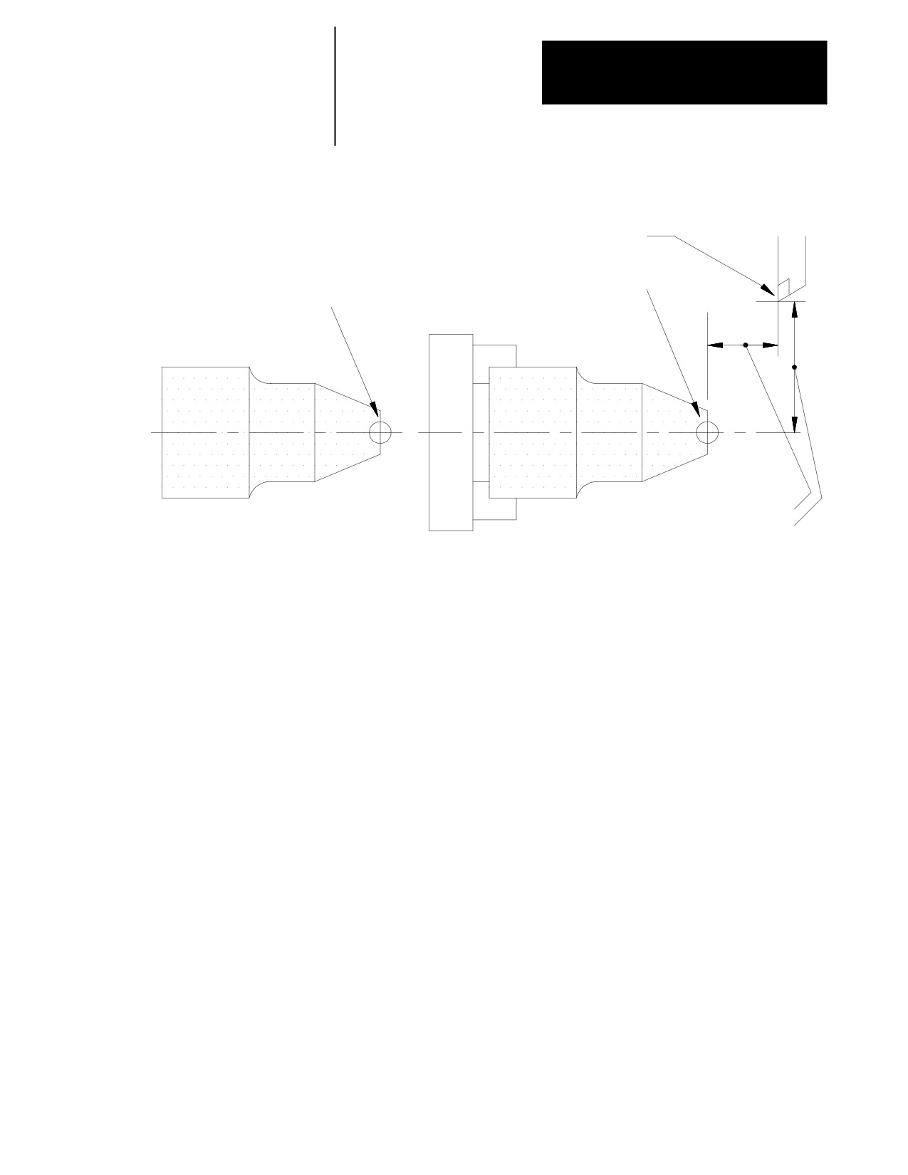
As shown in the illustrations in Figure 11.3, you establish the work
coordinate system by programming the distance between the desired zero
point of the work coordinate system and the zero point of the machine
coordinate system.
11-4
Chapter 11
Coordinate System Offsets
Figure 11.3
Work Coordinate System
Tool position at
machine coordinate zero point
Zero point on the work
Zero point on
coordinate system
the part drawing
Chuck
Workpiece
Workpiece
Z Distance to be designated
X Distance to be designated
There are 7 preset work coordinate systems selected using G54 - G59.3.
The required work coordinate system can be selected by specifying any of
these G-codes in the program.
Work coordinate systems called out by G54 - G59.3 have zero points that
you enter in a work coordinate system table (see page 4.3). These zero
points are in the form of offset values from the machine coordinate system
zero point.
The control establishes the machine coordinate system immediately after
you complete the machine home operation The default work coordinate
system, determined in AMP by your system installer, is activated
simultaneously. The default work coordinate system is established when
you execute a control reset operation, E-STOP, G92.1, or power up. The
default work coordinate system is the sum of the external offset value (if
any), and the offsets of the default coordinate system selected in AMP
(G54-G59.3 or none). If the default coordinate system is selected as none,
the default work coordinate system is simply the external offset (if any).
This manual assumes G54 to be the default coordinate system and no
external offset has been entered.
11-5
Chapter 11
Coordinate System Offsets
Figure 11.4
Work Coordinate System Definition
X
X
G54 Work coordinate system
2
Z
-3
Z
3
-2
Machine coordinate system
Machine home
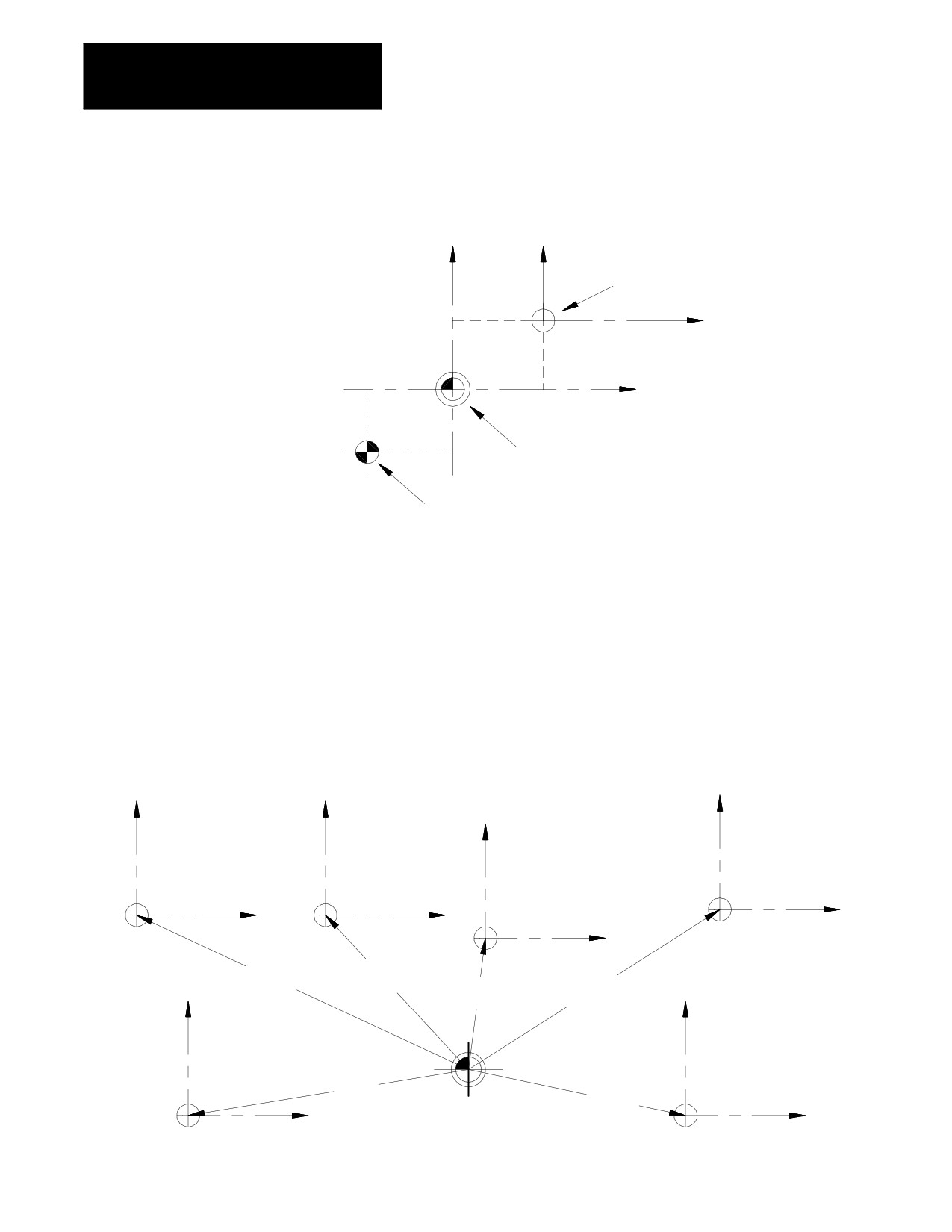
In Figure 11.4, the machine coordinate system was defined by declaring
the fixed position machine home as the point X=-3., Z=-2. Then the G54
work coordinate system zero point was defined by the coordinates X=2,
Z=3 in the machine coordinate system.
Coordinate positions in a part program are manipulated as coordinate
values in the default work coordinate system, unless another coordinate
system is selected by programming G54-G59.3.
Figure 11.5
Examples of Work Coordinate System Definition
X
X
X
X
G58
G55
G56
G57
Z
Z
Z
Z
X+3.3
X+3.3
Z-3.1
X+2.9
X+3.5
X
Z-7.2
X
Z+.4
Z+5.5
G54
G59
X-1.0
Z-6.1
X-1.0
Z+4.8
Z
Z
Machine coordinate system zero point
11-6
Chapter 11
Coordinate System Offsets
To change work coordinate systems, specify the G-code corresponding to
the work coordinate system you want in a program block. Any axis
motion commands in a block that contains a change from one work
coordinate system to another is executed in the work coordinate system
specified in that block.
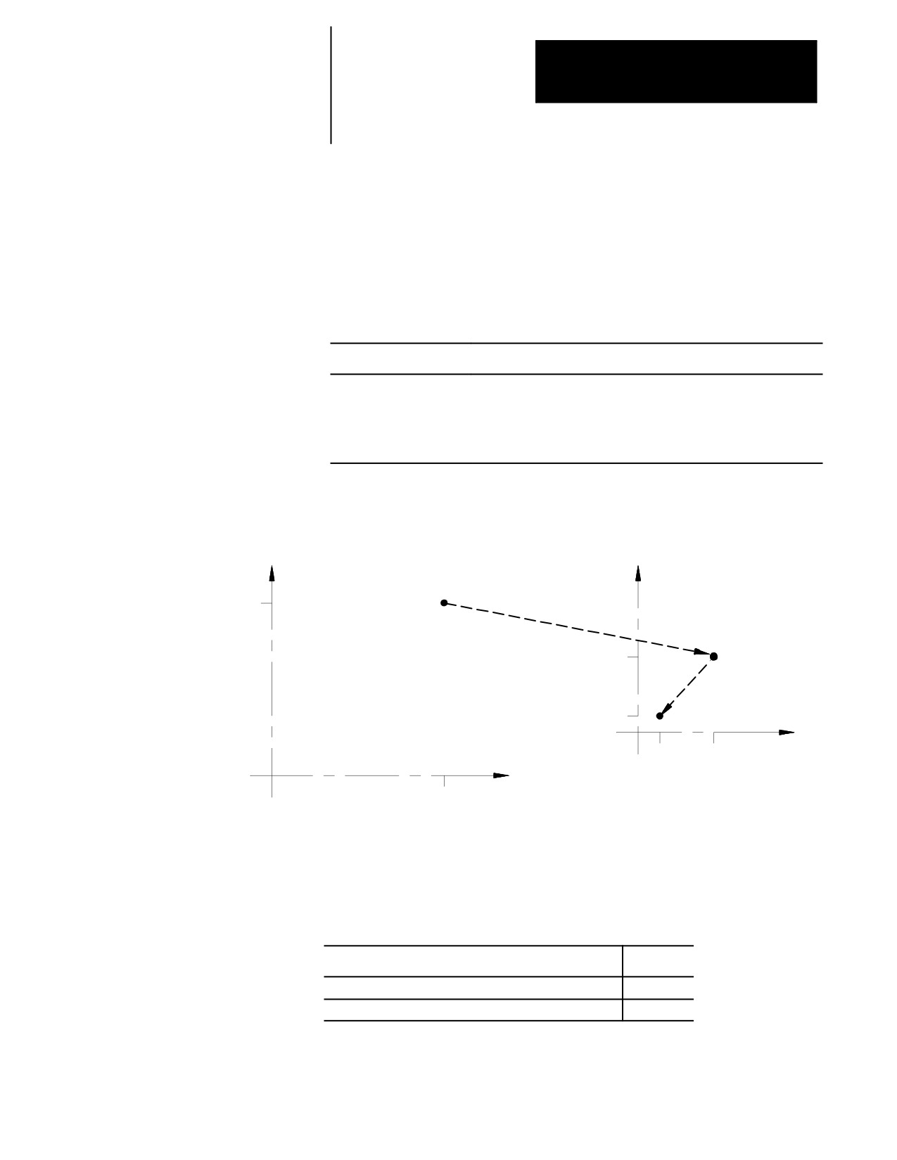
Example 11.2
Changing Work Coordinate Systems
Program Block
Comment
G54;
G00X20.Z20.;
axis motion in the G54 work coordinate system.
G55X10.Z10.;
axis motion to the point X10. Z10. in the G55 work coordinate system.
X2.Z3.;
axis Motion in the G55 work coordinate system.
Figure 11.6
Results of Example 12.2
X
X
20
10
2
Z
G54 Work Coordinate System
3
10
Z
G55 Work Coordinate System
20
11.2.1
There are 3 methods to change the value of a work coordinate system zero
point in the work coordinate system table. Two methods can be found in
Altering Work Coordinate
the following sections:
Systems (G10L2)
Method:
Chapter:
manually alter the work coordinate system table
3
alter the paramacro system parameter values 5221- 5386
28
11-7
Chapter 11
Coordinate System Offsets
The third method, and the one described in this section, alters the work
coordinate system table through G10 programming. Changing the values
in the table using any of these methods does not cause axis motion. It does
immediately shift the active coordinate system by the amount entered. The
format for altering the work coordinate systems using G10 is:
G10 L2 P__ O__ X__ Z__;
Important: The order of the words in this program block is important.
The L, P, and O words must be programmed before any axis words are
programmed in the G10 block. Failing to follow this order can result in
data being misinterpreted and loaded into the table incorrectly.
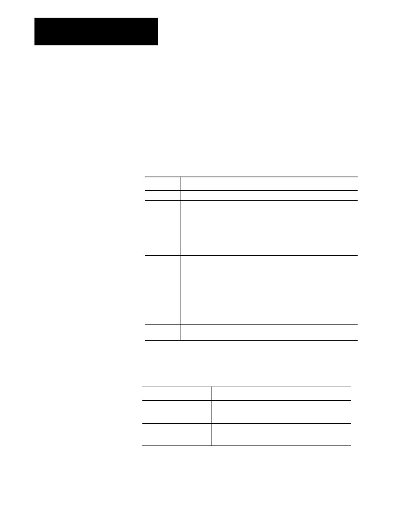
Where :
Is :
L2
tells the control that you want to alter the coordinate system tables.
P__
specifies which coordinate system (G54 through G59.3) you want to work on. P1
through P9 correspond to the work coordinate systems G54 through G59.3.
P1 = G54 work coord. system
P6 = G59 work coord. system
P2 = G55 work coord. system
P7 = G59.1 work coord. system
P3 = G56 work coord. system
P8 = G59.2 work coord. system
P4 = G57 work coord. system
P9 = G59.3 work coord. system
P5 = G58 work coord. system
O__
specifies whether the value entered for the diameter axis is a radius or diameter
value. (O is non-modal.)
O1=value entered for the diameter axis is a radius value.
O2=value entered for the diameter axis is a diameter value.
Important: If you program O1 or O2 in a G10 code, the G10 code is not
affected by a previously programmed G07 or G08 (radius/diameter
programming). However, if no O-code is specified, or if the O-code is out of
range (for example, O3), then the G10 code is affected by a G07/G08.
X_Z_
specify the location of the zero point of the specified work coordinate system
relative to machine coordinate system.
Important: G10 blocks cannot be programmed when TTRC is active.
Incremental/Absolute Mode and the G10L2 Command
When you program in:
Then:
incremental mode (G91)
any values entered into the work coordinate system table using
the G10 command are added to the currently active work
coordinate system values.
absolute mode (G90)
any values entered into the work coordinate system table using
the G10 command replace the currently active work
coordinate system values.
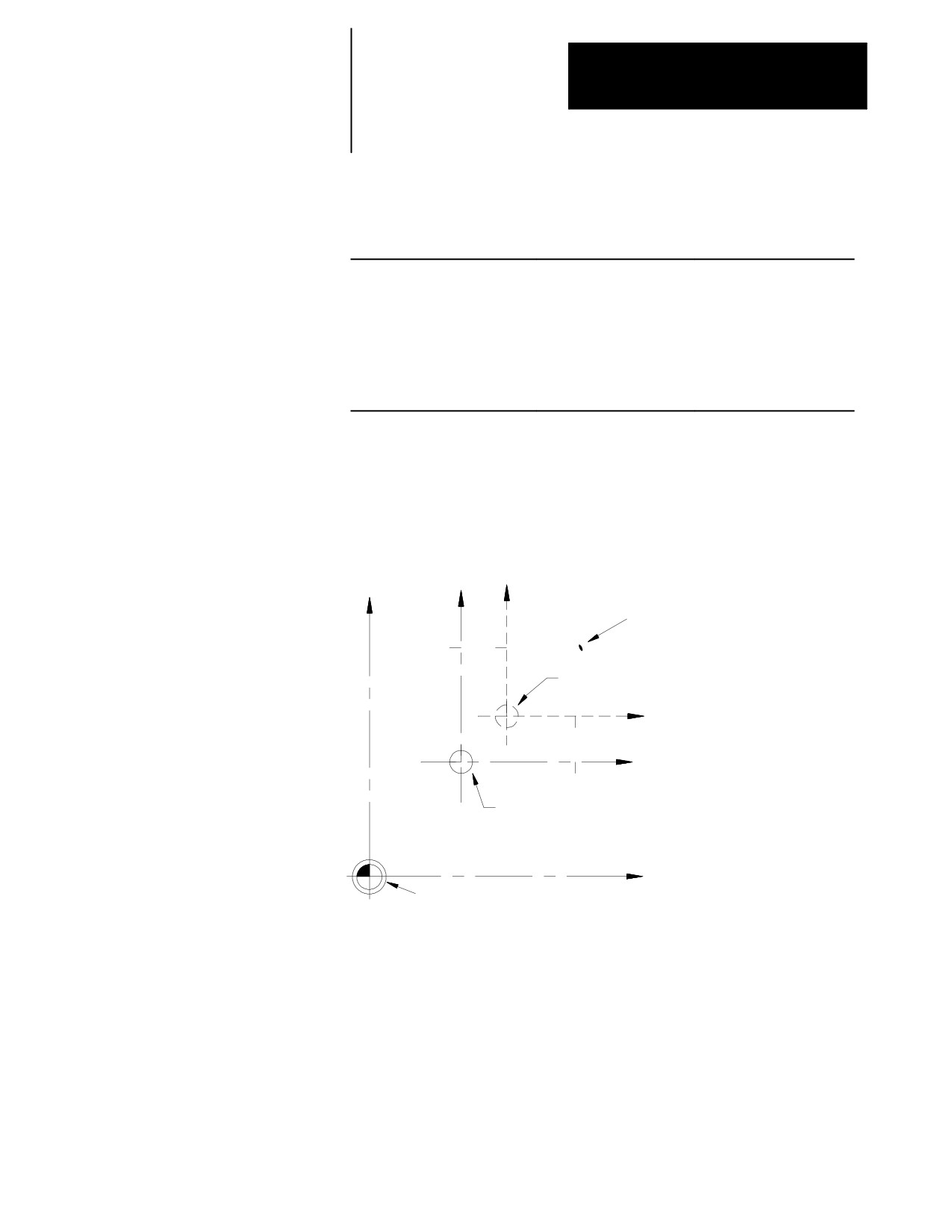
Example 11.3 and Figure 11.7 illustrate how the work coordinate system is
shifted by using G10.
11-8
Chapter 11
Coordinate System Offsets
Example 11.3
Work Coordinate System Shift Using G10
Program block
Work coordinate Position Absolute coord. Position
G54G01X25.Z25.;
X25 Z25
X50 Z45
G91;
G10L2P1O2X10.Z10.;
X15 Z15
X50 Z45
or
G54G01X25.Z25.;
X25 Z25
X50 Z45
G90;
G10L2P1O2X35.Z30.;
X15 Z15
X50 Z45
Important: This modification is permanent. The new table values for the
work coordinate systems are saved even when control power is turned off.
Figure 11.7
Results of Example 12.3
X
X
X
Tool position
50
25
15
G54 Work coordinate system
40
after changing table value
Z
30
15
Z
20
25
G54 Work
coordinate system
20
30
40
50
Z
Machine coordinate system zero point
11-9
Chapter 11
Coordinate System Offsets
11.3
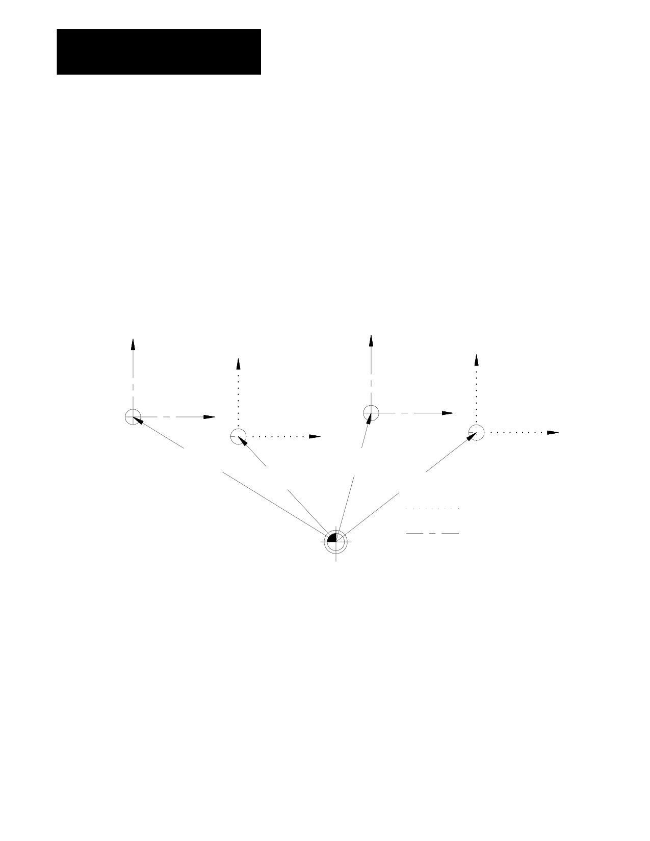
The external offset allows all work coordinate system zero points to be
shifted simultaneously, relative to the machine coordinate system. This
Work Coordinate System
offset can compensate for part positioning shifts that result when a
External Offset
different chuck is installed. It can also compensate for tool position shifts
that result from a different tool turret.
The external offset can also be used to match the work coordinate systems
on mechanically different machines. The machines can then use the same
part program with the same G54-G59.3 coordinate values. This allows
part programs to be less machine dependant.
Figure 11.8
External Offsets
X
X
X
X
G54
G56
G56
G54
Z
Z
Z
Z
X+4.0
X+4.1
Z-6.5
Z+1.1
X+3.3
X+3.4
Z-3.1
Z+4.5
Work coordinate systems
prior to external offset
Work coordinate systems
Machine coordinate
after to external offset of
system zero point
X.7 Z-3.4
Important: Once an external offset is entered into the coordinate offset
table it cannot be canceled. This offset remains active even after power
has been turned off. It becomes a permanent part of all work coordinate
systems including the default work coordinate system.
11-10
Chapter 11
Coordinate System Offsets
11.3.1
There are 3 methods to change the value of an external offset in the work
coordinate system table. Two methods can be found in the following
Altering External Offset
sections:
(G10L2)
Method:
Chapter:
manually alter the external offset value in the work
3
coordinate system table
alter the paramacro system parameter values 5201- 5206
28
The third method, and the one described in this section, alters the external
system table through G10 programming. Changing these values in the
table using any of these methods does not cause axis motion. It does
immediately shift the active coordinate system by the amount entered.
The values entered into the external offset are added to the work coordinate
system zero point values each time a work coordinate system is called.
The format for altering the external offset using G10 is:
G10 L2 P0 O__ X__ Z__;
Where :
It :
L2
tells the control that you want to alter the coordinate system tables.
P0
designates the external offset as the offset to update.
O__
specifies whether the value entered for the diameter axis is a radius or diameter
value. (O is non-modal.)
O1=value entered for the diameter axis is a radius value.
O2=value entered for the diameter axis is a diameter value.
Important: If you program O1 or O2 in a G10 code, the G10 code is not
affected by a previously programmed G07 or G08 (radius/diameter
programming). However, if no O-code is specified, or if the O-code is out of
range (for example, O3), then the G10 code is affected by a G07/G08.
X_Z_
specifies the location of the zero point of the specified work coordinate system
relative to machine coordinate system.
When you execute this block, the control immediately shifts the currently
active work coordinate system by the new external offset amount.
Example 11.4 and Figure 11.9 illustrate how the work coordinate system is
shifted using G10.
11-11
Chapter 11
Coordinate System Offsets
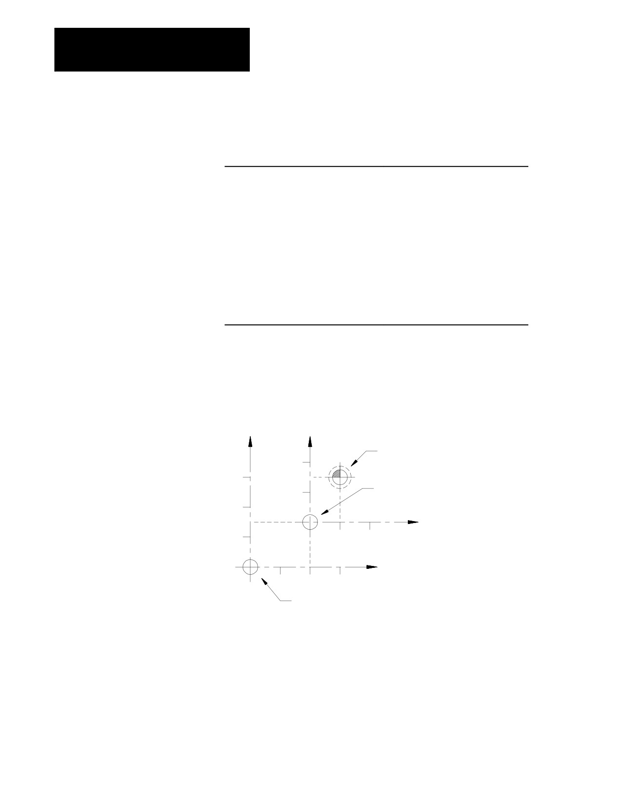
Example 11.4
Changing the External Offset Through G10 Programming
Program Block
Comments
G10L2P1O1X-15.Z-10.;
defines work coordinate system zero
point to be at X-15, Z-10 from the
machine coordinate system zero point
G90;
sets external offset of X-15, Z-20 moving
G10L2P0O1X-15.Z-20.;
work coordinate system zero point to be
at X-30, Z-30 from the machine
coordinate system zero point
G90;
sets external offset of X-30, Z-30 moving
G10L2P0O1X-30.Z-30.;
work coordinate system zero point to be
at X-30, Z-30 from the machine
coordinate system zero point
Important: This modification is permanent. The new table values for the
work coordinate systems are saved even when control power is turned off.
Figure 11.9
Results of Example 11.4
X
X
Machine coordinate system
20
zero point
30
Work coordinate system
10
zero point as defined in
20
table to be X-15., Z-10.
Z
10
10
20
Z
10
20
30
Work coordinate system zero point after
execution of the block G10L2P0X-15.Z-20.;
11-12
Chapter 11
Coordinate System Offsets
11.4
This section describes the more temporary ways of offsetting the work
coordinate systems. These offsets are activated through programming, and
Offsetting the Work
they are canceled when you remove power to the control. They may also
Coordinate Systems
be cancelled by an M02, M30, or control reset, depending upon the
selections made in AMP by your system installer.
Important: All of these offsets are global in nature. This means that they
apply to all work coordinate systems. When you change work coordinate
systems (programming G54-G59) consider the effects of these offsets on
the new work coordinate system.
Tool geometry and wear offsets are not effected by an offset made to the
work coordinate system.
Important: We recommend that tool offsets for geometry and wear be
canceled before you execute any work coordinate system offsets. If tool
offsets are not canceled, the work coordinate system offset is added to the
active tool offset. This can cause confusion when you change tool offsets
later in the program. See page 20-5 on canceling tool offsets.
11.4.1
Use the G92 command in a part program to offset the currently active work
Coordinate Offset Using
coordinate system relative to the current tool position. A G92 block in a
program offsets the zero point of the work coordinate system a specified
Tool Position (G92)
distance from the current tool position.
G92.2 cancels G92 without canceling any other work coordinates. This
differs from G92.1, which cancels all coordinate system offsets. A control
reset may cancel this offset, depending upon the selections made in AMP
by your system installer.
When a G92 command is executed in a program, it cancels any other active
work coordinate system offsets that may have been in effect including G52
offsets, jogged offsets, or set zero offsets. External offsets are not affected.
When the PAL flag $INHR is set, it cancels G92.
Important: A tool offset is not automatically canceled when you execute a
G92 block. This can result in undesired effects on the work coordinate
system when tool offsets are changed later.
The following G92 block offsets the work coordinate system so that the
current tool position takes on the coordinate values programmed in the
G92 block.
G92 X___ Z___;
11-13

Chapter 11
Coordinate System Offsets
For example specifying values of zero for all axes in a G92 block causes
the current tool position to become the zero point of the current work
coordinate system.
Execution of a G92 block does not produce any axis motion.
Important: Any axis not specified in the G92 block is not offset, and the
current coordinate position for that axis remains unchanged.
Once the work coordinate system is offset, all absolute positioning
commands in the program are executed as coordinate values in the offset
coordinate system.
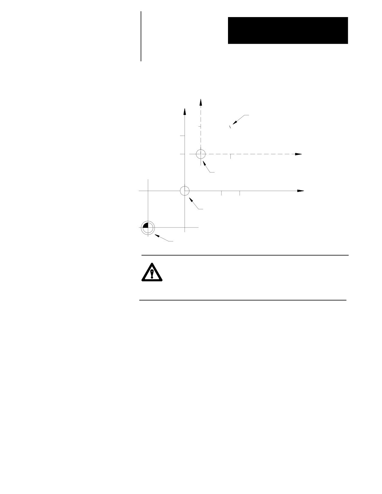
Example 11.5
Work Coordinate System Offset (G92)
Program Block
Comment
G54 G00;
G54 work coordinate system
X35. Z25.;
rapid move to X35, Z25 in the G54 work
coordinate system
G92X10.Z10.;
Redefines current axis position to have
the coordinates X10, Z10
The zero point of the offset G54 work coordinate system is 10 units away
from the current tool location in both the X and Z directions. If the Z
value had not been entered in the G92 block, the Z coordinate location
would have remained unchanged (Z25.)
11-14
Chapter 11
Coordinate System Offsets
Figure 11.10
Results of Example 12.5
X
X
Tool position
10
30
20
Z
10
New zero point established
by the G92 block
Z
20
30
Zero point for the G54
work coordinate system
Machine coordinate system zero point
CAUTION: G92 offsets are global. Changing from one
coordinate system to another does not cancel the offset. Do not
specify a change in coordinate systems (G54-G59.3) unless the
effects of the offset have been considered.
Example 11.6 shows the effect of changing work coordinate systems while
the G92 offset is active.
11-15
Chapter 11
Coordinate System Offsets
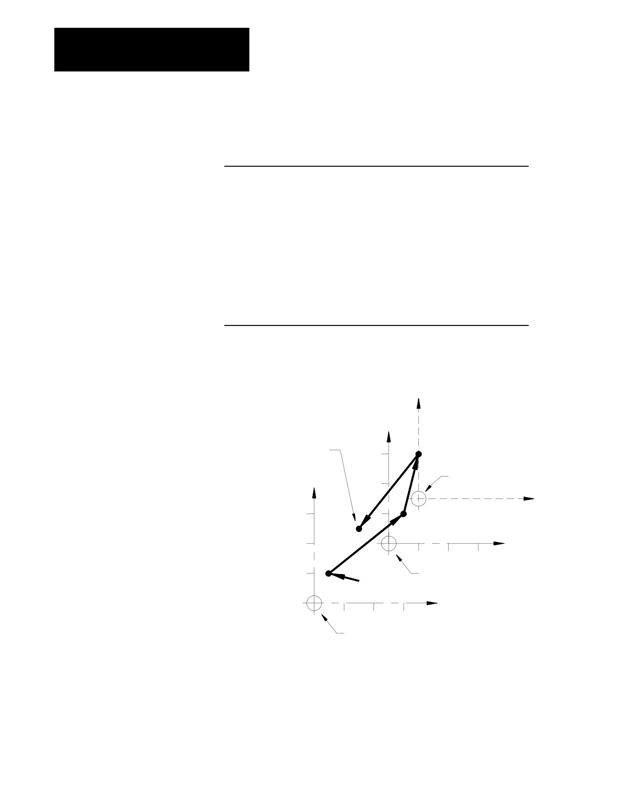
Example 11.6
Changing Work Coordinate Systems With Offset Active
Program
Comment
N1 G10L2P1X0Z0;
Define G54 work coordinate system zero point to be
positioned X0, Z0 away from the machine
coordinate system
N2 G10L2P2X20.Z25.;
Define G55 work coordinate system zero point to be
positioned X20, Z25 away from the machine
coordinate system
N3 G55X10.Z5.;
Move to X10, Z5 in the G55 work coordinate system
N4 G54X10.Z5.;
Move to X10, Z5 in the G54 work coordinate system
N5 G92X-5.Z-5.;
Offset current tool position to be at X-5, Z-5
N6 X15.Z0.;
Move to X15, Z0 (offset still active)
N7 G55X10.Z5.;
Move back to X10, Z5 in the G55 work coordinate
system with the G92 offset still active
Figure 11.11
Results of Example 12.6
Y
Final move to Y10, X5
Y
after G92 offset was
activated in previous
work coordinate system
30
N6
New zero point established
Y
by the G92 block
X
N7
30
N4
20
X
10
20
30
10
N3
Zero point for the G54
work coordinate system
X
10
20
30
Zero point for the G55
work coordinate system
In Figure 11.11, the offset entered for the G54 work coordinate system has
also shifted the G55 coordinate system. Any offsets described in this
section alter all of the work coordinate system (G54 - G59) at the same
time.
11-16
Chapter 11
Coordinate System Offsets
11.4.2
To offset a work coordinate system an incremental amount from its zero
point, program a G52 block that includes the axis names and distances to
Offsetting Coordinate Zero
be offset.
Points (G52)
G52 X___ Z___ ;
This command offsets the current work coordinate system by the axis
values that follow the G52 command.
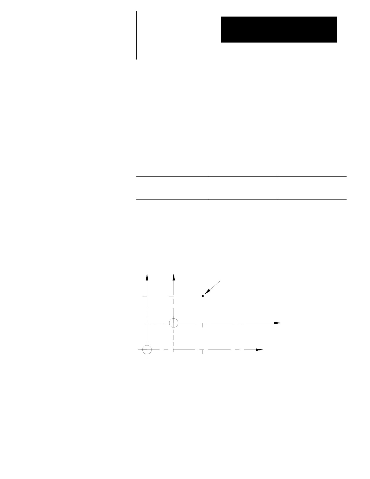
Example 11.7
Work Coordinate System Offset by G52
Program Block
Machine Coordinate Position Work Coordinate Position
G01X25.Z25.;
X25 Z25
X25 Z25
G52X10.Z10.;
X25 Z25
X15 Z15
In this example no axis motion takes place when the G52 block is
executed. The work coordinate system position values change. See
Figure 11.12.
Figure 11.12
Results of Example 11.7
X
X
Tool position
25
15
Work coordinate system
after G52 offset
10
Z
15
Original work coordinate system
Z
10
25
The G52 work coordinate system zero point offset can be canceled by
programming a G52 block with zero values for the axes to be cancelled.
The following block would cancel the work coordinate system offset for
the X axis only.
G52 X0;
11-17
Chapter 11
Coordinate System Offsets
A G52 offset can also be canceled by executing a G92 or G92.1,
performing a control reset or an E-STOP reset operation, or executing an
end of program M30 or M02. A G92 command only cancels a G52 offset
if one is active when the G92 block is executed. A G52 offset can be
activated at some time after the G92 block is executed even if a G92 offset
is still in effect.
CAUTION: G52 offsets are global. Changing from one
coordinate system to another does not cancel the offset. Do not
specify a change in coordinate systems (G54-G59) unless the
effects of the offset have been considered.
11.4.3
When you perform a Set Zero operation, the control shifts the current work
{SET ZERO} Offset
coordinate system so that the current tools position is the zero point of the
coordinate system. The axis where you want to perform a set zero on is
selected through PAL (refer to your system installer’s documentation) or
by the current jog axis if using the {FRONT PANEL} option.
The Set Zero offset is similar to the execution of a G92 X0 Z0 block, with
one exception. Unlike a G92, the set zero does not cancel a G52 offset.
The G52 remains active and continues to offset the current tool position in
the work coordinate system. When the G52 offset is canceled later, the
coordinate system shifts.
The Set Zero offset can be canceled by programming a G92.1 command,
executing a control reset operation, executing an E-STOP reset operation,
or programming an end of program M30 or M02 command. A control reset
may cancel the Set Zero offset, depending upon the selections made in
AMP by your system installer.
CAUTION: Set Zero offsets are global. Changing from one
coordinate system to another does not cancel the offset. Do not
specify a change in coordinate systems (G54-G59) unless the
effects of the offset have been considered.
11-18
Chapter 11
Coordinate System Offsets
Example 11.8
Typical Set Zero Offset Application
Operation
Comment
-Manual jog-
axes are manually jogged to a location where the operator has
determined that a special operation must be performed.
-Set Zero-
operator performs a Set Zero offset to establish the work coordinate
system zero point at the current axis location
-Run program-
a generic special operation program can now be executed from the
axis coordinate position that resulted from the manual jog and Set
Zero
The set zero offset can be performed through an optional switch installed
by your system installer or through the {SET ZERO} softkey as described
on page 2-13 on using the {FRONT PANEL} softkey.
11.4.4
The jog offset feature lets you manually create a desired offset by jogging
the axes during an automatic or MDI operation.
Jog Offset
Important: This feature functions only if your system installer has
supplied a special switch and the appropriate PAL programming. See the
“Jog Offsets” and “Jog-on-the-fly” PAL flags in the PAL reference manual
or refer to the documentation supplied by your system installer.
Press a special switch after interrupting an automatic or MDI operation to
activate this feature. Any manual jog moves you make are added to the
current work coordinate position as an offset. When you press cycle start
to continue execution, the jogged distance for each axis remains as a
coordinate offset for that axis.
CAUTION: Jog offsets are global. Changing from one
coordinate system to another does not cancel the offset. Do not
specify a change in coordinate systems (G54-G59) unless the
effects of the offset have been considered.
You can cancel the jog offset by programming a G92.1 command,
executing a control reset operation, executing an E-STOP reset operation,
or programming an end of program M30 or M02 command.
11-19
Chapter 11
Coordinate System Offsets
To use this feature, follow these steps:
1.
Press <CYCLE STOP> or <SINGLE BLOCK> on the MTB panel to
interrupt automatic or MDI operation.
2.
Turn on the switch to activate the jog offset feature (refer to
documentation provided by your system installer).
3.
Change to manual mode, unless the control is equipped for the
“Jog-on-the-Fly” feature which allows jogging in automatic or MDI
modes (refer to documentation prepared by your system installer).
4.
Jog the axes using any of the available jog types (with the exception
of homing) as described on page 4-1. The control adds the amount of
the jog move as an offset for each jogged axis.
5.
Return to Automatic or MDI mode. When you press the <CYCLE
START> button, execution continues from the new tool location at
the jogged offset.
Important: When you move the jog offset, the axis position displays do
not change on the screen unless the currently active screen is displaying
absolute position coordinates. This is because the coordinate values in the
work coordinate system are being offset as the axes are being jogged.
11.4.5
The G92.1 command cancels these offsets:
Canceling Coordinate
G92 work coordinate system offset
System Offsets (G92.1)
G52 zero point offset
{SET ZERO} offset
Jog offset
Reset G54 - G59.3 coordinate system to default condition
It does not cancel an external offset. See page 11-10.
The G92.1 block also reestablishes the default work coordinate system as
set in AMP by your system installer. It cancels or activates the coordinate
system (G54-G59.3) as set in AMP to establish the default coordinate
system.
You must program the G92.1 block with no axis words. Axis words in a
G92.1 block generate an error. When you execute the G92.1 block, all
G92, G52, {SET ZERO}, and Jog offsets are canceled on all axes. You
cannot cancel the offsets on only one or more of the axes.
No axis motion takes place during execution of a G92.1 block. Axes
remain at their last programmed positions while the work coordinate
system adjusts to remove all offsets.
11-20
Chapter 11
Coordinate System Offsets
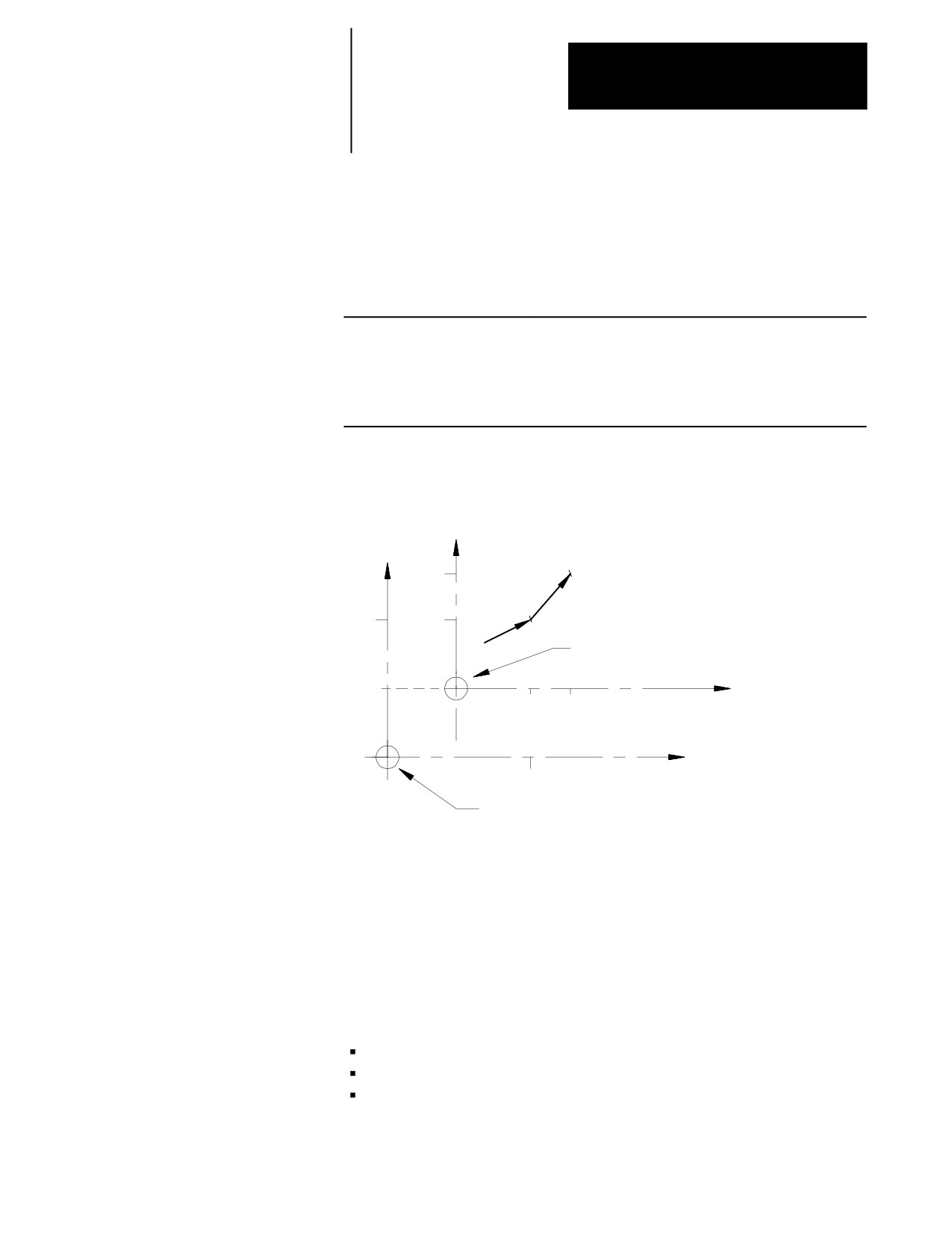
Example 11.9 demonstrates the G92.1 offset cancel.
Example 11.9
G52 Offset Cancelled By a G92.1
Program Blocks
Comment
N1 G01Y25.X25.;
move to Y25, X25
N2 G52Y10.X10.;
work coordinate system is offset by Y10, X10
N3 Y25.X25.;
move to Y25, X25 in the offset coordinate system
N4 G92.1;
G52 offset is cancelled, program position displays axis position
at X35Y35.
Figure 11.13
Results of Example 12.9
Y
Y
25
N3
N1
25
15
Work coordinate system zero
point after G52 offset
10
X
15
25
X
10
25
Original work coordinate system zero point,
and work coordinate system after G92.1
11.4.6
The G92.2 command cancels these offsets:
Canceling Selected
G92 work coordinate system offset
Coordinate System Offsets
{SET ZERO} offset
(G92.2)
Jog offset
It does not:
cancel an external offset
reset the current work coordinate system (G54-G59.3)
cancel a G52 offset
11-21
Chapter 11
Coordinate System Offsets
The G92.2 block must be programmed with no axis words. Axis words in
a G92.2 block generate an error. When you execute the G92.2 block, all
G92, {SET ZERO}, and Jog offsets are canceled on all axes. You cannot
cancel the offsets on only one or more of the axes.
No axis motion takes place during execution of a G92.2 block. Axes
remain at their last programmed position while the work coordinate system
adjusts to remove these offsets.
11.5
Your system installer has the option of activating, deactivating, or altering
PAL Offsets
the value of these offsets through PAL:
Work coordinate systems
External offset
Tool length offsets (geometry and wear)
Tool tip radius offsets (geometry and wear)
Tool orientation
These offsets can be modified through a PAL display page created by your
system installer or through some other input to PAL.
There can be an impact on the activation of offsets if a part program is
already active for automatic execution. Typically, any blocks that have
been read into the control’s look-ahead buffer use the newly modified
offset value. If a cutter compensation offset has been modified by PAL,
the control does not update the look-ahead buffer unless the offset is
currently active. Refer to documentation supplied by your system installer
for details on specific PAL offset operations.
END OF CHAPTER
11-22
Chapter
12
Overtravels and Programmable Zones
12.0
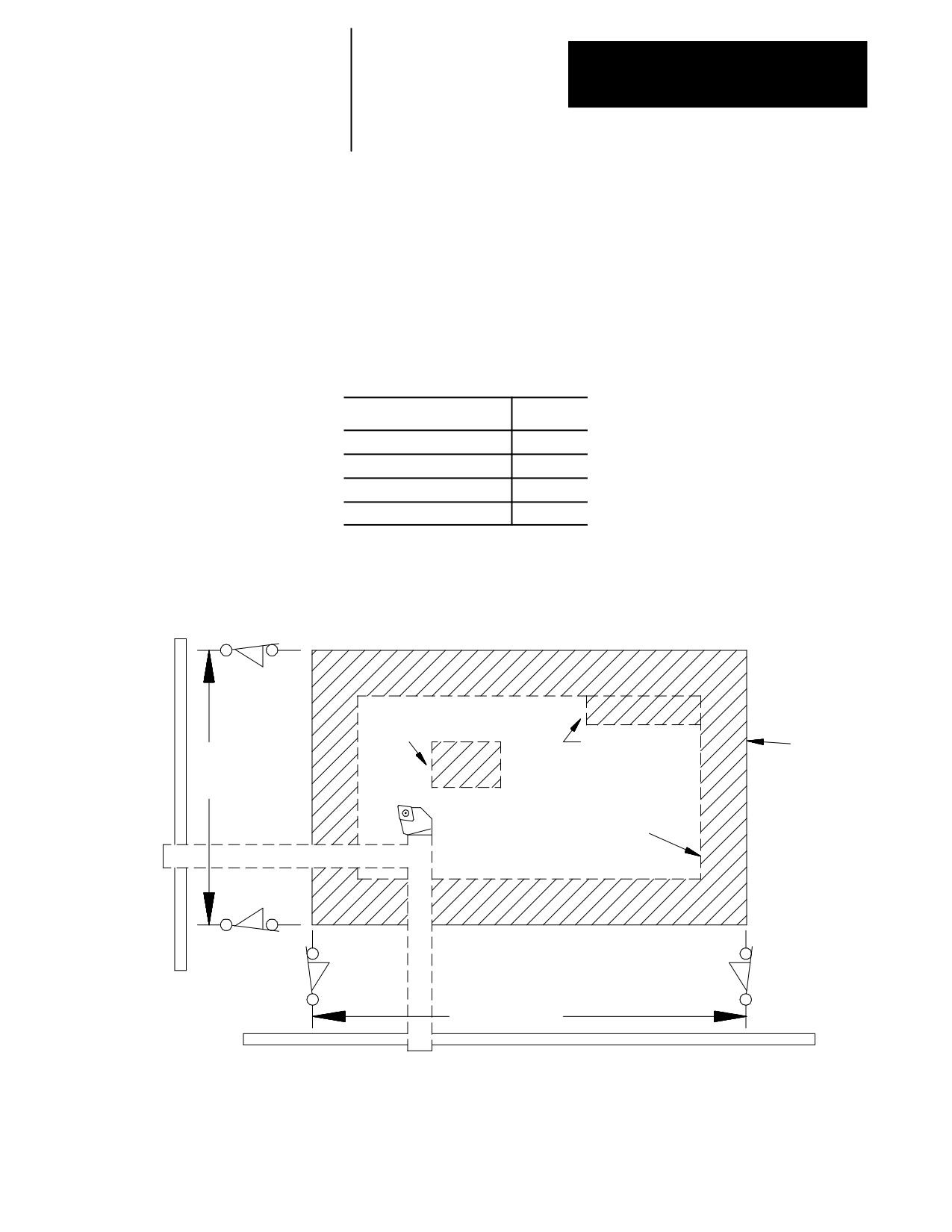
Overtravels and programmable zones define areas that restrict the movable
range of the cutting tool. The 9/Series control is equipped to establish two
Chapter Overview
overtravel areas and two programmable zones as illustrated in Figure 12.1.
Topic:
On page:
Hardware overtravels
12-2
Software overtravels
12-3
Programmable zone 2
12-5
Programmable zone 3
12-7
Figure 12.1
Overtravels
Limit switch
Programmable
zone 2
Programmable
Hardware
zone 3
overtravel
X axis
travel
Cutting
Software
tool
overtravel
Limit switch
Limit switch
Limit switch
Z axis travel
12-1
Chapter 12
Overtravels and Programmable Zones
There are two types of overtravels:
Hardware overtravels ---- Established by your system installer by
mounting mechanical limit switches on the movable range of the axes
Software overtravels ---- Established in AMP by your system installer
designating coordinate values in the machine coordinate system
There are two types of Programmable Zones.
Zone:
Description:
Programmable Zone 2
Established by the operator, or person in charge of job setup. The
machine coordinate system boundaries for this zone are entered in a
table. Programmable zones may be turned on and off in the part
program.
Programmable Zone 3
Established by the operator, programmer, or person in charge of job
setup. The machine coordinate system boundaries for this zone are
entered in a table or through programming. Programmable zones
may be turned on and off in the part program.
Dual processing systems also have a feature that is intended to prevent
collision between moving axes of the machine. This feature is called
interference checking and is discussed in chapter 30.
12.1
When the machine tool is set up your system installer should have installed
a set of two mechanical limit switches on each axis. These limit switches
Hardware Overtravels
are installed in a position so that when the machine attempts to move
beyond a range determined by your system installer the limit switch is
tripped. When the limit switch is tripped axis motion stops. The area
defined by these limit switches is referred to as the hardware overtravel.
CAUTION: The area defined by a hardware overtravel does
not take into account any tool offsets. This can allow the actual
tool to enter the restricted area without the axes entering it.
These switches are installed to prevent the machine from motion that
exceeds a range that can cause damage to the machine. Frequently your
system installer wires the hardware overtravel directly into the E-STOP
string. This stops all motion and disables the axis drives. Refer to the
literature provided by your system installer for instructions on moving axes
out of hardware overtravel.
12-2