9/Series CNC Lathe. Operation and Programming Manual - page 13
Chapter 14
Axis Motion
14.1.2
The format for linear interpolation mode is:
Linear Interpolation Mode
G01X ____ Z ____ F ____ ;
(G01)
Where :
Is :
G01
G01 establishes the linear interpolation mode. In linear interpolation mode, the
cutting tool is fed along a straight line at the currently programmed feedrate.
XZ
This is the location of the end point of the linear move in the current work
coordinate system.
F
The F-word represents the feedrate for axis moves that take place in the G01,
G02, and G03 modes. The F-word does not have to be programmed in the G01
block however, if the F-word is not programmed a feedrate must have been made
active in some previous block.
Linear interpolation can be performed in the absolute mode (G90), or the
incremental mode (G91).
Example 14.2
Linear Interpolation
Absolute command
Incremental command
G08;
G08;
G90G01X30.Z60.F.1;
G91G01X10.Z-65.F.1;
Figure 14.2
Results of Linear Interpolation (G01), Example 14.2
X
65
60
30
20
Z
14-3
Chapter 14
Axis Motion
Once the feedrate, F, is programmed it remains effective until another
feedrate is programmed (F is modal). You can override programmed
F-words. For details, see chapter 18.
Example 14.3
Modal Feedrates
Program Block
Comment
G91G01X10.Z20.F.1;
F.1 is effective until
Z35.;
another feedrate is
X40.Z35.;
programmed
Z44.F.3;
F.3 is effective
The feedrate for a multi-axis move is specified as the vectorial feedrate.
The control adjusts the individual axis feeds to obtain the programmed
feedrate. For details on feedrates, see chapter 18.
14.1.3
G02 and G03 establish the circular interpolation mode.
Circular Interpolation Mode
(G02, G03)
In this
The tool:
mode:
G02
moves along a clockwise arc
G03
moves along a counterclockwise arc.
Figure 14.3 shows clockwise and counterclockwise orientation relative to
the positive X and Z axes.
Figure 14.3
Circular Interpolation Direction
X
X
G02
G03
(clockwise arc)
(counterclockwise arc)
Z
Z
14-4
Chapter 14
Axis Motion
You must establish a plane before the control performs the correct arc.
This should have been done by your system installer, typically assigning
the Z and X axes to the G18 plane. This becomes the default plane that the
control assumes when:
power is turned on
E-Stop is reset
the control is reset
Circular interpolation can be performed in the absolute (G90) or
incremental (G91) mode.
Important: S--Curve Acc/Dec mode is not available with circular
interpolation mode.
The format for circular interpolation in the ZX plane is:
{G02} X__ Z__ I__ K__ F__ ;
G03
R__
Where :
Is :
X, Z
In absolute (G90) mode, these are the work coordinate values of the end point.
In incremental (G91) mode, these are the positions of the end point in reference
to the start point.
I, K
These determine the position of the arc center. They are the incremental
distance on each axis from the start point of the arc to the center point. These
values are always incremental, regardless of the established positioning mode
(absolute or incremental). I is parallel to X axis, and K is parallel to Z axis;, but
his can be configured in AMP. These are not necessary if programming the R
parameter.
R
Rather than defining a center with I, K, the option exists to define an arc radius
using R. The sign of this entry determines the arc centerpoint location. If R is
programmed as a positive value, the centerpoint is located so that an arc less
than 180°is generated. If R is programmed as a negative value, the centerpoint
is located so that an arc greater than 180°is generated. Refer to Figure 14.5 for
an example.
F
Another option is to enter a feedrate tangential to the arc. If omitted, the control
uses the feedrate active prior to this block.
14-5
Chapter 14
Axis Motion
Example 14.4
Circular Interpolation G18 (ZX Plane)
Absolute Mode
Incremental Mode
G08G02;
G08G02;
X50.Z45.I15.K0F.1;
X30.Z-15.I15.K0F.1;
or
or
G08G02;
G08G02;
X50.Z45.R15.F.1;
X30.Z-15.R15.F.1;
In Example 14.4, the K-word can be omitted. If either I or K is omitted
from the circular block, the control assumes they have a value of 0, unless
an R-word is present.
Figure 14.4
Results of Circular Interpolation, Example 14.4
X
60
15
R15
50
20
Z
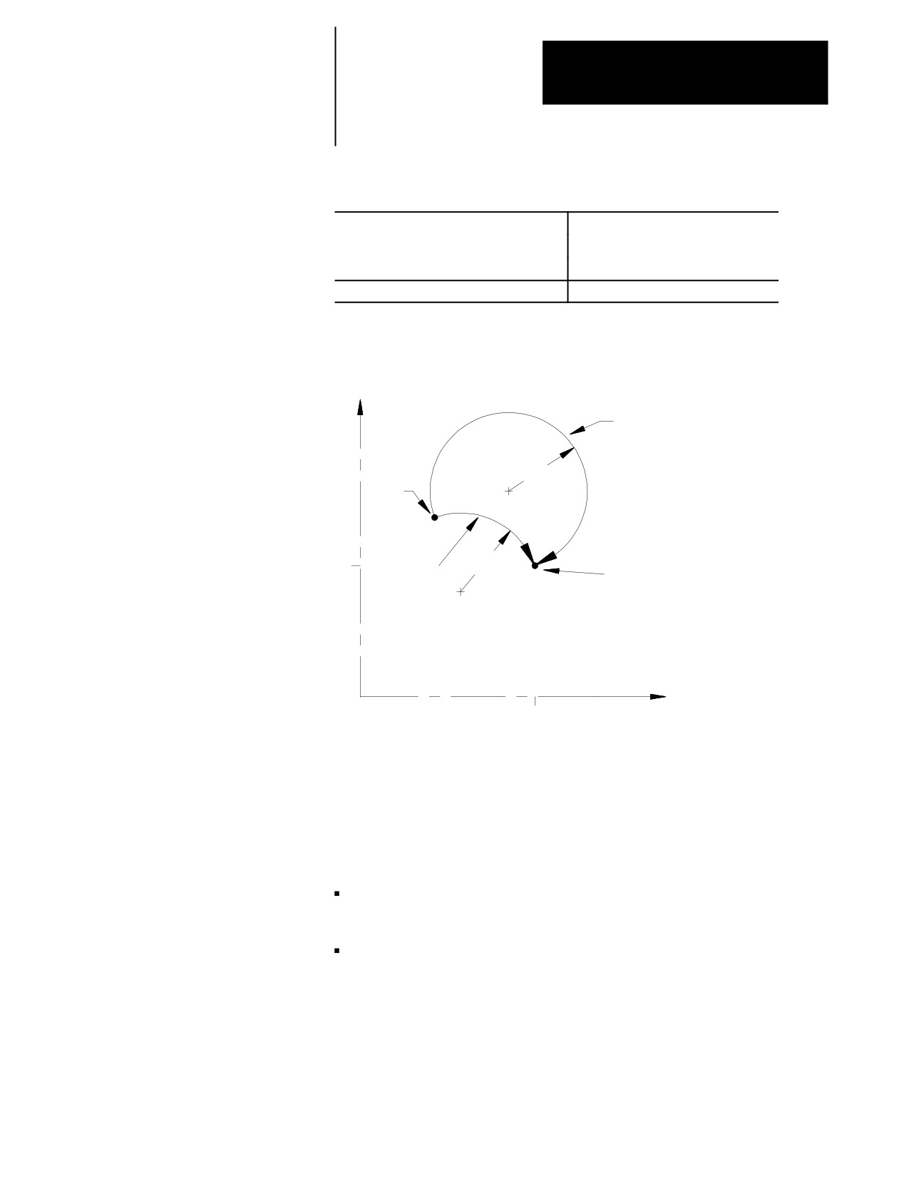
When you program an arc using the radius (R) value, two arcs are possible
(Figure 14.5). Program the R-word with a positive or negative value to
distinguish between these arcs.
14-6
Chapter 14
Axis Motion
Example 14.5
Arc Programmed Using Radius
Arc 1
Arc 2
center angle less than
center angle greater than
180 degrees
180 degrees
G90G02X25.Z40.R18.F.1;
G90G02X25.Z40.R-18.F.1;
Figure 14.5
Results of An Arc Programmed with Radius Command, Example 14.5
X
Arc 2
start
R-18
point
25
Arc 1
R18
end point
Z
40
Important: Any axis that is not specified when programming a circle
remains at its current axis position value. This results in the arc’s end point
having the same coordinate value as the start point of the arc for that axis.
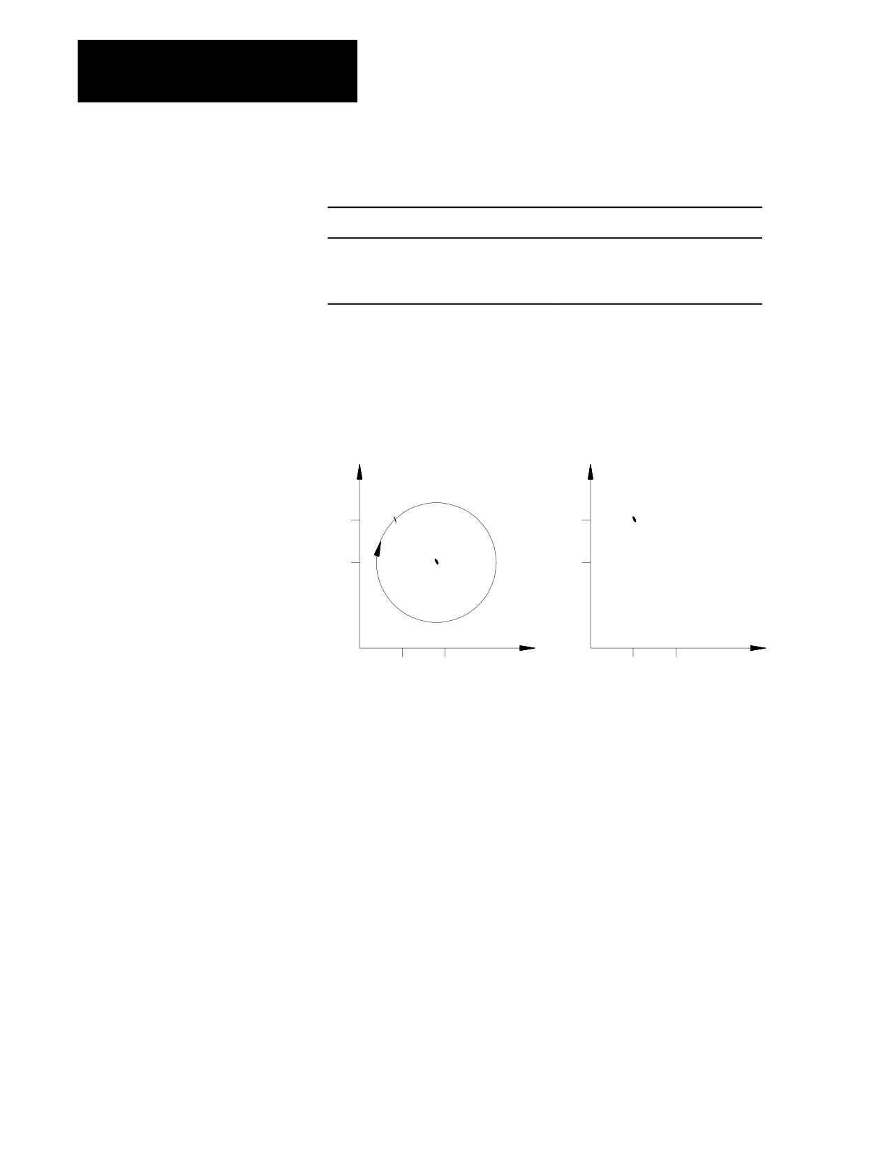
If you do not specify the end point of the arc, or if the end point is the same
as the start point, two results are possible:
if you use I and/or K to program the arc center, the control cuts a full
circle
if you use R to program the radius of the arc, no arc is made (the control
does not move either axis)
14-7
Chapter 14
Axis Motion
Example 14.6
Arc End Points Same As Start Points
Arc 1-Full Circle
Arc 2-No Motion
G02I-5.K5.F.1;
G02R7.07F.1;
or
or
G02X15.Z5.I-5.K5.F.1;
G02X15.Z5.R7.07F.1;
Figure 14.6
Results of An Arc with End Point Equal To Start Point, Example 14.6
Arc 1
Arc 2
Full circle
0 degree center angle arc
(no axis motion)
X
X
start
start
15
15
end
end
10
10
Center defined
Center defined by R
by I and J
Z
Z
5
10
5
10
If you program a radius command, R, in the same block as I, and/or K, the
control gives the R priority. The I-, and/or K-words are then ignored.
Important: Your system installer can specify the maximum allowed
difference between the starting radius of the arc and the ending radius of
the arc. If the difference exceeds the allowed value set in AMP, an error
occurs.
14-8
Chapter 14
Axis Motion
14.1.4
This section describes how to program a rotary axis. A rotary axis is a
non-linear axis that typically rotates about a fixed point. A rotary axis is
Positioning Rotary Axes
not the same as a spindle which uses an M19 to orient to a specific angle.
A spindle orient (M19) cannot move simultaneously with the other axes in
the system. A rotary axis is capable of rotating when other axes are being
moved.
Your system installer must determine which axes are rotary axes or linear
axes, in AMP. Your system installer also determines in AMP the address
that is used to command a rotary axis. This manual assumes that the
C-word is used to program a rotary axis. Refer to your system installer’s
documentation for the rotary axis words used in a specific system.
A rotary axis is programmed in degrees. This manual assumes that your
system installer has configured the rotary axis to “roll over” at 359.99°.
After the rotary axis exceeds 359.99°of rotation, its position display rolls
over to 0°and starts increasing. If the axis rotates to a position less than
0°, its position display rolls over to 359.99°and starts decreasing.
Typically a rotary axis is programmed in a block by itself or with linear
moves (rapid G00 or cutting G01 moves). You can program a rotary axis
in a block that contains circular moves (G02 or G03).
Programming in absolute or incremental
You can program rotary axes in absolute or incremental mode.
In absolute mode (G90), the rotary axis is programmed to angular
positions. These positions are programmed between 0°and 359.99°. The
sign given to this angular position determines the direction that the rotary
axis travels to reach the programmed angle. For example, programming:
G90C25;
in a part program causes the rotary axis C, to rotate to an angle of 25°
(referenced from a position 0 determined by your system installer) and
rotate the axis in the positive direction to reach this position.
Programming:
G90C-25;
in a part program causes the rotary axis C, to rotate to an angle of 25°and
rotate the axis in the negative direction to reach this position.
14-9
Chapter 14
Axis Motion
In incremental mode (G91), the rotary axis is programmed to move in an
angular distance (not to a specified angle as in absolute). The maximum
incremental departure depends on the programming format selected in
AMP by your system installer. The sign of the angle determines what
direction the rotary axis rotates. For example, if the current C axis position
is 25°and this block is programmed:
G91C50;
the C axis would rotate 50°in the positive direction. The new C axis
position would be 75°.
If the current C axis position is 25°and this block is programmed:
G91C-50;
the C axis would rotate 50°in the negative direction. The new C axis
position would be 335°.
In this mode:
you:
incremental (G91)
program a value greater than the rollover amount results in the rotary
axis making one or more complete revolutions.
absolute (G90)
cannot program a rotary axis move greater than the rollover amount.
circular interpolation
cannot program a rotary axis move unless these conditions are met::
(G02 or G03)
· the rotary axis cannot be in the active plane
· the rotary axis must be programmed in the same block as a valid
circular move made with the axes in the active plane
Important: You can program the largest move with a rotary axis is equal
to the rollover amount. Any attempt to program a move that generates
more motion than the rollover amount is truncated and moved to the
position that has the same numerical endpoint as the programmed position.
For example if this incremental move is programmed from a position of
10°:
G91C370;
the actual endpoint of the above move is still 20°; however, the rotary axis
did not get there by revolving one revolution. Instead, it positioned itself
directly to 20°without passing 20 once as expected.
14-10
Chapter 14
Axis Motion
Determining Rotary Axis Feedrates
The feedrate for a rotary axis is determined in much the same way as linear
axes.
When the control is in rapid mode (G00), the feedrate for the rotary axis is
the rapid feedrate for that axis as set in AMP. Remember that if other axes
are moving in the same block, the feedrate for the block is limited by the
axis that takes the longest time to complete its programmed move at its
rapid speed. (see chapter 18 for details).
When the control is in one of the cutting modes (G01, G02, or G03), the
control uses the programmed feedrate to calculate the angular velocity of
the rotary axis. This feedrate is still limited to the maximum cutting
feedrate (feedrate clamp) as determined in AMP.
When you program in this mode:
The rotary feedrate units are in:
G94 feed per minute
degrees per minute.
G95 feed per revolution
degrees per revolution of the spindle.
In any event, if a rotary axis is programmed in a block with other axis
moves in either rapid (G00) or cutting (G01, G02, or G03) modes, all axes
reach their destinations at the same instant.
CAUTION: When programming a rotary axis remember that
the programmed feedrate is in units of angular velocity. This
means that the actual cutting feedrate depends on the tools
distance from the center of rotation of the rotary axis.
14.1.5
Your system installer has the option of controlling selected axes through
the PAL program. When an axis is under PAL control, the operator and
PAL Axis Mover
part program have no control on that axis. Jog commands, as well as part
program commands, are typically ignored unless PAL has been written to
manipulate these values in some manner.
Be aware that it is possible to disable axis position displays on the CRT for
an axis under PAL control. Refer to the documentation provided by your
system installer for details on an axis controlled by PAL.
Important: S--Curve Acc/Dec mode is not available with PAL Axis
Mover.
14-11
Chapter 14
Axis Motion
14.2
Machine tools have a fixed machine home position that is used to establish
the coordinate systems. The 9/Series control offers two methods for
Automatic Motion To and
homing a machine after power up.
From Machine Home
Operation:
Description:
Manual machine home
uses switches or buttons on the MTB panel provided solely for this
purpose. Manual homing is described in detail in chapter 4.
Automatic machine home
uses a programmed machine home code.
14.2.1
You accomplish automatic homing by the using a G28 code. When
Automatic Machine Homing
programmed as the first motion block in a part program, (or through MDI)
a G28 automatically homes any axes programmed in the G28 block that
(G28)
have not yet been homed. Only axes that have their axis words
programmed in the G28 block are homed.
Homing follows the sequence of homing events described in chapter 4.
The coordinate values that are programmed with the axis words in a G28
block are stored by the control as intermediate point values (described in
the next section).
If all the axes programmed in the G28 block have already been homed
when the G28 code is executed, then the control considers it an “Automatic
Return to Machine Home” as described in the next section.
Important: When a homing request is made the feedback device for the
axis (typically an encoder) must encounter at least one marker before
tripping the homing limit switch. If the axis is close to the home limit
switch you should jog the axis away from this switch before attempting a
homing operation.
Automatic Machine Homing (G28) with Distance Coded Markers
The following outlines automatic machine homing (G28) for an axis with
DCM feedback if the axis has not already been homed:
1.
The axis moves at a speed and direction defined in AMP by G28
Home Speed and G28 Direction to Home, respectively.
The axis will come to a stop once the axis crosses three consecutive
markers on the DCM scale.
Important: To determine an absolute position using DCMs, you must
encounter at least three consecutive markers. Thus, if the axis position will
not accommodate this assumption, the axis must be moved to another
position before attempting a homing operation.
14-12
Chapter 14
Axis Motion
2.
When the output command equals 0 (i.e., the axis stops), the control
will determine the absolute position. Refer to your AMP manual for
more information about DCM Homing for Absolute Position.
If your axis is already homed, refer to the Automatic Return to
Home (G28) section later in this chapter.
Important: DCM axis homing must be performed manually or by
programming a G28. Attempting to program any motion command other
than a G28 will result in the decode error “MUST HOME AXIS”.
14.2.2
When a G28 is executed in a part program (or through MDI) after the axes
Automatic Return to
have already been homed, it causes a return to machine home. In this case,
the axes specified in the G28 block simply go to their respective home
Machine Home (G28)
positions in the machine coordinate system after moving to a programmed
intermediate point. They do not repeat the homing routine of moving to
the limit switches and searching for the encoder marker. For example,
executing the block:
G28 X__ Z__;
in either absolute or incremental mode would return the axes automatically
to the machine home via an intermediate point. The control stores the
intermediate point specified by the axis words (X, Z) in memory to be used
as the point of return for the automatic return from machine home
operation called out by G29.
The return operation generates two axis moves both executed at the rapid
feedrate. The first move is to the intermediate point, and the second is to
the axis home position.
Although this command moves the axes at rapid feedrate as if in G00
mode, it is not modal. If G01, G02, or G03 modes are active, they are only
temporarily canceled for the return to home moves.
Only the axes specified in the G28 block are returned to home. For
example:
N1 G28 X4.0;
(X axis is moved to home after moving to 4.0)
N2 G28 X4.0 Z2.0;
(X and Z axes are moved to home after moving to
(4.0, 2.0))
14-13
Chapter 14
Axis Motion
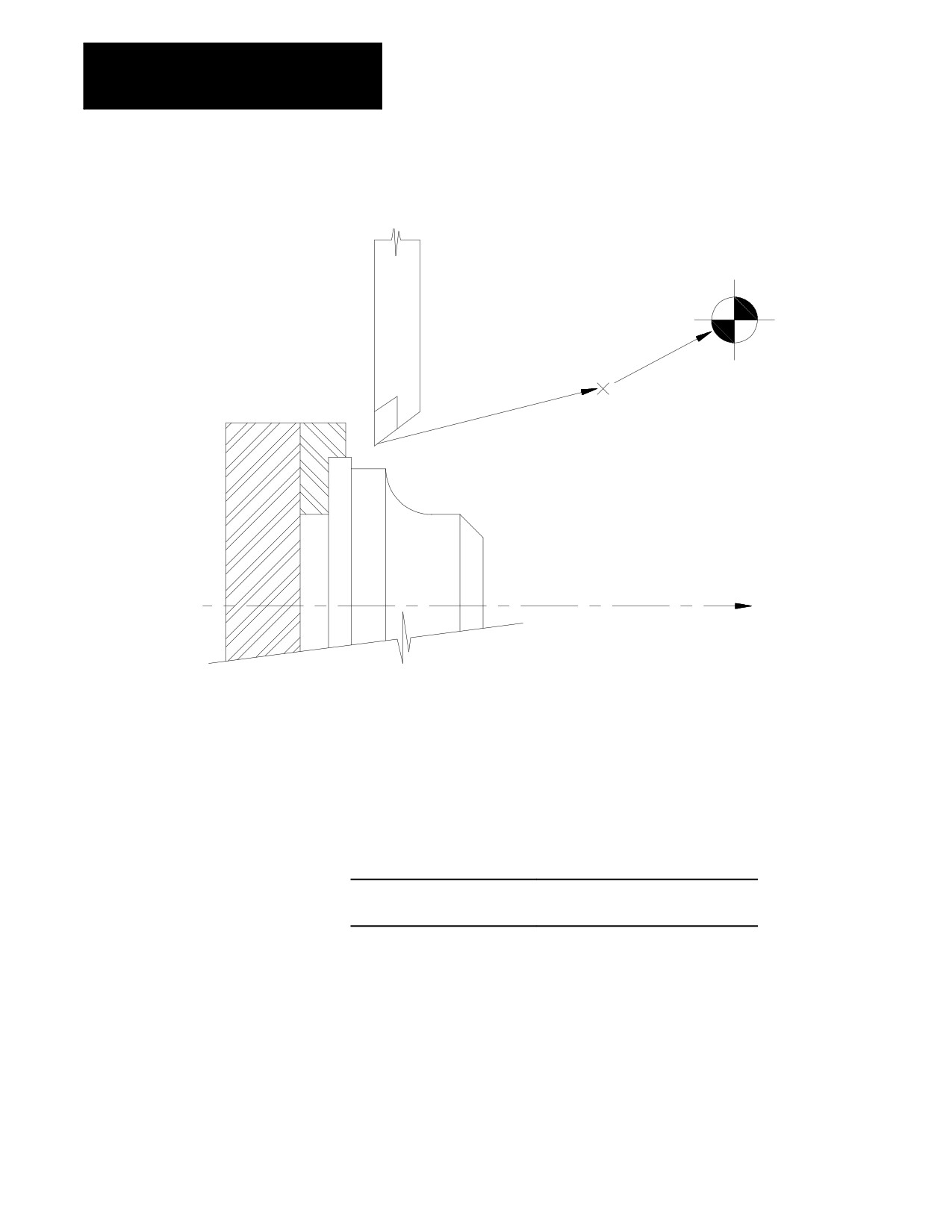
Figure 14.7
Automatic Return to Machine Home (G28)
Machine home
Intermediate point
Z
Usually a G28 is followed by a G29 (automatic return from machine
home) in a part program; however, the control stores the intermediate point
in memory for use with any subsequent G29 block executed before power
down. Only one intermediate point is stored for each axis. When a G28 is
programmed with a new intermediate point, any axis not programmed in
that block remains at the old value.
For example:
N1 G28 X4.0 Z3.0;
Intermediate point X=4 Z=3
N2 G28 Z2.0;
New intermediate point X=4, Z=2
Important: When the control executes a G28 or G30 block it temporarily
removes any tool offsets and cutter compensation during the axis move to
the intermediate point. The offsets and/or cutter compensation are
automatically re-activated during the first block containing axis motion
following the G28 or G30, unless that block is a G29 block. If a G29
follows, the offsets and/or cutter compensation remain deactivated on the
way to the intermediate point and are re-activated when the axis moves
from the intermediate point back to the point indicated in the G29 block.
14-14

Chapter 14
Axis Motion
14.2.3
When a G29 is executed in a part program (or through MDI), the axis or
axes move first to the intermediate point, and then to the position indicated
Automatic Return from
in the G29 block. If a G28 was just executed, then this has the effect of
Machine Home (G29)
returning the axis from machine home.
For example, executing the block:
G29 X7.0 Z1.5;
in absolute mode would move the axes to (7.0, 1.5) after passing through
the intermediate point stored in control memory. In incremental mode, this
block would move the axes to a position that is X7.0 and Z1.5 units away
from the home point.
The intermediate point is stored in control memory after a G28 return to
machine home or a G30 move to alternate home is executed. A G29 block
is usually executed after a G28 or G30 block, typically to return the cutting
tool to the part after a tool change.
Although this command moves the axes at rapid feedrate as if in G00
mode, it is not modal. If G01, G02, or G03 modes are active, they are
temporarily canceled for the return from home moves.
Only the axes specified in the G29 block are moved. For example:
N1 G28 X5.0 Z1.0;
(X and Z axes are moved to home after moving to X=5.0
Z=1.0)
N2 G29 X3.;
(X moves to X=5.0 then to X=3.0 -- -- -- Z does not move)
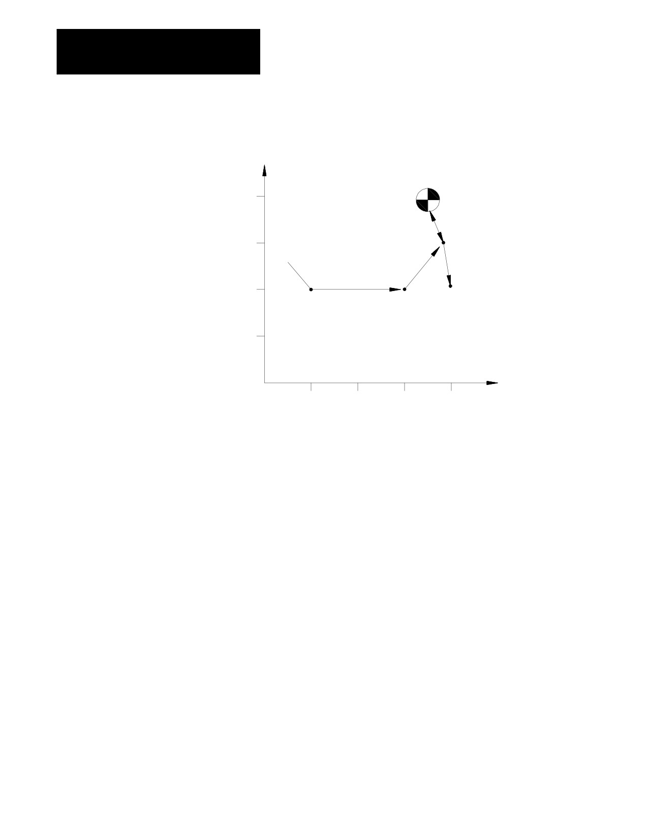
Example 14.7
Automatic Return From Machine Home
N00010
X100.Z50.;
N00020
Z150.;
N00030
G28X150.Z180.;
N00040
G29X200.Z100.;
14-15
Chapter 14
Axis Motion
Figure 14.8
Automatic Return From Machine Home, Results of Example 14.7
X
Machine home
200
N30
150
N40
N30
N10
N20
100
50
Z
50
100
150
200
Important: When a G29 is executed, tool offsets and/or cutter
compensation are deactivated on the way to the intermediate point, and
they are re-activated when the axis moves from the intermediate point back
to the point indicated in the G29 block.
14.2.4
A G27 causes the control to move the axes at rapid directly to the machine
Machine Home Return
home position. Only the axes included in the G27 block are moved.
Check (G27)
G27 X__ Z__;
The value entered with the axis name in the G27 block must be the
machine home coordinate for that axis. If it is not, no axis motion takes
place and the control issues the error message:
“INVALID ENDPOINT IN G27 BLOCK”
Aside from this endpoint check, the only difference between a G27 block
and a G00 block requesting a move to the machine home coordinates is
that the G27 is not modal. If G01, G02, or G03 modes were active before
the G27 was executed, they are reactivated immediately after the G27
block is completed.
G27 block commands are usually given after tool offset modes have been
cancelled.
14-16
Chapter 14
Axis Motion
If an attempt is made to execute a G27 before the axes have been homed,
the control goes to cycle stop and displays this error message:
“MACHINE HOME REQUIRED OR G28”
14.2.5
The G30 command is similar to the G28 command. The main difference is
the axis or axes move to an alternate home position instead of machine
Move To Alternate Home
home. The command format determines whether the axes return to a
(G30)
second, third, or fourth alternate home position. Any axis programmed in
the G30 block must have been homed prior to G30 execution.
The alternate home positions are defined for each axis in AMP by your
system installer.
To use the G30 command follow this format:
G30 X__ Z__;
or
(second alternate home position)
G30 P2 X__ Z__;
G30 P3 X__ Z__;
(third alternate home position)
G30 P4 X__ Z__;
(fourth alternate home position)
The axis words in the above block establish the intermediate point in the
same manner as the G28 code described on page 14-13. Axes move to the
intermediate point defined in the G30 block prior to moving to the
alternate home position. This intermediate point is the same intermediate
point as the one discussed with the G28 code. When intermediate values
are programmed in a G28 block, they replace G30 intermediate point
values and visa-versa. This intermediate point is used by the G29
automatic return code.
Only those axes included in the G30 block are sent to the alternate home
position.
A typical application for the G30 command would be if the automatic tool
changer were located at a position other than machine home.
If an axis included in the G30 block has not been homed, block execution
stops and this error message appears:
“MACHINE HOME REQUIRED OR G28”
14-17
Chapter 14
Axis Motion
Important: When the control executes a G28 or G30 block, it temporarily
removes any tool offsets and cutter compensation during the axis move to
the intermediate point. The offsets and/or cutter compensation are
automatically re-activated during the first block containing axis motion
following the G28 or G30, unless that block is a G29 block. If a G29
follows, the offsets and/or cutter compensation remain deactivated on the
way to the intermediate point and are re-activated when the axis moves
from the intermediate point back to the point indicated in the G29 block.
14.3
The G04 command delays the execution of the next data block. Dwell
length is specified in either of two types.
Dwell (G04)
Seconds
Number of spindle revolutions
The type used is normally dependant on the feedrate mode (G94 or G95)
active at the time. The type can also be permanently fixed to “seconds”
regardless of G94 or G95 mode, by setting the proper AMP parameter.
Dwell is not possible in the G93 inverse time feed mode.
14.3.1
In the G94 mode (feed per minute) G04 suspends execution of the
Dwell - Seconds
commands in the next block for a programmed length of time in seconds.
G94G04
P__;
X__;
U__;
Specify the required dwell time by either a P-, X-, or U-word in units of
seconds. It does not matter which of these three words you use, as long as
only one appears in the same block. The allowable dwell time is 0.001 -
99999.999 seconds.
When you program a dwell in seconds you system installer has the option
of writing PAL to allow a portion of the dwell to be skipped. If this feature
is used, when the appropriate signal is sent to PAL (from a switch or other
device) the control automatically skips any portion of the dwell that has
not been executed and proceeds to the next block in the program. The axes
positions when the skip signal is sent to PAL is recorded and stored as
system parameters #5071 - #5076. See specifics on the G31 skip cycles for
details.
14-18
Chapter 14
Axis Motion
14.3.2
In the G95 mode (feed per revolution), G04 suspends execution of
commands in the next block for the time it takes the controlling spindle to
Dwell - Number of Spindle
turn a designated number of revolutions.
Revolutions
G95G04
P__;
X__;
U__;
Specify the required dwell length by either a P-, X-, or U-word in units of
spindle revolutions. It does not matter which of these three words you use,
as long as only one appears in the same block. The allowable range is
0.001 - 99999.999 revolutions.
14.4
There are two types of mirroring. They are:
Mirror Image (G50.1, G51.1)
Mirror image:
Activate through:
programmable
programming a G50.1 and G51.1
manual
PAL or the {FRONT PANEL} softkey
Programmable Mirror Image (G50.1, G51.1)
Use the programmable mirror image feature to mirror (duplicate yet
reversed) axis motion commands about some defined plane. Activate this
feature using the G51.1 code. Cancel it using the G50.1 code. Mirroring
takes place about the axis position specified in the G51.1 code.
The format for the G51.1 code is:
G51.1X__ Z__ ;
The axis motion commands in any following blocks are executed with the
motion direction reversed (including incremental moves) as if a mirror
were placed on the designated point parallel with the axis. The G51.1 code
is modal and remains in effect until cancelled by a G50.1 command.
Use the axis word programmed with the G51.1 command to define the
mirroring location. The defined location intercepts the programmed axis at
the programmed position. If only one axis is programmed, the mirroring
plane is perpendicular to that axis. If more than one axis is programmed,
the mirror plane passes through these points.
Important: The control mirrors only those axes that are programmed out
in the G51.1 block. Axes not programmed in the G51.1 block execute
normally.
A G50.1 block cancels the mirror image function.
G50.1X__ Z__ ;
14-19
Chapter 14
Axis Motion
The control only cancels the mirror feature for those axes that are
programmed in the G50.1 block. Axes not programmed in the G50.1 block
remain mirrored. There is no significance to the values programmed with
the axis words in a G50.1 block. Axis values might not be required,
depending on how the way AMP was configured by your system installer.
In either case, the control ignores these values.
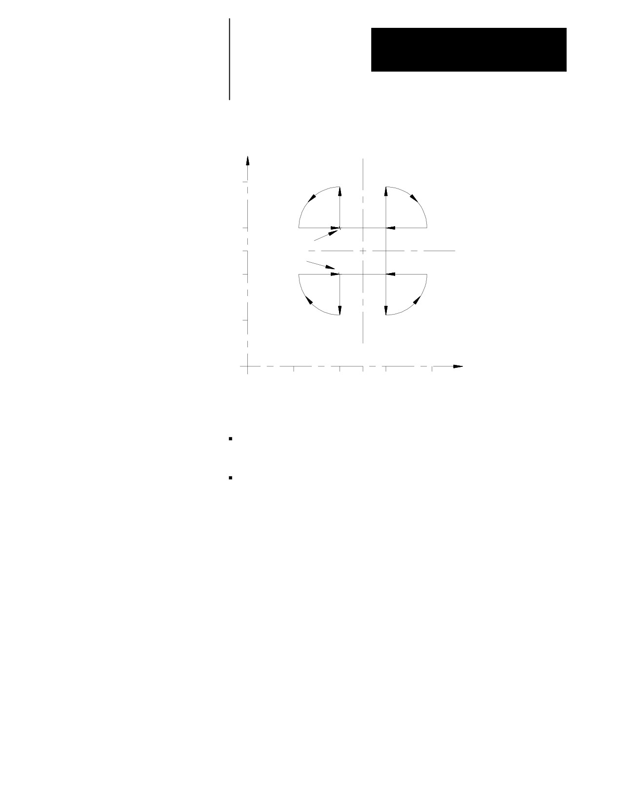
Example 14.8
Programmable Mirror Image
Main Program
Comment
(Mirror);
comment block, main program
G00G90;
rapid positioning, absolute mode
M98P8500;
call subprogram 8500
G51.1Z75.;
mirror active on X
M98P8500;
call subprogram 8500
G51.1X75.;
mirror active on Z (and X)
M98P8500;
call subprogram 8500
G50.1Z0;
cancel mirror on Z (active on X only)
M98P8500;
call subprogram 8500
G50.1X0;
cancel mirror on X (no mirroring)
M30;
Subprogram
Comment
O8500;
program number
G00G90Z60.X90.;
rapid to start point
G01X120.F.1;
move 1
G03Z30.X90.R30;
move 2
G01Z60.;
move 3
M99;
return from subprogram
14-20
Chapter 14
Axis Motion
Figure 14.9
Programmable Mirror Image, Results of Example 14.8
X
120
90
Start point
75
End point
60
30
Z
0
30
60
75
90
120
When the mirror image function is active on only one of a pair of axes, the
control:
executes a reverse of programmed G02/G03 arcs. G02 becomes
counterclockwise and G03 becomes clockwise
activates a reverse of programmed G41/G42 cutter compensation. G41
becomes tool right and G42 becomes tool left
Manual Mirror Image
In addition to the programmable mirror image feature, the control can also
be equipped with an optional mirror image switch, installed by your
system installer that activates the manual mirror image feature. This
feature can also be activated by using the {FRONT PANEL} softkey.
The manual mirror image feature differs from the programmable mirror
image feature. When you use manual mirror image, the location of the
mirrored plane is fixed along the selected axis in the current work
coordinate system. This means that the mirror plane is parallel to the
selected axis. It passes through the zero point of the currently active work
coordinate system.
The mirrored plane is fixed and cannot be moved from along the selected
axis. This mirrored plane is the equivalent of programming a
programmable mirror image and using all zero values for the axis words.
14-21
Chapter 14
Axis Motion
Your system installer can install a switch for each of the 4 available axes.
What axes are mirrored with what switches depends on the PAL program
in your system. You can mirror about more then one axis using more then
one manual mirror image switch at the same time or one switch can control
more than one axis. Refer to documentation prepared by your system
installer for details.
Important: You can use programmable mirror image at the same time as
manual mirror image. The programmable mirror image is done first,
followed by the manual mirror image. The same axis can be mirrored by
programmable and manual mirror image at the same time.
14.5
Use this feature to disable the axis position display and allow an axis to be
Axis Clamp
clamped into position. Typically an axis clamp is performed by the
execution of an M-code in a part program or by a switch of some type
controlled by the operator. Your system installer determines how the axis
clamp feature is enabled in PAL. Refer to your system installer’s
documentation for details.
When an axis is clamped, the control freezes the axis position displays at
their position. Any drift or movement generated by some external force
does not generate any corrective response from the axis servo. This
prevents the servo from trying to move an axis back into position when it
has been mechanically clamped so it cannot move.
Any movement of the axis when it is clamped is added to the current value
of the following error. You can view this on the screen displaying
following error. Refer to the Integration manual. If the following axis
error exceeds its allowable maximum following error (set in AMP), an
error is generated and the control goes into E-Stop.
When the axis is unclamped, the control position display is reactivated and
the servo returns the axis to the necessary position for zero following error.
END OF CHAPTER
14-22
Chapter
15
Using QuickPath Plus‰
15.0
The QuickPath Plus feature offers a convenient programming method to
simplify programming with the 9/Series control.
Chapter Overview
We discuss some QuickPath Plus features in this chapter. Major topics
include:
Topic:
On page:
Programming
15-2
Linear QuickPath
15-3
Circular QuickPath
15-7
This method of programming can prove useful in simplifying the
programming of a part directly from a part drawing.
The most significant advantage to the QuickPath Plus feature is the
programmer no longer has the need to calculate the endpoint of every
block or every point of intersection. QuickPath Plus determines these
points from angles and lengths.
QuickPath Plus uses these addresses:
,A
Angle
This word is used to define the angle of a tool path. This manual
assumes that the ,A-word is used. The angle is always measured
counterclockwise from the first axis defining the currently active
plane. The angle is in units of degrees.
L
Length
This word is used to define the length of a linear tool path, the
direction of which is determined by the angle (,A). It is always
interpreted as an incremental value.
The 9/Series control offers a variety of sample patterns with prompting to
aid in the programming of QuickPath Plus. These are found under the
QuickView feature described in chapter 5.
15-1
Chapter 15
Using QuickPath Plus
15.1
When programming QuickPath Plus, remember:
Programming QuickPath
Any axis words that are programmed must be in the current plane, and
Plus
angles are measured from the first axis defining that plane. All
examples in this section assume that the ZX plane is active (angles are
measured relative to the Z axis).
QPP always uses “,A” as the angle word. When you create new
programs, always program the QPP angle with ,A. Your system
installer has the ability to define in AMP an additional letter that can
also be used for the QPP angle. Refer to your system installer’s
documentation. This additional QPP angle word is provided only for
program compatibility with older systems.
The angle word (,A) is always interpreted as an absolute angle,
regardless of the current mode (G90 or G91).
The L-word is always interpreted as an incremental distance from the
current position regardless of the current mode (G90 or G91). Radius or
diameter mode (G08 - G09) has no effect on the ,A- or L-word.
If you must program more than one block to perform the QuickPath
Plus operation being used, and an error is made in one of the program
blocks, the control always shows the error as being in the first block of
the two blocks, regardless of whether the error is in the first or the
second block. If programming in<SINGLE BLOCK> mode, the control
stops after the execution of the first block as normal.
If you must program more then one block to perform the QuickPath
Plus operation being used, a maximum of 4 non motion blocks can be
programmed between these blocks. A non motion block is any block
that does not generate axis motion on one of the two axis in the current
plane.
These G-codes cause a syntax error if programmed in any QuickPath
Plus block:
- All G-codes in G-code Group 0 (except G04, G09, and G60)
- All G-codes in G-code Group 1 (except G00, G01, G02, and
G03).
- All G-codes in G-code group 4, 6, 9, 10, 11, and 16.
The G-code table in appendix C lists the G-codes and their group numbers.
If you must program more then one block to perform a QuickPath Plus
operation, it causes an error if the current plane is changed to some
other parallel plane in between these blocks.
15-2
Chapter 15
Using QuickPath Plus
If an angle is programmed in a circular QuickPath Plus block, an error is
generated.
If an L-word is programmed in a G13, or G13.1 block an error is
generated.
15.2
One End Coordinate
Linear QuickPath Plus
Many times part drawings give a programmer only one axis dimension for
a tool path and require that the other axis dimension be calculated by the
angle. This QuickPath Plus feature eliminates the need for this calculation.
This must be a linear block. See section 15.3 for circular block.
The format for this block is:
,A__
X__
;
Z__
Where :
Is :
,A
Angle
This word is used to define the angle of a tool path. This manual
assumes that the ,A-word is used. The angle is a positive value when
measured counterclockwise from the first axis defining the currently active
plane and a negative value when measured clockwise. The angle is in
units of degrees.
X,Z End Point
This word is used to program one of the coordinates of the end point of a
linear path. The control calculates the other end point automatically. This
can be any axis word that is in the current plane.
Only one axes word from the current plane can be programmed in this
block. Any axis word that is not in the current plane is executed as a
normal linear move to that coordinate and combined with the QuickPath
Plus generated tool path. If both axis words from the current plane are
entered in the block, the angle is ignored and the control moves to the
coordinate position programmed with the axis words. All examples in this
section assume that the ZX plane is active.
Important: If the programmed tool path is going to be parallel to an axis
in the current plane, the axis word for the end point in the block should be
for the axis in the current plane that is not parallel to the tool path. This
means if the value of the angle (,A-word) is 0°or 180°, the second axis in
the plane must be programmed in the block. If the value of the angle is
90°or 270°, the first axis in the plane must be programmed in the block.
15-3
Chapter 15
Using QuickPath Plus
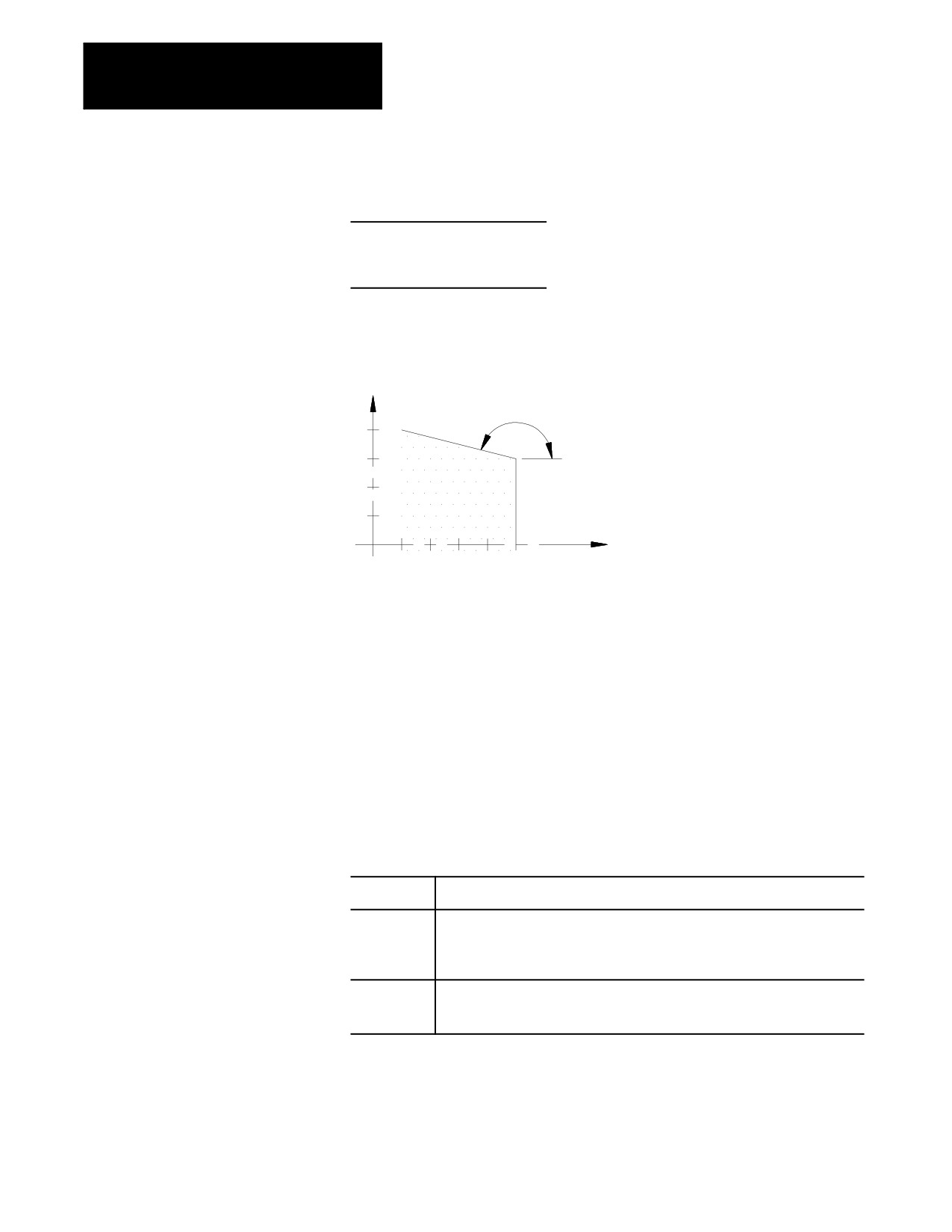
Example 15.1
Angle Designation:
N10 GO1 X0.0 Z25.0 F.1.;
N20 X15. ,A90;
N30 Z5.,A165;
Figure 15.1
Results of Angle Designation, Example 15.1
X
165°
15
10
5
Z
0
5
10
15
20
25
Important: Circular QuickPath Plus can also use an angle (,A) in a
program block. This is described in section 15.3.
No End Coordinate Known (L)
This feature of QuickPath Plus allows the programmer to define a tool path
using only the start point angle and length of a tool path. This must be a
linear block.
The format for this block is:
,A__ L__;
Where :
Is :
,A
Angle
This word is used to define the angle of a tool path. This manual assumes that
the ,A-word is used. The angle is a positive value when measured
counterclockwise from the first axis defining the currently active plane and a
negative value when measured clockwise. The angle is in units of degrees.
L Length
This word determines the length of the tool path. It is measured from the start
point to the end point of the move along a linear path. No coordinate points are
necessary.
15-4
Chapter 15
Using QuickPath Plus
Important: If any axis word from the current plane is designated in the
block, the L-word is ignored and the control calculates the end point from
the angle and the axis word. If an angle (,A) or a length (L) is
programmed in a block that also contains both axis words in the current
plane, then QuickPath Plus is not performed and the control ignores the ,A-
and the L-words in the block.
Example 15.2
Angle with Length Designation:
N10 GO1 X0. Z25. F.1.;
N20 ,A90 L15;
N30 ,A165 L20.7;
Figure 15.2
Results of Angle With Length Designation, Example 15.2
X
165°
15
10
5
Z
0
5
10
15
20
25
No Intersection Known
This feature of QuickPath Plus allows the programmer to define two
intersecting, consecutive, linear tool paths without knowing the point
where the actual intersection takes place. Both of these blocks must be
linear blocks and programmed in absolute mode. The angle of both of
these lines must be known.
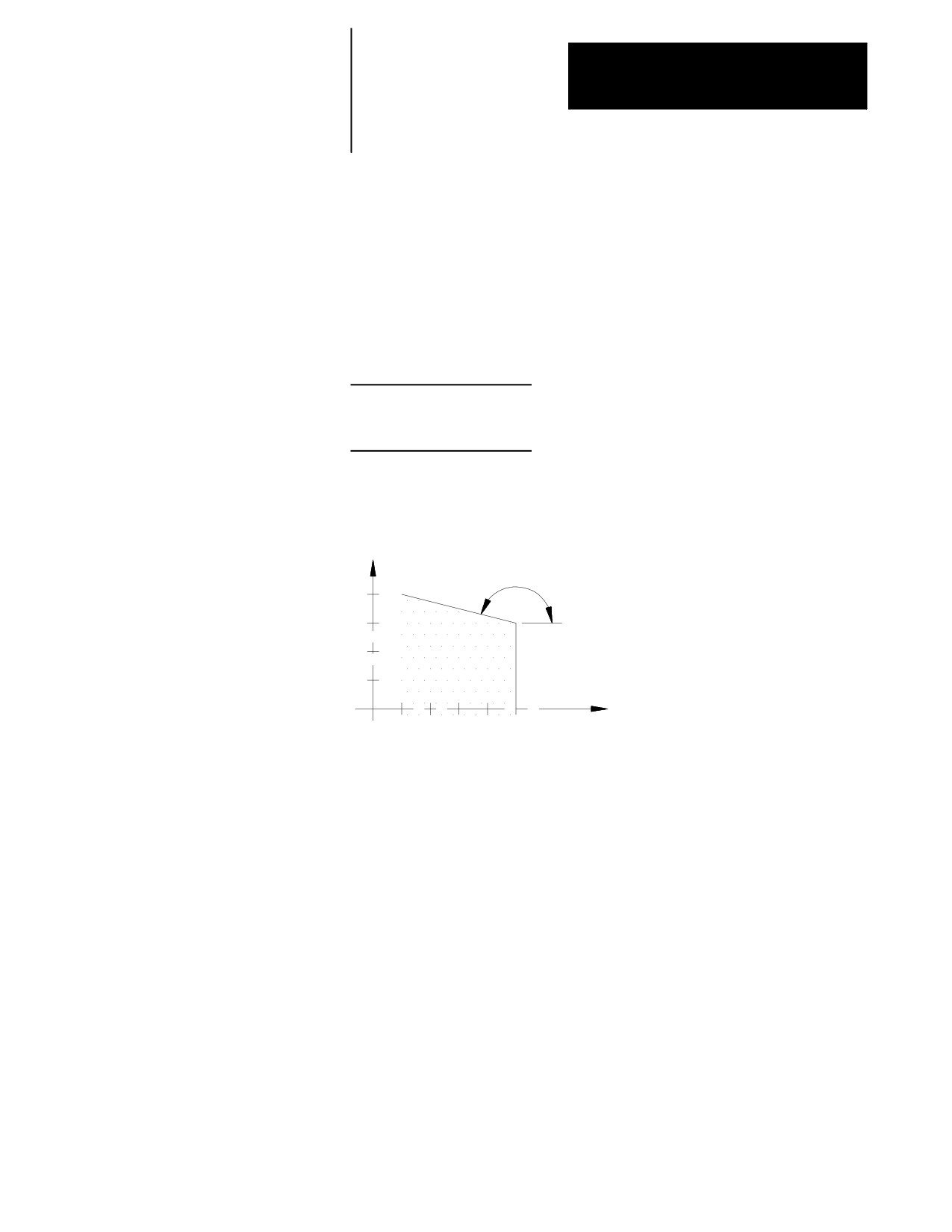
This is done with a sequence of two linear blocks (in the current plane) in
which QPP is used to calculated the end point of the first block. The start
point of the first block is the current tool position.
Important: The second block of these two blocks must be programmed in
absolute mode. Any attempt to program the second block in incremental
generates an error.
15-5
Chapter 15
Using QuickPath Plus
The format for these blocks is:
N1 ,A__;
N2 ,A__Z__X__;
Where :
Is :
,A
Angle
This word is used to define the angle of a tool path. This manual
assumes that the ,A-word is used. The angle is a positive value when
measured counterclockwise from the first axis defining the currently
active plane and a negative value when measured clockwise. The
angle is in units of degrees.
ZX End Point of
These represent the actual coordinate location of the end point of the
second block
second block. They must be programmed as absolute values and
must be axes in the current plane.
Important: There may be up to four program blocks between the two
blocks in the above format. The only requirement being that these blocks
may not generate axis motion in the current plane.
Both of these blocks must be programmed in the same plane. If the current
plane is changed between these two blocks execution, the control generates
an error.
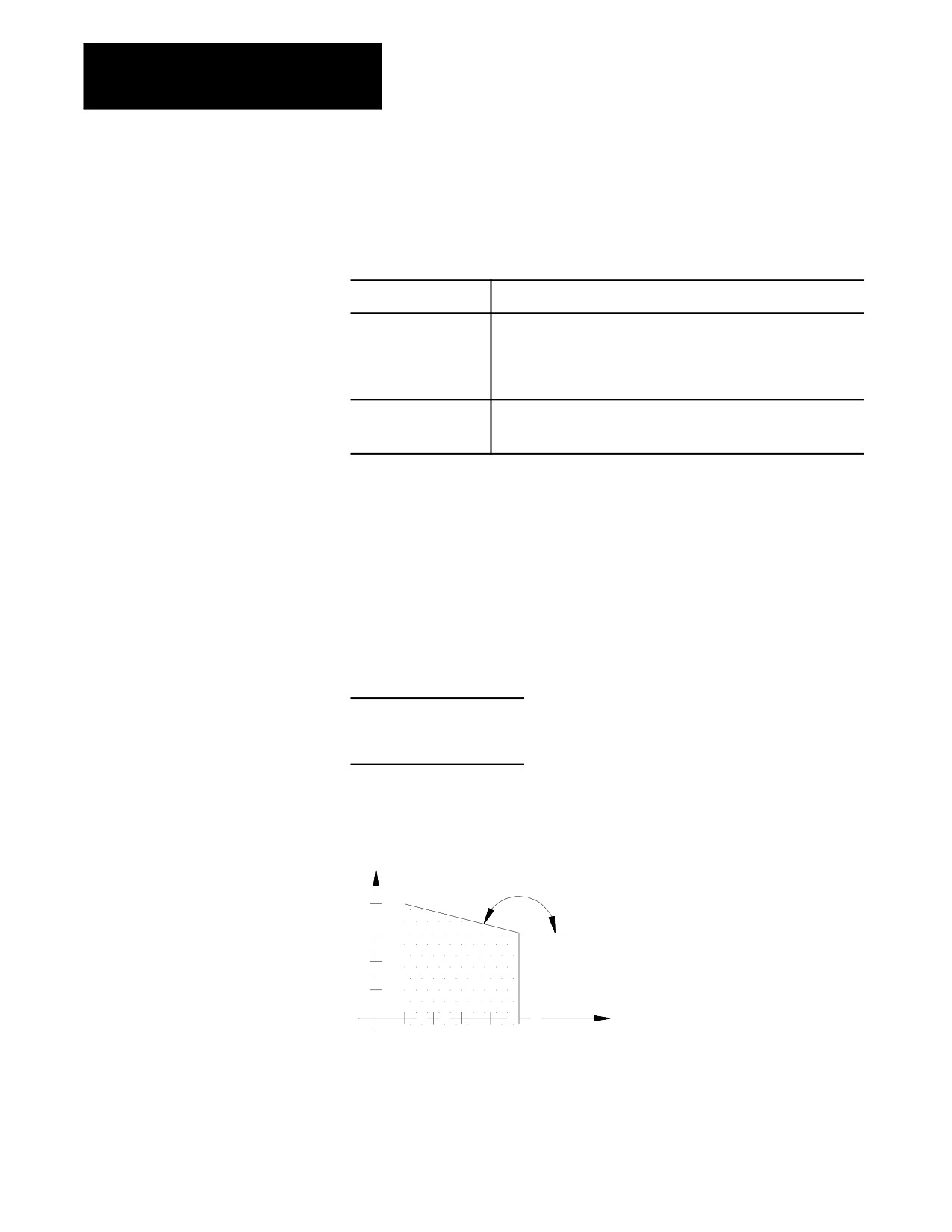
Example 15.3
QuickPath Plus When An Intersection is Unknown
N10 GO1 X0. Z25. F.1;
N20 ,A90;
N30 ,A165 X20.Z5.;
Figure 15.3
Results of Unknown Intersection, Example 15.3
X
165°
15
10
5
Z
0
5
10
15
20
25
If the control cannot determine an intersection point for the two linear
paths (for example, if the paths are parallel), an error occurs.
15-6
Chapter 15
Using QuickPath Plus
15.3
The programmer uses the Circular QuickPath when a drawing does not call
out the actual intersection of two consecutive tool paths and at least one of
Circular QuickPath Plus
the tool paths is circular. This prevents the programmer from having to do
(G13, G13.1)
any complex calculations to determine end points and start points when an
arc is involved.
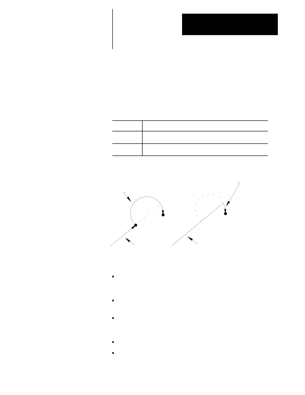
For most cases of circular QuickPath Plus there may be two possible
intersection points for the two defined blocks. Define which intersection is
desired using either G13 or G13.1 in the first of the two blocks.
Programming:
Defines:
G13
the first intersection that occurs when the tool path of the first block
intersects with the second block
G13.1
the second intersection that occurs when the tool path of the first block
intersects with the second block.
Figure 15.4
G13 vs G13.1 Intersections
Second block if G13.1 programmed
Second block if G13 programmed
1st block
1st block
When programming circular QuickPath Plus, remember:
When there is only one intersection involved with the tool paths, you
can program the G13 and G13.1 codes interchangeably. One of these
G-codes must be programmed however.
The G13 or G13.1 code must be programmed in the first of the two
blocks defining the two tool paths.
If the arc is programmed with an R-word, the two tool paths must be
tangent. The sign (+ or -) of the R-word determines the arc center
location as described in section 14.1.3.
The angle word (,A) cannot be programmed in a circular block.
Both absolute coordinate values in the current plane must be
programmed for the second block. Both must be programmed
regardless of whether the final coordinates change or not.
15-7
Chapter 15
Using QuickPath Plus
Linear to Circular blocks
When the coordinates of the intersection of a linear path into a circular
path are unknown, use the following format. G13 or G13.1 must be
programmed. These blocks must be programmed in absolute.
Format:
G13G01 ,A__;
or
G13G01 ,A__;
G02 Z__X__K__I__;
G02 Z__X__R__;
Important: If the second block is an arc and it is programmed by using I,
and K integrand, the values programmed with I, and K are not measured
from the start point of the arc as normally done. This is because the start
point of the arc is normally unknown when using this format. The
integrands specify the distance from the end point of the arc to the center
point.
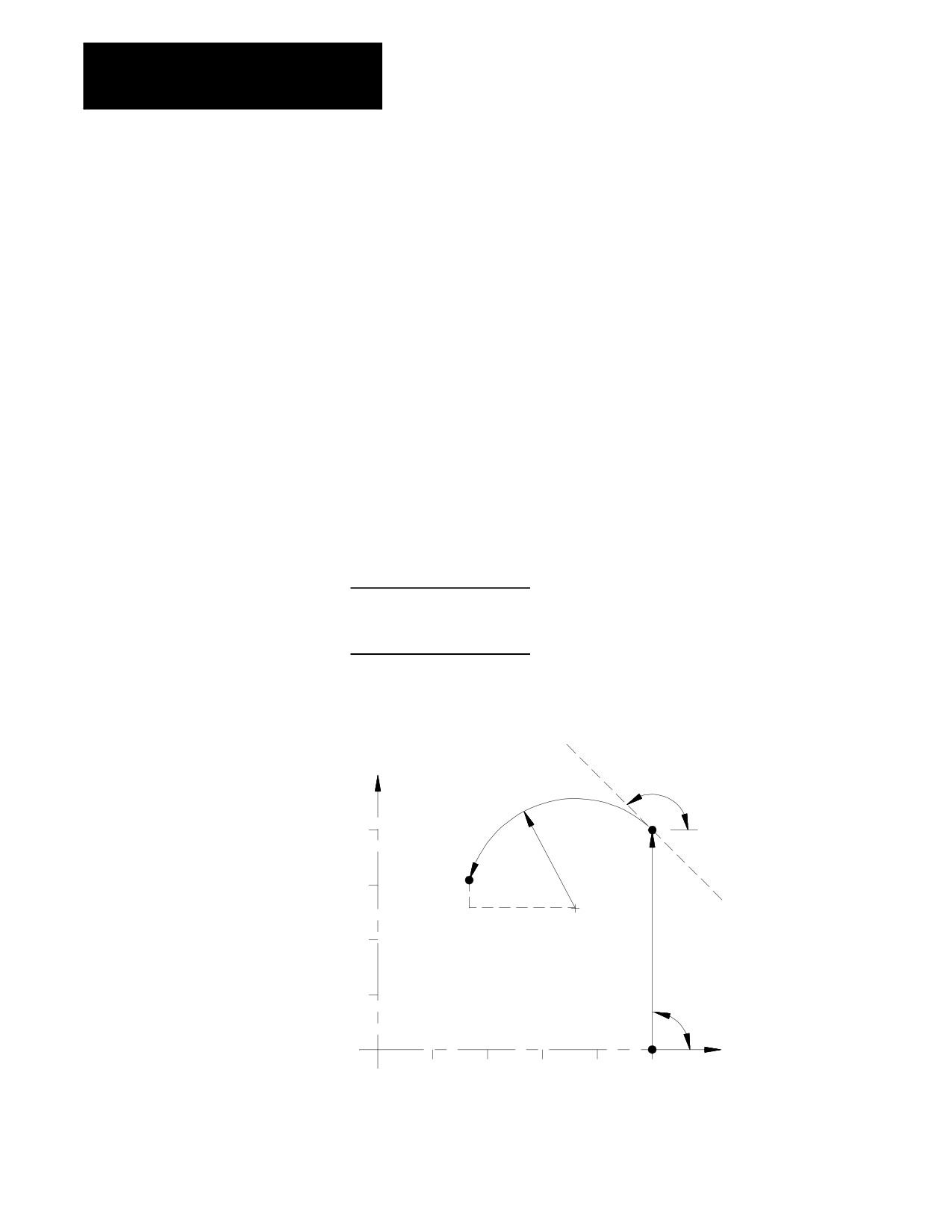
Example 15.4
Line Into Arc Without Programming Intersection
G00Z25.X0.;
G01G13.1,A90;
G03Z7.X15.K9.21I-2.;
Figure 15.5
Results Of Line into Arc Without Intersection, Example 15.4
X
135°
20
R 10.0
15
I
K
10
5
90°
Z
5
10
15
20
25
Important: You cannot program R to specify the arc radius for
linear-to-circular block combinations unless the two tool paths are tangent.
15-8
Chapter 15
Using QuickPath Plus
Circular to Linear blocks
When the coordinates of the intersection of a circular path into a linear
path are unknown, use the following format. G13 or G13.1 must be
programmed in the first of the two blocks. These blocks must be
programmed in absolute.
Format:
G13G02I__K_;
or
G13G02R__;
G01,A__Z__X__;
G01,A__Z__X__;
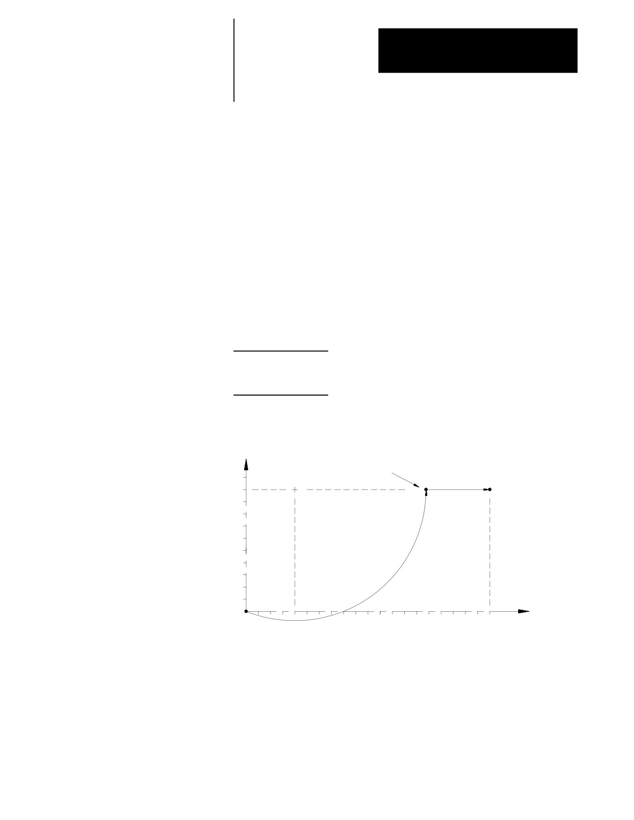
Important: K values are the normal integrand values when you use this
format (measured from start point of arc to arc center).
Example 15.5
Arc Into Line Without Programming Intersection Point
G0X0Z0.;
G13G03K4I10F.1;
G01,A0X10Z20;
Figure 15.6
Results of Arc Into Line Without Intersection, Example 15.5
X
Control generates
intersection
10
8
6
4
2
Z
8
10
12
14
16
18
20
2
6
4
Important: R cannot be programmed to specify the arc radius for linear to
circular block combinations unless the two tool paths are tangent.
15-9
Chapter 15
Using QuickPath Plus
Circular to Circular blocks
When the coordinates of the point of intersection of a circular path into a
circular path are unknown, use the following format. G13 or G13.1 must
be programmed. If using this format, the R-word cannot be used to
specify the radius of an arc in either of the circular blocks. These blocks
must be programmed in absolute.
Format:
G13G02K__I__;
G02 Z__X__K__I__;
Important: The I, K integrand vectors are not necessarily the same values
as discussed for normal circular interpolation when you use this QuickPath
Plus format. The integrands of the first circular block specify the distance
from the START point to the center of the circle. The integrands of the
second circular block specify the distance from the END point to the center
of the circle (this is the reverse of normal). At least one of these integrand
words must be programmed in each of the two circular blocks.
Neither circular block can contain an angle word (,A) when you use this
format.
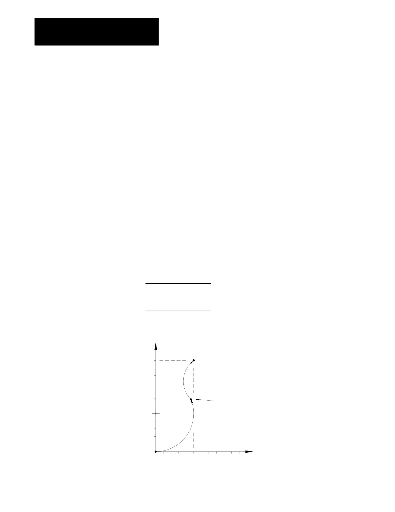
Example 15.6
Arc Into Arc Without Programming Intersection
G0X0.Z0.;
G13.G03I5F.1;
G02X12Z5I-2.75K2;
Figure 15.7
Results Arc Into Arc Without Intersection, Example 15.6
X
12
10
+
8
Control generates
6
intersection
4
2
Z
2
4
6
8
10
END OF CHAPTER
15-10