9/Series CNC Lathe. Operation and Programming Manual - page 23
Chapter 26
Drilling Cycles
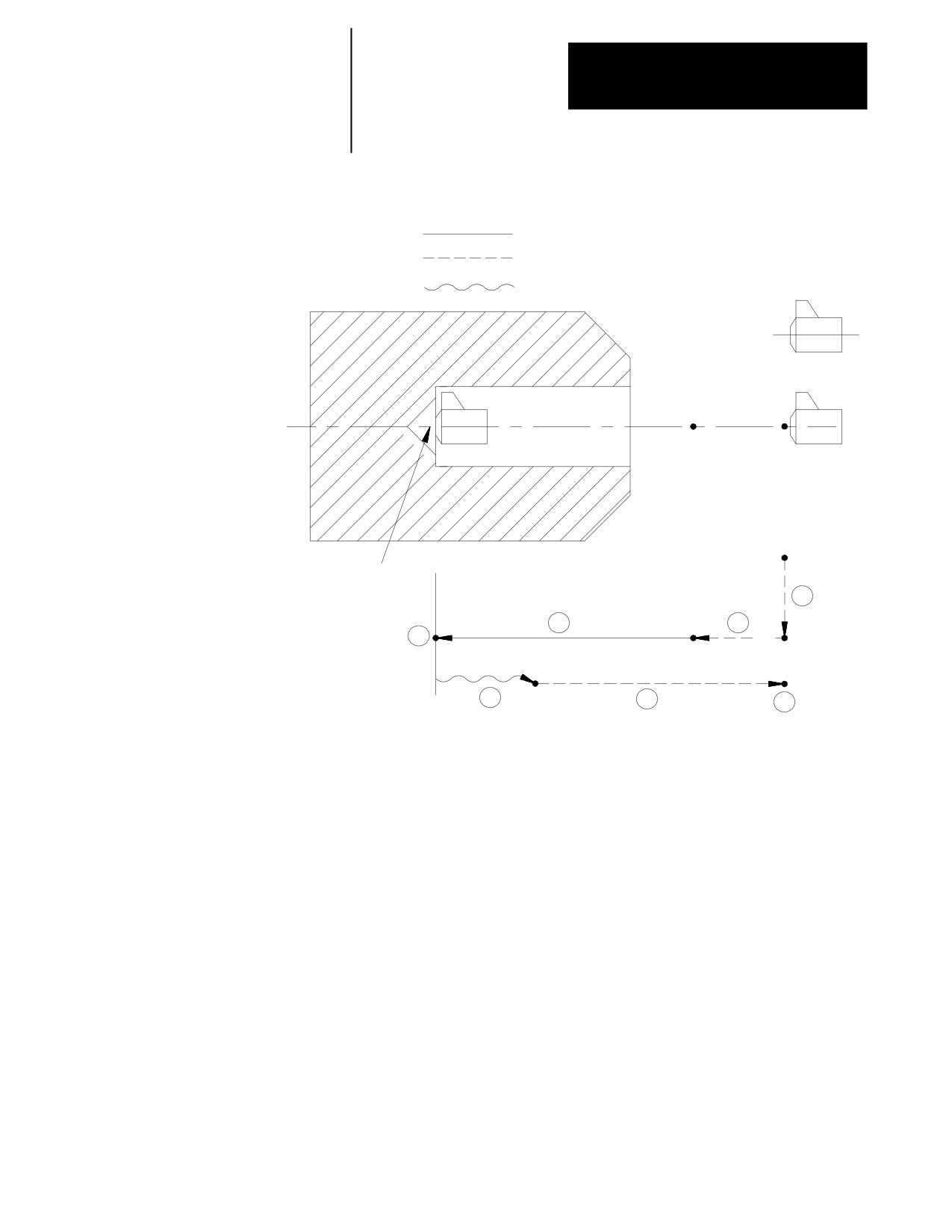
Figure 26.14
G88: Boring Cycle, Spindle Stop/Manually Out
Cutting feed
Rapid feed
Manual operation
R point level
Initial point
level
Hole bottom
1
3
2
Z
R
4
Spindle or live tool stops at
hole bottom after dwell
5
6
Cycle start
7
Spindle rotation in
the forward direction
In the G88 boring cycle, the control moves the axis in this manner:
1.
The tool rapids to the initial point level above the hole location.
2.
The boring tool then rapids to the R point level, slows to the
programmed cutting feedrate and begins the boring operation.
3.
The boring tool bores at the programmed feedrate until it reaches the
depth specified with the Z-word.
4.
If the user has entered a value for the P parameter, the boring tool
dwells after it reaches the bottom of the hole.
5.
After the tool reaches the Z depth, the spindle or live tool stops
revolving. At this point, the operator must perform a manual
retraction of the drilling axis as described in chapter 4.
(Press
<CYCLE START> to return the control to automatic mode.)
26-35

Chapter 26
Drilling Cycles
6.
The boring tool is then retracted at a rapid feedrate to initial point
level, as determined by G98.
7.
At this point, the rotation of the spindle or live tool changes to the
clockwise direction.
When the single block function is active, the control stops axis motion
after steps 1, 2 and 5.
(G89): Boring Cycle,
The operations in G89 are identical to as those of the G85 boring cycle
with the exception that the control executes a dwell at hole bottom.
Dwell/Feed Out
The format for the G89 cycle is:
G89X__Z__R__P__F__L__;
Where :
Is :
X
specifies location of the hole.
Z
defines the hole bottom.
R
defines the R point level.
P
defines the dwell period at hole bottom.
F
defines the cutting feedrate.
L
defines the number of times the drilling cycle is repeated.
See page 26-7 for a detailed description of these parameters.
Important: The programmer or operator must start spindle or live tool
rotation.
26-36
Chapter 26
Drilling Cycles
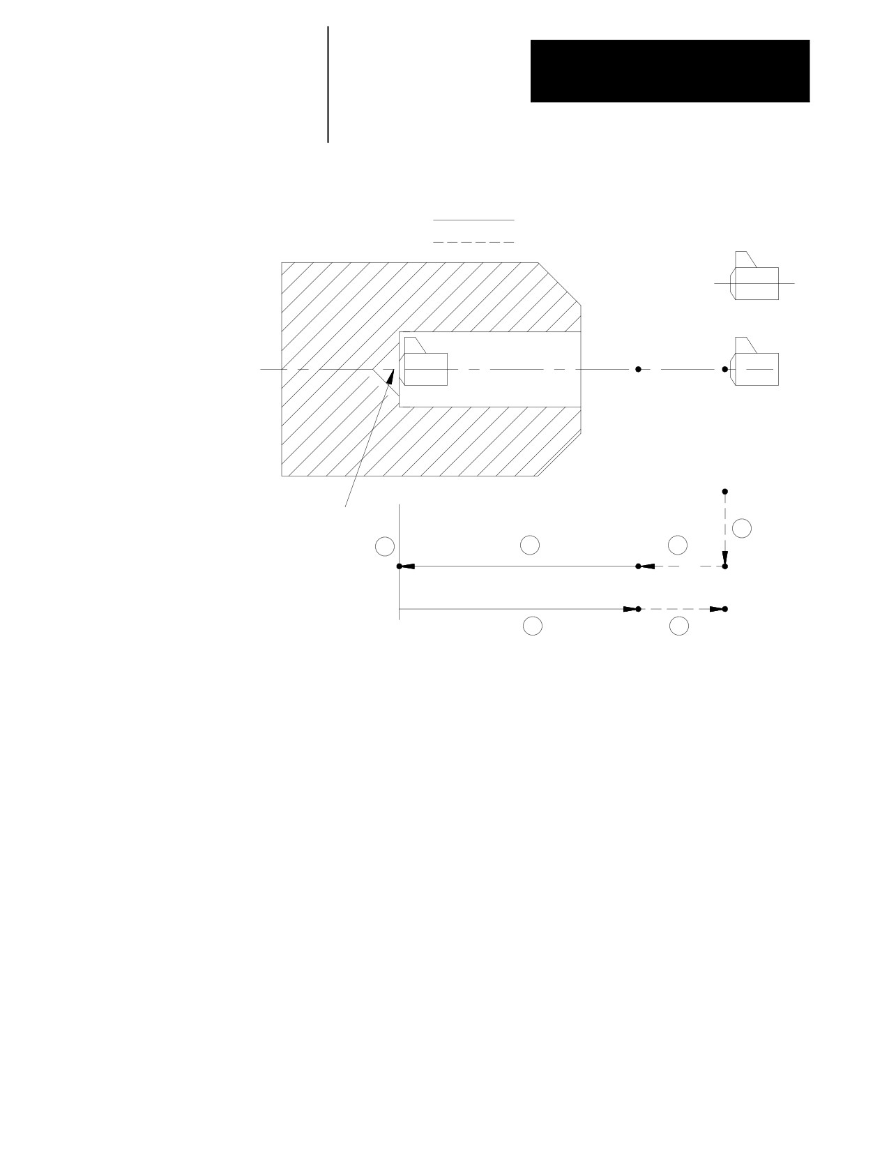
Figure 26.15
G89: Boring Cycle, Dwell/Feed Out
Cutting feed
Rapid feed
R point level
Initial point
level
Hole bottom
1
4
3
2
Z
R
Dwell
5
6
In the G89 boring cycle, the control moves the axes in this manner:
1.
The tool rapids to initial point level above the hole location.
2.
The boring tool then rapids to the R point level, slows to the
programmed cutting feedrate and begins the boring operation.
3.
The boring tool bores at the programmed feedrate until it reaches the
depth of the hole specified by the Z-word.
4.
If the user has entered a value for the P parameter, the boring tool
dwells after it reaches the bottom of the hole.
5.
The control retracts the boring tool at the cutting feedrate to the R
point level.
6.
The boring tool accelerates to the rapid feedrate and retracts to the
initial point level.
When the single block function is active, the control stops axis motion
after steps 1, 2 and 5.
26-37
Chapter 26
Drilling Cycles
26.5
The system installer determines many parameter for the drilling cycles in
AMP. For details on these cycles, see page 26-4 or chapters 22 -- 25.
Altering Drilling Cycle
These 3 parameters may also be changed by the operator by using the
Parameters
Drilling Cycle Parameter screen:
G83.1 Deep Hole Peck Drilling Cycle retract amount - This parameter
determines the value of “d.” “d” for this cycle is the distance above the
last infeed step that the control retracts the tool from the part (normally
to clear chips). See the section on G83.1 Deep Hole Drilling cycle for
details on this cycles operation.
G83 Deep Hole Drilling Cycle clearance amount - This parameter
determines the value of “d.” “d” for this cycle is the distance above the
last infeed step that the feedrate is slowed at to cutting feedrate when
infeeding during this cycle. See the section on G83 Deep Hole Drilling
for details on this cycles operation.
G21 / G78 Threading Cycle
Pullout Distance - This parameter determines the value of “r.” “r”
determines the pullout distance when a thread chamfer or thread retract
operation is performed. This distance is in units of threads. Enter the
number of threads to be chamfered when exiting the thread. This
feature is enabled for threading in PAL or in AMP.
Pullout Angle - This parameter determines the value of “a.” “a”
determines the angle that the chamfer takes when it is performed. This
angle is measure in units of degrees and measured from the same axis as
the thread lead.
To alter these 3 parameters, follow these steps:
1.
Press the {SYSTEM SUPORT} softkey.
(softkey level 1)
PRGRAM
FRONT
MACRO
PRGRAM
SYSTEM
MANAGE
PANEL
PARAM
CHECK
SUPORT
OFFSET
ERROR
PASS-
SWITCH
MESAGE
WORD
LANG
26-38
Chapter 26
Drilling Cycles
2.
Press the {PRGRAM PARAM} softkey.
(softkey level 2)
PRGRAM
AMP
DEVICE
MONI-
TIME
PARAM
SETUP
TOR
PARTS
PTOM
SYSTEM
SI/OEM
TIMING
3.
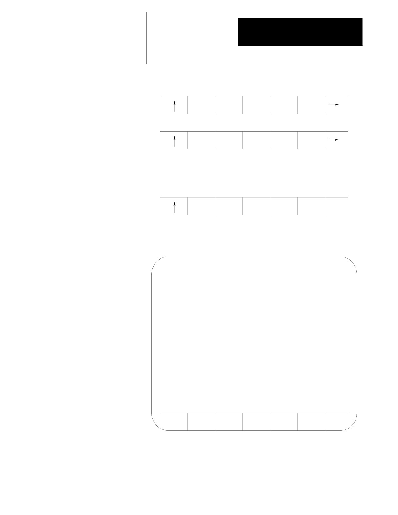
Press the {DRLCYC PARAM} softkey. The Drilling Cycle
Parameter screen is displayed. Figure 26.16 shows a typical Drilling
Cycle Parameter screen.
(softkey level 3)
ZONE
F1-F9
DRLCYC
INTERF
LIMITS
PARAM
CHECK
Figure 26.16
Drilling Cycle Parameter Screen
ENTER VALUE:
DRILLING CYCLE PARAMETERS
G83.1 DEEP HOLE PECK DRILLING CYCLE
RETRACT AMOUNT
1.000 [ MM]
G83 DEEP HOLE DRILLING CYCLE
CLEARANCE AMOUNT
1.270 [ MM]
G86.1/G87 FINE/BACK BORING CYCLE
G18
SHIFT DIRECTION
+Z
G92/G78/G21 SINGLE THREADING CYCLE
PULLOUT DISTANCE
5.1
[THRD]
PULLOUT ANGLE
5
[DEG]
REPLCE
ADD TO
UPDATE
QUIT
VALUE
VALUE
& EXIT
Important: Parameter values are displayed in inch or metric depending on
which is the currently active program mode.
26-39
Chapter 26
Drilling Cycles
4.
From this screen select the parameter that it is desired to change by
pressing the up or down cursor keys. The selected parameter is
shown in reverse video.
5.
There are two options:
To replace the current value of the parameter with a new value,
key in the new value on the input line of the CRT and press the
{REPLCE VALUE} softkey. The new value replaces the old
value.
To add an amount to the current value of the parameter, key in the
amount to add to the current parameter value on the input line of
the CRT and press the {ADD TO VALUE} softkey. The value just
keyed in is then added to the old value for the selected parameter.
6.
To leave the Drilling Cycle Parameter screen, there are two options:
To save the changes just made to the parameters and leave the
Drilling Cycle Parameter screen press the {UPDATE & EXIT}
softkey.
To discard any changes just made to the parameters and leave the
Drilling Cycle Parameter screen, press the {QUIT} softkey.
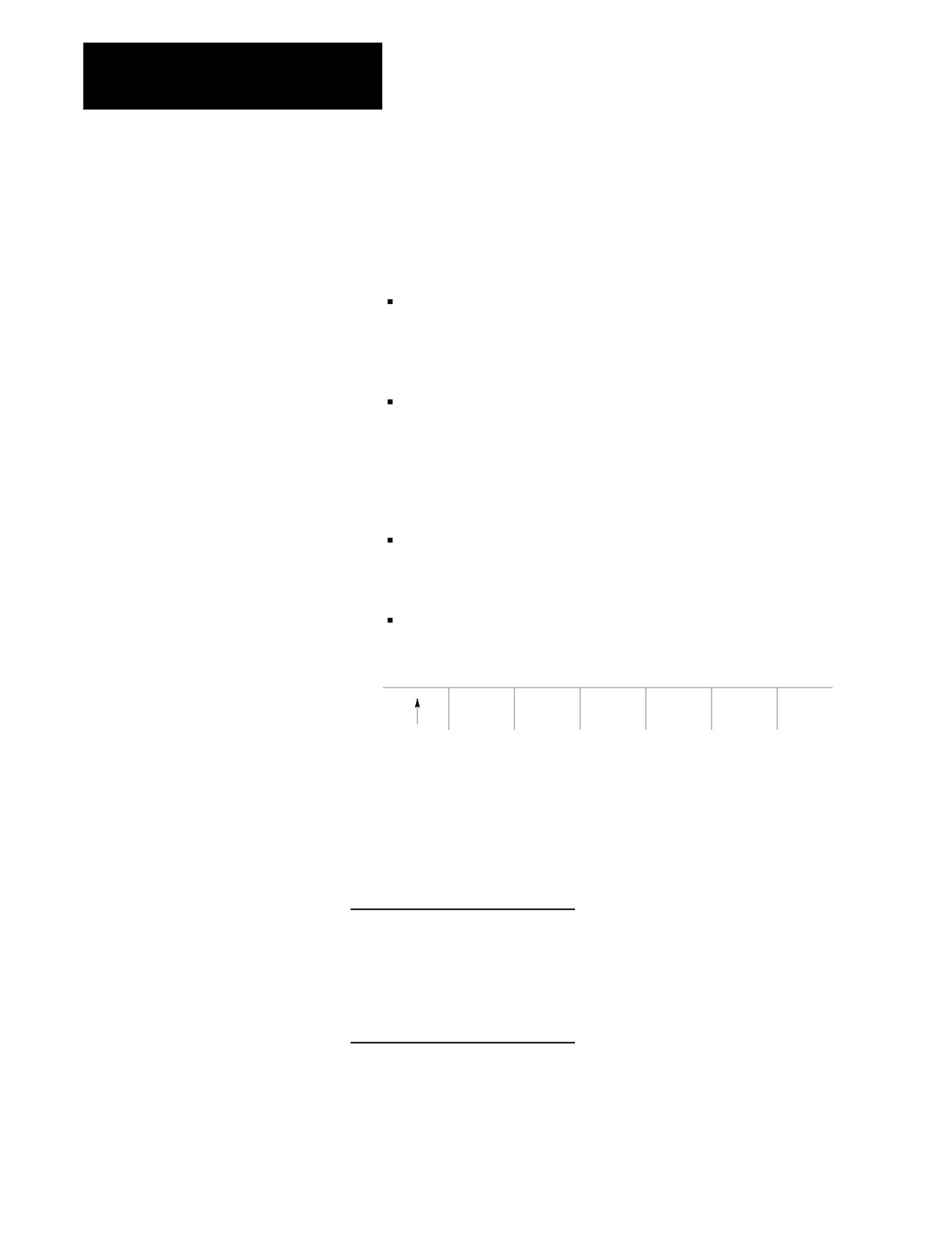
(softkey level 4)
REPLCE
ADD TO
UPDATE
QUIT
VALUE
VALUE
& EXIT
26.6
The following are example programs and an illustration of G83, deep hole
Examples of Drilling Cycles
drilling cycle. Example 27.2 is in incremental mode; Example 27.3 is in
absolute. Figure 26.17 illustrates the result for both programs individually.
Example 27.2
Programming G83, Deep Hole Drilling Cycle in Incremental Mode
N10
M19 S0;
N20
G00 X5 Z0 G90;
N30
G83 X1 Z3 R5 Q1.5 F.1
N40
M19 S90;
N50
Z3;
N60
M30;
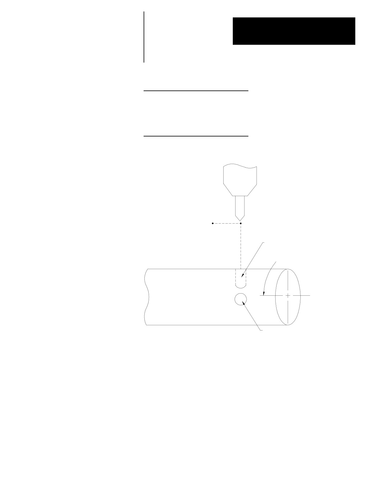
26-40
Chapter 26
Drilling Cycles
Example 27.3
Programming G83, Deep Hole Drilling Cycle in Absolute Mode
N10
G90 G00 X5 Y12 Z0 G17 F200;
N20
G83 X1 Y10 Z-5 R-2 Q1.5;
N30
X5 Y5 Z-8;
N40
X9 Y10 Z-5;
N50
M30;
Figure 26.17
Result of Example 27.2 and Example 27.3
N20
( 5,3 )
( 5,0 )
Second Hole
N30
90°Spindle
N50
( 1,3 )
First Hole
END OF CHAPTER
26-41
Chapter
27
Skip and Gauge Probing Cycles
27.0
This chapter describes the external skip and gauging functions available on
the 9/Series control. External skip functions are motion generating G-code
Chapter Overview
blocks that can be aborted when the control receives an external signal
through the PAL program. Gauging functions are similar to the external
skip functions except that the axis coordinates (at the time the external
signal is received) can be used to modify the tool offset table.
This chapter describes theses major topics in detail.
Topic:
On page:
External skip functions
27-2
Tool gauging external skip function
27-3
Important: The G04 dwell feature may also be enabled as an external skip
or tool gauging command. For details on programming a G04, see chapter
14.
The 9/Series control provides several means of triggering an external skip
or gauging block:
discrete inputs on the I/O ring
any one of the four available “high speed inputs”
a “probe” input that directly latches the feedback counters
These inputs, each with different degrees of precision, may be used to
signal the control to store the current axes positions. See the
documentation prepared by your system installer for details on your
specific machine.
These conditions must be satisfied when an external skip or gauging bock
is executed:
cutter compensation must be disabled (G40 mode) when the block is
executed
the block that contains the external skip G-code (excluding G04 as
external skip) must be a linear block.
27-1
Chapter 27
Skip and Gauge Probing Cycles
CAUTION: We do not recommend using a skip block from any
fixed cycle block (such as drilling or turning). If you do choose
to execute a skip block in a fixed cycle mode, be aware that the
block that is skipped when the trigger occurs can be a cycle
generated block. If this is the case the cycle will continue
normal execution skipping only the portion of the cycle that was
executing when the trigger occurred. If the generated block
skipped is a crucial portion of the cycle, damage to the part or
machine tool can occur.
27.1
Use external skip functions to terminate the execution of motion
External Skip
commands in a block when the control receives a signal through PAL.
When the program block is terminated any remaining axis motion
Functions (G31
codes)
generated by the block that has not been performed remains unexecuted
(other non-motion commands are still performed). The control continues
normal program execution at the beginning of the next block following the
skipped block.
The external skip function is controlled by G31, G31.1, G31.2, G31.3, and
G31.4. The system installer determines what signal (such as a touch probe,
manual switch, etc.) corresponds to each G31 code in PAL. The system
installer can choose different signals to correspond to G31.2, G31.3, and
G31.4. G31 and G31.1 are functionally the same, always using the same
external signal and the same AMP defined feedrate. With proper PAL
programming, a G04 dwell in seconds may also be used as an external
skip function.
Format for any G31 external skip blocks is:
G31 X__ Z__ F__;
Where :
Is :
G31
Any of the G-codes in the G31 series or G04. Use the one that is configured to
respond to the current external skip signal device that is being used.
X, Z
The endpoint of the move if no external skip signal is received. These also
determine the direction that the tool travels in.
F
The external skip function feedrate. If no value is entered here, the external skip
function executes at either the currently active feedrate, or the feedrate defined
for it in AMP (based on whether the AMP parameter Use AMP Skip Feedrate is
set to ”NO”or ”YES”). A value entered here replaces the currently active
feedrate and supersedes the AMP defined feedrate.
The G31 series of G-codes always produce linear motion regardless of the
current mode active at their execution. After their completion the control
returns to the operating mode active before the external skip block was
read (G00, G01, G02, G03).
27-2
Chapter 27
Skip and Gauge Probing Cycles
Important: The move that immediately follows a G31 series external skip
block cannot be a circular move.
The coordinates of the axes when the external skip signal is received are
available as the paramacro system parameters #5061--#5066 (work
coordinate system) and #5071--#5076 (machine coordinate system). These
values will have been adjusted to compensate for the probe tip radius if a
radius compensation value was entered.
For example, assume you have entered a probe tip radius of .01. It is
triggered as axis 2 approaches in the positive direction at the axis 2
coordinate of 1.1200. The value available for paramacro parameter #5072
would be 1.1300
Probe tip radius is defined by the system installer in AMP. This value may
also be changed through the paramacro system parameter #5096.
See the paramacro chapter for details on paramacro parameters.
Skip Function Application Example
A typical application for these G-codes would be to mount the probe as if
it were a tool. When the probe contacts the part and triggers, coordinate
data would be available in the paramacros for use in the remainder of the
part program.
The probe tip radius would be significant for this application.
27.2
Tool gauging functions are similar to external skip functions. The key
Tool Gauging External Skip
difference is that the tool gauging cycles use the actual tool position (when
the external skip signal is received) to enter values in the tool offset table
Functions (G37 codes)
for the currently active offset.
Use tool gauging functions to terminate the execution of motion commands
in a block and modify offset tables when the control receives a signal
through PAL. When the program block is terminated any remaining axis
motion generated by the block that has not been performed remains
unexecuted (other non-motion commands are still performed). The current
tool position is stored, and the control continues program execution at the
beginning of the next block following the skipped block.
The gauging function is controlled by G37, G37.1, G37.2, G37.3, and
G37.4. The system installer determines what signal (such as a touch probe,
manual switch, etc.) corresponds to each G37 code in PAL. The system
installer can choose different signals to correspond to G37, G37.1 G37.2,
G37.3, and G37.4. G37 and G37.1 are functionally the same, always
using the same external signal and the same AMP-defined feedrate.
27-3
Chapter 27
Skip and Gauge Probing Cycles
The format for any G37 skip blocks is:
G37 Z__ F__;
Where :
Is :
G37
Corresponds to any of the G-codes in the G37 series. Use the one that is
configured to respond to the current skip signal device that is being used.
X, Z
The axis on which the length offset measurement is to be taken is specified here
as either X or Z. Only one axis may be specified in a G37 block. The numeric
value following the axis name corresponds to the exact coordinate at which the
skip signal is expected to occur. This value is a signed value (+ or --) and
determines the initial direction of travel.
F
The tool gauging external skip function feedrate. If no value is entered here, the
external skip function executes at either the currently active feedrate or at the
feedrate defined for it in AMP (based on whether the AMP parameter Use AMP
Skip Feedrate is set to ”NO”or ”YES”). A value entered here replaces the
currently active feedrate and supersedes the AMP-defined feedrate.
Important: The G37 series G-codes cannot be used to modify the tool tip
radius values. Only the tool length offset values can be modified.
The target offset value for these gauging operations is determined by the
currently active tool offset number
CAUTION: If modifying a tool length offset, the offset value
generated with this gauging operation is immediately loaded
into the offset table. Since this offset must be the currently
active offset, it becomes effective either immediately when the
next block is executed or delayed until the next block that
contains motion on the tool length axis is executed (when an
offset is activated is determined in AMP by the system
installer).
The G37 series of G-codes always produce linear motion regardless of the
current mode active at their execution. After their completion, the control
returns to the operating mode active before the skip block was read (G00,
G01, G02, G03).
The system installer determines (in AMP) a position tolerance for the G37
functions. This tolerance defines a legal range before and after the
coordinate position programmed with the axis word in the G37 block.
If the skip signal is received before the tool enters or after the tool exits the
position tolerance range, a PROBE ERROR occurs. This error appears on
the screen as a warning but does not place the control in E-Stop. Instead
the G37 block is aborted and program execution proceeds to the next
block. No modification of the tool offset table is performed.
27-4
Chapter 27
Skip and Gauge Probing Cycles
Important: The move that immediately follows a G37 series skip block
cannot be a circular move.
The system installer determines in AMP if the new value is added to or
replaces the old value in the table. The system installer also determines in
AMP what gauge cycles alter which tool offset tables, geometry, or wear.
The control automatically compensates for probe radius and length when
calculating tool offset changes if these probe parameters have been
entered.
The coordinates of the axes when the external skip signal is received are
available as the paramacro system parameters #5061--#5066 (work
coordinate system) and #5071--#5076 (machine coordinate system). These
values will have been adjusted to compensate for the probe tip radius and
the probe length if radius and length compensation values were entered.
For example, assume you have entered a probe tip radius of .01. It is
triggered as axis 2 approaches in the positive direction at the axis 2
coordinate of 1.1200. The value available for paramacro parameter #5072
would be 1.1300
Probe tip radius and probe length are defined by the system installer in
AMP. These values may also be changed through the paramacro system
parameters #5096 (for radius) and #5095 (for length).
See the paramacro chapter for details on paramacro parameters.
Tool Gauging Application Example
A typical application for these G-codes in determining tool length offsets
executes as follows:
1.
When the control executes the G37 block, the tool is moved towards
the triggering device using the axis specified in the block.
2.
When the control receives the appropriate skip signal through PAL,
axis motion stops.
3.
The control records the position when the skip signal is received. It
determines the difference by subtracting the position specified with
the axis word in the G37 block from this position. The difference is
then added to or replaces the value in the appropriate geometry or
wear table for the currently active tool offset number.
27-5
Chapter 27
Skip and Gauge Probing Cycles
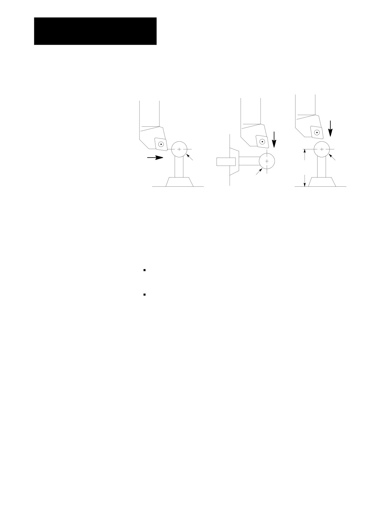
Figure 27.1
Typical Tool Gauging Configurations
Tool
Tool
Tool
--X
--X
Probe
+Z
Probe
Probe
Probe
length
radius
radius
Probe
radius
Probe
Probe
Case 1
Case 2
Case 3
Figure 27.1 illustrates 3 typical tool gauging configurations. All 3 cases
assume that the probe is at a known, fixed point on the machine.
In Case 1, the Z axis tool offset length is being gauged, while in Case 2,
the X axis tool offset length is being gauged. In both cases:
only the probe tip radius is significant to the control in calculating the
offset adjustment
the reference position is the center of the probe ball
In Case 3, the X axis tool offset length is being gauged; and both the probe
radius and the probe length are significant to the control’s offset
adjustment calculations. In this case, the reference position is the bottom
of the probe.
Important: We do not recommend the tool gauging configuration Case 3
depicted in Figure 27.1 due to the risk of probe damage.
END OF CHAPTER
27-6
Chapter
28
Paramacros
28.0
The Paramacrost feature is similar to a subprogram with many added
features. Special features available with a paramacro include:
Chapter Overview
Computable variables
Computable word address fields in any block type
Variable to and from PAL
Access to certain modal system parameters for computations
Arithmetic operators and expressions for computations
Conditional Branching, Subroutines, and Subprogram calls based upon
logical function results
Parametric programs, Subroutines, and Subprograms
Parametric Autocycles
User-definable prompts to aid in program generation and execution
Prompting of parameters for main program execution
Calculator function under prompt edit
All of these features are valid in any block within a main program,
subprogram, or paramacro program. Most are permitted in an MDI
program unless otherwise stated; the only restriction being that no other
program commands, except other paramacro commands, may exist in a
block that contains paramacro commands. Macro and non-macro
commands may not exist in the same program block.
This chapter describes paramacros and and how to program them. Use this
table to find information:
Information on:
On page:
Parametric Expressions
28-2
Transfer of Control Commands
28-7
Parameter Assignments
28-12
Assigning Parameter Values
28-34
Backing Up Parameter Values
28-41
Macro Call Commands
28-42
Macro Output Commands
28-52
28-1

Chapter 28
Paramacros
28.1
It may be necessary for mathematical expressions to be evaluated in a
complex paramacro. This requires that some form of mathematical
Parametric Expressions
equation be written in a paramacro block. The following is a discussion of
the operators and function commands available for use on the control.
These operators and function commands are valid in any block within a
program, subprogram, paramacro, or MDI program.
28.1.1
This subsection lists the mathematical operators that are available on the
9/Series controller. Use these operators to accomplish mathematical
Basic Mathematical
operations that are necessary to evaluate the basic mathematical equation
Operators
such as addition, multiplication, etc. Table 18.A lists the operators and
their meanings.
Table 28.A
Mathematical Operators
Operator
Meaning
+
Addition
-
Subtraction
Multiplication
/
Division
[]
Brackets
OR
Logical OR
XOR
Logical Exclusive OR
AND
Logical AND
MOD
Modulus
The control executes a mathematical operation in this order:
1.
Any part of the expression between the brackets [] is evaluated first.
2.
Multiplication, division, and MOD are evaluated second.
3.
All other operations are evaluated third.
If the same level of evaluation is performed, the left-most operation takes priority.
28-2
Chapter 28
Paramacros
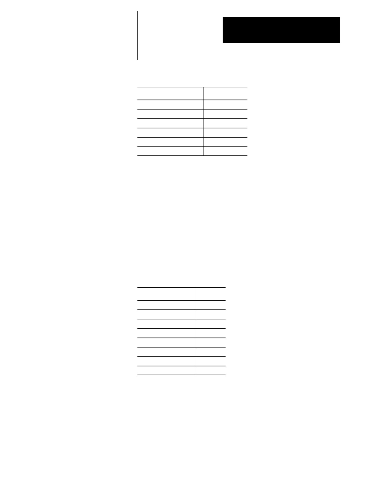
Example 28.1
Mathematical Operations
Expression entered
Result
12/4*3
9
12/[4*3]
1
12+2/2
13
[12+2]/2
7
12-4+3
11
12-[4+3]
5
All logical operators have the format of:
A logical operator B
where A and B are numerical data or a parameters with a value assigned.
If B is negative in the above format, an error will occur.
If A is negative, the absolute value of A is used in the operation and the
sign is attached to the final result.
Before evaluation, A and B are made integers by rounding and truncating.
Example 28.2
Logical Operation Examples
Expression Entered
Result
[16.2MOD3]
1.0
[-16.2MOD3]
-1.0
[-17.6MOD3]
0.0
[16.0MOD3]
1.0
[-5AND4]
-4.0
[4.4AND3.6]
4.0
[5AND-4]
ERROR
[83886079AND83886080]
67108864
28-3

Chapter 28
Paramacros
28.1.2
This subsection lists the basic mathematical functions that are available on
the control and their use. Use these functions to accomplish mathematical
Mathematical Function
operations that are necessary to evaluate the trigonometric and other
Commands
complex mathematical equation such as rounding off, square roots,
logarithms, exponent, etc. NO TAG lists the basic functions that are
available and their meanings.
Table 28.B
Mathematical Functions
Function
Meaning
SIN
Sine (degrees)
COS
Cosine (degrees)
TAN
Tangent (degrees)
ATAN
Arc Tangent (degrees)
ASIN
Arc Sine (degrees)
ACOS
Arc Cosine (degrees)
SQRT
Square Root
ABS
Absolute Value
BIN
Conversion from BCD to Decimal
BCD
Conversion from Decimal to BCD
ROUND
Rounding Off (nearest whole number)
FIX
Truncation Down
FUP
Truncation Up
LN
Logarithms (base e)
EXP
Exponent
When programming these functions, the value on which that function is to
be performed must be included in brackets: for example, SIN [10]. The
exception to this is the arc tangent function. The format to ATAN requires
the division of two values. For example, ATAN [10]/[2] is used to
calculate the arc tangent of 5.
The functions in NO TAG are executed from left to right in a program
block. These functions are executed before the control executes any
mathematical operators such as addition or subtraction. This order of
execution can be changed only by enclosing operations in brackets [].
Operations enclosed in brackets are executed first.
28-4
Chapter 28
Paramacros
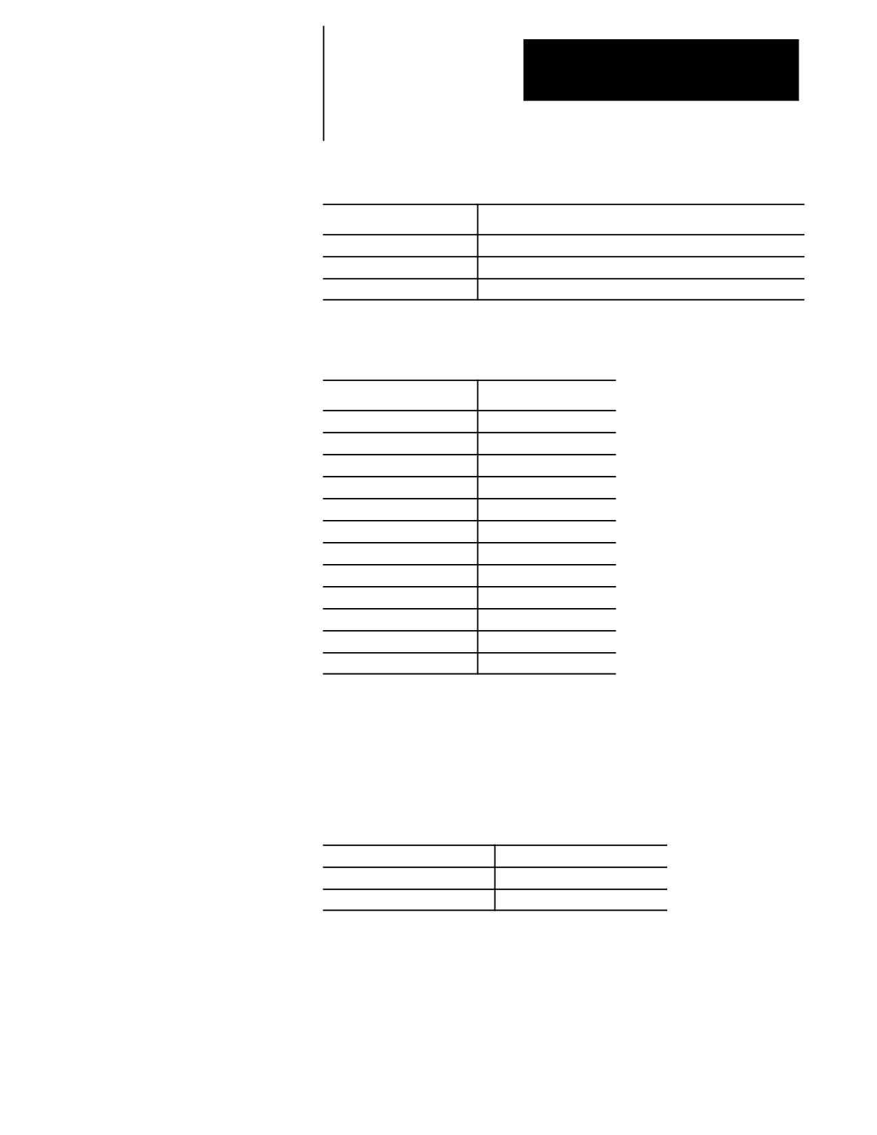
Example 28.3
Format for Functions
SIN[2]
This evaluates the sine of 2 degrees.
SQRT[14+2]
This evaluates the square root of 16.
SIN[SQRT[14+2]]
This evaluates the sine of the square root of 16.
LN[#2+4]
This evaluates the logarithm of the value of parameter #2 plus 4.
Example 28.4
Mathematical Function Examples
Expression Entered
Result
SIN[90]
1.0
SQRT[16]
4.0
ABS[-4]
4.0
BIN[855]
357
BCD[357]
855
ROUND[12.5]
13.0
ROUND[12.4]
12.0
FIX[12.7]
12.0
FUP[12.2]
13.0
FUP[12.0]
12.0
LN[9]
2.197225
EXP[2]
7.389056
Important: Precaution must be taken when performing calculations within
the brackets [] following a mathematical function. The operations within
the bracket are performed first, and then the function is performed on this
resultant.
Example 28.5
Precaution for Order of Operation
N1#1=1.6;
Parameter #1 is set at 1.6
N2#2=2.8;
Parameter #2 is set at 2.8
N3#3=ROUND[#1+#2];
Parameter #3 is set at 4.0
Note that the values composing parameter #3 are added together first and
then rounded, not rounded and then added together.
28-5
Chapter 28
Paramacros
28.1.3
You can use parametric expressions to specify G-codes or M-codes in a
program block.
Parametric Expressions as
G- or M-Codes
For example:
G#1 G#100 G#500 M#1 M#100 M#500;
G#520 G[#521-1] G[#522+10] M#520 M[#522+1] M[#522+10];
When using a parametric expression to specify a G-- or M-code, remember:
When specifying more than one G-- or M-code in a block from the same
modal group, the G-- or M-code closest to the End-of-Block of that
block is the one activated. All others in that modal group are ignored.
Parametric expressions that generate G-- or M-codes used to call a
paramacro are invalid. If the result of the paramacro expression for a
G-code is 65, 66, 66.1, or any AMP-defined G-code, the error
“ILLEGAL G-CODE” appears. If the result of the paramacro
expression for an M-code is any AMP-defined M-code, the control will
not execute the macro but interpret the M--code as either a system
defined M--code or a user defined M--code. No error is generated.
To get the G-- or M-code value, the system will truncate, after the tenths
position, the result of the mathematical expression. The following
example assumes #1=37.0:
This Block
Generates This G-Code
G#1
G37.0
G[#1+0.32]
G37.3
G[#1+0.49]
G37.4
Illegal Paramacro Commands
It is possible to call subprograms or paramacros within an MDI program,
however, there are limitations to the allowable commands. The following
lists examples of illegal MDI commands for these features:
G66
G66.1
G67
DO--END
WHILE--DO--END
GOTO
IF--GOTO
M99
Amp--defined Modal G--code Macro Calls
Attempting to use any of the above as MDI commands, 9/Series generates
an “ILLEGAL MACRO CMD VIA MDI” error message.
28-6

Chapter 28
Paramacros
28.2
Use transfer of control commands to alter the normal flow of program
execution. Normally the control executes program blocks sequentially.
Transfer of Control
By using control commands, the programmer can alter this normal flow of
Commands
execution and transfer execution to a specific block or begin looping
(executing the same set of blocks repetitively).
Important: Transfer of control commands call a block by its N number. If
more than one N number exists in a block, the control uses only the
left-most N number in that block. If the same N number is used for more
than one block, the control will use the first block it encounters with the
correct N number (the control searches in the forward direction first, then
starts at the top of the program).
Two types of transfer of control commands are available:
Conditional ---- The execution of a jump or loop is dependant on
whether a mathematical condition is true.
Non-Conditional ---- The execution of a jump or loop is always
performed when that block is executed.
28.2.1
This section describes conditional operators that are available for
paramacro programming. A conditional operator causes a comparison
Conditional Operators
between two values and yields a result of true or false. Use conditional
operators in “IF” or “WHILE” commands as described on page 28-9 and
28-10.
Use the true or false condition to determine whether the “IF” or “WHILE”
blocks are executed. NO TAG lists the conditional operators available for
paramacro programming:
Table 28.C
Conditional Operators
Operator
Condition Tested
EQ
Equal
NE
Not Equal
GT
Greater Than
LT
Less Than
GE
Greater Than or Equal
LE
Less Than or Equal
28-7
Chapter 28
Paramacros
Program a condition between the [ and ] brackets in this format:
[A EQ B]
where A and B represent some numerical value. The values for A and B
can be in the form of some mathematical equation or in the form of a
paramacro parameter.
Example 28.6
Evaluation of Conditional Expressions
Expression
Evaluation
[6.03 EQ 6.0301]
FALSE
[6.03 NE 6.0301]
TRUE
[2.5 GT 2.5]
FALSE
[2.5 LT 2.51]
TRUE
[2.51 GE 2.5]
TRUE
[2.5 LE 2.5]
TRUE
[[2.5-3] LE 1]
TRUE
[#1 GT #2]
This depends on the value of the parameters #1 and #2
For details on the use of conditional expressions, refer to page 28-9 on
“IF” statements and page 28-10 on “WHILE” statements. For details on
the use of paramacro parameters, refer to page 28-12.
28.2.2
Unconditional GOTO
GOTO and IF-GOTO
Any time the control executes a GOTO block, the unconditional GOTO
Commands
command automatically transfers control.
Use this format for the GOTO command:
GOTO n;
Where :
Is:
n
Execution is transferred to the block with the sequence number specified as n
any time that the GOTO block is executed.
28-8
Chapter 28
Paramacros
Example 28.7
Unconditional GOTO
N1...;
N2...;
N3GOTO5;
N4...;
N5...;
N6...;
/N7GOTO1;
In Example 28.7, execution continues sequentially until block N3 is read;
then execution transfers to block N5 and again resumes sequential
execution to block N6. If optional block skip 1 is off, block N7 will
transfer execution back to block N1.
Conditional IF-GOTO
The conditional IF-GOTO command is dependent on whether a
mathematical condition is true. If this condition is true, execution will
transfer to the block specified.
Use this format for the IF-GOTO command:
IF [(condition)] GOTO n;
Where :
Is :
(condition)
some mathematical condition. This condition is tested by the control to determine if
it is true or false.
n
if the condition is tested as true, execution is transferred to the block specified as n
If the condition is tested as false, execution falls through the block and the
GOTO is not executed. Program execution continues in a normal fashion.
Example 28.8
Conditional IF
N1...;
N2IF[#3EQ-1.5]GOTO5;
N3...;
N4...;
N5...;
N6IF[#4LT3]GOTO1;
N7...;
28-9
Chapter 28
Paramacros
When block N2 is read, parameter #3 is compared to the value -1.5. If the
comparison is true, then blocks N3 and N4 are skipped, and execution
continues on from block N5. If the comparison is false, then execution
continues to block N3. When block N6 is read, parameter #4 is compared
to the value 3. If the comparison is true, then execution is transferred to
block N1; if it is false, execution continues to block N7.
28.2.3
Unconditional DO-END
DO-END and
The unconditional DO-END command is rarely used. The lack of a
WHILE-DO-END Commands
condition here causes the control to loop indefinitely until reset or
<CYCLE STOP> is pressed, or until some other transfer of control command
forces execution out of the loop.
The format for the unconditional DO-END command is as follows:
DO m;
:
:
:
END m;
Where :
Is :
m
a loop identifier used to relate a DO block with an END block. The value of m
must be the same for the DO as it is for the corresponding END. This value can
be either 1, 2, or 3.
All blocks between the DO and the END command are executed
indefinitely or until execution is stopped by some external operation such
as by pressing <E-STOP> or <CYCLE STOP>, or when a block delete is
performed if programmed.
Conditional WHILE-DO-END
The conditional WHILE-DO-END command is dependant on whether a
mathematical condition is true. If this condition is false, execution will
transfer to the block immediately following the END statement block.
28-10
Chapter 28
Paramacros
Use this format for the WHILE-DO-END command:
WHILE [ (condition) ] DO m;
;
;
;
END m;
Where :
Is :
(condition)
some mathematical condition. This condition is tested by the control to
determine if it is true or false.
m
an identifier used by the control to relate a DO block with an END block. The
value of m must be the same for the DO as it is for the corresponding END. This
value can be either 1, 2, or 3.
All blocks between the DO and the END command are executed until the
condition is tested as false. This set of blocks is referred to as a
WHILE-DO-END program segment.
When the condition for the WHILE-DO block is tested as false, execution
is then transferred to the block immediately following the END statement
block.
Example 28.9
WHILE-DO-END Program Segment
N1 #1=1;
N2WHILE[#1LT10]DO1
N3#1=[#1+1];
N4...;
N5...;
N6END1;
N7...;
In Example 28.9, blocks N2 through N6 are executed 9 times. At that
time, the condition in block N2 becomes false, and program execution is
transferred to block N7.
Nesting is possible with a WHILE-DO-END command. Nesting is defined
here as one WHILE-DO-END program segment executing within another
WHILE-DO-END program segment. WHILE-DO-END nesting is limited
to 3 independent segments at one time.
28-11
Chapter 28
Paramacros
Example 28.10
Nested WHILE DO Commands
N1#1=1;
N2WHILE[#1LT10]DO1;
N3#1=[#1+1];
N4WHILE[#1EQ2]DO2;
N5...;
N6END2;
N7END1;
N8...;
In Example 28.10, blocks N2 through N7 are repeated until the condition
in block N2 becomes false. Within DO loop 1, DO loop 2 will be repeated
until the condition in block N4 becomes false.
28.3
The following subsections describe assigning different paramacro
parameter values and how these parameters are used in a paramacro. Use
Parameter Assignments
parameters for paramacros to replace a numeric value. They can be said to
be used as a variable.
There are 5 types of parameters that may be called for use in a paramacro:
local - independent set of variables assigned to each nested macro
common - variables available to all programs
system - variables that indicate specific system condition
PAL - provide variables shared between part and PAL programs
dual process - provide variables shared between processes
The following subsections describe these different types of parameters
independently. This in no way means that they are not interchangeable in
the same macro program. Mixing the different types of parameters in the
same paramacro is acceptable.
28.3.1
Local parameters are #1 - #33. There are 5 sets of local parameters. The
Local Parameter
first set is reserved for use in the main program and any subprogram called
by that main program with an M98. The remaining four sets are for each
Assignments
nested level of macro (4 levels of nesting maximum).
Assigned parameter values are specific to the individual macro nesting
levels. Local parameters are assigned as described on page 28-34.
28-12
Chapter 28
Paramacros
Local parameters are used in a specific macro to perform calculations and
axis motions. After their initial assignment, these parameters can be
modified within any macro at the same nesting level. For example macro
O11111 called from a main program has 33 local parameter values to work
with (#1 to #33). All macros called from the main program, and nested at
the same level, use the same local parameters with the same values unless
they are initialized in that macro.
For example macro O11111 called from a main program assigns a value to
#1 = 1 and the macro returns execution to the main program with an M99.
Later in the same main program (before executing an M99, M02, or M30)
macro O11111 is called from the main program again. The value assigned
to #1 (=1) remains from the previous macro that executed at that nesting
level.
Important: Any local variables you intend to use in a macro we
recommend you initialize them before you start using them unless you
require values passed from a macro at the same nesting level. In our
example above where macro O11111 assigns #1=1. The value of #1 is
carried to any macro that is nested at the same nesting level. If for
example after macro O11111 returns control to the main program a
different macro O22222 is called, the same set of local variables is
assigned to O11111 and O22222 because they are both nested at level 1.
Confusion could be prevented if before macro O22222 uses #1 it initializes
that variable using #1 = 0. All local variables are reset to zero when the
control executes an end of program block (M02 or M30) or a program
restart code (M99 in a main program).
Considerations for Local Parameters
When assigning values to local parameters, remember:
All local variable assignments are reset to zero any time the control
reads an M02 or M30 in a part program or an M99 in a main program.
All local variable assignments are reset to zero any time that power is
turned on, the control is reset, or an E-STOP reset operation is executed.
If more than one I,J, or K set is programmed in an argument, use
NO TAG (B) on page 28-35 for the parameter assignment.
28-13

Chapter 28
Paramacros
Example 28.11
Assigning Using More Than One I, J, K Set
G65P1001K1I2J3J4J5;
The above block sets the following parameters:
parameter #6 = 1
parameter #7 = 2
parameter #8 = 3
parameter #11 = 4
parameter #14 = 5
If the same parameter is assigned more than one value in an argument, only
the right-most value is stored for the parameter.
Example 28.12
Assigning the Same Parameter Twice
G65P1001R3.1A2R-0.5
The above block sets the following parameters:
parameter #1 = 2.0 As set by the A--word
parameter #18 = -0.5 As set by the last R--word.
The 1st value of 3.1, assigned to parameter #18 by the R--word, is
replaced by the 2nd value set by the second R--word.
Example 28.13
Assigning The Same Parameter Twice Using I, J, and K
G65P1001R2I3.4D5I-0.6
The above blocks set the following parameters:
parameter #18 = 2 As set by the R--word.
parameter #4 = 3.4 As set by the 1st I--word.
parameter #7 = -0.6 As set by the 2nd I--word.
The 1st value of 5, assigned to parameter #7 by the D--word,
is replaced by the 2nd value set by the second I--word.
28-14
Chapter 28
Paramacros
28.3.2
The common parameters refer to parameter numbers 100 to 199 and 500 to
999 for all 9/Series controls except for the 9/240, which allows 100 to 199
Common Parameters
and 500 to 699. The common parameters are assigned through the use of a
common parameter table as described on page 28-38.
Common parameters are global in nature. This means that the same set of
parameters can be called by any program, macro, subprogram, or MDI
program.
Common parameters are divided in to two types: saved or unsaved.
Saved common parameters refers to the common parameters that retain
their value even after power to the control is lost. Saved common
parameters are parameter numbers 500 - 999 for all 9/Series controls
except the 9/240, which allows only 500 to 699.
Unsaved common parameters refers to the common parameters that do
not retain their value after power to the control is lost. When power to
the control is turned back on, these parameters reset their value to zero.
Unsaved common parameters are numbers 100 - 199.
The PAL programmer can use some of these parameters to check
parametric values with the Paramacro Range Check feature. For more
information refer to the description of $PRMQTY and $PRMERR in your
9/Series CNC PAL Reference Manual.
28.3.3
System parameters may be used by any part program, including
paramacros and subprograms. All of these parameters may be used as data
System Parameters
or may be changed by assignment (read and write) unless indicated
differently in NO TAG.
These system parameters are generated by the control and can be modified
by operation or programming. They correspond to different control
conditions such as current operating modes, offsets, etc.
NO TAG lists the system parameters available on the 9/Series control.
28-15
Chapter 28
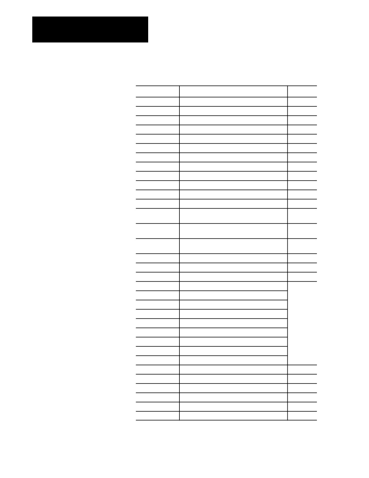
Paramacros
Table 28.D
System Parameters
Parameter #
System Parameter
Page
2001 to 2999
Tool Offset Tables
28-17
3000
2 Program Stop With Message (PAL)
28-17
3001
System Timer (PAL)
28-18
3002
System Clock
28-18
3003
2 Block Execution Control 1
28-19
3004
2 Block Execution Control 2
28-19
3006
2 Program Stop With Message
28-20
3007
1 Mirror Image
28-20
4001 to 4120
1 Modal Information
28-21
5001 to 5012
1 Coordinates of End Point
28-22
5021 to 5032
1 Coordinates of Commanded Position
28-22
5041 to 5052
1 Machine Coordinate Position
28-23
5061 to 5069 or
1 Skip Signal Position (Work Coordinate)
28-23
5541 to 5552
5071 to 5079 or
1 Skip Signal Position (Machine Coordinates)
28-24
5561 to 5572
5081 to 5089 or
1 Active Tool Length Offsets
28-25
5581 to 5592
5095 to 5096
Probe Stylus Length and Radius
28-25
5101 to 5112
1 Current Following Error
28-25
5201 to 5212
External Offset Amount
28-26
5221 to 5232
G54 Work Coordinate Table Value
28-26
5241 to 5252
G55 Work Coordinate Table Value
5261 to 5272
G56 Work Coordinate Table Value
5281 to 5292
G57 Work Coordinate Table Value
5301 to 5312
G58 Work Coordinate Table Value
5321 to 5332
G59 Work Coordinate Table Value
5341 to 5352
G59.1 Work Coordinate Table Value
5361 to 5372
G59.2 Work Coordinate Table Value
5381 to 5392
G59.3 Work Coordinate Table Value
5630
1 S--Curve Time per Block
28-28
5661 to 5642
1 Acceleration Ramps for Linear Acc/Dec Mode
28-29
5651 to 5662
1 Deceleration Ramps for Linear Acc/Dec Mode
28-28
5671 to 5682
1 Acceleration Ramps for S--Curve Acc/Dec Mode
28-30
5691 to 5702
1 Deceleration Ramps for S--Curve Acc/Dec Mode
28-29
5711 to 5722
1 Jerk
28-30
28-16