9/Series CNC Lathe. Operation and Programming Manual - page 25
Chapter 28
Paramacros
The L--word or any optional argument statements following a G66.1 can
contain any valid mathematical expression. For example:
G66.1 P1002 L[#1+1] A[12*6] B[SIN[#101]];
Example 28.20
G66.1 Macro Operation
N0100G90G17G00;
N0110G66.1P9400;
Macro 9400 is executed.
N0120G91G18G01;
G91 and G18 become effective, 01 is assigned to parameter
#10, macro 9400 is executed.
N0130G03X1.;
03 is assigned to parameter #10, 1. is assigned to parameter
#24, macro 9400 is executed.
N0135;
Macro 9400 is executed.
N0140G67;
Macro 9400 is deactivated.
N0150M30;
program end.
Any time the macro is called (while executing the G66.1), the L--word
programming the number of repetitions is in effect. Any attempt to
reprogram an L--word outside of a G66.1 block is interpreted as an
argument assignment for parameter #12.
Important: When nesting a macro (any macro including G66.1) within a
G66.1 macro, the outer G66.1 macro is executed after each individual
block of the nested macro, except for paramacro command blocks such as
assignment, goto, etc.
Example 28.21
Nesting a Modal Macro
N0100G66.1P1001;
N0200G65P1002;
After the execution of each individual block within the macro 1002, the
macro 1001 is called.
You can define the L--word or any optional argument statements in a G66.1
block as any valid parametric expression. For example:
G66.1 P1002 L[#1+1] A[12*6] B[SIN[#101]];
28-47

Chapter 28
Paramacros
28.5.4
Use this format for calling an AMP-defined macro:
AMP-defined G-Code Macro
G_ A_ B_;
Call
Where :
Is :
G_
Programs an AMP-defined G-code command (from G1 to G255.9).
A-Z
Optional argument statements. May be programmed using any letter from A to Z
excluding G, L, N, O, or P. Used to assign numeric values to parameters in the
paramacro (see NO TAG). Arguments may be specified as any valid parametric
expression.
An AMP-defined G-code macro is a G-code that is specified in AMP by
the system installer. When one of these AMP-defined G-codes is executed
in a part program, execution is transferred to the macro with the program
number associated to that G-code.
G-code values for paramacro calls may range from 1 to 255.9. The system
installer may define a maximum of 25 AMP-defined G-codes to call
specific paramacro programs. The paramacro program name called with
the AMP-defined G-code is a program number from 1 to 8999 or 9010 to
9019. Refer to the system installer’s documentation for details.
Important: The system installer may disable the use of AMP-defined G
and M-code macro calls when in MDI mode. Refer to the system
installer’s documentation to determine if this feature is functional in MDI.
AMP-defined G-code macros can be executed as either modal or
non-modal macros as selected in AMP. If selected as modal, they can be
execute using either G66 modality or G66.1 modality. This modality type
for AMP defined G-codes is also determined by the system installer in
AMP.
Any optional argument statements following an AMP-defined G-code may
contain any valid parametric expression. For example:
G255A[12*6]B[SIN[#101]];
In a part program, if more than one digit is entered after the decimal point,
the value will be truncated. For example, 231.18 is 231.1, and 231.14 is
231.1.
Important: Certain AMP-defined G-code Macro calls cannot be called by
any other AMP-defined macro call.
28-48

Chapter 28
Paramacros
28.5.5
Use this format for calling an AMP-defined M-code macro:
AMP-Defined M-Code Macro
M255 A_B_
Call
Where :
Is :
M255
Programs an AMP-defined M-code command.
A-Z
Optional argument statements. May be programmed using any letter from A to Z
excluding G, L, N, O, or P. Used to assign numeric values to parameters in the
paramacro (see NO TAG). Arguments may be specified as any valid parametric
expression.
These macros are executed only as non-modal macro.
The term AMP-defined M-code macro comes from the fact that the
M-code that calls a specific macro program is specified in AMP by the
system installer. The system installer may define M-codes that will call
paramacro programs with program names ranging from 9001 to 9009.
Refer to the system installer’s documentation to determine what M-codes
are used to call what paramacro program name.
When one of these AMP assigned M-codes is specified in a part program,
execution is transferred to the macro associated to that specific M-code.
M-code values for paramacro calls may range from -1 to 999. The system
installer may define a maximum of 9 AMP-defined M-codes to call
specific paramacro programs.
Important: Note the system installer may optionally disable the use of
AMP-defined G-- and M-code macro calls when in MDI mode. See the
system installer’s documentation to determine if this feature is functional
in MDI.
28.5.6
Use this format for calling an AMP-defined T--, S--, or B--code macro:
AMP-Defined T- , S- , and
T t ;
B-Code Macro Call
S s ;
or
B b ;
Where :
Is equal to the value assigned to parameter:
t
#149
s
#147
b
#146
Important: Programming arguments are not allowed with the
AMP-defined T--, S--, or B--code macro calls.
28-49
Chapter 28
Paramacros
These macros are executed only as non-modal macro.
The execution of the T--, S--, or B--code macro calls is the same as M-code
macro calls with the following exceptions:
the parameter # referenced when called
the macro program called
T calls macro 9000
S calls macro 9029
B calls macro 9028
In order for the T--, S--, or B--words to call up a macro program, these
prerequisites must be met:
1.
The value following the word must be equal to the value stored for
the specified parameter #.
For example:
T14;
The value of 14 must have been previously stored as the value for the
parameter #149.
2.
An AMP flag for that specific word must be turned on by the system
installer to allow that word to call a macro.
3.
The value for an AMP-defined T--, S--, or B--code command has the
same format and range as an ordinary T--, S--, or B--code.
28.5.7
Nesting occurs when one program calls another program. A subprogram
called by a main program is an example of nesting. (The “nested” program
Nesting Macros
is the program called.)
Nesting applies to macros as well. When the main program calls a macro,
the macro is said to be on nesting level 1. If this macro in turn calls
another macro, this second macro is said to be in nesting level 2. Macros
may be nested up to a maximum of 4 levels. However, if the maximum
number of nested paramacros (4) is combined with up to 4 subprograms
that end with M98, a maximum of 8 levels of nesting can be programmed.
What is not counted as an additional nested level? When a lower nested
macro with a modal feature forces a higher nested macro to call it, the
number of nested levels does not increase. Nor does it increase when a
subprogram is called using M98.
28-50
Chapter 28
Paramacros
Precautions must be taken when attempting to nest AMP assigned macro
calls since many combinations of these calls may not be valid. The system
installer determines in AMP the functionality of the AMP-defined macro
call when nested. These two options are available (see the system
installer’s documentation to determine which applies to your system):
Works as a macro call -- When “works as a macro call” is selected, G--,
M--, T--, S--, or B--code macro calls that are nested and called by other
G--, M--, T--, S--, or B--code macro calls allow nesting as shown in
NO TAG.
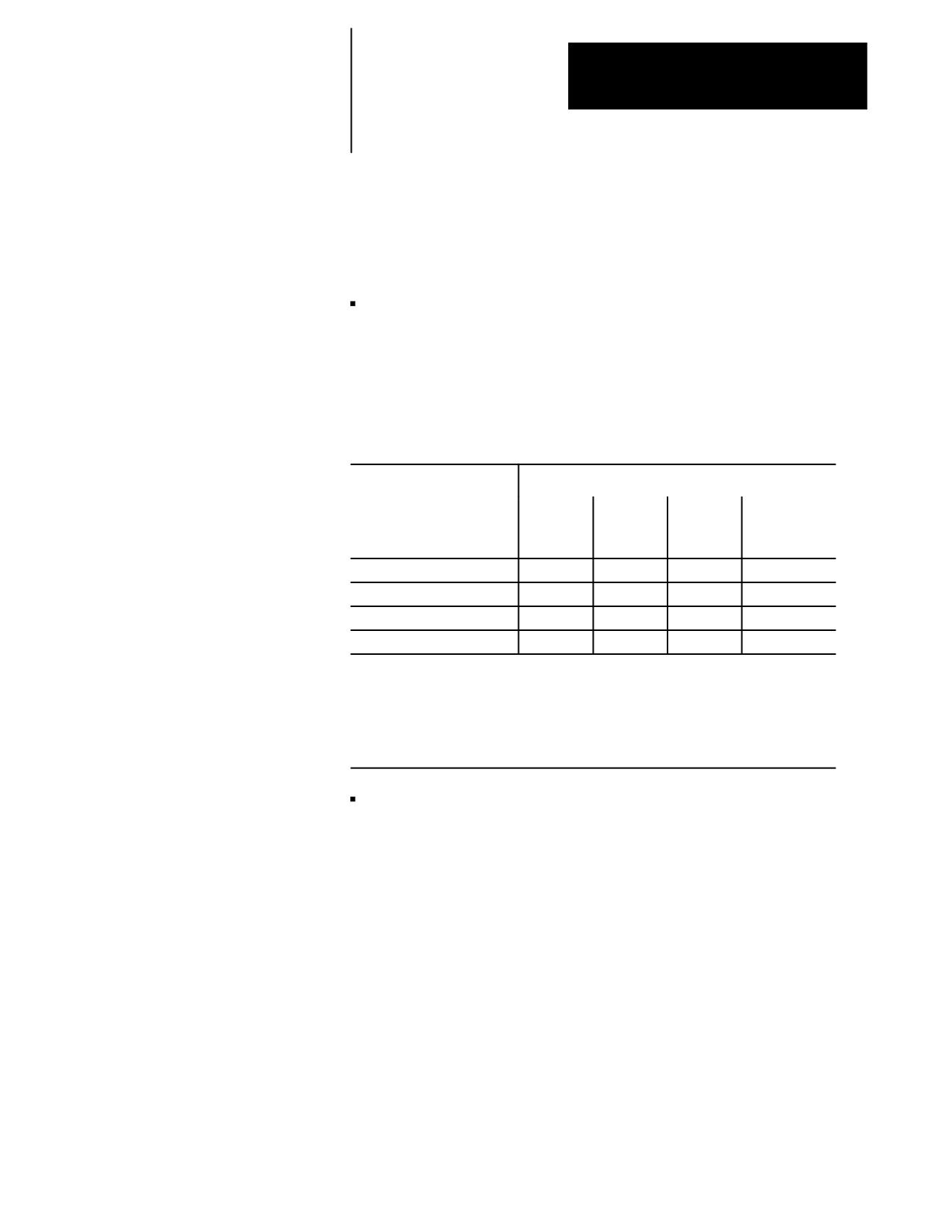
Table 28.I
Works as a Macro Call
CALLING PROGRAM
TYPE OF MACRO NESTED1
G65,
G66,or
AMP-T
G66.1
AMP-G
AMP-M
S or B
G65, G66 or G66.1
Yes
Yes
Yes
Yes
AMP G-code
Yes
No
Yes
Yes
AMP M-code
Yes
Yes
No
No
AMP-T--, S--, or B--code
Yes
yes
No
No
1 What Yes/No means:
Yes ---- the macro type across the top row may be called from the macro type down the left column.
No ---- the macro type across the top row may not be called from the macro type down the left column.
When this nesting is attempted, the control will execute any other operation that would normally be
performed by that G--, M--,T--, S--, or B--code (as defined by the system as a standard code, PAL, or
some other AMP feature) and the paramacro call normally made by that code is not performed.
Works as the system-defined code -- When “works as the system
defined code” is selected, G--, M--, T--, S--, or B--code macro calls that
are nested and called by other G--, M--, T--, S--, or B--code macro calls
allow nesting as shown in NO TAG.
28-51
Chapter 28
Paramacros
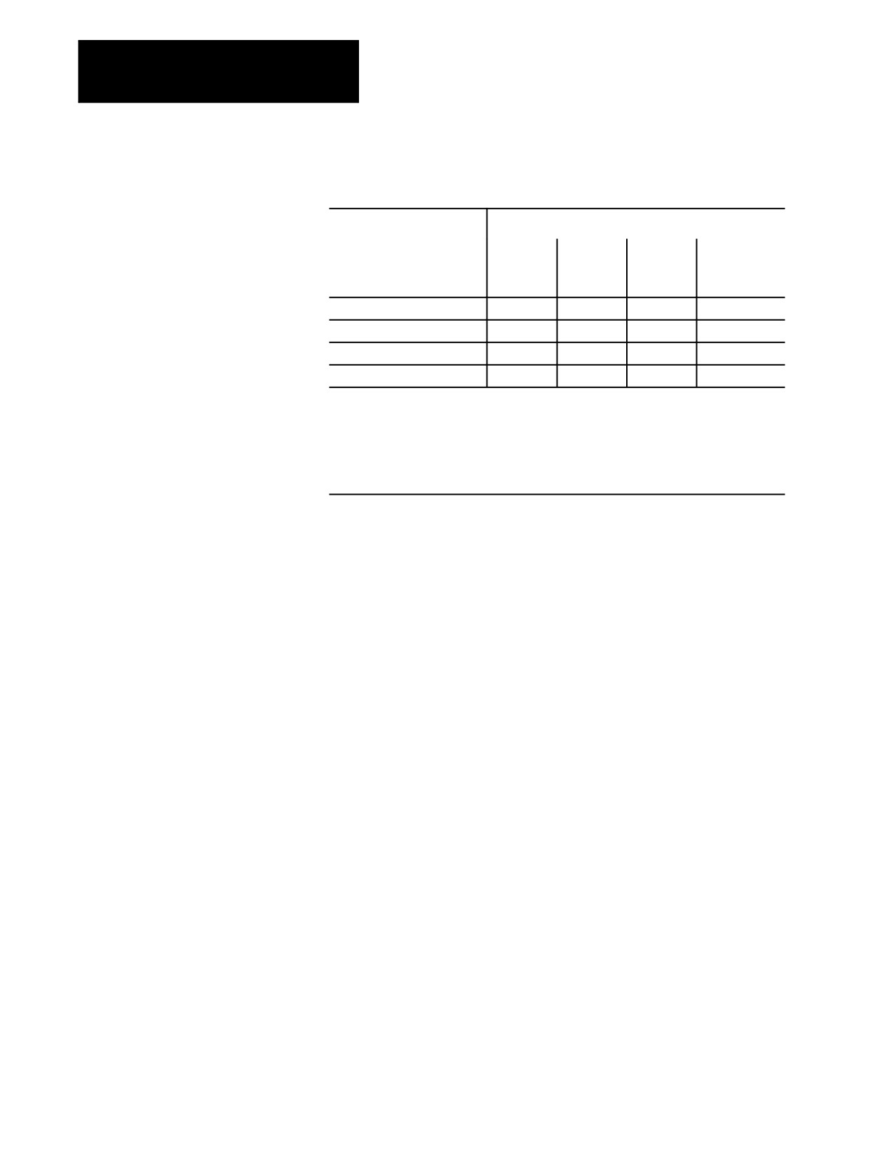
Table 28.J
Works as the System-defined Code
CALLING PROGRAM
TYPE OF MACRO NESTED1
G65,
G66,or
AMP-T
G66.1
AMP-G
AMP-M
S or B
G65, G66 or G66.1
Yes
Yes
Yes
Yes
AMP G-code
Yes
No
No
No
AMP M-code
Yes
No
No
No
AMP-T--, S--, or B--code
Yes
No
No
No
1 What Yes/No means:
Yes ---- the macro type across the top row may be called from the macro type down the left column.
No ---- the macro type across the top row may not be called from the macro type down the left column.
When this nesting is attempted, the control will execute any other operation that would normally be
performed by that G--, M--, T--, S--, or B--code (as defined by the system as a standard code, PAL, or
some other AMP feature) and the paramacro call normally made by that code is not performed.
Important: If the nesting is invalid (No in one of the above tables), the
control will execute the programmed code as some other function (as
defined by the control as a standard code, PAL, or some other AMP
feature) and the macro call is not made. If no other function is found that
uses that G--, M--, T--, S--, or B--code, the control generates an error.
The rule to follow for NO TAG is that an AMP-assigned macro may not
call an AMP-assigned macro.
For example, if the calling program is an AMP-assigned M-code
macro, then G65, G66 and G66.1 macro calls are allowed; but no
other types of macro calls are allowed, including an M-code macro.
28.6
Paramacros have the ability to force the control to output selected
parameter values to a device attached to the RS-232 port. This is done by
Macro Output Commands
using one of these commands in any macro or MDI program block:
POPEN
PCLOS
BPRNT
DPRNT
Upon execution of these commands in a program block, the control outputs
the appropriate data (in the form of part program blocks such that they may
be output to an RS-232 compatible device).
28-52

Chapter 28
Paramacros
POPEN
This command affects a connection to the output device by sending a DC2
control code and a percent character “%” to the RS-232 interface. This
command must be specified prior to outputting any data. After this
command, the control outputs any following program blocks including the
parameter values that are used in them.
The format for a POPEN block is:
POPEN;
PCLOSE
This command disconnects the control from the output device by sending a
DC4 control code and a percent character “%” to the RS-232 interface.
This command must be specified after all data have been output. This
command only executes provided that the corresponding POPEN
command has previously been executed.
The format for a PCLOSE block is:
PCLOS;
BPRNT
This command initiates the outputting of a variable number of parameter
values in binary format. An end of block character is output at the
completion of outputting all of the specified values. This command will
not be executed if the POPEN command has not been issued.
The format for the BPRNT block is:
BPRNT [ s #p[d]...];
Where :
Is :
s
is any alpha-numeric string of characters, including all letters, +, -, *, and /
symbols. Note that the * is output as a space character. This string is optional
and does not need to be programmed in the block.
#p
This is any valid parameter number. Note that the parameter number must have
the # sign before it.
d
This indicates the number of digits after the decimal point to be output.
There may be as many S and #P in a block as desired provided that the
length of the block does not exceed the maximum block size.
Example 28.22
Sample of a BPRNT Block
BPRNT[INSTALL*TOOL*NUMBER*1#123[4]*PRESS*CYCLE*STOP**#234[2]];
28-53

Chapter 28
Paramacros
Example 28.22 would yield an output equal to the character strings with
the * symbols being converted to spaces and the parameter values for
parameters #123 and #234. The value of the parameter is output in binary
as a 32-bit string with the most significant bit output first. Negative values
are output in 2’s complement.
Example 28.23
BPRNT Program Example
#123=0.40936;
#124=-1638.4;
#10=12.34;
POPEN;
BPRNT[____________________________________________];
BPRNT[COMMENT*HERE*X#123[3]**Y#124[3]**Z#10[0]];
BPRNT[____________________________________________];
PCLOS;
M30;
The output from Example 28.23 would be:
COMMENT HERE X0.409 Y1638.400
Z12.
If the output went to a punched paper tape, it would be formatted in ISO
code.
DPRNT
This command initiates the outputting of a variable number of parameter
values in decimal format. An end--of--block character is output at the
completion of outputting all of the specified values. This command will
not be executed if the POPEN command has not been issued.
The format for the DPRNT block is:
DPRNT [ s #p[id]...];
Where :
Is :
s
Is any alpha-numeric string of characters, including all letters, +, -, *, and /
symbols. Note that the * is output as a space character. This string is optional
and does not need to be programmed in the block.
#p
This is any valid parameter number. Note that the parameter number must have
the # sign before it.
i
This indicates the number of digits before the decimal point to be output.
d
This indicates the number of digits after the decimal point to be output.
Important: The sum of i + d cannot exceed 8.
28-54

Chapter 28
Paramacros
There may be as many S and #P in a block as desired provided that the
length of the block does not exceed the maximum block size.
Example 28.24
Sample of a DPRNT Block
DPRNT[INSTALL*TOOL*#123[53]*PRESS*CYCLE*STOP**#234[20]];
Example 28.24 would yield an output equal to the character strings with
the * symbols being converted to spaces and the parameter values for
parameters #123 and #234. The value of the parameter is output as a string
of decimal digits. A decimal point is not output if there are no decimal
digits. The most significant digit is output first.
The output may be either ASCII/ISO or EIA format as determined in AMP
by the system installer. Leading zero suppression, and/or a leading plus
sign can also be set by AMP parameters.
Example 28.25
DPRNT Program Example
#12=123.45678;
#4=-98.7;
#30=234.567
POPEN;
DPRNT[___________________________________________]
DPRNT[COMMENT*HERE*X#12[53]*Y#4[53]*T#30[20]];
DPRNT[___________________________________________]
PCLOS;
M30;
The output from Example 28.25 would be:
COMMENT HERE X23.456 Y-98.700 T35
END OF CHAPTER
28-55

Chapter
29
Program Interrupt
29.0
This chapter describes the program interrupt feature. This feature lets you
execute a subprogram or paramacro program while some other program is
Chapter Overview
executing. This subprogram or paramacro is executed when PAL receives
an interrupt signal (usually through the use of some switch triggered by the
operator or one of the axes). The interrupt program can be executed even
mid-block during a program’s execution.
Major topics in this chapter include:
Topic:
On page:
Interrupt request considerations
29-4
Interrupt types
29-5
The interrupt program
29-8
29.1
Interrupts are enabled or disabled on the control by two modal M-codes.
These M-codes are determined in AMP by the system installer. This
Enabling and Disabling
manual assumes the following values for these M-codes (these are the
Interrupts (M96/M97)
default values in AMP):
M96
Enables Program Interrupts
M97
Disables Program Interrupts
When program interrupts are enabled (M96), the correct interrupt signal to
PAL causes an interrupt program to be executed. When program interrupts
are disabled (M97) an interrupt signal is ignored.
The format for these M-codes is:
M96L__P__;
M97L__;
Where :
Selects:
L
the type of interrupt and the signal that will call the interrupt. L ranges from 0 - 3.
P
the interrupt program. P is followed by a 5-digit non-decimal program name.
29-1
Chapter 29
Program Interrupt
An error is generated if anything other than an N-word, a P- or L-word, a
block delete /, or a comment character is programmed in the M96 or M97
block.
An interrupt M-code M96 or M97 may also be programmed within a
interrupt program. If this is the case the interrupt does not become
enabled/disabled until the interrupt currently being executed is completed
and execution is returned to the main program.
Selecting the Type of Interrupt
These M-codes enable or disable two types of interrupt programs, which
we describe on page 29-5. You can use as many as 4 signals to PAL
(switches) to call interrupt programs. The system installer determines what
switch corresponds to which type of interrupt in PAL. Refer to
documentation prepared by the system installer for details on the types
available and switches used to control them for a specific machine
application.
The M-code determines which type and which switch signal is enabled or
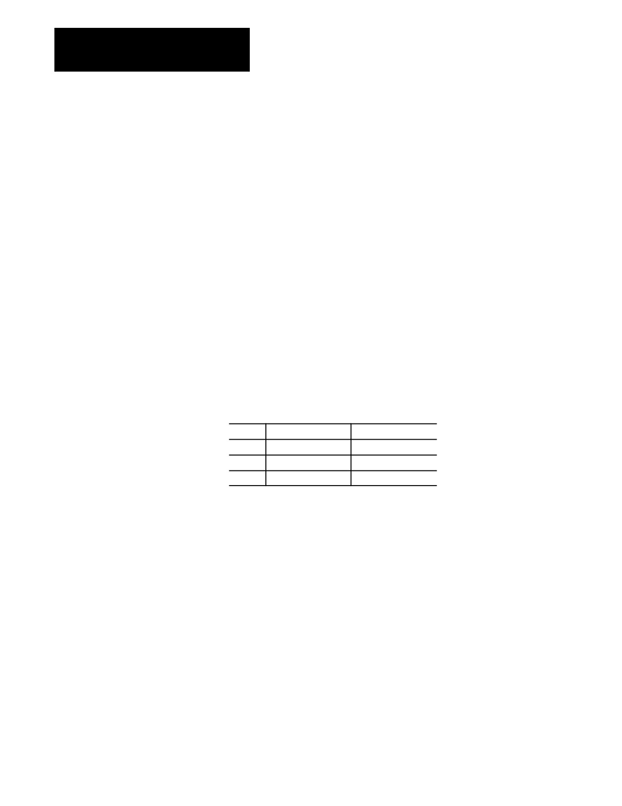
disabled by programming an L-word with the M-code. There are 4
L-words:
L0
Interrupt type 1
Switch 0 triggers this
L1
Interrupt type 2
Switch 1 triggers this
L2
Interrupt type 2
Switch 2 triggers this.
L3
Interrupt type 2
Switch 3 triggers this
Program these L-words in each M96 or M97 block. Not programming the
L-word causes the control to assume an L-word of L0 has been
programmed. Refer to documentation prepared by the system installer for
the location and operation of the 4 switches.
If more than one L-word is programmed in a block, the right-most L-word
is the one that is used for that block. Other L-words in that block are
ignored.
Selecting an Interrupt Program
Any legal subprogram or paramacro may be selected as a interrupt
program (see chapter 10 on subprograms or chapter 28 for paramacros).
For a program to be used as an interrupt program it must have a program
name of 5 numeric characters following an O address (see chapter 10 on
program names). This interrupt program must contain an M99 block as the
last block in the interrupt program. This M99 block has all of the same
restrictions as an M99 block for a subprogram as described in chapter 10.
29-2
Chapter 29
Program Interrupt
The subprogram or paramacro program is assigned to a particular type of
interrupt by programming a P-word in the M block that enables the
interrupt (M96 in this manual). When selecting a program with a P-word,
only the numeric value of the program name is entered; the letter O is
omitted. For example, programming:
M96L0P11111;
would enable the program O11111 as a type 1 interrupt and allow it to be
executed when switch 0 sends a signal to PAL. If the program called with
the P-word does not exist, the control will generate an error when the
switch that activates the program is activated. The P-word is not
programmed in the disable M-code block (M97 in this manual).
Example 29.1
Enabling and Disabling the Interrupt Features
N1M96L0P11111;
Enables program O11111 as a type 1 interrupt and
allows it to be executed when the interrupt
signal from switch 0 is received.
N2M96L1P12345;
Enables program O12345 as a type 2 interrupt and
allows it to be executed when the interrupt
signal from switch 1 is received.
N3M96L3P11111;
Enables program O11111 as a type 2 interrupt and
allows it to be executed when the interrupt
signal from switch 3 is received. This is the
same program as selected for type 0 interrupts.
N4M97L3;
Disables any interrupt program that is called by
switch 3. Any signal to execute an interrupt
from switch 3 is ignored after this block is
executed unless reactivated with a M96L3 block.
N5M96L0P22222;
Alters the program that is called for the
interrupt with switch 0. The new program called
when the interrupt signal is received is O22222.
N6M97L0;
Disables interrupt switch 0.
N7M97L1;
Disables interrupt switch 1.
Important: All program interrupts that are enabled in a part program are
automatically disabled by the control when:
an end of program (M02 or M30) block is read
a new program is selected as active
a control reset is performed
29-3

Chapter 29
Program Interrupt
29.2
Interrupt Request
The system installer determines:
Considerations
- in AMP, if a signal to execute an interrupt program is delayed
until the end of a currently executing block, or executed
immediately.
- in AMP, whether an interrupt program request is recognized
when an interrupt switch is turned on, or only when the switch
makes the transition from off to on. This helps prevent the
accidental execution of an interrupt program.
- whether to write PAL to allow the use of 4 interrupt signals (4
switches). One of these signals can call a type 1 interrupt; the
other three call a type 2 interrupt.
Interrupt programs:
- should normally be disabled during thread cutting. The execution of
an interrupt program during a threading pass can cause undesired
results.
- can only be executed when the control is in the automatic mode.
Interrupt requests that occur during MDI or manual modes are
ignored.
Consider tool tip radius compensation during an interrupt request:
Compensation
The Status Remains:
Status:
Active (G41 or G42)
Active throughout execution of the interrupt unless canceled
with a G40. Different tool radii (selected with a T-word) and
different compensation directions (G41 or G42) can be
programmed in the interrupt program. It is the programmer’s
responsibility to make sure the correct compensation direction
(G41, or G42) is active and the correct length and radius offset
is active (as programmed with the T-word) before the M99
return from interrupt command is executed.
Not Active
Can be activated by programming either a G41 or G42 in the
interrupt program. Compensation must be turned off with a
G40 in the interrupt program before the M99 return block is
executed.
29-4

Chapter 29
Program Interrupt
An Interrupt:
- requested when the control is in E-Stop is ignored, regardless of
whether the interrupt is enabled or not.
- can only be executed when the control is in the <CYCLE START> state.
If a request for an interrupt is made when the control is in
<CYCLE STOP> or cycle suspend, the interrupt request is still
recognized. The interrupt program will be executed when a
<CYCLE START> state becomes active again.
- are recognized after it has been enabled by programming a M96
followed by the correct L-word for that signal.
If an interrupt occurs during a block retrace, the interrupt will be
performed. The block retrace however will be aborted at that point and
no further retrace will be allowed. Block retrace will, however, still be
able to return any moves that have already been retraced before the
interrupt occurred.
During the execution of a milling cycle, if the interrupt is a delay type
(executed at the completion of the currently executing block), the
control will execute the interrupt after all motions generated by that
block are completed. If the interrupt type is immediate (executed as
soon as the interrupt signal is received), the control interrupts the
currently executing path.
29.3
There are two types of interrupts, type 1 and type 2. These are selected by
Interrupt Types
the L-word in the M96 block.
This L-word:
Actives This Interrupt:
Shown in:
L0
Type 1
Figure 29.1
L1
Type 2
Figure 29.2
L2
Type 2
Figure 29.2
L3
Type 2
Figure 29.2
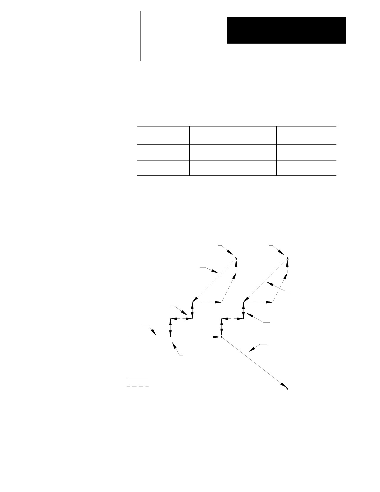
The key difference between a type 1 and a type 2 interrupt is the tool path
that is taken when the return from interrupt is made as programmed with
an M99 in the interrupt program.
29-5
Chapter 29
Program Interrupt
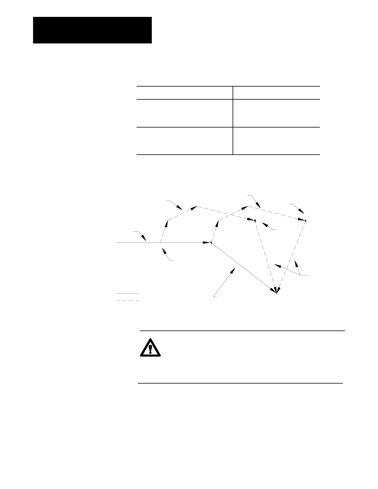
Type 1 Interrupts
If the Interrupt Program:
Then the Control:
Does not generate axis motion
executes the interrupt program and then
continues executing the part program as
normal regardless of the location that
the interrupt program was executed.
Generates axis motion
returns the tool to the endpoint of the
next fully unexecuted block and
continues executing the part program
from this point.
Figure 29.1
Type 1 Interrupt
Motions due to
Motions due to
Immediate Action
Delayed interrupt
interrupt
M99
Part program
path before
interrupt
M99
Interrupt
occurs
Return path
Programmed Path
This block is not
Path of Interrupt
executed unless there
are no motion commands
in the interrupt
CAUTION: If the interrupt is executed in the middle of a
block’s execution, and there is axis motion in the interrupt
program then the control will never reach the end point of the
interrupted block. Execution will transfer to the end point of
the following block. This applies to type 1 interrupts only.
29-6
Chapter 29
Program Interrupt
Type 2 Interrupts
The control returns the tool to the point in the program where it was when
the interrupt was performed by using type 2 interrupts. Normally the first
4 linear moves (G00 or G01) in the interrupt program are remembered.
This may be altered by programming a specific M-code.
If You Perform:
As:
Then: the Control
Remembers:
A non-linear (G02 or
One of the first 4 blocks of the interrupt
The moves up to that
G03) circular move
block
A non-linear (G02 or
The first block in the interrupt
The start point of that
G03) circular move
block
These remembered blocks are retraced after the M99 code is read by the
control in the interrupt program. This returns the cutting tool to the
location in the program where program execution was interrupted.
Figure 29.2
Type 2 Interrupt
M99
M99
Return path
Motions due to
Return path
Immediate Action
interrupt
Part program
path before
Motions due to
interrupt
Delayed interrupt
This block is not
executed unless there
Interrupt
are no motion commands
occurs
in the interrupt
Programmed Path
Path of Interrupt
29-7
Chapter 29
Program Interrupt
You can alter the number of blocks that the control re-executes in reverse
when returning to the start position of the interrupt. The number of return
blocks is normally 4; however, it can be altered by these codes:
M-code:
Number of
Blocks Retraced:
M900
zero
M901
one
M902
two
M903
three
M904
four
These M-codes can be programmed in any block in the main program
before the interrupt program is executed. They can also be programmed
within an interrupt though the M-code will not go into effect until
execution is returned to the main program. If not programmed, the default
is 4 blocks. The default is automatically reset at the end of program
commands (M02 or M30).
The number of retrace blocks set with this M-code is the same for all
active or inactive interrupts. If an interrupt is enabled after this M-code is
programmed, it takes on the number of retrace blocks as programmed with
this M-code.
When the return from interrupt is executed (M99 in the interrupt), the
control generates a linear move to the end point of the last remembered
move for retrace. Then the moves are retraced, returning the tool to the
start point of the interrupt. This may not be the same location in the main
program if a different tool offset has been activated.
29.4
When you intend to use a program as an interrupt program, remember:
The Interrupt Program
Any modal data (G-codes, feedrates, spindle speeds, coordinate system
offsets, etc.) contained in the main program are carried into the interrupt
program. Any changes made to this modal data within the interrupt will
be effective only in the interrupt program; changes are not carried back
into the main program when the interrupt is completed. This does not
include tool or tool offset data that is changed in the interrupt. Any tool
or tool offset changes will be carried back into the suspended main part
program.
29-8
Chapter 29
Program Interrupt
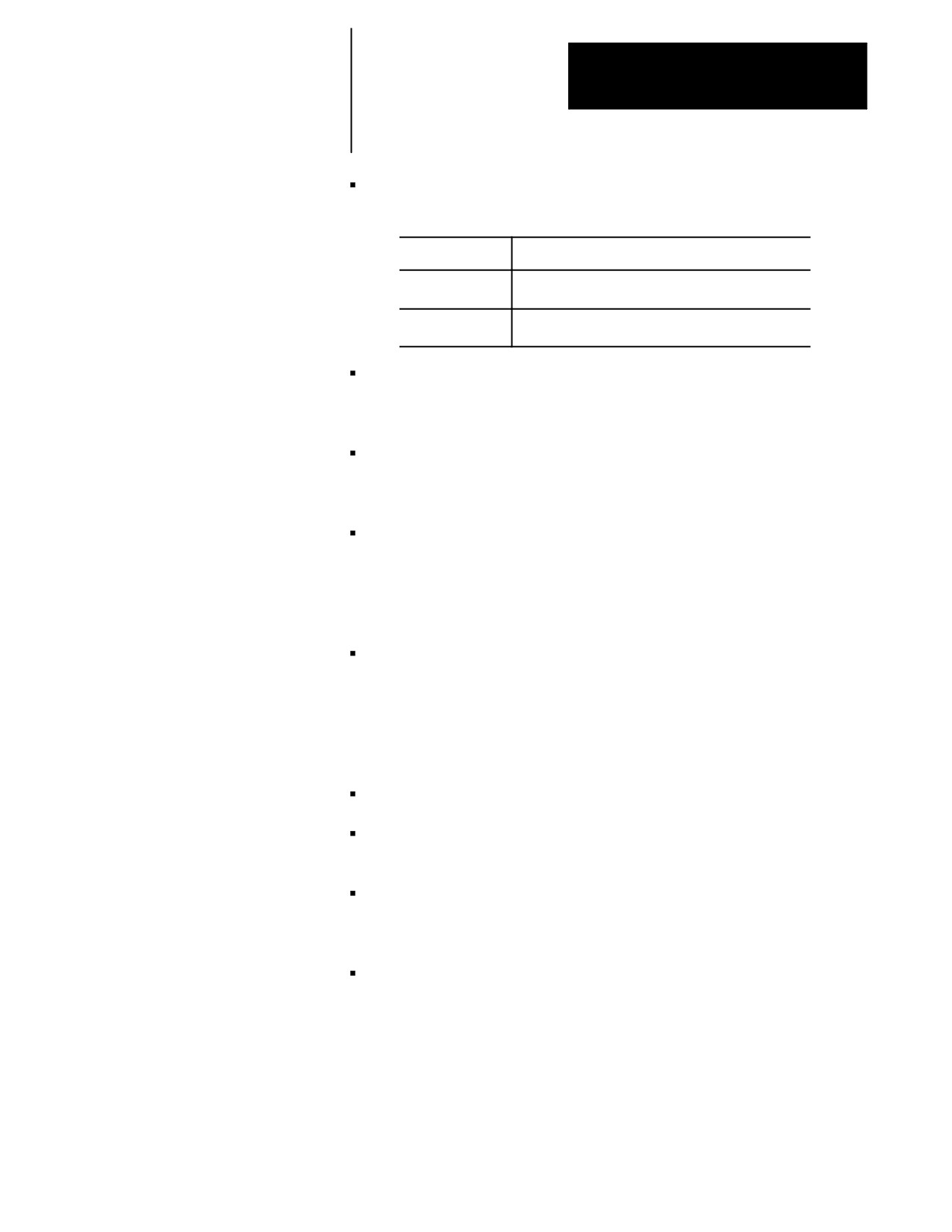
The system installer determines if an interrupt program is to be called as
a paramacro or a subprogram when it executes.
If it is Called:
Then:
A Paramacro
This assigns a new set of local parameters for the
interrupt
A Subprogram
The same set of local parameters that applied to the
interrupted program apply to the subprogram.
If an interrupt is chosen as a macro program, it may not be a macro that
requires the assignment of local variables in the calling block (cannot
require an argument).
Macro type interrupts are always called as the G65 non-modal type.
G66 and G66.1 modal types may not be called. Refer to the chapter on
paramacros for details on the G65 type macros.
The interrupt program must contain an M99 block. Any axis motion
commands that are to the left of the M99 code in the block will result as
an error. Other programming commands to the left of the M99 code in
the block will be executed. Any characters to the right of the M99 code
in the block are ignored.
If using a type 2 interrupt (L1, L2, or L3), remember that the control
remembers as many as the first 4 blocks in the program and uses these
to retrace its moves back to the starting point of the interrupt program.
The control remembers as many as 4 of the first moves or until a
circular block is executed. For details, see section 29.3 on interrupt
types.
The interrupt program may contain a milling cycle in the interrupt.
Coordinate system offsets are illegal in an interrupt program. This
includes G52, G92, G92.1, and G92.2.
Any inherent modality from the main program (such as a milling cycle,
or an active modal paramacro) will be temporarily canceled during the
execution of a interrupt program.
Although all four interrupts can be active at once, only one interrupt can
be executing at any given time.
END OF CHAPTER
29-9

Chapter
30
Using a 9/Series Dual-Processing System
30.0
Read this chapter to learn general information related to programming and
operating a dual-processing system. Major topics in this chapter cover:
Chapter Overview
Topic:
On page:
Definition of a dual-processing system
30-1
Operating a dual-processing system
30-2
Synchronizing multiple part programs
30-7
Spindle control for dual-processing
30-12
Using interference checking
30-19
30.1
A dual-processing system is basically two machine tools in one. One
Defining of a
9/Series control is capable of executing two separate part programs,
controlling separate machining axes. Offsets, tool management, axis
Dual-Processing System
feedrate are independent for each program. Each of these two
independent systems is called a process. The 9/Series control is capable of
running two processes simultaneously.
You can configure the 9/Series dual-processing lathe to run on a wide
variety of machines. For dual-processing to function correctly, your
system installer must make certain AMP and PAL configuration
considerations. Refer to the 9/Series CNC AMP and PAL Reference
Manuals or your system installer’s documentation for details.
This chapter focuses on a 4-axis lathe, sometimes called a dual-turret lathe.
Many other applications, like a completely separate twin-turning machine
or a dual-spindle lathe are possible and easily configured by your system
installer. Operation of these other applications must be interpreted from
the dual-turret application presented in this manual.
Your system installer selects the lathe G-code system your dual-process
lathe is using. Both processes must use the same G-code system. Refer to
your system installer’s documentation for details.
30-1
Chapter 30
Using a 9/Series Dual--Processing System
30.2
Dual-process systems operate almost exactly the same as their
single-process counterparts. Each process functions as an independent
Operating a
9/Series control.
Dual-Processing System
With the exception of shared dual-processing paramacro parameters, there
is little shared data between processes. Each process has its own offset
tables, programmable zone tables, and paramacro parameters. Your system
installer:
determines how your system operates in PAL. For example, pressing
<CYCLE START> could be written in PAL to start both processes, start the
selected active process, or separate <CYCLE START> buttons could be
installed for each process. Most operations can be duplicated on a per
process basis.
establishes priorities for your processes in AMP. The priority of a
process determines how much time the control spends executing blocks
in one process relative to another process. Your system can be set up to
give one process almost exclusive use of the control’s time with the
other process executing only when time becomes available. Refer to
your system installer’s documentation for more information on the
priority configuration in your system.
Selecting the Active Process
When you operate a 9/Series dual-process system, multiple processes exist
that are usually controlled by the same MTB and operator panels. Your
system installer can install separate MTB panels for each process on some
machines. An active process must be selected to determine which process
is currently being controlled by the operator panel. The line immediately
above the softkey names on the CRT indicates which process is currently
active. The currently active process appears in reverse video on that line.
When you operate a 9/Series dual-process system, multiple processes exist
that are usually controlled by the same MTB and operator panels. Your
system installer can install separate MTB panels for each process on some
machines. An active process must be selected to determine which process
is currently being controlled by the operator panel or MTB panel. The line
immediately above the softkey names on the CRT indicates which process
is currently active. The currently active process appears in reverse video
on that line.
30-2

Chapter 30
Using a 9/Series Dual--Processing System
You cannot switch the active process while you use the digitize feature, a
tool path or QuickCheck graphic display, or within an active program
search operation. If you attempt to switch the active process, the control
displays an error message. Select an active process by using one of these
methods:
Method:
Description:
[PROC SELECT] key
found on the operator panel next to the [TRANSMIT] key.
Each time you press the [PROC SELECT] key, the
currently active process changes as shown on the CRT.
System installer
s key
your system installer can control which process is active at a
given time through PAL. Refer to your system installer
s
documentation for details on the location and operation of this
feature.
[SHIFT] key & {fi } softkey
you can toggle between processes each time you press these
on the end of the softkey rack
keys. This functions identically to the [PROC SELECT]
key.
All functions performed on the operator panel (this includes softkey
functions), and position displays (except for split-screens) are
representative of the currently active process. On split-screens, the CRT
display shows position displays and process information for both
processes.
Split-Screen Displays
All of the 9/Series position display screens are available as split-screens.
A split-screen is a screen that shows both processes at the same time on the
CRT, regardless of which process is active. Refer to page 8-21 for details
on using the split-screen feature.
The Part Program Directory
Both processes share the system’s part program directory. They both have
access to the same programs. They can be activated from both processes.
The system directory shows which process has programs active or being
edited at any given time. An “A1” or “A2” next to the program name
shows which process currently has the program active. An “A12” next to
the program name shows the program is currently active in both process 1
and process 2.
If you execute a part program from a tape reader, each process must have
its own tape reader. However, you can use one tape reader if you load the
part program into memory for one process.
30-3
Chapter 30
Using a 9/Series Dual--Processing System
Editing a Part Program
An “E” next to the program name on the part program directory screen
indicates that the program is currently being edited. Only one program can
be open for editing at a time. You cannot edit programs in more than one
process at the same time.
You cannot edit a program that is currently active (selected to run) in a
different process. If a program is active in one process and you select
process 2 and attempt to edit the active program in process 1, the control
displays an error.
If the same program is active in both processes, you cannot edit the
program unless you deactivate it in one of the processes.
QuickView prompts are available when you write your program (see page
5-16). These prompts help you by describing (often graphically) the
programming of different operations on the 9/Series control. QuickView is
available only to one process at a time. QuickView cannot be activated if
either process currently has either QuickCheck Graphics or Active
Program Graphics turned on.
QuickView does not necessarily prompt you for the currently active
process selected on the control. Independent QuickView process-select
softkeys let you select a process for programming. Changing the process
with this key only changes the axes names and displays to the newly
selected process for QuickView’s prompting. It does not change the actual
currently active process on the control.
When you have a dual-process lathe, additional softkeys on QuickView
softkey level 4 are available. These softkeys are named after each of the
process names. The currently selected process for QuickView prompts
will have its softkey shown in reverse video. You must still select a plane
for each process for the QuickView feature as described in chapter 5.
Graphics
Active graphics or QuickCheck graphics can be active in only one process
at a time. You cannot switch from graphic to graphic without disabling
graphics in one process and then moving into the other process.
When you plot the path of a shared axis on a graphics screen the modality
of the process running graphics determines the line type being plotted
(rapid or cutting move). For example if the X axis is shared and is
performing a rapid move in process two, and graphics is running in process
1, process one’s current mode determines if the graphics display shows a
dashed rapid or a solid cutting line. The actual axis speed is not affected
by the graphics plot line type.
30-4
Chapter 30
Using a 9/Series Dual--Processing System
You can use QuickCheck as a program “syntax only” checker
(no graphics) in both processes at the same time.
Error Messages
The control displays error messages on the screen for only the currently
active process (except on split-screens). The name of the currently active
process flashes in reverse video if an error occurs in another process.
Change to the appropriate process to display the current errors for that
process.
On a split-screen display, the control displays the full error messages for
both processes, regardless of which process is currently active.
The control keeps separate error message logs for each process. The error
logs list the errors in sequential order.
Refer to page NO TAG for more details on error messages.
Single-Digit Feedrates
Both processes share one table of single-digit feedrates. The control looks
to the single-digit feedrate table when it encounters a single-digit F-word
during block execution. The feedrate in this table that corresponds to the
single digit becomes the active feedrate. You cannot define different
single-digit feedrate tables for each process.
The rapids for each individual--axis determine the feedrate used for F0.
Your system installer determines the rapid for each axes.
Refer to page 3-23 for information on single-digit feedrates.
30-5

Chapter 30
Using a 9/Series Dual--Processing System
Reset Operations
Dual-process systems have a process reset operation, in addition to the
normal block reset and control reset functions. These reset operations
work as follows:
If you want to
Press:
The control will:
perform a:
Block Reset
[RESET]
Skip the currently active block in the
currently selected process
(see chapter 2).
Control Reset
[SHIFT] + [RESET]
Return the control to the default settings,
clear any program errors, and cancel
MDI commands in all processes
(see chapter 2).
Process Reset
[SHIFT] +
Return the program of the currently
[PROC SELECT]
selected process to the first block. Does
not affect the additional processes (only
works on programs executed from
control memory).
¶ If only one (or both) processes are still executing their part program when a control
reset is performed, only processes not currently executing a part program will have a control
reset performed. A message will occur in the processes executing the program stating that a
control reset is not allowed on that process.
Communication Between Processes (Shared Paramacro Parameters)
A link between the different processes of the machine is provided with the
dual-process shared paramacro parameters. These parameters are available
only on dual-process lathe systems. They provide a link through which
common data can be passed between the different part programs executing
in the different processes of the machine. The shared dual-process
parameters are paramacro parameter numbers:
#7100 to #7199
Refer to page 28-33 for details on these paramacro parameters.
30-6

Chapter 30
Using a 9/Series Dual--Processing System
30.3
On some machines or systems, it is often necessary to synchronize the
operations of 9/Series dual processes. For example, on a dual-turret lathe,
Synchronizing Multiple Part
if one turret must rough a shaft down to size before another turret begins
Programs
cutting a thread, it is extremely important that the turret roughing the shaft
completes this task before the threading turret begins cutting the thread.
Figure 30.3
Example of When Process Synchronization is Necessary
First process must rough down stock before second process can
start cutting threads.
Process 2
Threading
Process 1
12598-I
Roughing
Part program synchronization is accomplished between processes through
the use of special M-codes. These M-codes are in group 13, and they are
non-modal. The M-codes reserved for synchronization are M100 - M199.
When you execute a synchronization M-code in one process, that process
halts until a block containing the same synchronization M-code is executed
in the second process. In the case of the threading example on page 30-7,
placing one of these M-codes before the threading block and after the
roughing block causes the threading block to pause (not execute) until the
roughing block has completed.
These synchronization M-codes cannot be programmed in a block with
other commands. The only other types of information you can program in
a synchronization block are:
N-codes (block number)
O-words (program name)
Program comments (text enclosed by parentheses () )
30-7

Chapter 30
Using a 9/Series Dual--Processing System
Synchronization M-codes are not allowed in the last block in the part
program. This can cause the part program to pause indefinitely, waiting
for the next part program block (which does not exist) to become active.
Synchronization M-codes are ignored during QuickCheck execution and
during a Mid-Program Start operation.
Example 30.1
Example of Synchronization for Threading (see Figure 30.3)
Process 1
Comment
Process 2
Comment
N1 G90 S500 G00 X40. Z60.;
Start spindle and move to start point
N1 G90 G00 X40. Z60.;
Move to threading cycle start point
N2 G20 X28. Z25. F10.;
Start roughing shaft
N2 M100;
Wait for roughing to complete (process 1
block N5)
N3 X24.;
Roughing shaft
N4 X20.;
Roughing shaft
N5 M100;
Release process 2 block N2
N3 G21 F.5 X19. Z26.;
Start threading shaft
N6 M30;
N4 X18.;
Threading shaft
N5 X17.;
Threading shaft
N6 X16.;
Threading shaft
N7 M30;
Simple Synchronization vs Synchronization with Setup
There are two types of synchronization M-codes. They are:
M100 - M149 — Simple Synchronization. These M-codes are for
simple synchronization. When executed, this set of M-codes does not
set up any program blocks that have already been read into program
lookahead again.
M150 - M199 — Synchronization with Setup. This set of M-codes
cancels any information already in block lookahead and sets up the
block again before process execution is resumed. This second setup is
only essential when shared information is being changed from one
process to another, as in the case of the dual-processing shared
paramacro parameters.
Important: You cannot use synchronization with setup M--codes when
TTRC is active. Use one of the simple synchronization M--codes or turn
off TTRC before programming the synchronization with setup M--code.
30-8
Chapter 30
Using a 9/Series Dual--Processing System
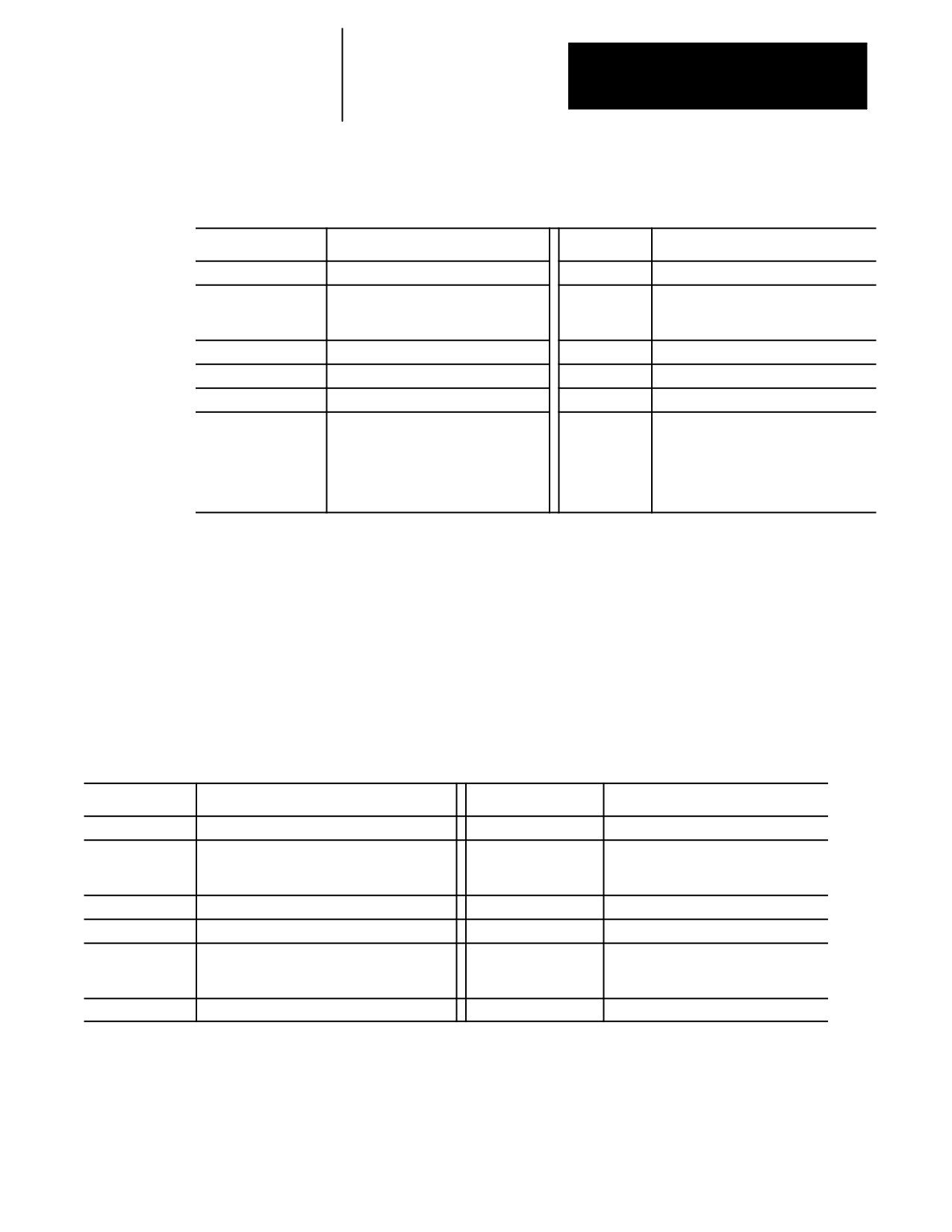
Example 30.2
Incorrect Use of Simple Synchronization with Shared Paramacro
Parameters
Process 1
Comment
Process 2
Comment
N17 #7100=100;
Paramacro parameter 7100 is set to 100
N32 M100;
Process pauses waiting for M100 in
process 1. Block N33 is set up in buffer
prepared for execution.
N18 Z#7100;
N19 #7100=25
Paramacro parameter 7100 is set to 25
N20 M100;
Process 2 is released from pause
N33 X#7100;
Destination of this block is dependent on
when this block was read into the setup
buffer. If this block was set up before
process 1 executed block N19, X moves
to 100. If this block was set up after
block N19 is executed, X moves to 25.
Since there is no way to consistently tell when block N33 in Example 30.2
is set up, an inconsistent destination for the block can result. When block
N33 is set up, depends on many factors, like what features you are
currently using, the speed of execution, and complexity of blocks in both
processes (see block lookahead in chapter 21 for details). To make certain
that block N33 is not set up until process 1 releases process 2, use one of
the synchronization-with-setup M-codes.
Example 30.3
Correct Use of Synchronization with Set up for Shared Paramacro
Parameters
Process 1
Comment
Process 2
Comment
N17 #7100=100;
Paramacro parameter 7100 is set to 100
N32 M151;
Process pauses, waiting for M151 in
process 1. Block N33 is setup in buffer
prepared for execution.
N18 Z#7100;
N19 #7100=25
Paramacro parameter 7100 is set to 25
N20 M151;
Process 2 is released from pause and any setup
buffer read into process 2 block lookahead is
purged and set up again.
N33 X#7100;
X axis moves to 25.
You can use synchronization-with-setup any time synchronization is
necessary, but it does have some cost to system efficiency and can slow
your system down. We recommend that you use M150 -- M199 only when
you change shared paramacro parameters. For most applications, simple
synchronization (M100-M149) is sufficient.
30-9
Chapter 30
Using a 9/Series Dual--Processing System
Coordinating Synchronization Between Processes
Remember that both processes are executing coordinated part programs.
Failing to coordinate part programs correctly can result in the processes
executing different synchronization codes and mutually locking each other
out.
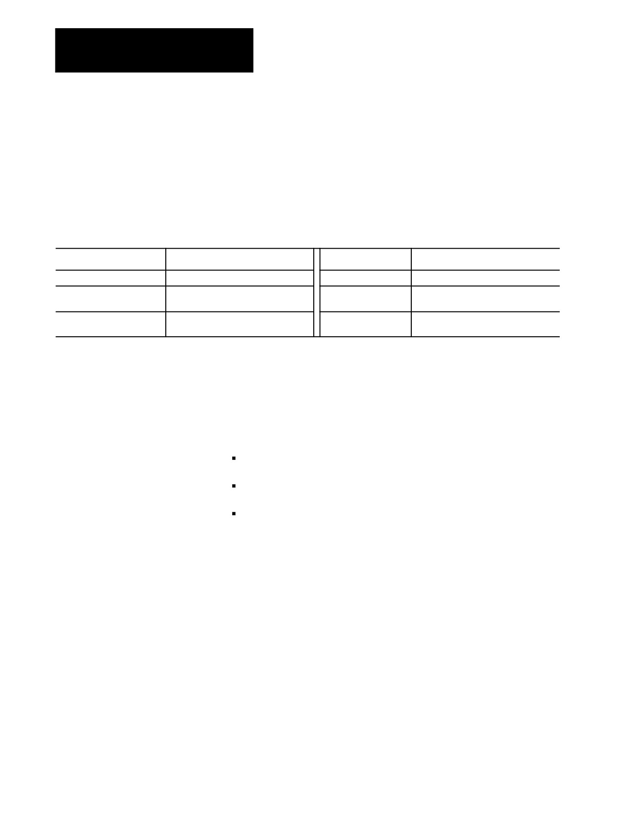
Example 30.4
Mismatched Synchronization Codes
Process 1
Comment
Process 2
Comment
N7 #7100=25;
N32 M101
Process 2 paused, waiting for M101 in
process 1.
N8 M100
Process 1 paused, waiting for M100 in
process 2.
In Example 30.4, both processes are paused indefinitely, waiting for the
other process to execute the corresponding M-code. The control displays
an error message when this situation occurs, indicating that execution of
that block has been suspended until it synchronizes with the other process.
Perform a Block Reset to allow part program execution to continue.
You can help prevent this situation by:
being consistent and always start your programs with the same
synchronization M-codes
making certain each program contains the same number of
synchronization M-codes
making sure the synchronization M-codes are placed in the same
corresponding order between processes
30-10