9/Series CNC Lathe. Operation and Programming Manual - page 27
Chapter 30
Using a 9/Series Dual--Processing System
An axis that is decoupled from its dual group can have an integrand letter
assigned to it in AMP by the system installer. This integrand is used with
that axes originally assigned AMP axis name to perform functions such as
circular interpolation. Plane dependant operations (such as circular
interpolation or cutter compensation) are available to a dual axes while
coupled (provided the dual--axis is defined in the active plane). Once
decoupled these plane dependant functions are available to the members of
a dual group as independent axes (provide that the axis is used in the active
plane). Planes can contain dual axes from within the same dual group
however these planes are only available when the dual--axis group is
decoupled and in the process that is currently activating the plane.
Dual Drilling Axis
If the slave of a dual--axis is AMPed as the fixed drilling axis, the entire
dual group operates as a drilling axis when coupled. Once decoupled
however the drilling axis traits are independent for each axis. The system
installer determines which axes are drilling axes in AMP. For example
your control has a dual--axis made up of X1, X2, and X3. The system
installer has AMPed X2 to be the fixed drilling axis. When coupled the X
axis is programmed as a drilling axis. When decoupled only the X2 axis is
programmed as the drilling axis (note X2 when decoupled uses its AMP
defined axis name, not X2).
END OF CHAPTER
30-41
Appendix
A
Softkey Tree
Appendix Overview
This appendix explains softkeys and includes maps of the softkey trees.
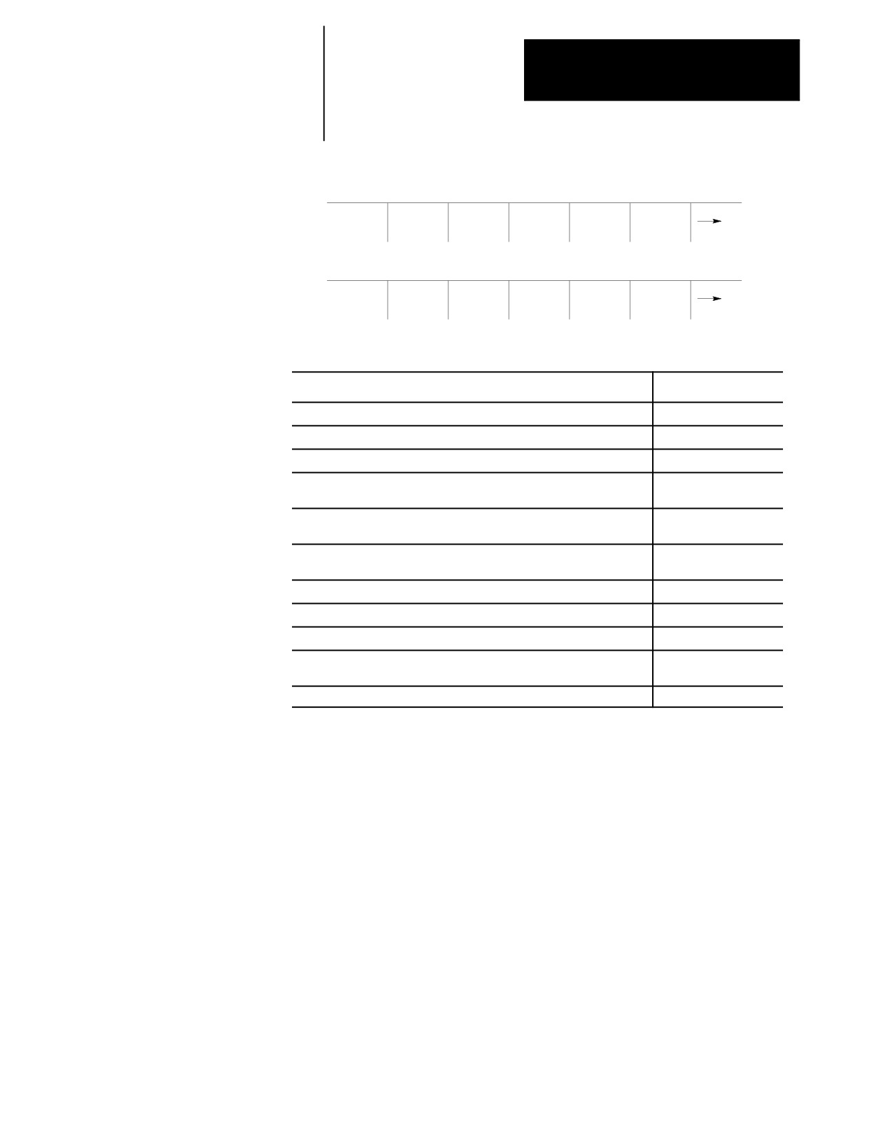
We use the term softkey to describe the row of 7 keys at the bottom of the
Understanding Softkeys
CRT. The function of each softkey is displayed on the CRT directly above
the softkey. Softkey names are shown in this manual between the { }
symbols.
Softkeys are often described in this manual as being on a certain level, for
example, softkey level 3. We use the level of the softkey to determine the
location or necessary path to reach that particular softkey function. For
example, to get to a softkey on level 3, you must press a specific softkey
on level 1 followed by a specific softkey on level 2.
Specific softkeys for all levels change depending on the previous softkey
pressed, with the exception of softkey level 1, which always remains the
same. Softkey levels are all referenced from softkey level 1.
The softkeys on opposite ends of the softkey row have a specific use that
remains standard throughout the different softkey levels. On the left is the
exit softkey displayed with the up arrow {›} and on the right is the
continue softkey displayed with the right arrow {fi }.
Use the exit softkey {›} on the far left to regress softkey levels. For
example, if you are currently on softkey level 3 and you press the exit
softkey, the softkeys change to the softkeys previously displayed on
softkey level 2. When you press the exit softkey while holding down
the [SHIFT] key, the softkey display returns to softkey level 1 regardless
of the current softkey level.
When more than 5 softkey functions are available on the same level, the
control activates the continue {fi } softkey at the far right of the softkey
area. When you press the continue softkey, the softkey functions
change to the next set of softkeys on that level.
The continue softkey is not available if there are 5 or fewer softkey
functions on that level.
A-1
Appendix A
Softkey Tree
For example :
(softkey level 1)
PRGRAM
OFFSET
MACRO
PRGRAM
SYSTEM
MANAGE
PARAM
CHECK
SUPORT
When softkey level 1 is reached, the previous set of softkeys is displayed.
Press the continue softkey {fi } to display the remaining softkey functions
on softkey level 1.
(softkey level 1)
FRONT
ERROR
PASS-
SWITCH
PANEL
MESAGE
WORD
LANG
On softkey level 1, the exit softkey is not displayed since the softkeys are
already on softkey level 1.
The softkey functions for level 1 softkeys are explained in this appendix.
Softkey functions for level 2 or higher are explained in the sections that
apply to specific operations. A “tree” of softkeys listing all the softkeys
and their levels is included in the back of this appendix.
Important: Some of the softkey functions are purchased as optional
features. This manual assumes that all available optional features have
been purchased for the machine. If the feature has not been purchased,
blank keys may appear.
A-2
Appendix A
Softkey Tree
(softkey level 1)
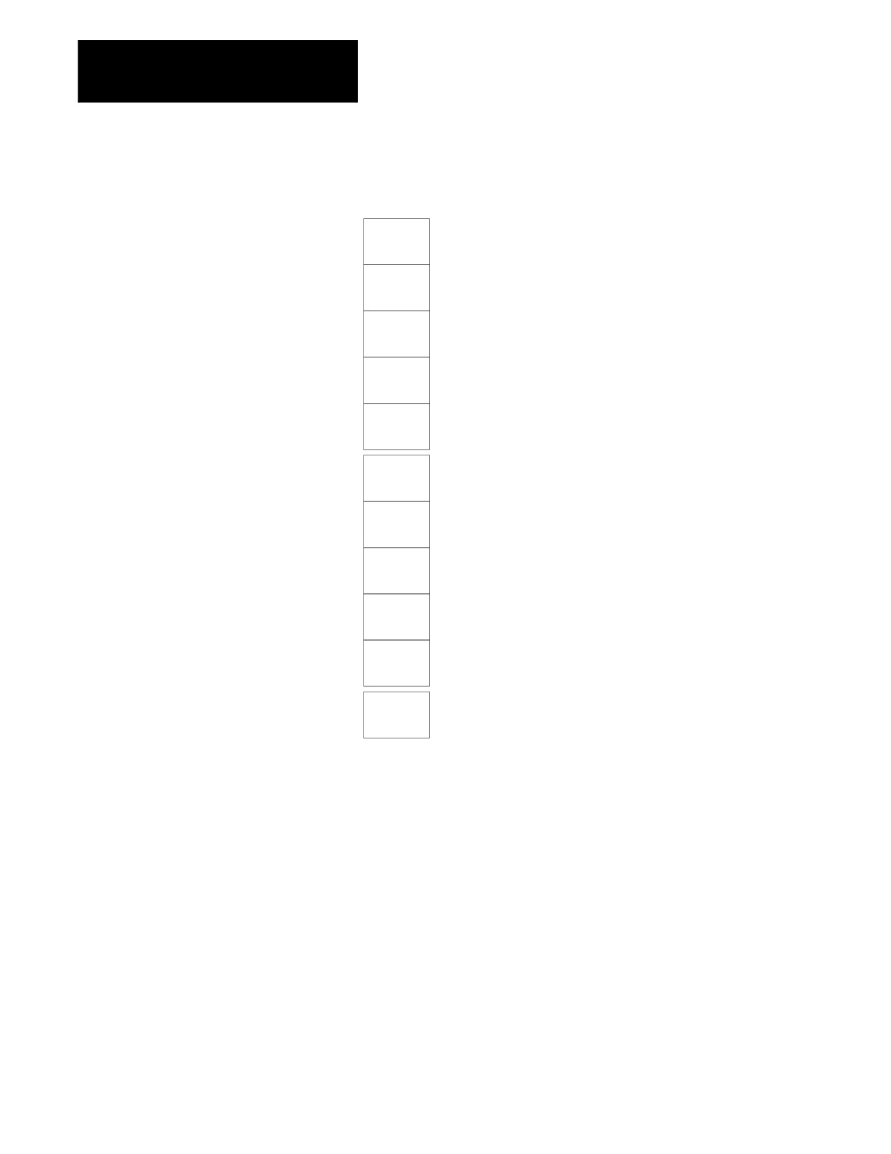
Describing Level 1 Softkeys
PRGRAM
OFFSET
MACRO
PRGRAM
SYSTEM
MANAGE
PARAM
CHECK
SUPORT
FRONT
ERROR
PASS-
SWITCH
PANEL
MESAGE
WORD
LANG
If you want to:
Press:
Edit, activate, or copy a program from a peripheral or control memory
{PRGRAM MANAGE}
Display or enter tool offset data, the work coordinate system offset data, etc.
{OFFSET}
View and modify the local and global parameter assignments for paramacros
{MACRO PARAM}
Check the part program, graphics, QuickCheck, and active program without
{PRGRAM CHECK}
actually moving an axis
Enter and display inhibit zone limits, canned cycle parameter data,
{SYSTEM SUPORT}
communications, AMP, etc.
Perform various operations that would normally be done by using an MTB
{FRONT PANEL}
panel, cycle start, jogging, etc.
Display error messages, including an error log of old messages
{ERROR MESAGE}
Enter or assign passwords and access levels to selected features
{PASSWORD}
Change the language displayed on the screen of the control
{SWITCH LANG}
Display more softkeys on the same level when there are more softkeys on
{Æ }
a level than can be displayed at once
Display the previous level or previous row of softkeys
{}
Using the Softkey Tree
The remainder of this appendix shows the softkey tree. This tree illustrates
the entire softkey layout on the control in an easy-to-use flow-chart type
format. This flow chart has been drawn to have no 4-way intersections (no
4 lines connected at any one point). If you see what appears to be a 4-way
intersection, it is really only a crossover point for lines that do not
intersect.
A-3
Appendix A
Softkey Tree
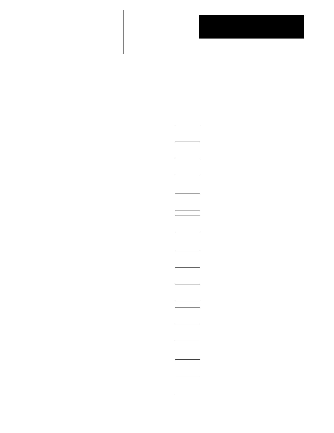
AXIS POSITION DISPLAY FORMAT SOFTKEYS
PRGRAM
A B S
NOTE: The first 4 softkeys (from PRGRAM to DTG) toggle between small
TARGET
and large screen display.
D T G
AXIS
SELECT
M CODE
STATUS
PRGRAM
D T G
A L L
G CODE
STATUS
SPLIT
ON/OFF
A-4
Appendix A
Softkey Tree
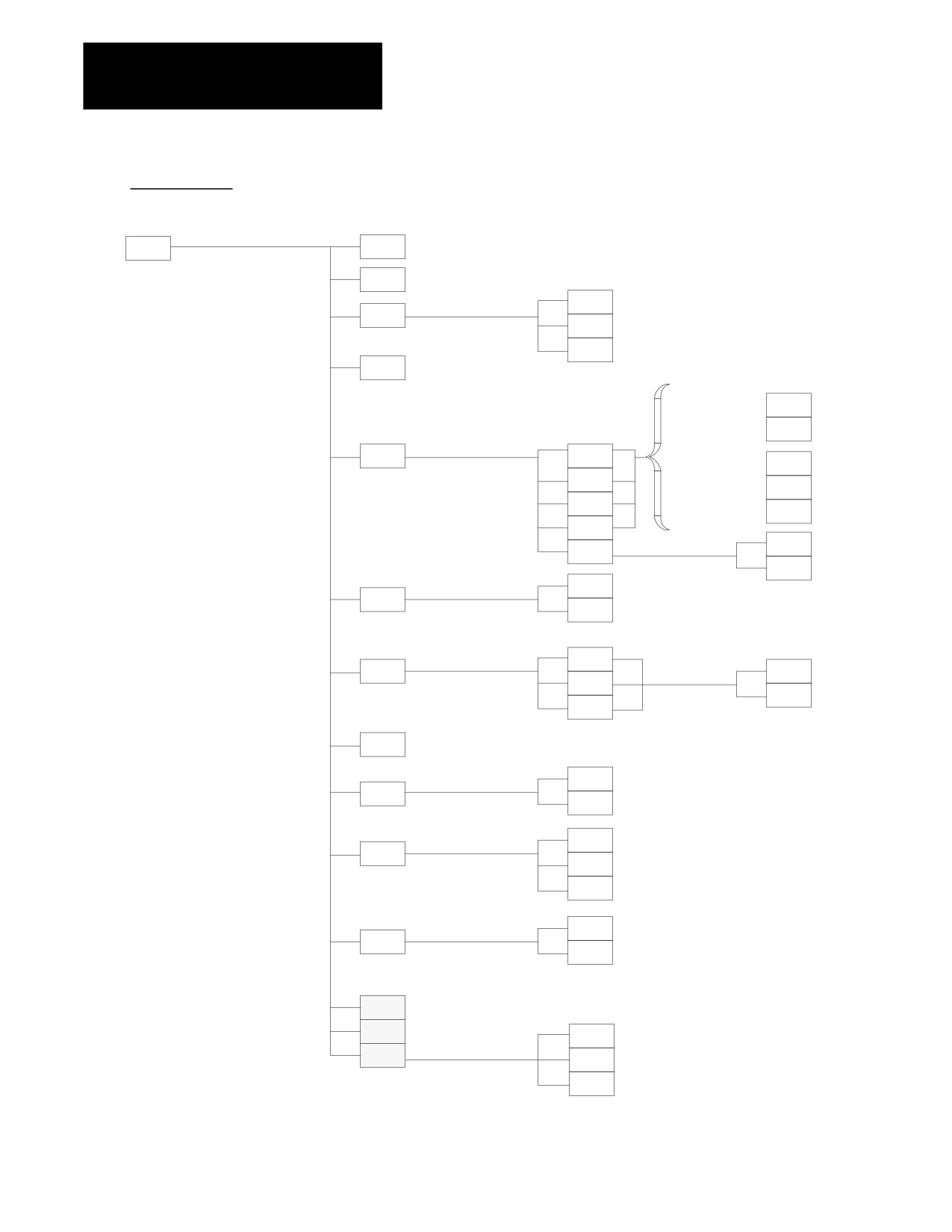
THE FUNCTION SELECT SOFTKEYS LEVEL 1
WITH POWER UP (AXIS POSITION) DISPLAY SCREEN
PRGRAM
see page A-6
MANAGE
OFFSET
see page A-7
MACRO
see page A-9
PARAM
PRGRAM
see page A-10
CHECK
SYSTEM
see page A--11
SUPORT
Optional PAL flag set to display “front panel”
FRONT
see page A-13
when MTB is not part of the total CNC system
PANEL
ERROR
MESAGE
see page A-13
PASS-
WORD
see page A-14
SWITCH
LANG
PAL Display Page Option: Five softkeys available on third
screen. Five additional softkeys can be programmed on
[PROGRAM MANAGE], [SYSTEM SUPORT], and [OFFSET]
softkey levels. This feature allows for a total of 20 additional
softkeys to be used for PAL displays.
A-5
Appendix A
Softkey Tree
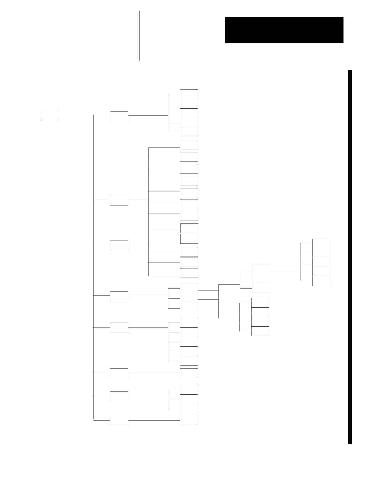
PRGRAM MANAGE
level 1
level 2
level 3
level 4
PRGRAM
ACTIVE
see page A-15
MANAGE
PRGRAM
EDIT
see page A-16
PRGRAM
EXEC
RESTRT
PRGRAM
QUIT
EXIT
DISPLY
PRGRAM
COPY
YES
The display could
COPY
be either of these
NO
sets of softkeys
COPY
MEM TO
PRGRAM
PORT A
depending on what
SINGLE
type of device you
PRGRAM
FROM A
TO MEM
have attached to
MULTI
PRGRAM
MEM TO
the control .
PORT B
OUTPUT
ALL
FROM B
TO MEM
COPY
MEM TO
YES
MEM
COPY
NO
DELETE
DELETE
YES
PRGRAM
DELETE
NO
VERIFY
VERIFY
PORT A
VERIFY
PRGRAM
VERIFY
YES
PORT B
VERIFY
VERIFY
NO
MEMORY
PRGRAM
COMENT
RENAME
YES
RENAME
PRGRAM
RENAME
NO
FROM
INPUT.
PORT A
DEVICE
FROM
PORT B
FROM
MEMORY
REFORM
YES
REFORM
MEMORY
REFORM
NO
CHANGE
These softkeys appear only if
DIR
the protectable directory is
NCRYPT
MODE
available.
UPDATE
& EXIT
SET-UP
STORE
NCRYPT
BACKUP
REVRSE
FILL
A-6
Appendix A
Softkey Tree
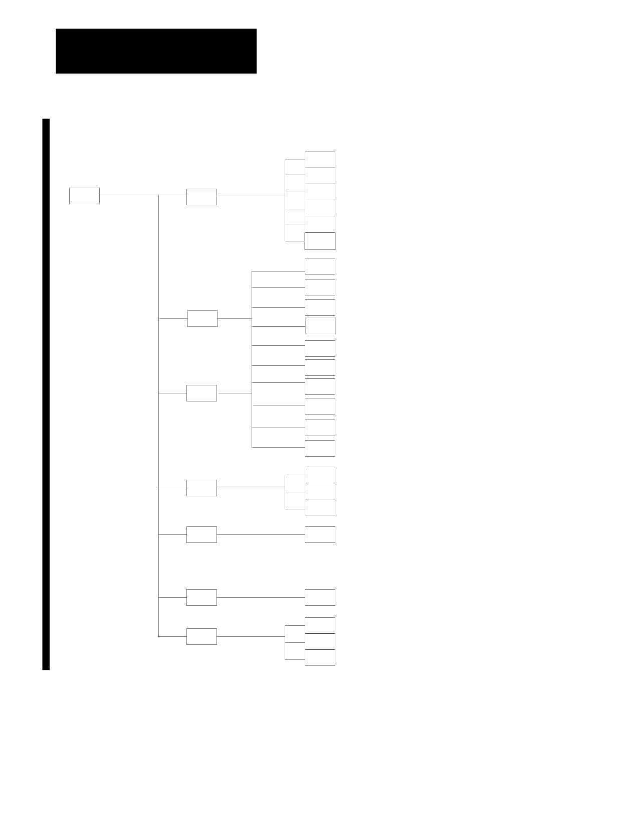
OFFSET (Lathe & Mill)
level 1
level 2
level 3
level 4
level 5
REPLCE
VALUE
ADD TO
VALUE
INCH/
OFFSET
WORK
METRIC
CO-ORD
RADI/
DIAM
(lathe only)
MORE
OFFSET
SEARCH
NUMBER
REPLCE
VALUE
ADD TO
VALUE
ACTIVE
OFFSET
MORE.
OFFSET
TOOL
WEAR
MEAS-
URE
INCH/
METRIC
NEXT
AXIS
PREV
AXIS
CHANGE
TOOL
TOOL
GEOMET
RADI/
(lathe only)
INSERT
DIAM
TOOL
DELETE
TOOL
EDIT
COPY
(lathe and mill only)
CHANGE
GROUP
TYPE
OFFSET
DELETE
CHANGE
GROUP
T RATE
TOOL
DELETE
DIR
ALL
TOOL
MANAGE
TOOL
DATA
EDT LN
BACKUP
OFF #
DATA
EDT CT
COMP #
REPLCE
EDIT
RANDOM
VALUE
LIFE
TOOL
CLEAR
RENEW
VALUE
TOOL
CUSTOM
ACTIVE
BACKUP
COORD
EXTERN
ROTATE
ON/OFF
TO
PORT A
BACKUP
OFFSET
TO
PORT B
TO
FILE
SCALING
REPLACE
VALUE
A-7
Appendix A
Softkey Tree
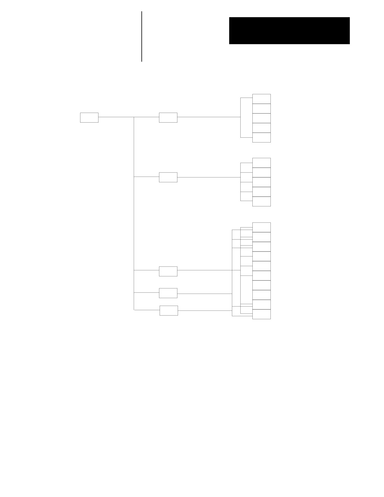
OFFSET (Grinder)
level 1
level 2
level 3
level 4
level 5
REPLCE
VALUE
ADD TO
VALUE
INCH/
OFFSET
WORK
METRIC
CO-ORD
RADI/
(cylindrical only)
DIAM
MORE
OFFSET
MODIFY
LABEL
SEARCH
NUMBER
REPLCE
VALUE
ADD TO
VALUE
WHEEL
GEOM
CHANGE
OFFSET
MORE.
OFFSET
MEAS-
(not on Radius Table)
URE
INCH/
RADIUS
METRIC
TABLE
RADI/
(not on Radius Table and cyclindrical only)
DIAM
COPY
(not on Radius Table)
OFFSET
REPLACE
VALUE
DRESSER
TABLE
ADD TO
VALUE
INCH/
METRIC
SCALING
REPLACE
VALUE
COORD
EXTERN
ROTATE
ON/OFF
TO
PORT A
BACKUP
OFFSET
TO
PORT B
TO
FILE
A-8
Appendix A
Softkey Tree
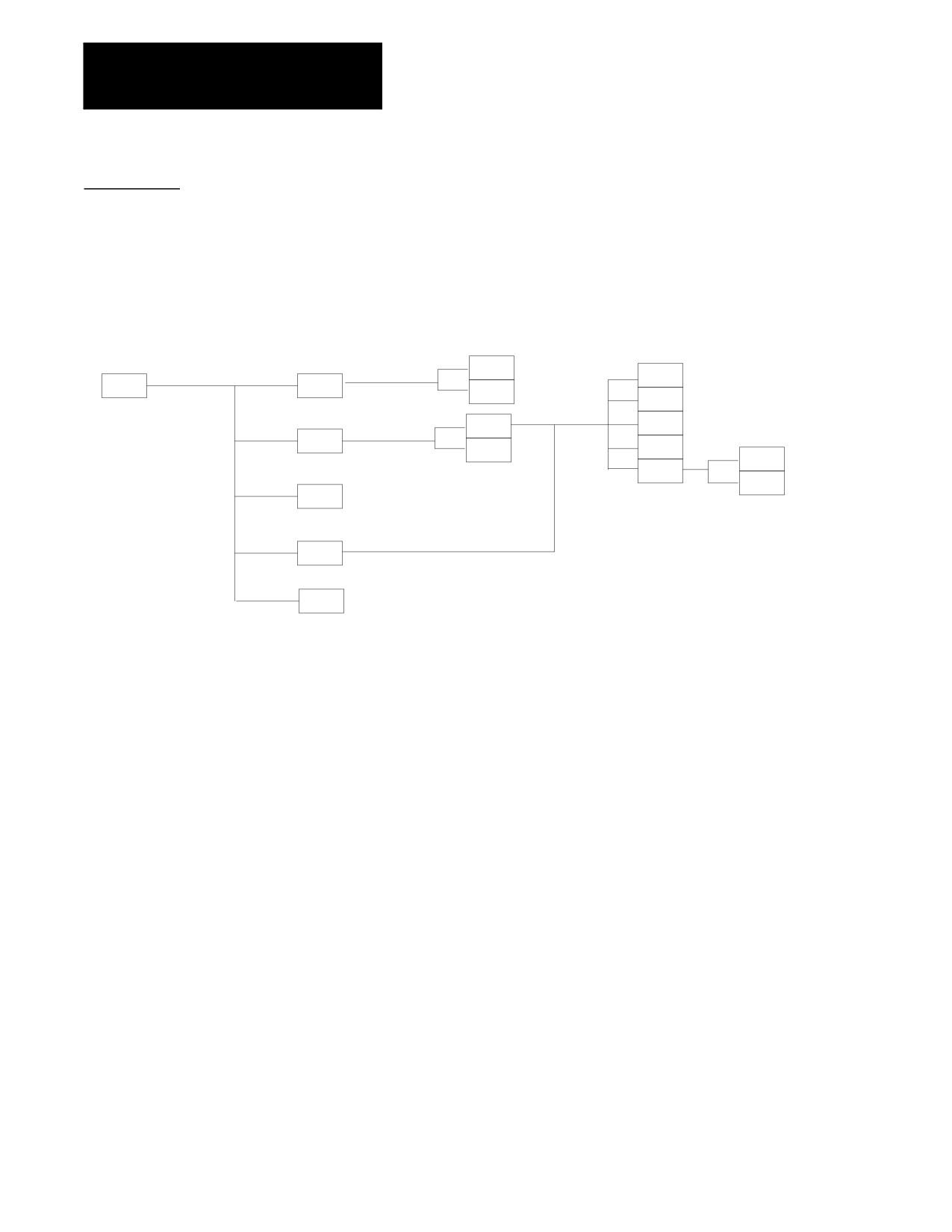
MACRO PARAM
level 1
level 2
level 3
SEARCH
NUMBER
MACRO
LOCAL
PARAM
PARAM
REFRSH
SCREEN
SEARCH
NUMBER
REPLCE
COM-1
VALUE
PARAM
ZERO
VALUE
0 ALL
VALUES
REFRSH
SCREEN
SEARCH
NUMBER
REPLCE
VALUE
ZERO
VALUE
REPLCE
NAME
CLEAR
COM-2A
NAME
PARAM
CLEAR
ALL NM
COM-2B
PARAM
0 ALL
VALUES
SHARED
PARAM
REFRSH
SCREEN
A-9
Appendix A
Softkey Tree
PRGRAM CHECK
level 1
level 2
level 3
level 4
level 5
ACTIVE
CLEAR
PRGRAM
PRGRAM
SELECT
GRAPH
DE-ACT
CHECK
PRGRAM
PRGRAM
MACHIN
INFO
GRAPH
ZOOM
WINDOW
QUICK
SYNTAX
ZOOM
CHECK
ONLY
BACK
DEFALT
GRAPH
PARAM
SETUP
SAVE
PARAM
STOP
CHECK
T PATH
GRAPH
T PATH
DISABL
A-10
Appendix A
Softkey Tree
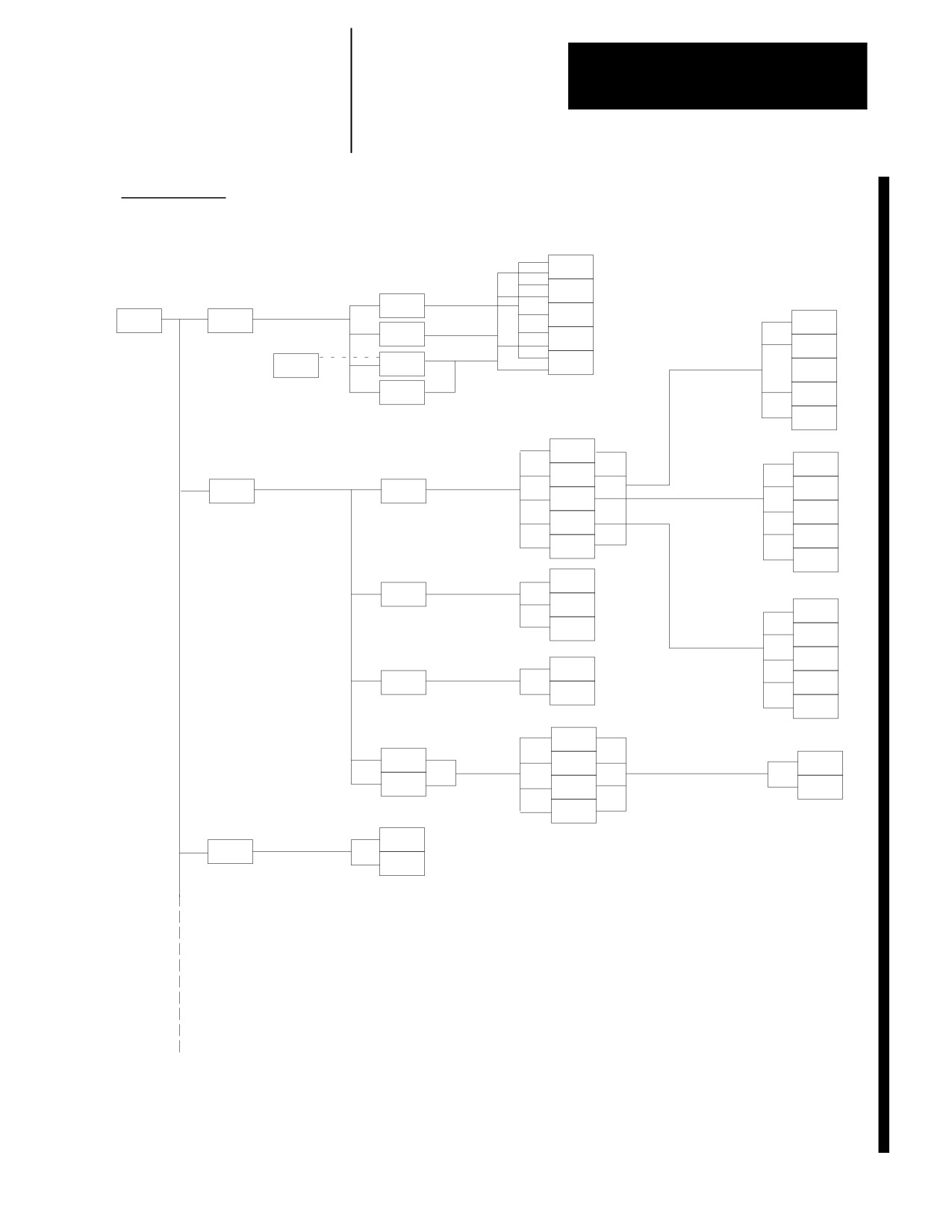
SYSTEM SUPPORT
level 1
level 2
level 3
level 4
level 5
REPLCE
VALUE
ADD TO
VALUE
ZONE
LIMITS
MORE
SYSTEM
PRGRAM
LIMITS
REPLCE
SUPORT
PARAM
VALUE
F1-F9
UPDATE
& EXIT
ADD TO
VALUE
DRLCYC
MILCYC
QUIT
(lathe only)
PARAM
PARAM
PROBE
UPDATE
PARAM
(mill only)
& EXIT
QUIT
REVERS
ERROR
REPLCE
HOME
VALUE
CALIB
AXIS
INSERT
AMP
AXIS
POINT
PARAM
CALIB
DELETE
SERVO
POINT
PARAM
UPDATE
SPNDL
& EXIT
PARAM
NEXT
AXIS
REPLCE
VALUE
PATCH
AMP
SEARCH
NUMBER
INCRE
VALUE
UPDATE
& EXIT
DECRE
VALUE
NEXT
TO
AXIS
BACKUP
UPDATE
UPDATE
BACKUP
FROM
& EXIT
BACKUP
QUIT
TO
PORT A
UPLD/
FROM
DWNLD
PORT A
YES
BACKUP
TO
AMP
NO
PORT B
FROM
PORT B
SAVE
CHANGE
DEVICE
SETUP
COPY
DEFLTS
Continued on next page
A-11
Appendix A
Softkey Tree
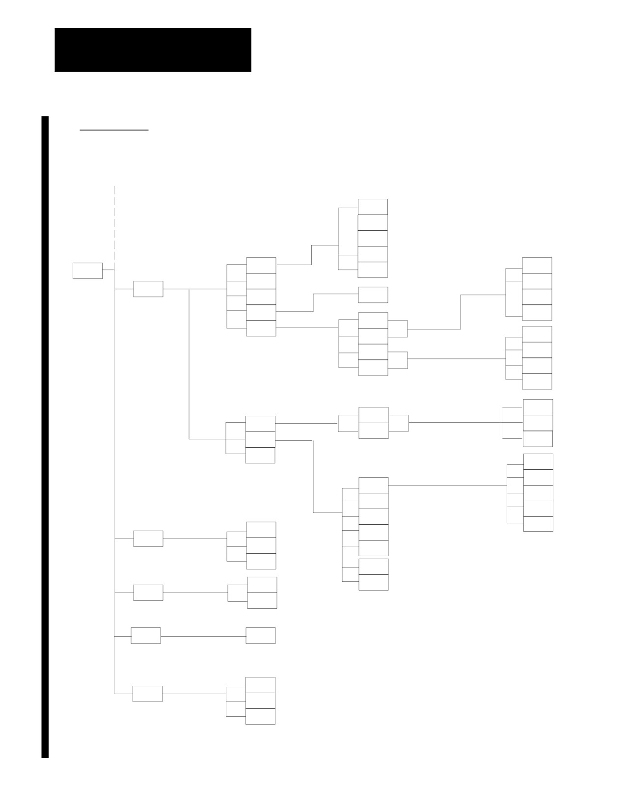
SYSTEM SUPPORT
level 1
level 2
level 3
level 4
level 5
Continued from previous page
DISPLY
RECOVR
ENABLE
RING
SYSTEM
RECOVR
START
I/O
SUPORT
DISABL
REMOTE
STOP
MONI--
I/O
TOR
FAST
@
@ = AXIS NAME
I/O
AXIS
AXIS
SINGLE
MONITOR
RECV
XMIT
SERIAL
PORT A
I/O
RECV
START
PORT B
XMIT
STOP
PORT A
XMIT
REPEAT
XMIT
PORT B
SINGLE
XMIT
FREEZE
PORT
A
UN
DATA
SCOPE
PORT
FREEZE
B
SEARCH
CLEAR
MONITR
1394
DRIVES
SELECT
RUNG
SELECT
SEARCH
OPERTR
TYPE
SELECT
FORWD
SYMBOL
SEARCH
SELECT
REVRSE
ELEMNT
SEARCH
SELECT
SET
MODULE
ADJUST
TIME
TIME
VIEW
PARTS
SET
SYMBOL
DATE
COMENT
ED PRT
INFO
DISPLY
TIME
ENTER
DISPLY
PRESET
MESAGE
PTOM
SI/OEM
STORE
BACKUP
SYSTEM
RESET
TIMING
MAXMUM
SAVER
SCREEN
ON/OFF
SAVER
INCR
TIMER
DECR
TIMER
A-12
Appendix A
Softkey Tree
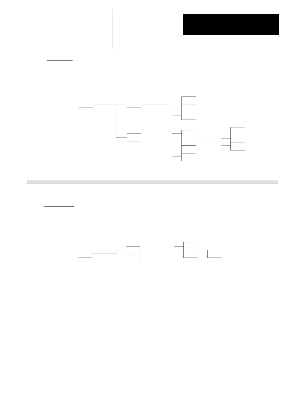
FRONT PANEL
level 1
level 2
level 3
level 4
SET
FRONT
JOG
ZERO
PANEL
AXIS
JOG
AXES+
JOG
AXES--
BLOCK
PRGRAM
RETRCE
EXEC
JOG
JOG
AXES+
RETRCT
JOG
CYCLE
AXES--
START
CYCLE
STOP
ERROR MESAGE
level 1
level 2
level 3
ACTIVE
ERRORS
ERROR
ERROR
LOG
FULL
TIME
MESAGE
CLEAR
MESAGE
STAMPS
ACTIVE
This softkey toggles between [TIME STAMPS] and [FULL MESAGE]
A-13
Appendix A
Softkey Tree
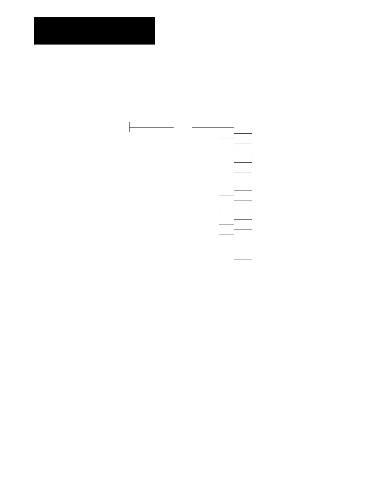
PASSWORD
level 1
level 2
level 3
PASS-
ACCESS
UPDATE
WORD
CONTRL
& EXIT
01
(NAME)
02
(NAME)
03
(NAME)
04
(NAME)
UPDATE
& EXIT
05
(NAME)
06
(NAME)
(NAME) = PASSWORD NAME
07
(NAME)
08
(NAME)
STORE
BACKUP
A-14
Appendix A
Softkey Tree
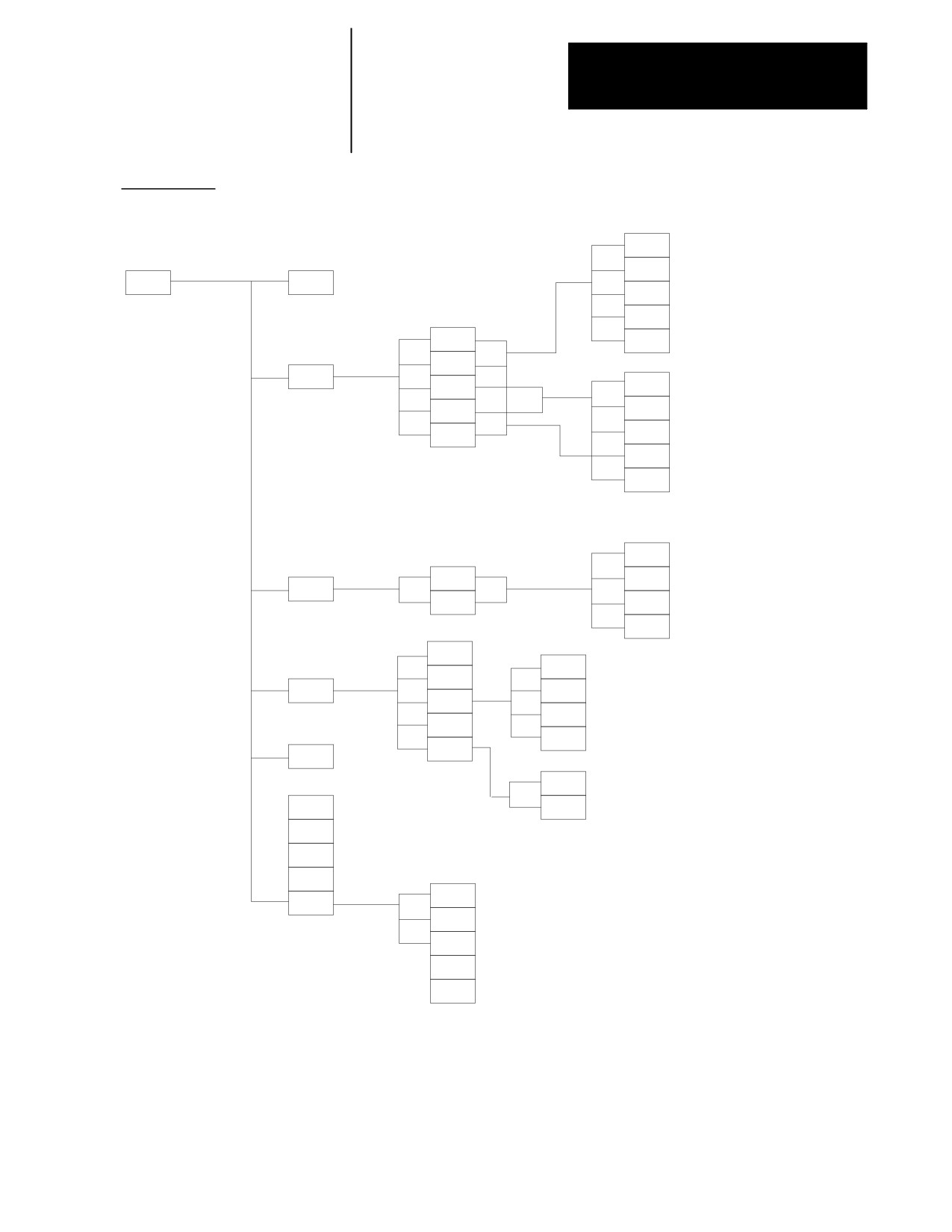
ACTIVE PRGRAM
level 2
level 3
level 4
level 5
level 6
FORWRD
REVRSE
ACTIVE
DE-ACT
PRGRAM
PRGRAM
TOP OF
PRGRAM
CANCEL
N
SEARCH
EXIT
O
SEARCH
SEARCH
EOB
FORWRD
SEARCH
SLEW
REVRSE
STRING
TOP OF
SEARCH
PRGRAM
CANCEL
EXIT
CONT
SEQ #
TOP OF
MID ST
SEARCH
PRGRAM
PRGRAM
STRING
SEARCH
QUIT
EXIT
CLEAR
GRAPHS
INCR
MACHNE
WINDOW
INFO
T PATH
DECR
GRAPH
ZOOM
WINDOW
WINDOW
ZOOM
ZOOM
ABORT
BACK
ZOOM
GRAPH
T PATH
SETUP
DISABL
DEFALT
PARAM
SEQ
SAVE
STOP
PARAM
SET
TIME
TIME
PARTS
SET
DATE
ED PRT
INFO
A-15
Appendix A
Softkey Tree
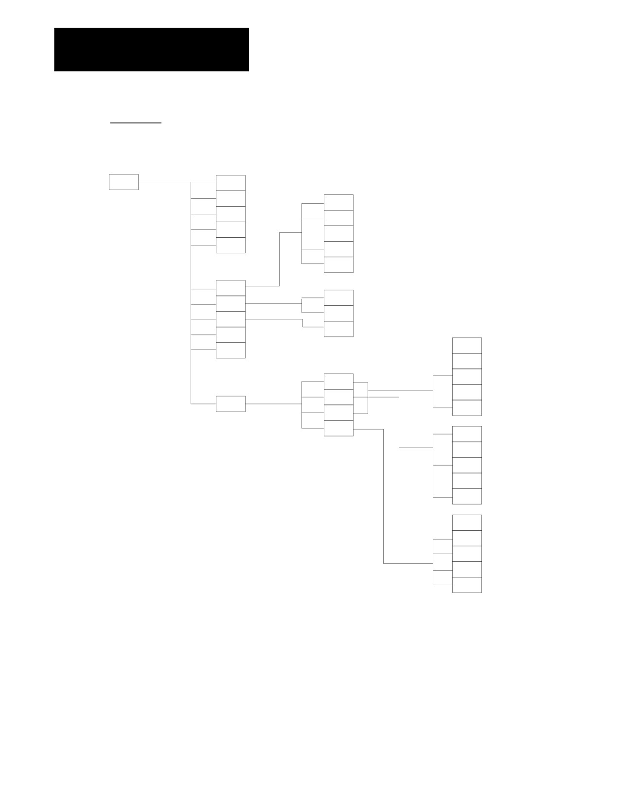
EDIT PRGRAM
level 2
level 3
level 4
level 5
EDIT
MODIFY
PRGRAM
INSERT
BLOCK
DELETE
FORWRD
BLOCK
REVRSE
TRUNC
DELETE
CH/WRD
EXIT
EDITOR
TOP OF
PRGRAM
BOT OF
PRGRAM
STRING
SEARCH
ALL
RENUM
PRGRAM
MERGE
ONLY N
PRGRAM
EXEC
QUICK
see page A-17
VIEW
CHAR/
WORD
STORE
END PT
LINEAR
CIRCLE
DIGITZ
3 PNT
E
EDIT &
CIRCLE
STORE
TANGNT
MODE
SELECT
RECORD
MID PT
STORE
END PT
EDIT &
STORE
INCH/
METRIC
ABS/
INCR
PLANE
SELECT
DIA/
(lathe only)
RADIUS
A-16
Appendix A
Softkey Tree
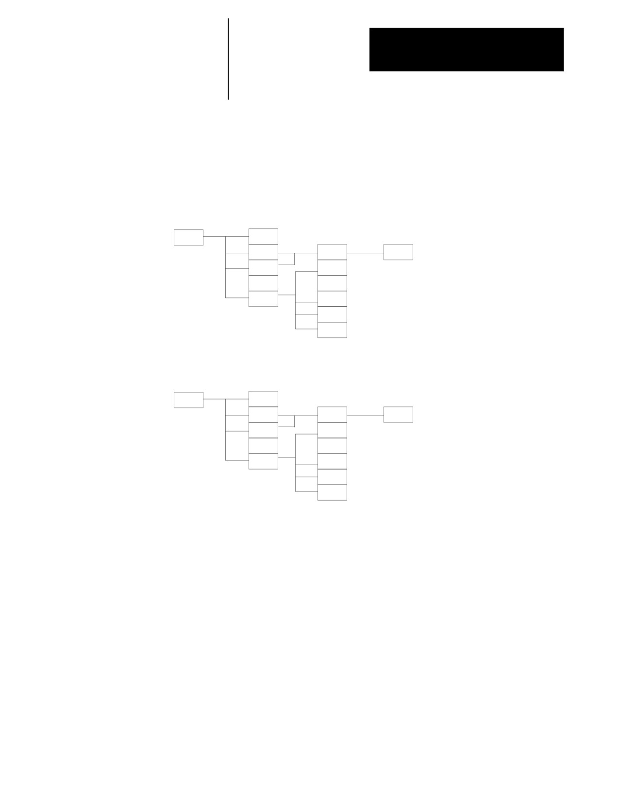
QUICK VIEW
level 3
level 4
level 5
level 6
QUICK
QPATH+
see page A-18
MILL
VIEW
PROMPT
G CODE
SELECT
STORE
PROMT
MILL
PROMPT
SET
PLANE
G17
SELECT
G18
G19
QUICK
QPATH+
LATHE
VIEW
PROMPT
G CODE
SELECT
STORE
PROMT
DRILL
PROMPT
SET
LATHE
PROMPT
PLANE
G17
SELECT
G18
G19
A-17
Appendix A
Softkey Tree
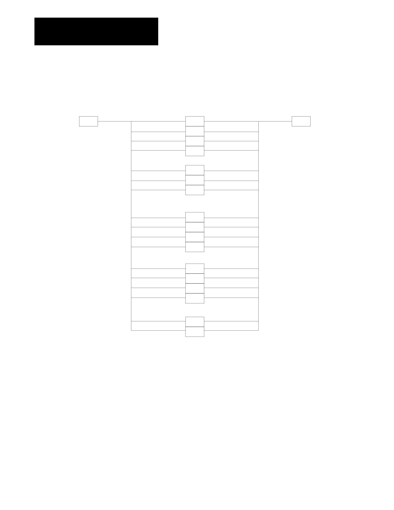
QPATH+ PROMPT
level 4
level 5
level 6
QPATH+
CIR
STORE
PROMPT
ANG PT
CIR
CIR
ANG
CIR PT
ANG
PT
2ANG
PT
2ANG
PT R
2PT R
2ANG
PT C
2PT C
2ANG
2PT 2R
3PT
2R
2ANG
2PT 2C
3PT
2C
2ANG
2PT RC
3PT RC
2ANG
2PT CR
3PT CR
END OF APPENDIX
A-18

Appendix
B
Error and System Messages
Overview
This appendix serves as a guide to error and system messages that can
occur during programming and operation of the 9/Series control. We listed
the messages in alphabetical order along with a brief description.
Important: To display both active and inactive messages, press the
{ERROR MESAGE} softkey found on softkey level 1. For details, see
chapter 2.
Important: This appendix covers only error and system messages.
PAL-generated operator messages generally appear on lines 21 and 22 of
the CRT and should be described in documentation prepared by the
machine tool builder.
Message
Description
Symbols
(+) 15V SUPPLY FAILURE
+ 15 Vdc is not available at the main processor board. Check the wires from the main power
supply and connector CN07 on the main processor board.
(--) 15V SUPPLY FAILURE
-- 15 Vdc is not available at the main processor board. Check the wires from the main power
supply and connector CN07 on the main processor board.
(+) OVERTRAVEL PROGRAM ERROR
If axis motion continues along the programmed path, the indicated axis will reach or exceed the
positive software overtravel limit (runtime error).
(--) OVERTRAVEL PROGRAM ERROR
If axis motion continues along the programmed path, the indicated axis will reach or exceed the
negative software overtravel limit (runtime error).
(+) OVERTRVL PRGRAM ERROR:
The end-point of the commanded move will cause the indicated axis to reach or exceed the
positive software overtravel limit (pre-execution error).
(--) OVERTRVL PRGRAM ERROR:
The end-point of the commanded move will cause the indicated axis to reach or exceed the
negative software overtravel limit (pre-execution error).
+/-- SIGN ERROR
A + or -- sign was found outofplace when a numeric value was being decoded. Check the
active program block for programming format errors.
1
1394 AXIS MODULE MISMATCH
At power turn on the system identified an axis module in the 1394 rack that is misconfigured in
AMP. If an extra axis module is present in the 1394 rack it should either be fully configured or
not configured at all in AMP even if that axis module is not used or detached.
1394 RING COMMUNICATIONS ERROR
At power up the internal communications ring which runs through the front of the 1394 system
and drive modules was either not connected, a device on the ring experienced a hardware
failure, or a device on the ring was discovered to be misconfigured once a command was sent to
the device. Make sure all axis modules and the end terminator are properly connected to
complete the communication ring.
1746 RACK CARDS MISMATCH
The I/O configuration for the 1746 I/O rack that was downloaded from ODS, or resides in the
PAL PROMs, contradicts what is actually in the rack (devices must match slot-for-slot).
1771 RACK CARDS MISMATCH
The I/O configuration for the 1771 I/O rack that was downloaded from ODS, or resides in the
PAL PROMs, contradicts what is actually in the rack (devices must match slot-for-slot).
B-1
Appendix B
Error and System Messages
Message
Description
2
2MB RAM IS BAD/MISSING
The control has discovered the RAM SIMMs for the two megabyte extended storage option are
either damaged or missing. The RAM SIMMs must be installed or replaced. Contact your Allen
Bradley sales representative for assistance.
9
9/SERIES LATHE - CANNOT USE MILL AMP
The control was powered up with a lathe software option chip installed, when the AMP file that
was downloaded was configured for a mill.
9/SERIES MILL - CANNOT USE LATHE AMP
The control was powered up with a mill software option chip installed, when the AMP file that
was downloaded was configured for a lathe.
7300
7300 NAMES TABLE IS CORRUPTED
7300 program name doesn’t match corresponding name in cross-reference table.
7300 PATTERN NAME TOO LONG
More than 5 digits have been used in the pattern name.
A
A RETRACE BUFFER WAS DELETED
The control required one (or more) of the block retrace buffers to perform a necessary block
look-ahead operation (refer to block look-ahead in the user’s manual). When this occurs, less
block retrace operations can be performed than AMP is configured to allow. If this error occurs,
to improve control efficiency, it is recommended that the number of allowable block retrace
blocks set in AMP be lowered or add additional RAM to you system.
ABS POSITION NOT INITIALIZED
This message indicates that axes with absolute encoders have not been homed. These axes
require an initial homing operation to establish the absolute position.
ABSOLUTE FEEDBACK FAILURE
The control has detected a loss of feedback from the absolute encoder. The most likely cause
of this error would be a broken or disconnected wire. Axis homing may be required after the
error condition is corrected.
ACC/DEC CONFIGURATION ERROR
An axis configuration error was detercted by the control when manual acc/dec was requested in
a program block.
ACCUM. AND EXPECTED LIFE ARE 0
No tool life data was entered for the current tool selected by the tool life management feature.
Tool life management will be disabled for this tool.
ACTIVE GROUP CANNOT BE DELETED
An attempt was made to delete a tool group in the tool life management feature that contains an
active tool currently in the tool holder.
ACTIVE OFFSET CANNOT CHANGE
An attempt was made to alter a tool offset value of a tool offset that is currently the active tool
offset on the control. The active tool offset is indicated with an * on the tool offset table.
ACTIVE TOOL CANNOT BE CHANGED
An attempt was made to edit tool data for the currently active tool. De-activate the tool before
editing.
ACTIVE TOOL CANNOT BE DELETED
An attempt was made to delete tool data for the currently active tool. De-activate the tool before
editing.
ADAPTIVE FEED MIN LIMIT
This message indicates your are exceeding the programmed desired torque. The actual torque
is greater than the desired programmed torque and the adaptive feed axis has reached the
programmed minimum feed limit. Either raise the programmed desired torque or lower the
minimum feed limit.
ADAPTIVE FEED PROGRAMMING ERROR
E and Q must both be programmed in every G25 block.
ALL DUAL AXES ARE PARKED
An attempt was made, while using dual axes, to move the dual group when all the axes of that
group were parked.
AMP FILE SIZE ERROR
The size of the AMP file being downloaded is incorrect. The file cannot be downloaded.
AMP IN BACKUP DOES NOT MATCH AMP IN RAM
This message always appears after a successful AMP download if the downloaded file is
different from the one currently stored in backup memory. Its purpose is to remind the user to
copy the downloaded AMP into backup memory after testing it.
B-2
Appendix B
Error and System Messages
Message
Description
AMP WAS MODIFIED BY PATCH AMP UTILITY
This message always appears after changes have been made to AMP using the patch AMP
utility. Its purpose is to remind the user that the current AMP has not been verified by a
cross-reference check normally performed by ODS. It is meant as a safety warning.
AMPED HOLDING OR DETECT TRQ OUT OF RANGE
This message is displayed when you have entered a value in AMP for either the holding torque
or the detection torque, for the feed to hard stop feature, that is higher than the value entered for
the servos available peak torque. You must change your AMP values.
ANALOG SERVO VOLTAGE FAILURE
A + 15V to the servo cards has failed.
ANGLE WORD NOT ALLOWED
An angle word was programmed in a QPP block where it is not allowed, for example,
programming an angle word in a circular QPP block.
ANGLED WHEEL AXES, JOG ONE AT A TIME
While in the angled wheel grinding mode you can not jog more than one axis in the angled
wheel plane at any one time.
ANGLED WHEEL CONFIG ERROR
The angled-wheel grinder AMP downloaded to the control is not configured correctly. Make sure
all necessary angled-wheel parameters are configured correctly and re-download AMP to the
control.
ANGLED WHEEL NOT CONFIGURED
You have attempted to program an angled wheel grinder mode function and the angled wheel
feature has not been correctly configured for your system. The angled wheel feature must be
configured in AMP and is a purchased option for your 9/Series control.
ARCTAN SYNTAX ERROR
An attempt was made to calculate or execute a paramacro block that calculates the arc tangent
of an invalid or improperly entered number.
ARITHMETIC OVERFLOW ERROR
An internal math error has occurred; contact Allen-Bradley customer support service.
ARITHMETIC UNDERFLOW ERROR
An internal math error has occurred; contact Allen-Bradley customer support service.
AUX FB NOT ALLOWED WITH DEPTH PROBE
Your AMP file has a depth probe configured for an axis that also is configured to use an optional
feedback device. A depth probe can not be configured to use any feedback device other then
its depth probe for that depth probe axis. If a second feedback device is used it is configured in
AMP as a separate logical axis.
AUXILIARY FEEDBACK DISCONNECTED
The digital servo module provides the capability to use two different feedback encoders with one
servo (in the case where two encoders are used, the auxiliary encoder is used for the position
feedback). If the servo processor detects that the auxiliary encoder has been disconnected, this
message is displayed.
AUXILIARY FEEDBACK QUADRATURE FAULT
The digital servo module provides the capability to use two different feedback encoders with one
servo (in the case where two encoders are used, the auxiliary encoder is used for the position
feedback). If the servo processor detects a quadrature fault on the auxiliary encoder, this
message is displayed.
AUXILIARY SPINDLE 2 NOT CONFIGURED
For aux spindle 2 to be programmable, it must be configured in AMP; a decode error.
AUXILIARY SPINDLE 3 NOT AVAILABLE
AMP configuration error; aux spindle 3 can be configured only on a 9/290.
AUXILIARY SPINDLE 3 NOT CONFIGURED
For aux spindle 3 to be programmable, it must be configured in AMP; a decode error.
AXES COLLISION
Two processes have collided. Interference checking has stopped all motion.
AXES CONFIGURED ON INACTIVE PROCESS
An AMP was loaded that contains an axis that was configured for an inactive process. Set the
process axis in AMP to a process that has been configured.
AXES DATA MISSING
Expected axis data is missing in a program block.
AXIS AMPED AS NON-SCALING AXIS
The user attempted to scale an axis that was AMPed as non-scaleable.
AXIS ASSIGNED TO PAL AXIS MOVER
The user attempted to move the axis configured as the PAL axis mover axis by some means
other than PAL.
AXIS DISPLAY DISABLED BY PAL
The position display for a selected axis has been turned off using the $NODP flag.
AXIS IN PLANE DOES NOT EXIST
At least one of the axes assigned to a plane that was defined in AMP does not exist. An
example of when this error would occur is if an axis was renamed in AMP, but that new name
was not entered into the AMP plane definition. Another example would be if an unfitted axis
was assigned to that plane.
B-3
Appendix B
Error and System Messages
Message
Description
AXIS INVALID FOR G24/G25
The programmed axis was not AMPed for software velocity loop operation, and can not be used
in a G24 or G25 block. To use these features the axis programmed must be configured for
tachless operation (or be a digital servo).
AXIS IS HARD STOPPED, CANT ADJUST SERVO
The torque limit of the servo can not be adjusted because, either the axis is in a hard--stopped
state, or some other axis on the same servo card is in a hard--stopped state.
AXIS MODULE POWER FAULT
The current through the power output transistors is monitored. If the current exceeds a fixed
level (greater than 300% of controller rating) this fault will appear. Typical causes are a shorted
lead, motor malfunction, or malfunctioning power IGBTs.
AXIS MODULE OVER CURRENT
One of the axis modules of your 1394 drive has been requested to provide too much current.
This is typically caused by Accel/Decel command from the CNC is requiring peak current for an
excessive amount of time, the machine friction or inertial/viscous load is excessive, the motor
has been improperly sized, a short circuit exists across the drive output terminals, logic supply
circuits have malfunctioned, or AC input is incorrectly wired.
AXIS MODULE BUSS VOLTAGE LOSS
The DC bus supply was lost to the axis module. Check slider connections/termination strip or
there could be a blown link fuse.
AXIS MODULE OVER TEMP
The 1394 contains a thermal sensor which senses the internal ambient temperature. Causes
could be: that the cabinet ambient temperature is above rating. The machine duty cycle
requires an RMS current exceeding the continuous rating of the controller. The airflow access to
the 1394 is limited or blocked. This does not necessarily indicate a motor over temperature.
Motor over temperture sensors should be wired directly into the E-Stop string.
AXIS MOVER CONFLICT WITH G16.3/G16.4
You have requested a PAL axis mover function on an angled wheel grinder. You can not use the
PAL axis mover in one of the angled wheel modes unless the PAL axis mover has control of
both the axial and the wheel axes.
AXIS NAME DUPLICATE
Two or more axes have been assigned the same name in AMP.
AXIS NOT IN PROCESS
You attempted to read/write a paramacro parameter for an axis that is not currently in the
process requesting the data. To access paramacro parameter data for an axis, that axis must
be in the process making the request.
AXIS POSITION INCORRECT
Using the mid-start program function, you have searched to a block that does not create the
programmed contour if started from your current axis position. Be aware the mid-start operation
may have searched thru a offset operation that is not readily apparent to determine your axis
position. The mid-start operation is aborted. You must re-perform the mid-start operation and
either position the axes to the correct axis position, or use the {MOVE & EXIT} softkey to find the
correct axis position.
AXIS SELECT NOT ALLOWED
The {AXIS SELECT} softkey was pressed when no axis select option is available. Axis select is
only available on large screens and normal character size screen for systems that contain more
then 9 axes total or dual process systems with more than 8 axes in a process. It is not available
when the small screen (showing all system AMPed axes) is being viewed.
AXIS TYPE-POSITION LOOP ERROR
In patch AMP, an axis was assigned a position loop type that is illegal for the axis type assigned
to that axis.
B
BACKUP VERSION OF AMP WAS COPIED TO RAM
The AMP in RAM was erased (battery backup failed) or corrupted, so the control automatically
copied the version of AMP in backup memory into RAM memory. (The control stores AMP in
backup, but works from the copy of AMP in RAM memory.)
BAD DAC MONITOR PATCH AMP ENTRY
An invalid value was entered into patch AMP parameter #86 or #87. Either parameter allows
the axes to be monitored through the servo module (DAC) analog output. See documentation
provided by Allen-Bradley on patch AMP, or contact Allen-Bradley customer support service.
BAD FIRST POCKET BLOCK
When performing an irregular pocket cycle, the first pocket block should be away from the
pocket start/end corner, not toward it. The move to the start/end corner is generated based on
the coordinates programmed in the pocket definition block itself.
BAD PAL PROM
One of the PAL PROM chips (plugged into the main processor board) has failed or is not
plugged in properly.
B-4
Appendix B
Error and System Messages
Message
Description
BAD RAM DISC SECTOR CHECKSUM ERROR
A RAM disk sector error was detected during the RAM checksum test at power-up. Attempt to
power-up again. If the error remains, contact Allen-Bradley customer support services.
BAD RECORD IN PROGRAM
This indicates a serious problem with the program. Attempt to open the program a second time.
If retry doesn’t work, you may have to delete the program. Typically this error is not caused by a
programmer or operator action. It is typically caused by an internal software error in the
program.
BAD STATE/TOKEN COMBINATION (PROGRAM
While attempting to decode the current block, a combination of characters caused a decode
ERROR)
error to occur. Check the characters in the current block for an illegal combination.
BATTERY FAILURE
The battery that provides backup of the RAM memory is not functioning; the voltage may be low.
The battery may be dead, removed, or poorly connected.
BLK DELETE CHG IGNORED ON PREPARED BLKS
A block-delete was activated while a program was executing. This change is ignored by the
control for blocks that have already been read into the control’s set-up buffer (see block
look-ahead in user’s manual).
BLOCK LENGTH ERROR
A block that exceeds the allowable maximum block length was programmed.
BLOCK RETRACE ABORTED
The block retrace operation being performed has been canceled. When <CYCLE START> is
pressed, the control will return the tool along a linear path back to the start-point of the block
retrace operation.
BOOT DIRECTORY IS MISSING
The update utility failed to properly create the system boot directory. Retry the update. If the
error occurs again, contact your local Allen Bradley service.
BOOTSTRAP FAILED TO START
The bootstrap code did not send the “ok”signal to the main processor within the specified time.
BOTH AXES IN QPP PLANE NOT PRGMD
The second block of a currently executing QuickPath Plus two-block set does not contain both
required axis words in the current plane. Both axis words are required to correctly identify the
end-point of the second move.
BOTH LINES ARE PARALLEL
Both blocks of a two-block QPP sequence are parallel, and no mathematical intersection can be
computed.
BOTH PORTS ARE BUSY
An attempt was made to use or monitor communication ports A or B when neither were
available.
BUSY, REQUEST IGNORED
You have requested an operation while the control is currently executing some other higher
priority function. The control must first complete the higher priority task before your new task
can be performed.
C
CALLED 7300 PATTERN NAME IS BAD
The 7300 pattern name that is called by a part program does not exist .
CANCEL/REMOVE OFFSET BEFORE AXIS CHANGE
You have attempted to change the active tool length axis while an length offset is currently
active on that axis. You must cancel tool length offsets before you are allowed to change the
active tool length axis.
CANNOT (GOTO) TO INSIDE A (DO)
A (GOTO) command cannot transfer execution to a block which is located within a (DO) loop.
CANNOT ACCESS REMOTE VARIABLE
Variable name is invalid. Check the fields for CNC name and remote name, and make sure they
are in the correct format.
CANNOT ACTIVATE - OPEN PROGRAM
An attempt was made to activate a program for execution when it was still open for an editing
operation. Before it can be activated for automatic execution, it is necessary to press the {EXIT
EDITOR} softkey from the edit menu to close a program being edited.
CANNOT ACTIVATE RAM PARTITION
The RAM disk has been corrupted. Attempt to perform a “REFORMAT”operation. If this is
unsuccessful, consult Allen-Bradley customer support services.
CANNOT ASSIGN IN CURRENT MODE
An attempt was made to modify a paramacro parameter that cannot be modified when the cutter
compensation or TTRC feature is active.
CANNOT CALCULATE - PROMPT PRESENT
An attempt to perform a calculate operation was made when some other prompt was present on
line 2 of the CRT. Before the control will allow a calculation to be made, it is necessary to
remove any prompts from line 2 .
B-5
Appendix B
Error and System Messages
Message
Description
CANNOT COPY
The requested copying task cannot be performed due to an internal problem in the file or RAM
disk. Contact Allen-Bradley customer support service.
CANNOT DELETE - OPEN PROGRAM
The selected program is either active or open for editing and cannot be deleted.
CANNOT DELETE ALL PROGRAMS
An attempt was made to delete all part programs or to reformat RAM while a program was being
edited or was currently selected as the active program for execution.
CANNOT DELETE PROGRAM
The file selected cannot be deleted. This is caused by a major error being detected in the actual
software file of the program. It may be necessary to “REFORMAT”RAM to remove the
program. If this is unsuccessful, contact Allen-Bradley customer support service.
CANNOT DIVIDE BY ZERO
An attempt was made to divide a quantity by zero, either using the CALC functions or in an
executing program with a paramacro operator.
CANNOT EDIT -- FILE UPLOADING
The file you’ve tried to open is already open and is in the middle of a part program upload or
download operation with ODS.
CANNOT EDIT - MUST BE IN CYCLE OR E-STOP
An attempt was made to edit a part program while another part program was currently being
executed.
CANNOT EDIT - OPEN PROGRAM
The program that you have selected for editing is currently open for another feature.
CANNOT EDIT - OTHER FILE IS BEING EDITED
An attempt was made to edit a part program while another part program was currently being
edited.
CANNOT EDIT ACTIVE PROGRAM
An attempt was made to edit a program that is currently selected as the active program for
execution. Before it can be edited, the program must first be disabled.
CANNOT EXIT IN CYCLE
You cannot exit in the middle of a roughing cycle because it executes at runtime, not during
setup.
CANNOT FIND CORRECT POSITION
The program-restart feature cannot locate the correct program block in the program at which
automatic execution was interrupted. To position the program at the correct block, it will be
necessary to perform one of the other search operations. The operator must know what this
correct block is as the control has failed its recover operation.
CANNOT FIND PAL PAGE
PAL requested a PAL display page to be displayed that does not exist in the display page file.
CANNOT FORMAT - OPEN PROGRAM
A program was selected for automatic execution or was still in the edit mode when a request to
format memory was made. The active program must be disabled by pressing the {CANCEL
PRGRAM} softkey, and any program being edited must be closed by pressing the {EXIT
EDITOR} softkey before formatting memory.
CANNOT FORMAT RAM PARTITION
The control is unable to format memory due to open file conditions indicating a more serious
problem. Consult Allen-Bradley customer support services.
CANNOT JOG -- ALL AXES ARE PARKED
An attempt was made to jog a dual group when all the axes were parked.
CANNOT MERGE WITH SAME PROGRAM
An attempt was made to merge the same program that is being edited with itself. If this is
desirable, first copy the original program, then merge the copy into the original.
CANNOT OPEN DIRECTORY
This indicates a serious RAM disk problem. If retry doesn’t work, you may have to reformat.
CANNOT OPEN PROGRAM FOR READ
This indicates a serious problem with the program. If retry doesn’t work, you may have to delete
the program.
CANNOT OPEN PROGRAM FOR WRITE
An error occurred while attempting to open a file on the RAM disk. Either the RAM disk is full, or
there is an internal problem with the file. The file may need to be deleted.
CANNOT OPEN SUBPROGRAM
An attempt to call a sub-program has failed. This is usually caused by the sub-program name
(programmed in the calling block with a P-word) not existing in the current program directory.
CANNOT READ A WRITE-ONLY PARAMETER
An attempt was made to use the value of a paramacro system parameter that is a write-only
parameter. This parameter may have only its value written to. It cannot be read.
CANNOT READ DIRECTORY
This indicates a serious RAM disk problem. If retry doesn’t work, you may have to reformat.
CANNOT READ PROGRAM
This indicates a serious problem with the program. If retry doesn’t work, you may have to delete
the program.
B-6

Appendix B
Error and System Messages
Message
Description
CANNOT RENAME
When performing a rename of a program name, the new program name has not been correctly
entered. The format is OLD PROGRAM NAME,NEW PROGRAM NAME.
CANNOT REPLACE START POINT
An illegal attempt was made to change the axis calibration start-point using the online AMP
feature.
CANNOT RESTART G24 HARD STOP
An attempt was made to restart a part program on a block which would have an axis at the hard
stop. You cannot restart or mid start a part program after if (at that blocks execution) any axis
would be holding against a hard stop. You must either re-start/mid--start to a block before the
G24 hard stop block or to a block after the hard stop is released.
CANNOT SEND AVAILABLE COMMAND
This is displayed when a non-programmed communications command is executed from
“send’softkey.
CANNOT SET DATA WHEN TOOL IS ACTIVE
An attempt was made to manually (using the softkeys) change tool management data for the
currently active tool. Tool management data can be changed only for a tool that is not currently
selected as the active tool.
CANNOT TAP IN CSS
You must disable the CSS feature before you begin a tapping operation. Disable CSS using a
G97 command.
CANNOT TAP IN VIRTUAL-C MODE
You attempted to use the solid tapping feature while cylindrical or end-face milling was active.
CANNOT UPLOAD - PAL NOT IN PROM
PAL can be uploaded only from the PAL PROMs. PAL in RAM memory cannot be uploaded.
CANNOT UPLOAD - PAL SOURCE NOT LOADED
When the source is loaded, PAL can be uploaded in the 9/240 only . The 9/260 and 9/290
always have PAL in flash.
CANNOT USE COPY WITH ACTIVE TOOL OFFSET
An attempt was made to copy offset data from one axis to another using the {COPY OFFSET}
softkey. You cannot use this softkey if the tool offsets are active.
CANNOT USE EXIT - BLOCK NOT FOUND
An attempt was made to {EXIT} while searching for a block for a mid-program start. You cannot
use {EXIT} until the block has been found. To abort the search, use {QUIT}.
CANNOT WRITE A READ-ONLY PARAMETER
An attempt was made to assign a value to a PAL or system paramacro parameter that is a
read-only parameter. The value of these parameters can be used only by the programmer; they
cannot be altered in the program.
CANNOT WRITE TO PROGRAM
This indicates a serious problem with the program. Attempt to write to program a second time.
If retry doesn’t work, you may have to delete the program. Typically this error is not caused by a
programmer or operator action, but rather by an internal program software error.
CAUTION! YOU ARE IN 7300 TAPE MODE
The operator is cautioned that the tape being copied is presumed to be a 7300 formatted tape.
TO RETURN TO STANDARD 9/240 MODE
This message is displayed on the copy-tape set-up screen when the MCU is in 7300
RESET THE 7300--COMPATIBILITY PAL FLAG
compatibility mode.
CC/TTRC ON, CAN’T ASSIGN TIME DEP. PARAM
An attempt was made to assign a time-dependent paramacro system parameter while
dresser/wheel radius compensation was active. Time-dependant parameters are any system
parameters that record or reference a current axis position.
CHAMFER LENGTH/RADIUS TOO LARGE
A chamfer or radius value programmed with a ,C or ,R would generate a chamfer or radius that
is larger than one or both of the two adjacent tool paths.
CHAMFER/RADIUS NOT ALLOWED
An attempt was made to perform a chamfer or radius cut (programmed with a ,R or ,C) in a
block that does not allow these functions to be performed. For example, you cannot do a
chamfer or radius cut in a non-motion block, in the last block on an MDI line, or in the last block
of a part program.
CHANGE NOT MADE IN BUFFERED BLOCKS
Changes to the offset table did not affect those program blocks that were already in the control
s
current activation queue. Program blocks that call for offsets and which follow those already in
the activation queue will call the updated offset tables.
CHANNEL NAME TOO LONG
There is an error in G05 DH+ communications block.
CHAR MUST BE _, ., LETTER, DIGIT
You have used incorrect search string syntax in the PAL search monitor utility.
CHAR MUST BE LETTER,DIGIT, UNDERSCORE
You have used incorrect search string syntax in the PAL search monitor utility.
CHARACTERS MUST BE DIGIT
You have used incorrect search string syntax in the PAL search monitor utility.
B-7
Appendix B
Error and System Messages
Message
Description
CHARACTERS MUST FOLLOW WILDCARD
You have used incorrect search string syntax in the PAL search monitor utility.
CHECKSUM ERROR IN FILE
The file (AMP, PAL) being downloaded from a storage device has a checksum error. The file
cannot be used.
CIRCLE MID-POINT NOT ENTERED
The center-point of an arc is not entered in a circular programming block. Circular blocks
require programming either an R or an I, J, K in the block.
CIRCULAR BLOCK NOT ALLOWED
When activating cutter compensation, you cannot program a circular block as the first block or
as the last block prior to deactivating cutter compensation.
CIRCULAR NOT ALLOWED AFTER SKIP
A circular move cannot immediately follow a G31 or G37 series skip block. Only linear moves
are permitted as the next move following a G31 or G37 type code.
CIRCULAR PROGRAMMING ERROR
A circular motion was programmed incorrectly. Typically this occurs from incorrectly
programming an R or I, J or K value.
CODING ERROR
A system software error has occurred. Consult Allen-Bradley customer support services.
COM COMMAND TABLE IS CORRUPTED
Restore the flash version of the output command table.
COM CONFIGURATION TABLE IS CORRUPTED
Restore the flash version of the communication configuration table.
COMM ERROR WHILE PROCESSING HOST REQUEST
A communication error occurred between your PC and 9/Series while performing an update
utility. Retry at a lower baud rate. If that does not work check communication ports, connections
and cable wiring.
COMMUNICATION TIME-OUT
The time allowed for a peripheral device to respond has elapsed. Check cable connections and
device set-up.
COMMUNICATIONS DISPLAY PAGE ENABLED
When a remote host enables the 9/Series remote operator display screen, this message is
displayed.
COMMUNICATIONS LINK IS DOWN
A problem was detected in the communications line. Check the cables and retry the
download/upload.
COMPLETED WITH ERROR(S)
A QuickCheck syntax check operation has completed the check of the currently active program
and found one or more errors. Some editing of the program is required.
COMPLETED WITH NO ERRORS
A QuickCheck syntax check operation has completed the check of the currently active program
and found no syntax errors.
CONFIGURATION EXCEEDS AVAIL MEMORY
This error occurs when the amount of available control memory drops below what is required to
maintain a minimum 5 block setup buffer for program execution. The system is held in E-Stop
when this error occurs. You may either chose to add more memory to your system or
re-configure your system by decreasing the watch list allocation (in AMP) for OCI systems.
CONTINUE NOT ALLOWED
An attempt was made to continue a program search when no character string was entered. This
can occur when an error is generated by the program being searched and the control cannot
continue the search of the program correctly.
CONTROL RESET NOT ALLOWED
The Control Reset Request was not honored by the control (e.g., a Control Reset Request
during Cycle Suspended state).
CORRUPTED PROGRAM FOUND & DELETED
Program was found to be corrupted and not usable. This program was deleted.
CPU #2 DUALPORT RAM FAILED
The DUALPORT RAM memory shared between the 68000 main processor and the Z80 I/O ring
processor has failed. (two 98030’s instead of the 68000 and Z80 on 9/230, 9/260, and 9/290
controls)
CPU #2 EXEC IS BAD/MISSING
CPU #2 exec is not in flash; you must use update utility to load it (9/290 only). Consult
Allen-Bradley customer support services.
CPU #2 EXEC WILL NOT START
CPU #2 is halted and will not start to execute its exec (9/290 only). Consult Allen-Bradley
customer support services.
CPU #2 HARDWARE ERROR #2
The 68030 main processor has detected a bus error. Consult Allen-Bradley customer support
services (9/290 only).
CPU #2 HARDWARE ERROR #3
The 68030 main processor has detected a spurious interrupt. Consult Allen-Bradley customer
support services (9/290 only).
B-8

Appendix B
Error and System Messages
Message
Description
CPU #2 HARDWARE ERROR #4
The 68030 main processor has detected an illegal address. Consult Allen-Bradley customer
support services (9/290 only).
CPU #2 HARDWARE ERROR #6
The 68030 main processor has detected a privilege violation. Consult Allen-Bradley customer
support services (9/290 only).
CPU #2 HARDWARE ERROR #8
CPU #2 has detected an unassigned vector interrupt. Consult Allen-Bradley customer support
services (9/290 only).
CPU #2 HARDWARE ERROR #9
CPU #2 has detected an illegal instruction. Consult Allen-Bradley Customer Support Services
(9/290 only).
CPU #2 LOCAL RAM FAILED
The RAM memory supporting the 68030 I/O ring processor has failed (Z80 I/O ring processor on
9/240 only). Consult Allen-Bradley customer support services.
CPU #2 PROM HAS FAILED
The PROM memory supporting the 68030 (Z80 9/240 only) I/O ring processor has failed its
checksum test. Consult Allen-Bradley customer support services.
CPU #2 RAM HAS FAILED
The RAM memory supporting the 68030 (Z80 9/240 only) I/O ring processor has failed. Consult
Allen-Bradley customer support services.
CPU #2 WATCHDOG ERROR
The 68030 (Z80 9/240 only) I/O ring processor has failed. Consult Allen-Bradley customer
support services.
CREATING BACKUP FILE - PLEASE WAIT
A backup file for the current utility is being created. The message will clear when the backup is
complete.
CREATING TOOL OFFSET FILE - PLEASE WAIT
The tool offset table (or tables) is currently being backed-up. The control is generating an
executable G10 program and entering it into the control’s program directory.
CREATING TOOL MGMT. FILE - PLEASE WAIT
The tool management tables are currently being backed-up. The control is generating an
executable G10 program and entering it into the control’s program directory.
CSS RPM LIMIT AUXILIARY SPINDLE 2
The aux spindle 2 RPM requested by CSS is greater than the maximum CSS RPM limit. This
limit is set by the system installer in AMP or can be reduced by programming a G92 block.
CSS RPM LIMIT AUXILIARY SPINDLE 3
The aux spindle 3 RPM requested by CSS is greater than the maximum CSS RPM limit. This
limit is set by the system installer in AMP or can be reduced by programming a G92 block.
CSS RPM LIMIT FIRST SPINDLE
The spindle 1 RPM requested by CSS is greater than the maximum CSS RPM limit. This limit is
set by the system installer in AMP or can be reduced by programming a G92 block.
CSS RPM LIMIT PRIMARY SPINDLE
The primary spindle RPM requested by CSS is greater than the maximum CSS RPM limit. This
limit is set by the system installer in AMP or can be reduced by programming a G92 block.
CSS RPM LIMIT SECOND SPINDLE
The spindle 2 RPM requested by CSS is greater than the maximum CSS RPM limit. This limit is
set by the system installer in AMP or can be reduced by programming a G92 block.
CSS RPM LIMIT THIRD SPINDLE
The spindle 3 RPM requested by CSS is greater than the maximum CSS RPM limit. This limit is
set by the system installer in AMP or can be reduced by programming a G92 block.
CUR LOOP G/A CLOCK LOST
This error was generated by a servo amplifier error. It can usually be corrected by turning off
power to the amplifier, and then back on.
CURRENT FEEDBACK ERROR
The servo module has detected faulty or missing current feedback from the digital servo motor.
The most likely cause of this error is be a broken or disconnected wire.
CURSORING NOT ALLOWED
While assigning a {CUSTOM TOOL} in {RANDOM TOOL}, you cannot cursor to select another
tool position.
CUTTER COMP./TTRC INTERFERENCE
The cutter radius is too large, reverse motion is required, or some other cutter compensation
interference exists. Either an alternate tool or an alternate tool path must be programmed.
Another option would be to disable cutter compensation error detection.
CYCLE ALREADY ACTIVE
An attempt was made to start a cycle while another cycle was currently executing.
CYLINDER RADIUS IS ZERO
The cylinder radius was not programmed in a virtual C cylindrical interpolation (G16.1) cycle.
CYLINDRICAL AXIS NOT PRESENT
Cylindrical interpolation was programmed without at least one cylindrical interpolation axes
present (rotary, park, or feed axes).
B-9
Appendix B
Error and System Messages
Message
Description
CYLIND/VIRTUAL CONFIGURATION ERROR
An axis configuration error was detected by the control when cylindrical interpolation or end face
milling was requested in a program block. Some examples would include:
A cylindrical/virtual axis is named same as a real axis or is missing (for example on a
lathe A, the cylindrical axis may have been named the same as a incremental axis name).
A cylindrical/virtual axis is named the same as another programing command (for example
a secondary auxiliary word, the angle word, etc...).
D
D-WORD IS GREATER THAN TOOL DIA.
The programmed D-word value is greater than the tool diameter of the current tool.
D-WORD IS LESS THAN AMP THRESHOLD
The D-word has been programmed with a value that is too small.
D-WORD OUT OF RANGE
More than 1000 auto-dress operations were specified by the D-word in a grinder fixed cycle.
DAC MONITOR CIPC ON
This message comes up on power-up, after patch AMP has been modified to invoke DAC
monitoring of the coarse incremental position command.
DAC MONITOR F. E. ON
The axis-following error is being output to the DAC output port for monitoring and debugging.
Turning parameters 86 or 87 ON through patch AMP enables this output.
DAC MONITOR FV ON
This message comes up on power-up, after patch AMP has been modified to invoke DAC
monitoring of the fine interpolated final velocity for each fine iteration (20ms).
DAC MONITOR INTEGRATOR ON
This message comes up on power-up, after patch AMP has been modified to invoke DAC
monitoring of the velocity error integrator accum.
DAC MONITOR VEL ERROR ON
This message comes up on power-up, after patch AMP has been modified to invoke DAC
monitoring of the velocity error.
DAC MONITOR VELOCITY ON
The axis velocity command is being output to the DAC output port for monitoring and
debugging. Turning ON parameters 86 or 87 through patch AMP enables this output.
DATA MAY BE OUTPUT TO PRINTER ONLY
The information being output by the control is intended to go to a printer. Make sure that the
output port that is selected is properly connected to a printer and try again.
DATA STARVED
The control is waiting for the next program block to set up. Typically, this is the result of the
control executing a part program faster than it can be read from a peripheral device such as a
tape reader. This error often occurs immediately after the execution of several very short,
rapidly executed blocks. To prevent this error from reoccurring, it is recommended that the
program be loaded into control memory or to a faster peripheral device.
DECIMAL POINT ERROR
A word or parameter has been programmed with more than one decimal point.
DECIMAL POINT NOT ALLOWED
A word or parameter has been programmed with a decimal point when it can legally exist only
as an integer value . For example, the number of repetitions (L) must be an integer value
programmed without a decimal point.
DEFAULT AMP LOADED
This indicates that the default AMP values stored in the control’s executive memory have been
activated. AMP in RAM and AMP in Backup memory were either unavailable or corrupt. This
message can also occur if the battery backup fails.
DEFAULTS LOADED
The default device set-up parameters were loaded into the current device.
DEPTH > PROGRAMMED ENDPOINT
This error occurs during a threading cycle when the depth of the cut exceeds the programmed
final depth of thread.
DEPTH PROBE AXIS MUST BE LAST
Adaptive depth probe is not AMPed as the last axis in the system. It must be AMPed after all
normal axis and after the deskew slave and before any spindles. Refer to your AMP reference
manual for details.
DEPTH PROBE AXIS NOT AMPED
A G26 (adaptive depth probe) move was programmed but no adaptive depth probe axis has
been specified in AMP. Refer to your 9/Series AMP reference manual.
DEPTH PROBE FB GEARING NOT 1:1
The AMP configured gear ratio for the logical axis used as a depth probe must be a one to one
ratio.
“Reset Teeth on Motor Gear for Pos. FB”and “Teeth on Lead Screw Gear for Pos. FB”.
B-10