FANUC Robotics SYSTEM R-30iA and R-30iB Controller. KAREL Reference Manual - page 6
7. FILE INPUT/OUTPUT OPERATIONS
MARRC75KR07091E Rev D
the table. Double quotes are used in the table as delimiters to show leading blanks; however, double
quotes are not written by KAREL programs.
See Also: Section 7.8.2 , ‘‘Formatting REAL Data Items,’’ for information on the default output
format and format specifiers used with REAL data items
Table 7-15.
Examples of VECTOR Output Data Items
DATA ITEM
OUTPUT
vect
"
1.
2.
3.
"
vect::6::2
"
1.00
2.00
3.00
"
vect::12::-3
"
1.000E+00
2.000E+00
3.000E+00
"
7.8.6
Formatting Positional Data Items
Positional data items cannot be read from text (ASCII) files. However, you can read six REAL values
and a STRING value and assign them to the elements of an XYZWPR variable or use the POS
built-in function to compose a POSITION. The CNV_STR_CONF built-in can be used to convert
a STRING to a CONFIG data type.
POSITION and XYZWPR data items in a WRITE statement are formatted in three lines of output.
The first line contains the location (x,y,z) component of the POSITION, the second line contains the
orientation (w,p,r), and the third line contains the configuration string.
The location and orientation components are formatted as six REAL values. The default format for
the REAL values in a POSITION is the default format for REAL(s). Refer to Section 7.8.2 .
The configuration string is not terminated with a CR, meaning you can follow it with other data
on the same line.
7-32

MARRC75KR07091E Rev D
7. FILE INPUT/OUTPUT OPERATIONS
Table 7-16 lists examples of POSITION output data items and their format specifiers, where p =
POS(2.0,-4.0,8.0,0.0,90.0,0.0,config_var). The output values of the POSITION data items are also
included in the table. Double quotes are used in the table as delimiters to show leading blanks;
however, double quotes are not written by KAREL programs.
Table 7-16. Examples of POSITION Output Data Items (p = POS(2.0,-4.0,8.0,0.0,90.0,0.0,config_var))
DATA ITEM
OUTPUT
p
"
2.
-4.
8.
"
"
0.
9.
0.
"
"
N, 127, , -1
"
p::7::2
"
2.00-4.00 8.00
"
"
0.0090.00 0.00
"
"
N, 127, , -1
"
JOINTPOS data items in a WRITE statement are formatted similarly to POSITION types with three
values on one line.
See Also: Section 7.8.2 , for information on format specifiers used with REAL data items
7-33
7. FILE INPUT/OUTPUT OPERATIONS
MARRC75KR07091E Rev D
POS Built-In Function, Appendix A .
7.9
FORMATTING BINARY INPUT/OUTPUT
This section explains the format specifier used in READ and WRITE statements to read and write
binary (unformatted) data for each data item. Binary input/output operations are sometimes referred to
as unformatted, as opposed to text (ASCII) input/output operations that are referred to as formatted.
The built-in SET_FILE_ATR with the ATR_UF attribute is used to designate a file variable for binary
operations. If not specified, ASCII text operations will be used.
Data items in READ and WRITE statements can be any of the following data types for binary files:
INTEGER
REAL
BOOLEAN
STRING
VECTOR
POSITION
XYZWPR
XYZWPREXT
JOINTPOS
Vision and array variables cannot be read or written in unsubscripted form. The elements of an
ARRAY are read or written in the format that corresponds to the data type of the ARRAY.
Entire PATH variables can be read or written, or you can specify that only node[0] (containing the
PATH header), a specific node, or a range of nodes be read or written. Format specifiers have
no effect on PATH data. PATH data can be read or written only to a file and not to a serial port,
CRT/KB, or teach pendant.
Binary I/O is preferred to text I/O when creating files that are to be read only by KAREL programs for
the following reasons:
• Positional, VECTOR, and PATH variables cannot be read directly from text input.
• Some formats and data combinations are not read in the same manner as they were written in
text files or they become invalid if read with the same format.
• Binary data is generally more compact, reducing both the file size and the I/O time.
• There is some inevitable loss of precision when converting from REAL data to its ASCII
representation and back.
Generally, no format specifiers need to be used with binary I/O. If this rule is followed, all input data
can be read exactly as it was before it was written.
7-34
MARRC75KR07091E Rev D
7. FILE INPUT/OUTPUT OPERATIONS
However, if large numbers of INTEGER values are to be written and their values are known to be
small, writing these with format specifiers reduces both storage space and I/O time.
For example, INTEGER values in the range of -128 to +127 require only one byte of storage space,
and INTEGER values in the range of -32768 to +32767 require two bytes of storage space. Writing
INTEGER values in these ranges with a first format specifier of 1 and 2, respectively, results in
reduced storage space and I/O time requirements, with no loss of significant digits.
Table 7-17 summarizes input and output format specifiers that can be used with the data items in
READ and WRITE statements. The default format of each data type is also included. Section 7.8.1
through Section 7.8.6 explain the effects of format specifiers on each data type in more detail.
See Also: SET_FILE_ATR Built-In Routine, Appendix A .
Table 7-17. Binary Input/Output Format Specifiers
DATA TYPE
DEFAULT
1ST FORMAT SPECIFIER
2ND FORMAT SPECIFIER
INTEGER
Four bytes read or written
Specified number of least
Ignored
significant bytes read or written,
starting with most significant (1-4)
REAL
Four bytes read or written
Ignored
Ignored
BOOLEAN
Four bytes read or written
Specified number of least
Ignored
significant bytes read or written,
starting with most significant (1-4)
STRING
Current length of string (1
Number of bytes read or written
Ignored
byte), followed by data bytes
VECTOR
Three 4-byte REAL numbers
Ignored
Ignored
read or written
POSITION
56 bytes read or written
Ignored
Ignored
XYZWPR
32 bytes read or written
Ignored
Ignored
XYZWPREXT
44 bytes read or written
Ignored
Ignored
JOINTPOSn
4 + n*4 bytes read or written
Ignored
Ignored
PATH
Depends on size of structure
Ignored
Ignored
7.9.1
Formatting INTEGER Data Items
INTEGER data items in a READ or WRITE statement are formatted as follows:
Default: Four bytes of data are read or written starting with the most significant byte.
7-35
7. FILE INPUT/OUTPUT OPERATIONS
MARRC75KR07091E Rev D
First Format Specifier: Indicates the number of least significant bytes of the INTEGER to read or
write, with the most significant of these read or written first. The sign of the most significant byte read
is extended to unread bytes. The format specifier must be in the range from 1 to 4.
For example, if an INTEGER is written with a format specifier of 2, bytes 3 and 4 (where byte 1 is the
most significant byte) will be written. There is no check for loss of significant bytes when INTEGER
values are formatted in binary I/O operations.
Note Formatting of INTEGER values can result in undetected loss of high order digits.
Second Format Specifier: Ignored for INTEGER data items.
7.9.2
Formatting REAL Data Items
REAL data items in a READ or WRITE statement are formatted as follows:
Default: Four bytes of data are read or written starting with the most significant byte.
First Format Specifier: Ignored for REAL data items.
Second Format Specifier: Ignored for REAL data items.
7.9.3
Formatting BOOLEAN Data Items
BOOLEAN data items in a READ or WRITE statement are formatted as follows:
Default: Four bytes of data are read or written. In a read operation, the remainder of the word,
which is never used, is set to 0.
First Format Specifier: Indicates the number of least significant bytes of the BOOLEAN to read or
write, the most significant of these first. The format specifier must be in the range from 1 to 4. Since
BOOLEAN values are always 0 or 1, it is always safe to use a field width of 1.
Second Format Specifier: Ignored for BOOLEAN data items.
7.9.4
Formatting STRING Data Items
STRING data items in a READ or WRITE statement are formatted as follows:
Default: The current length of the STRING (not the declared length) is read or written as a single
byte, followed by the content of the STRING. STRING values written without format specifiers
have their lengths as part of the output, while STRING values written with format specifiers do not.
7-36
MARRC75KR07091E Rev D
7. FILE INPUT/OUTPUT OPERATIONS
Likewise, if a STRING is read without a format specifier, the length is expected in the data, while if a
STRING is read with a format specifier, the length is not expected.
This means that, if you write and then read STRING data, you must make sure your use of format
specifiers is consistent.
First Format Specifier: Indicates the number of bytes to be read or written.
Second Format Specifier: Ignored for STRING data items.
In a read operation, if the first format specifier is greater than the declared length of the STRING, the
data is truncated on the right. If it is less than the declared length of the STRING, the current length of
the STRING is set to the number of bytes read.
In a write operation, if the first format specifier indicates a shorter field than the current length of
the STRING, the STRING data is truncated on the right. If it is longer than the current length of the
STRING, the output is padded on the right with blanks.
Writing STRING values with format specifiers can cause truncation of the original STRING values or
padding blanks on the end of the STRING values when reread.
7.9.5
Formatting VECTOR Data Items
VECTOR data items in a READ or WRITE statement are formatted as follows:
Default: Data is read or written as three 4-byte binary REAL numbers.
First Format Specifier: Ignored for VECTOR data items.
Second Format Specifier: Ignored for VECTOR data items.
7.9.6
Formatting POSITION Data Items
POSITION data items in a READ or WRITE statement are formatted as follows:
Default: Read or written in the internal format of the controller, which is 56 bytes long.
7.9.7
Formatting XYZWPR Data Items
XYZWPR data items in a READ or WRITE statement are formatted as follows:
Default: Read or written in the internal format of the controller, which is 32 bytes long.
7-37
7. FILE INPUT/OUTPUT OPERATIONS
MARRC75KR07091E Rev D
7.9.8
Formatting XYZWPREXT Data Items
XYZWPREXT data items in a READ or WRITE statement are formatted as follows:
Default: Read or written in the internal format of the controller, which is 44 bytes long.
7.9.9
Formatting JOINTPOS Data Items
JOINTPOS data items in a READ or WRITE statement are formatted as follows:
Default: Read or written in the internal format of the controller, which is 4 bytes plus 4 bytes for
each axis.
7.10
USER INTERFACE TIPS
Input and output to the teach pendant or CRT/KB is accomplished by executing "READ" and
"WRITE" statements within a KAREL program. If the USER menu is not the currently selected
menu, the input will remain pending until the USER menu is selected. The output will be written
to the "saved" windows that will be displayed when the USER menu is selected. You can have
up to eight saved windows.
7.10.1
USER Menu on the Teach Pendant
The screen that is activated when the USER menu is selected from the teach pendant is named "t_sc".
The windows listed in Table 7-18 are defined for "t_sc".
Table 7-18. Defined Windows for t_sc"
Window Name
Lines
Predefined FILE
Scrolled
Rows
Name
"t_fu"
10
TPDISPLAY
yes
5-14
"t_pr"
1
TPPROMPT
no
15
"t_st"
3
TPSTATUS
no
2-4
"t_fk"
1
TPFUNC
no
16
"err"
1
TPERROR
no
1
"stat"
1
no
2
"full"
2
no
3-4
"motn"
1
no
3
7-38
MARRC75KR07091E Rev D
7. FILE INPUT/OUTPUT OPERATIONS
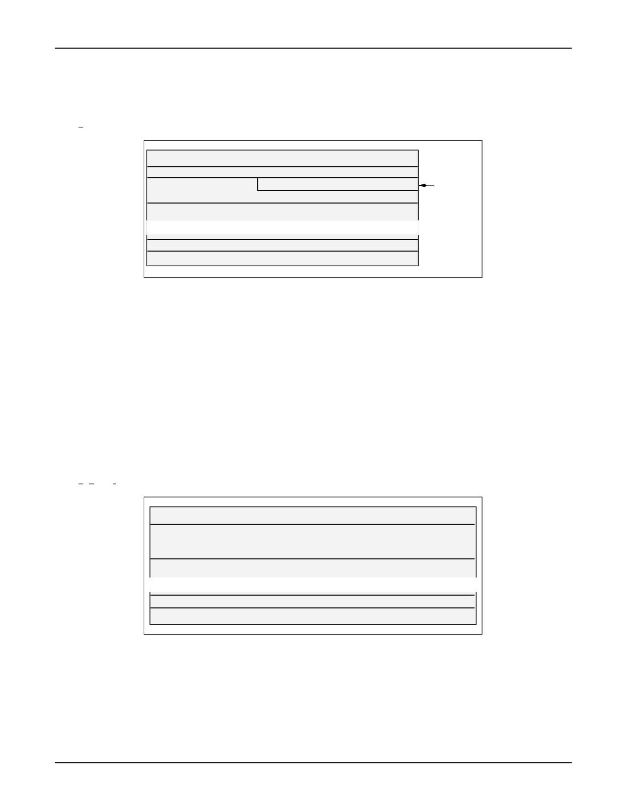
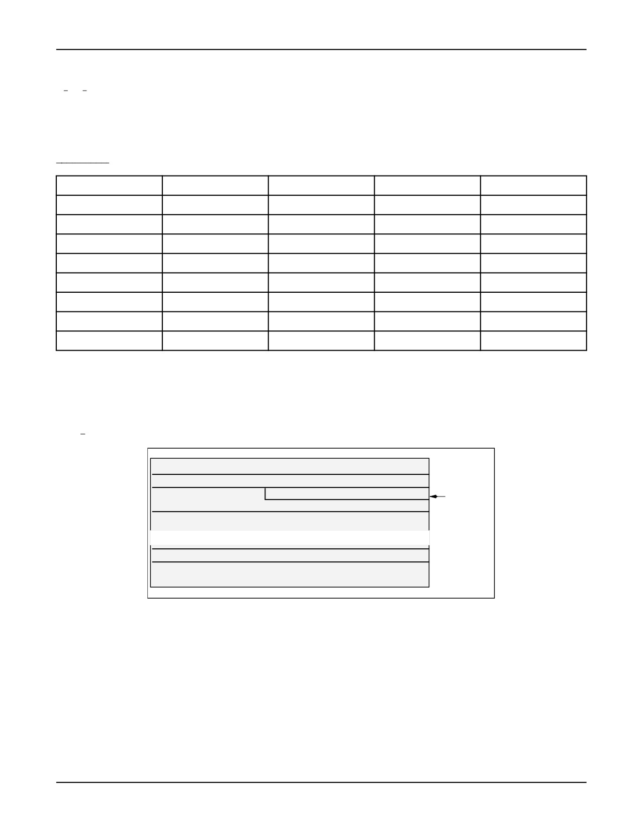
By default, the USER menu will attach the "err", "stat", "full", "motn", "t_fu", "t_pr", and "t_fk"
windows to the "t_sc" screen. See Figure 7-1 .
Figure 7-1. "t_sc" Screen
err (TPERROR)
stat
full
motn
full
motn overlaps
t_fu (TPDISPLAY)
full at
column 18
t_pr (TPPROMPT)
t_fk (TPFUNC)
The following system variables affect the teach pendant USER menu:
•
$TP_DEFPROG: STRING - Identifies the teach pendant default program. This is automatically
set when a program is selected from the teach pendant SELECT menu.
•
$TP_INUSER: BOOLEAN - Set to TRUE when the USER menu is selected from the teach
pendant.
•
$TP_LCKUSER: BOOLEAN - Locks the teach pendant in the USER menu while
$TP_DEFPROG is running and $TP_LCKUSER is TRUE.
•
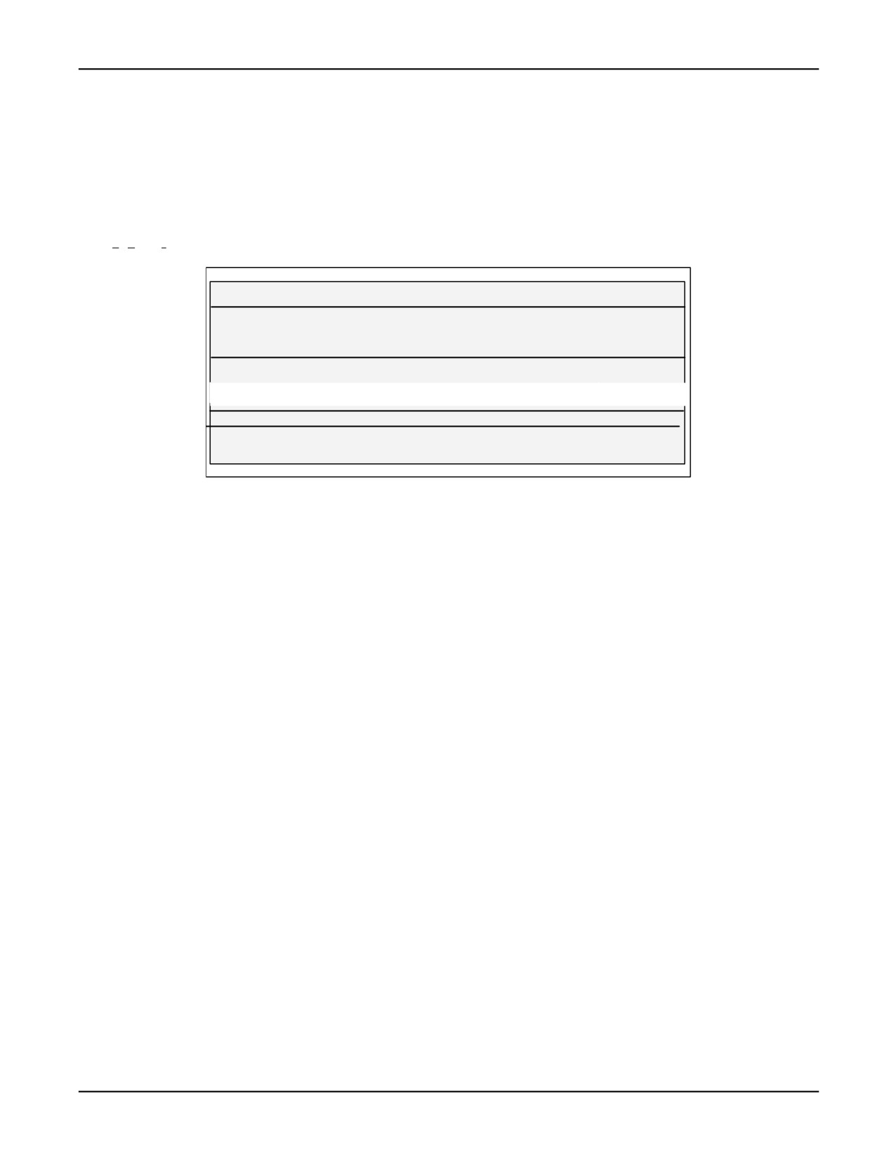
$TP_USESTAT: BOOLEAN - Causes the user status window "t_st" (TPSTATUS) to be attached
to the user screen while $TP_USESTAT is TRUE. While "t_st" is attached, the "stat", "motn", and
"full" windows will be detached. See Figure 7-2 .
Figure 7-2. "t_sc" Screen with $TP_USESTAT = TRUE
err (TPERROR)
t_st (TPSTATUS)
t_st (TPSTATUS)
t_st (TPSTATUS)
t_fu (TPDISPLAY)
t_pr (TPPROMPT)
t_fk (TPFUNC)
7-39
7. FILE INPUT/OUTPUT OPERATIONS
MARRC75KR07091E Rev D
7.10.2
USER Menu on the CRT/KB
The screen that is activated when the USER menu is selected from the CRT is named "c_sc". The
windows listed in Table 7-19 are defined for "c_sc".
Table 7-19. Defined Windows for c_sc"
Window Name
Lines
Predefined FILE Name
Scrolled
Rows
"c_fu"
17
INPUT and OUTPUT
yes
5-21
"c_pr"
1
CRTPROMPT
no
22
"c_st"
3
CRTSTATUS
no
2-4
"c_fk"
2
CRTFUNC
no
23-24
"err"
1
CRTERROR
no
1
"ct01"
1
no
2
"uful"
2
no
3-4
"motn"
1
no
3
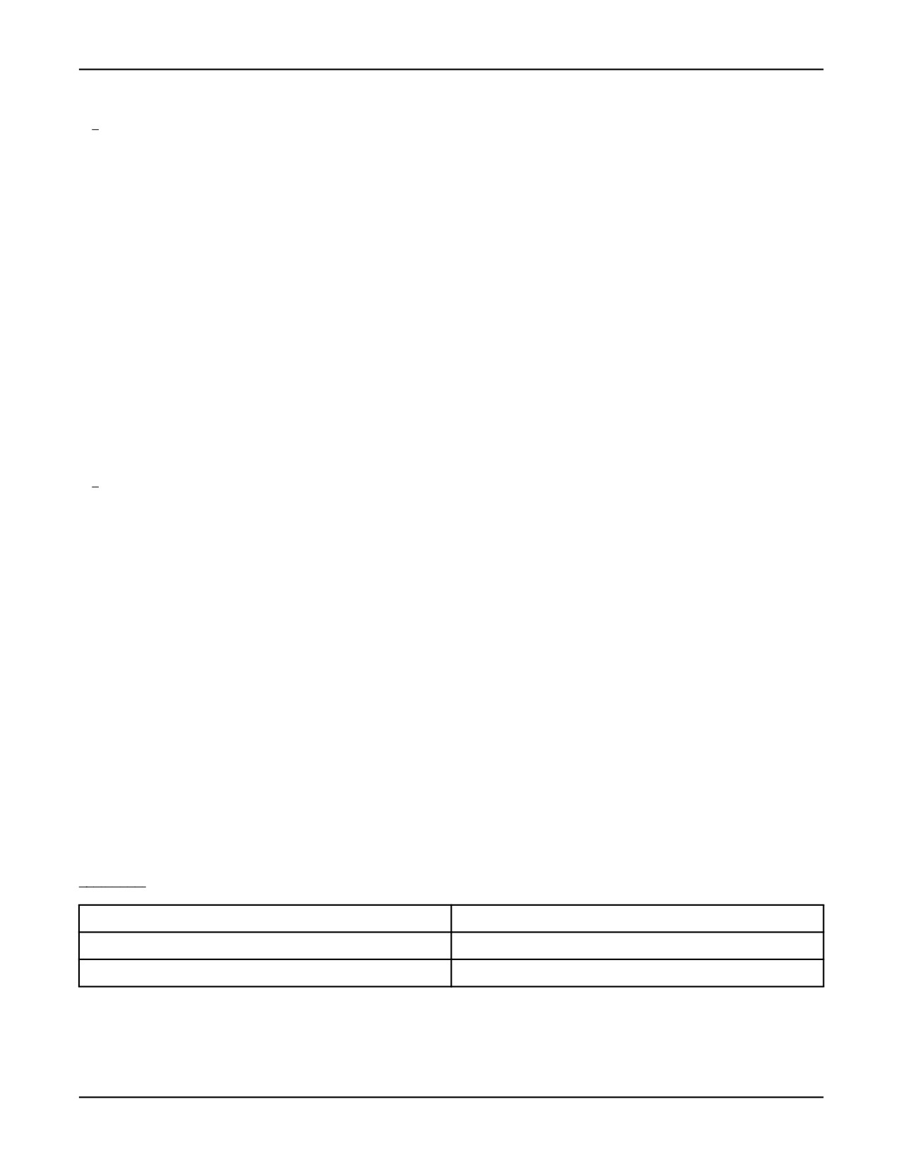
By default, the USER menu will attach the "err", "ct01", "uful", "motn", "c_fu", "c_fk", and "uftn"
windows to the "c_sc" screen. The "c_fk" window will label the function keys an show FCTN and
MENUS for F9 and F10. See Figure 7-3 .
Figure 7-3. "c_sc" Screen
err (CRTERROR)
ct01
uful
motn
uful
uful and motn
c_fu (INPUT and OUTPUT)
overlap; motn
starts at
column 18
c_pr (CRTPROMPT)
c_fk (CRTFUNC)
c_fk
The following system variables affect the CRT USER menu:
•
$CRT_DEFPROG: STRING - This variable identifies the CRT default program. This is
automatically set when a program is selected from the CRT SELECT menu.
•
$CRT_INUSER: BOOLEAN - This variable is set to TRUE when the USER menu is selected
from the CRT.
7-40
MARRC75KR07091E Rev D
7. FILE INPUT/OUTPUT OPERATIONS
•
$CRT_LCKUSER: BOOLEAN - This variable locks the CRT in the USER menu while
$CRT_DEFPROG is running and $CRT_LCKUSER is TRUE.
•
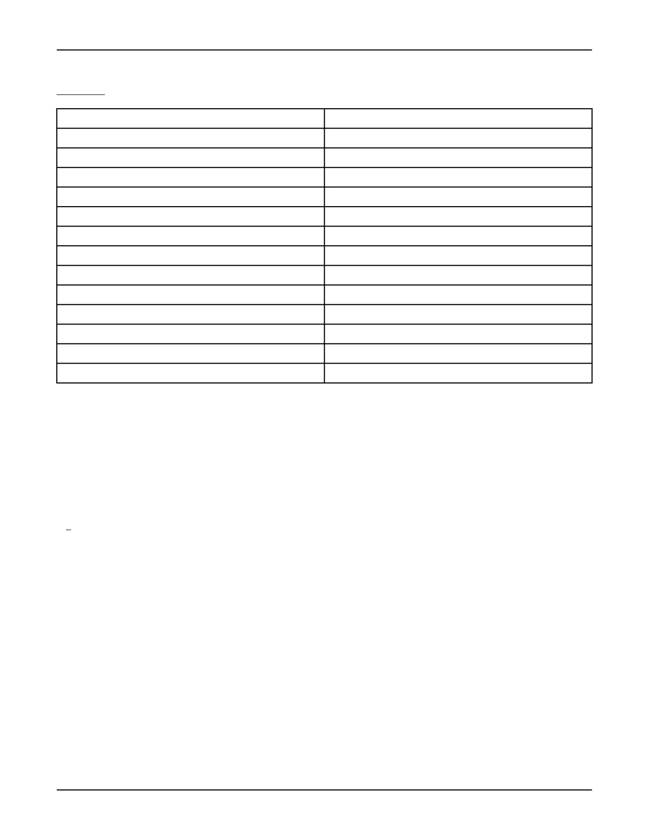
$CRT_USERSTAT: BOOLEAN - This variable causes the user status window "c_st"
(CRTSTATUS) to be attached to the user screen while $CRT_USERSTAT is TRUE. While "c_st"
is attached, the "ct01", "motn", and "uful" windows will be detached. See Figure 7-4 .
Figure 7-4. "c_sc" Screen with $CRT_USERSTAT = TRUE
err (CRTERROR)
c_st (CRTSTATUS)
c_st (CRTSTATUS)
c_st (CRTSTATUS)
c_fu (INPUT and OUTPUT)
c_pr (CRTPROMPT)
c_fk (CRTFUNC)
c_fk
7-41
Chapter 8
POSITION DATA
Contents
Chapter 8
POSITION DATA
8-1
8.1
OVERVIEW
8-2
8.2
POSITIONAL DATA
8-2
8.3
FRAMES OF REFERENCE
8-3
8.3.1
World Frame
8-4
8.3.2
User Frame (UFRAME)
8-5
8.3.3
Tool Definition (UTOOL)
8-5
8.3.4
Using Frames in the Teach Pendant Editor (TP)
8-5
8.4
JOG COORDINATE SYSTEMS
8-6
8-1
8. POSITION DATA
MARRC75KR07091E Rev D
8.1
OVERVIEW
In robotic applications, single segment motion is the movement of the tool center point (TCP) from
an initial position to a desired destination position. The KAREL system represents positional data
in terms of location (x, y, z), orientation (w, p, r), and configuration. The location and orientation
are defined relative to a Cartesian coordinate system (user frame), making them independent of the
robot joint angles. Configuration represents the unique set of joint angles at a particular location
and orientation.
Note The KAREL system provides a way to create and manipulate position data but it does not
support motion instructions. All motion must be initiated from a teach pendant program. Instructions
and builtins are available for setting KAREL position data into teach pendant programs.
8.2
POSITIONAL DATA
The KAREL language uses the POSITION, XYZWPR, XYZWPREXT, JOINTPOS, and PATH data
types to represent positional data. The POSITION data type is composed of the following:
• Three REAL values representing an x, y, z location expressed in millimeters
• Three REAL values representing a w, p, r orientation expressed in degrees
• One CONFIG Data Type, consisting of 4 booleans and 3 integers, which represent the
configuration in terms of joint placement and turn number. Before you specify the config data
type, make sure it is valid for the robot being used. Valid joint placement values include:
— ‘R’ or ‘L’ (shoulder right or left)
— ‘U’ or ‘D’ (elbow up or down)
— ‘N’ or ‘F’ (wrist no-flip or flip)
— ‘T’ or ‘B’ (config front or back)
A turn number is the number of complete turns a multiple turn joint makes beyond the
required rotation to reach a position. Table 8-1 lists the valid turn number definitions.
Table
8-1. Turn Number Definitions
Turn Number
Rotation (degrees)
-8
-2700 to -3059
-7
-2340 to -2699
8-2
MARRC75KR07091E Rev D
8. POSITION DATA
Table
8-1.
Turn Number Definitions (Cont’d)
-6
-1980 to -2339
-5
-1620 to -1979
-4
-1260 to -1619
-3
-900 to -1259
-2
-540 to -899
-1
-180 to -539
0
-179 to 179
1
180 to 539
2
540 to 899
3
900 to 1259
4
1260 to 1619
5
1620 to 1979
6
1980 to 2339
7
2340 to 2699
The PATH data type consists of a varying-length list of elements called path nodes.
See Also: The appropriate application-specific FANUC Robotics Setup and Operations Manual
for configuration information on each supported robot model. The POSITION, XYZWPR,
XYZWPREXT, JOINTPOS, and PATH Data Types, Appendix A, ‘‘KAREL Language Alphabetical
Description.’’
8.3
FRAMES OF REFERENCE
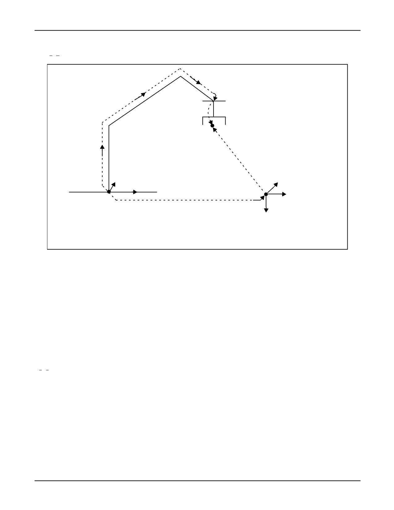
The KAREL system defines the location and orientation of positional data relative to a user-defined
frame of reference, called user frame, as shown in Figure 8-1 .
8-3
8. POSITION DATA
MARRC75KR07091E Rev D
Figure 8-1. Referencing Positions in KAREL
FACEPLATE
$UTOOL
ROBOT
TCP
POSITION
$UFRAME
WORLD
USER
COORDINATE
FRAME
SYSTEM
ROBOT = $UFRAME:POSITION:INV($UTOOL)
Three frames of reference exist:
• WORLD - predefined
• UFRAME - determined by the user
• UTOOL - defined by the tool
Using kinematic equations, the controller computes its positional information based on the known
world frame and the data stored in the system variables $UFRAME (for user frame) and $UTOOL
(for tool frame).
8.3.1
World Frame
The world frame is predefined for each robot. It is used as the default frame of reference. The location
of world frame differs for each robot model.
8-4
MARRC75KR07091E Rev D
8. POSITION DATA
8.3.2
User Frame (UFRAME)
The programmer defines user frame relative to the world frame by assigning a value to the system
variable $UFRAME.
Warning
Be sure $UFRAME is set to the same value whether you are teaching
positional data or running a program with that data, or damage to the
tool could occur.
The location of UFRAME represents distances along the x-axis, y-axis, and z-axis of the world
coordinate system; the orientation represents rotations around those axes.
By default, the system assigns a (0,0,0) location value and a (0,0,0) orientation value to $UFRAME,
meaning the user frame is identical to that of the world coordinate system. All positions are recorded
relative to UFRAME.
8.3.3
Tool Definition (UTOOL)
The tool center point (TCP) is the origin of the UTOOL frame of reference. The programmer defines
the position of the TCP relative to the faceplate of the robot by assigning a value to the system
variable $UTOOL. By default, the system assigns a (0,0,0) location and a (0,0,0) orientation to
$UTOOL, meaning $UTOOL is identical to the faceplate coordinate system. The positive z-axis of
UTOOL defines the approach vector of the tool.
Warning
Be sure $UTOOL correctly defines the position of the TCP for the tool you
are using, or damage to the tool could occur.
The faceplate coordinate system has its origin at the center of the faceplate surface. Its orientation
is defined with the plane of the x-axis and y-axis on the faceplate and the positive z-axis pointing
straight out from the faceplate.
8.3.4
Using Frames in the Teach Pendant Editor (TP)
The system variable $USEUFRAME defines whether the current value of
$MNUFRAMENUM[group_no] will be assigned to the position’s user frame when it is being
recorded or touched up.
8-5
8. POSITION DATA
MARRC75KR07091E Rev D
• When $USEUFRAME = FALSE , the initial recording of positions and the touching
up of positions is done with the user frame number equal to 0, regardless of the value of
$MNUFRAMENUM[group_no].
• When $USEUFRAME = TRUE , the initial recording of positions is done with the position’s
user frame equal to the user frame defined by $MNUFRAMENUM[group_no]. The touching up
of positions must also be done with the position’s user frame equal to the user frame defined by
$MNUFRAMENUM[group_no].
When a position is recorded in the teach pendant editor, the value of the position’s tool frame will
always equal the value of $MNUTOOLNUM[group_no] at the time the position was recorded. When
a teach pendant program is executed, you must make sure that the user frame and the tool frame of
the position equal the values of $MNUFRAMENUM[group_no] and $MNUTOOLNUM[group_no];
otherwise, an error will occur. Set the values of $MNUFRAMENUM[1] and $MNUTOOLNUM[1]
using the UFRAME_NUM = n and UTOOL_NUM = n instructions in the teach pendant editor before
you record the position to guarantee that the user and tool frame numbers match during program
execution.
8.4
JOG COORDINATE SYSTEMS
The KAREL system provides five different jog coordinate systems:
• JOINT - a joint coordinate system in which individual robot axes move. The motion is joint
interpolated.
• WORLD - a Cartesian coordinate system in which the TCP moves parallel to, or rotates around,
the x, y, and z-axes of the predefined WORLD frame. The motion is linearly interpolated.
• TOOLFRAME - a Cartesian coordinate system in which the TCP moves parallel to, or
rotates around, the x, y, and z-axes of the currently selected tool frame. The motion is linearly
interpolated. The tool frame is normally selected using the SETUP Frames menu. To jog using
$GROUP[group_no].$utool, set $MNUTOOLNUM[group_no] = 30.
• JOGFRAME - a Cartesian coordinate system in which the TCP moves parallel to, or rotates
around, the x, y, and z-axes of the coordinate system defined by the $JOG_GROUP[group
_no].$jogframe system variable. The motion is linearly interpolated.
• USER FRAME - a Cartesian coordinate system in which the TCP moves parallel to, or
rotates around, the x, y, and z-axes of the currently selected user frame. The motion is linearly
interpolated. The user frame is normally selected using the SETUP Frames menu. To jog using
$GROUP[group_no].$uframe, set $MNUFRAMENUM[group_no] = 62.
The robot can be jogged in any one of these jog coordinate systems to reach a destination position.
Once that position is reached, however, the positional data is recorded with reference to the user
frame as discussed in Section 8.3 .
See Also: The application-specific FANUC Robotics Setup and Operations Manual for step-by-step
explanations of how to jog and define frames.
8-6
Chapter 9
FILE SYSTEM
Contents
Chapter 9
FILE SYSTEM
9-1
9.1
OVERVIEW
9-2
9.2
FILE SPECIFICATION
9-3
9.2.1
Device Name
9-3
9.2.2
File Name
9-4
9.2.3
File Type
9-5
9.3
STORAGE DEVICE ACCESS
9-6
9.3.1
Overview
9-7
9.3.2
Memory File Devices
9-13
9.3.3
Virtual Devices
9-14
9.3.4
File Pipes
9-16
9.4
FILE ACCESS
9-20
9.5
FORMATTING XML INPUT
9-20
9.5.1
Overview
9-20
9.5.2
Installation Sequence
9-21
9.5.3
Example KAREL Program Referencing an XML File
9-22
9.5.4
Parse Errors
9-26
9.6
MEMORY DEVICE
9-27
9-1
9. FILE SYSTEM
MARRC75KR07091E Rev D
9.1
OVERVIEW
The file system provides a means of storing data on CMOS RAM, FROM, or external storage
devices. The data is grouped into units, with each unit representing a file. For example, a file can
contain the following:
• Source code statements for a KAREL program
• A sequence of KCL commands for a command procedure
• Variable data for a program
Files are identified by file specifications that include the following:
• The name of the device on which the file is stored
• The name of the file
• The type of data included in the file
The KAREL system includes five types of storage devices where files can be stored:
• RAM Disk
• FROM Disk
• IBM PC
• Memory Card
• USB Memory Stick Device
RAM Disk is a portion of SRAM (formerly CMOS RAM) or DRAM memory that functions as a
separate storage device. Any file can be stored on the RAM Disk. RAM Disk files should be copied
to disks for permanent storage.
FROM Disk is a portion of FROM memory that functions as a separate storage device. Any file can be
stored on the F-ROM disk. However, the hardware supports a limited number of read and write cycles.
Therefore, if a file needs to store dynamically changing data, the RAM disk should be used instead.
IBM PC or compatible computers can be used to store files off-line. You can use OLPC, the
FANUC Robotics off-line storage software for the PC, to store files on an external storage device. The
files on these storage devices are accessible in the following ways:
• Through the FILE menu on the teach pendant and CRT/KB
• Through KAREL programs
Memory Card refers to the ATA Flash File storage. The memory card interface is located on the
MAIN CPU.
For more information on storage devices and memory, refer to Section 9.3.1 .
9-2
MARRC75KR07091E Rev D
9. FILE SYSTEM
USB Memory Stick Device supports a USB 1.1 interface. The USB Organization specifies standards
for USB 1.1 and 2.0. Most memory stick devices conform to the USB 2.0 specification for operation
and electrical standards. USB 2.0 devices as defined by the USB Specification must be backward
compatible with USB 1.1 devices.
However, FANUC Robotics does not support any security or encryption features on USB memory
sticks. The controller supports most widely-available USB Flash memory sticks from 32MB up to
1GB in size. The USB interface is located on the controller operator panel.
9.2
FILE SPECIFICATION
File specifications identify files. The specification indicates:
• The name of the device on which the file is stored, refer to Section 9.2.1 .
• The name of the file, refer to Section 9.2.2 .
• The type of data the file contains, refer to Section 9.2.3 .
The general form of a file specification is:
device_name:file_name.file_type
9.2.1
Device Name
A device name consists of at least two characters that indicate the device on which a file is stored.
Files can be stored on RAM disk, F-ROM disk, disk drive units, off-line on a PC, Memory Card, or
PATH Composite Device. The device name always ends with a colon (:). The following is a list of
valid storage devices.
• RD: (RAM Disk)
The RD: device name refers to files stored on the RAM Disk of the controller. RD: is used
as the default device name.
• FR: (F-ROM Disk)
The FR: device name refers to files stored on the F-ROM disk of the controller.
• MC: (Memory Card Device)
The memory card can be formatted and used as an MS-DOS file system. It can be read from and
written to on the controller and an IBM PC equipped with the proper hardware and software. If
the memory card is used as an MS-DOS file system, it should be formatted only on the controller.
Refer to the application-specific FANUC Robotics Setup and Operations Manual for information
on formatting the memory card on the controller.
9-3
9. FILE SYSTEM
MARRC75KR07091E Rev D
•
UD1: (USB Memory Stick Device)
The USB memory stick can be formatted and used as an MS-DOS file system. It can be read from
and written to on the controller and an IBM PC equipped with the proper hardware and software.
If the USB memory stick is used as an MS-DOS file system, it should be formatted only on the
controller. Refer to the application-specific FANUC Robotics Setup and Operations Manual for
information on formatting the USB memory stick on the controller.
•
MD: (Memory Device)
The memory device treats the controller’s program memory as if it were a file device. You can
access all teach pendant programs, KAREL programs, KAREL variables, system variables, and
error logs that are loaded in the controller. See Section 9.6 for further details.
•
MDB: (Memory Device Backup)
The memory device backup device (MDB:) allows the user to copy the same files as provided by
the Backup function on the File Menu. This allows the user to back up the controller remotely.
•
CONS: (Console Device)
The console device provides access to the console log text files CONSLOG.LS and
CONSTAIL.LS. It is used for diagnostic and debug purposes and not as a storage device.
•
MF: (Memory File Device)
The MF: device name refers to files stored on both the RAM and F-ROM disks. Since a file
cannot be on both disks at the same time, there will be no duplicate file names.
•
PATH: (Composite Device)
The PATH: device is a read-only device that searches the F-ROM disk (FD:), memory card
(MC:0, and floppy disk (FLPY:) in that order, for a specified file. The PATH: device eliminates
the user’s need to know on which storage device the specified file exists.
•
PIP: (File Pipe Device)
The PIP: device provides a way to write data from one application and, at the same time, read it
from another application. The PIP: device also allows the last set of data written to be retained for
analysis. The PIP: device allows you to access any number of pipe files. This access is to files
that are in the controller’s memory. This means that the access to these files is very efficient. The
size of the files and number of files are limited by available controller memory. This means that
the best use of a file pipe is to buffer data or temporarily hold it.
9.2.2
File Name
A file name is an identifier that you choose to represent the contents of a file.
The following rules apply to file names:
9-4
MARRC75KR07091E Rev D
9. FILE SYSTEM
• File names are limited to 36 characters.
• File names can include letters, digits, and underscores.
• File names cannot include these characters: .:*;\/”’
• Spaces are not allowed in the file name.
• Other special characters can be used with caution.
• Subdirectories can be used. These are also called a “path.” These begin and end with the “\”
character. The rules for file names also apply to paths. Below is an example of a file name
with a device and a path:
MC:\mypath\myfile.txt
9.2.3
File Type
A file type consists of two or three characters that indicate what type of data a file contains. A file
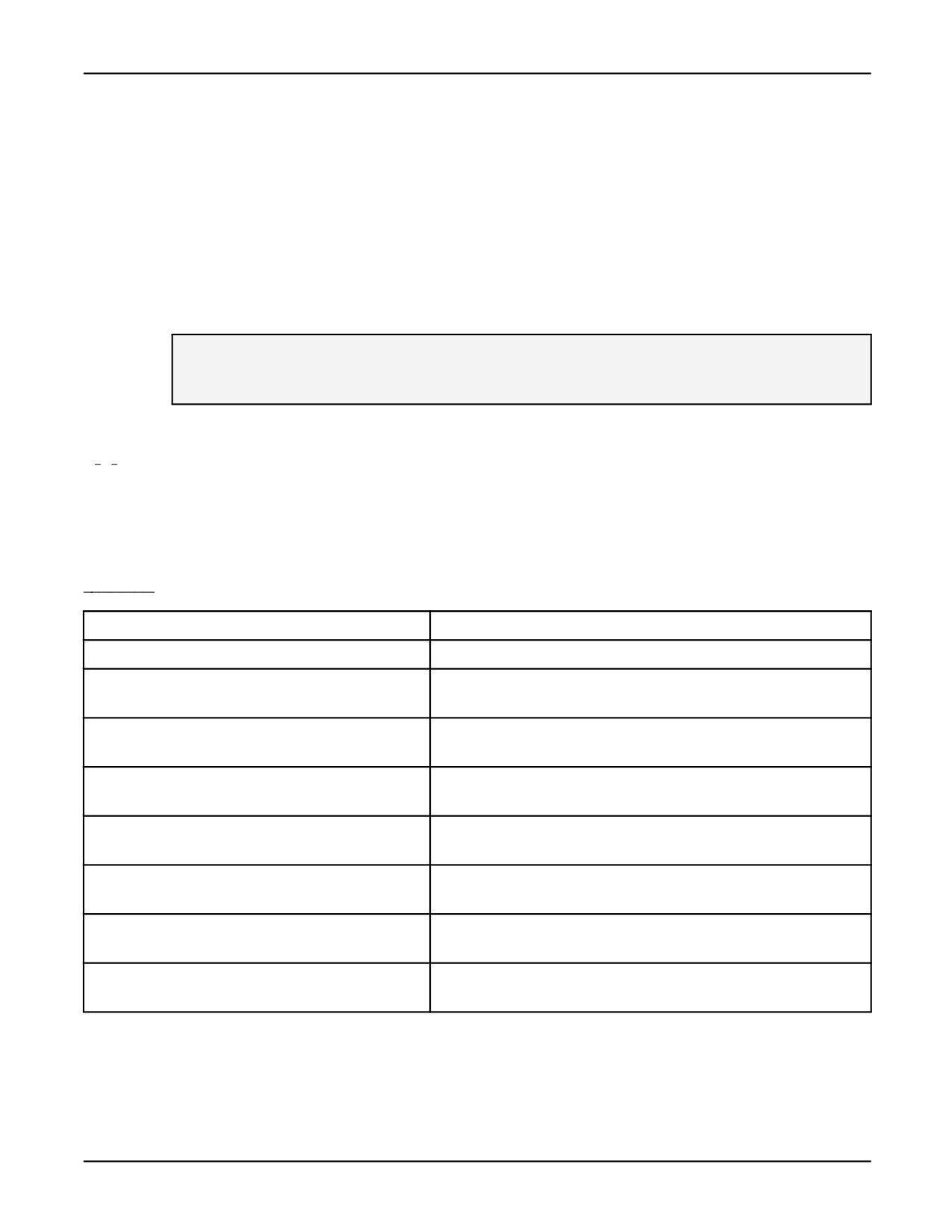
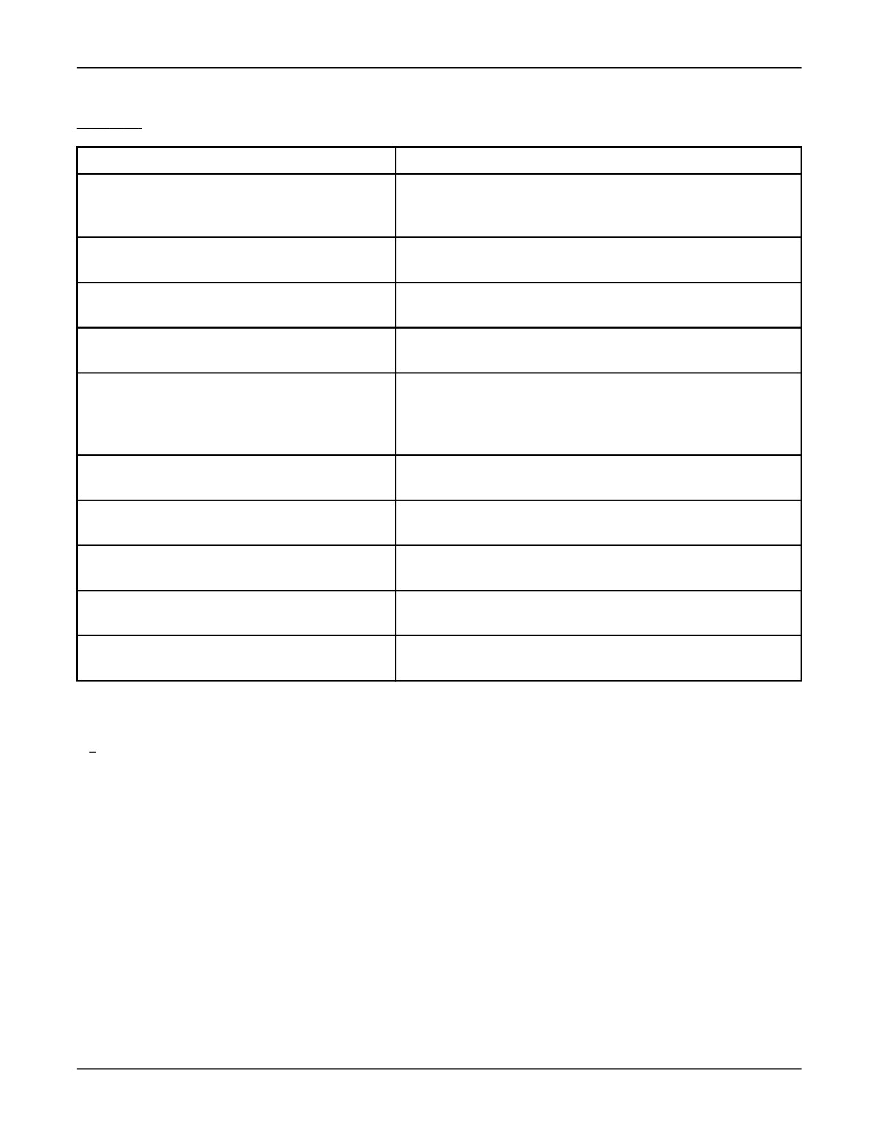
type always begins with a period (.). Table 9-1 is an alphabetical list of each available file type
and its function.
Table 9-1.
File Type Descriptions
File Type
Description
.BMP
Bit map files contain bit map images used in robot vision systems.
.CF
KCL command files are ASCII files that contain a sequence of KCL
commands for a command procedure.
.CH
Condition handler files are used as part of the condition monitor
feature.
.DF
Default file are binary files that contain the default motion
instructions for each teach pendant programming.
.DG
Diagnostic files are ASCII files that provide status or diagnostic
information about various functions of the controller.
.DT
KAREL data file An ASCII or binary file that can contain any data
that is needed by the user.
.IO
Binary files that contain I/O configuration data - generated when an
I/O screen is displayed and the data is saved.
.KL
KAREL source code files are ASCII files that contain the KAREL
language statements for a KAREL program.
9-5
9. FILE SYSTEM
MARRC75KR07091E Rev D
Table 9-1.
File Type Descriptions (Cont’d)
File Type
Description
.LS
KAREL listing files are ASCII files that contain the listing of
a KAREL language program and line number for each KAREL
statement.
.MN
Mnemonic program files are supported in previous version s of
KAREL.
.ML
Part model files contain part model information used in robot vision
systems.
.PC
KAREL p-code files are binary files that contain the p-code
produced by the translator upon translation of a .KL file.
.SV
System files are binary files that contain data for tool and user
frames (SYSFRAME.SV), system variables (SYSVARS.SV),
mastering (SYSMAST.SV), servo parameters (SYSSERVO.SV), and
macros (SYSMACRO.SV).
.TP
Teach pendant program files are binary files that contain
instructions for teach pendant programs.
.TX
Text files are ASCII files that can contain system-defined text or
user-defined text.
.VR
Program variable files are binary files that contain variable data for
a KAREL program.
.VA
ASCII variable files are contain the listing of a variable file with
variable names, types, and contents.
.LS
Listing files are teach pendant programs, error logs, and description
histories in ASCII format.
9.3
STORAGE DEVICE ACCESS
The KAREL system can access only those storage devices that have been formatted and mounted.
These procedures are performed when the devices are first installed on the KAREL system.
The following rules apply when accessing storage devices:
• Formatting a device
— Deletes any existing data on the device. For example, if you format RD2:, you will also
reformat any data existing on RD: thru RD7:.
— Records a directory on the device
— Records other data required by the KAREL system
9-6
MARRC75KR07091E Rev D
9. FILE SYSTEM
— Assigns a volume name to the device
For more information on formatting a device, refer to the FORMAT_DEV Built-in in Appendix A ,
"KAREL Language Alphabetical Description" or the FORMAT Command in Appendix C , "KCL
Command Alphabetical Description."
9.3.1
Overview
The following kinds of storage devices can be used to store programs and files:
• Memory Card (MC:)
• Flash File Storage disk (FR:)
• RAM Disk (RD:) (Not for SpotTool+)
• Ethernet Device (optional)
• Memory Device (MD:)
• Memory Device Binary (MDB:)
• Filtered Memory Device (FMD:)
• USB Memory Stick Device on the controller (UD1:)
• USB Memory Stick Device on the iPendant (UT1:)
This section describes how to set up storage devices for use. Depending on the storage device, this
can include
• Setting up a port on the controller
• Connecting the device to the controller
• Formatting a device
Memory Card (MC:)
The controller supports memory cards. Memory cards support various sizes 8MB or higher. Compact
Flash PC cards are also supported if used with a suitable compact adapter. The memory card requires
a memory card interface which is standard on Main CPU inside the controller.
Note The controller supports loading software from memory cards.
9-7
9. FILE SYSTEM
MARRC75KR07091E Rev D
Warning
Lethal voltage is present in the controller WHENEVER IT IS CONNECTED
to a power source. Be extremely careful to avoid electrical shock. HIGH
VOLTAGE IS PRESENT at the input side whenever the controller is
connected to a power source. Turning the disconnect or circuit breaker to
the OFF position removes power from the output side of the device only.
Warning
The memory card interface is located on the Main CPU on the controller
cabinet. When the power disconnect circuit breaker is OFF, power is
still present inside the controller. Turn off the power disconnect circuit
breaker before you insert a memory card into the memory card interface;
otherwise, you could injure personnel.
Caution
Do not remove the memory card when the controller is reading or writing to it.
Doing so could damage the card and lose all information stored on it.
The memory card can be formatted on the controller, and can be used as a load device to install
software.
Note Data on all internal file devices such as FR:, RD:, and MD: should be backed up to external file
device such as ATA Flash PC card.
Note The controller formats the card with a sector size of 512 bytes.
The memory card can be formatted and used as an MS-DOS file system. It can be read from and
written to the controller and an IBM PC equipped with the proper hardware and software. If the
memory card is used as an MS-DOS file system, it should be formatted on the controller.
The controller can read and write memory cards that are formatted with FAT (also referred to as
FAT16) or FAT32 type of formatting (File Access Tables). When a memory card is formatted on the
Controller it can be formatted as FAT or FAT32 type.
The FAT32 format (32 Bit FAT) removes a few limitations that are included with FAT. One of these is
the limitation that only 512 files can be created in the Root directory. Another is that FAT format type
only supports memory cards up to 2 GB in size. This feature is included in the controller to increase
the compatibility of the robot controller with other computer systems.
9-8
MARRC75KR07091E Rev D
9. FILE SYSTEM
USB Memory Stick Device on the controller (UD1:), and USB Memory Stick Device
on the iPendant (UT1:)
The controller supports USB Flash memory sticks up to 2GB in size if it is formatted as FAT16.
FAT16 is much faster for access. USB Memory sticks with any security or encryption features are
not supported. Memory sticks larger than 2GB can not be formatted FAT16, they must be formatted
FAT32.
Note USB Memory sticks cannot be formatted when plugged into the USB connector on the iPendant
(UT1:) They must be formatted on a PC or when plugged into the front panel USB connector on the
controller.
Note USB Memory sticks with any security or encryption features are not supported.
Note Memory sticks larger than 2GB can not be formatted FAT16, they must be formatted FAT32.
Note Generally the larger the size of the device such as a USB memory stick, the slower the access
speed and device performance. A USB memory stick should be formatted FAT16 if possible. Larger
memory sticks formatted as FAT32 will work, but will be slower for file operations and startup of the
memory stick when it is first inserted.
Note In order to use the UT: device on the iPendant, you must have the USB Port on iPendant
option (J957) installed.
Note Since USB is a well established specification, FANUC Robotics America Corporation does
not qualify specific USB Memory sticks for use with the robot. FANUC Robotics uses USB Flash
drives manufactured by SanDisk® (CRUZER Mini and Micro) to qualify the operation of the USB
interface. Therefore, FANUC Robotics recommends that you use SanDisk® USB Flash Drives,
without security or encryption features. Other drives might work properly but are not specifically
qualified by FANUC Robotics.
The USB Memory Stick Device requires a USB interface which is standard on the controller.
The USB memory stick device can be formatted on the controller.
Caution
Do not remove the memory stick when the controller is reading or writing to it.
Doing so could damage the memory stick and lose all information stored on it.
Flash File Storage Disk (FR:)
Flash File Storage Disk is a portion of FROM memory that functions as a separate storage device.
Flash file storage disk (FR:) does not require battery backup for information to be retained. You can
store the following information on Flash file storage disk:
• Programs
9-9
9. FILE SYSTEM
MARRC75KR07091E Rev D
• System variables
• Anything you can save as a file
You can format the Flash file storage disk. The size of the Flash file storage disk is set by the system
at software installation. Due to the nature of FROM, each time you copy or save a file to the FR: there
will be a drop in available FR: memory, even if you are working with the same file.
RAM Disk (Not for SpotTool+)
RAM Disk is a portion of Static RAM (SRAM) or DRAM memory that functions as a separate
storage device. Any file can be stored on the RAM Disk. RAM Disk files should be copied to an
external device for permanent storage.
The location and size of the RAM disk (RD:) depends on the value of the system variable
$FILE_MAXSEC. The default value of $FILE_MAXSEC depends on the options and tool packages
that are installed.
The value in $FILE_MAXSEC represents the memory size allocated for RD: in 512 byte sectors. For
example, a value of -128 means that 64K of memory is allocated in DRAM for RD:.
• If $FILE_MAXSEC > 0 , then RAM disk is defined to be in the PERM pool of SRAM. Because
RAM disk is a portion of SRAM, copy all RAM disk files to an external device for permanent
storage to prevent losing information due to loss of battery power or system software loading.
SRAM is battery-backed volatile memory. This means that all information in SRAM, including
programs, requires battery backup for information to be retained when the controller is turned
off and then on again. Teach pendant programs are automatically stored in the TPP pool of
SRAM when you write a program.
Caution
Data in SRAM can be lost if the battery is removed or loses its charge, or if
new system software is loaded on the controller. To prevent loss of data,
back up or copy all files to permanent storage devices such as FR: or ATA
Flash PC memory cards.
• If $FILE_MAXSEC < 0 , then RAM disk is defined to be in DRAM.
DRAM is non-battery-backed volatile memory. This means that all information in DRAM
disappears between power cycles. In effect, DRAM is a temporary device. Information stored in
DRAM is lost when you turn off the controller.
9-10
MARRC75KR07091E Rev D
9. FILE SYSTEM
Caution
Data in DRAM will be lost if you turn off the controller or if the controller loses
power. Do not store anything you want to save beyond the next controller
power cycle in DRAM, otherwise, you will lose it.
Note Volatile means the memory is lost when power is disconnected. Non-volatile memory does
not require battery power to retain.
You can store anything that is a file on the RAM Disk. The RAM disk is already formatted for you.
Information stored on RAM disk can be stored as compressed or uncompressed. By default,
information is compressed. If you want information to remain uncompressed, you must use the RDU:
device designation to indicate that information will be saved to that device in an uncompressed
file format.
FTP Ethernet Device
FTP Ethernet devices are used to copy files from the controller to the network PC or workstation if the
FTP option is installed. The client devices displayed are the client devices that have been defined and
started. Refer to the Internet Options Setup and Operations Manual for more information.
Memory Device (MD:)
The memory device (MD:) treats the controller’s program memory as if it were a file device. You can
access all teach pendant programs, KAREL programs, and KAREL variables loaded in the controller.
The Memory Device is a group of devices (MD:, MDB:, and optionally FMD:) that provide the
following :
• MD: provides access to ASCII and binary versions of user setup and programs
• MDB: provides access to binary versions of user setup and programs (similar to "backup - all of
the above" on the teach pendant file menu)
• FMD: provides access to ASCII versions of user setup and programs filtered to include only user
settable information (eg. internal timers or time system variables changed by the system are not
included) making these files useful for detecting user changes.
Memory Device Binary (MDB:)
The memory device binary device (MDB:) allows you to copy the same files as provided by the
Backup function on the File Menu. This allows you to back up the controller remotely such as from
9-11
9. FILE SYSTEM
MARRC75KR07091E Rev D
SMON, FTP, or KCL. For example, you could use the MDB: device to copy all teach pendant files
(including invisible files) to the memory card (KCL>copy MDB:*.tp TO mc:).
Filtered Memory Device (FMD:)
The Filtered Memory Device option generates text versions of all backup files of user programs and
variables that have been changed manually. Included are system and KAREL variables, position and
data registers, teach pendant programs, and I/O configuration data.
When logging into the robot FTP server from a remote client you are defaulted into the MD: device.
You can navigate to other robot file devices (FR:, RD:, MC:, MDB:, FMD:) using the change directory
service in your remote FTP client. At a command line using the cd command where in this example
fmd: is the device being used, this might look like :
D:\temp>ftp pderob029
Connected to pderob029.frc.com
220 FTP server ready.
[PaintTool Vx.xxP/01]
User <pderob029.frc.com:<none>>:
230 User logged in [NORM].
ftp>cd fmd:
250 CWD command successful.
ftp>
You can compare these files with previous versions to determine what users or operators have
changed. Variables and programs that change without user input are filtered out, and will appear in
filter exclusion files.
After the option is installed, it will run automatically whenever you perform an Ethernet backup of the
controller from the FMD: device. After you install the Filtered Memory Device option, any of the
following filter exclusion files could appear on the FR: device.
Caution
Do not delete these files, or filter exclusion data will be lost.
• FR:SVAREEG.DT
• FR:KVAREEG.DT
• FR:POSREEG.DT
• FR:REGEEG.DT
• FR:TPLINEEG.DT
You can view program, variable, or filter exclusion files via KCL. For example:
9-12
MARRC75KR07091E Rev D
9. FILE SYSTEM
KCL> DIR FMD:*.*.
Note Computer systems that perform periodic backups could be modified to use the FMD: device
instead of the MD: device for some compare operations, for example. Contact FANUC Robotics
for more information.
FRA:
There is a special area for Automatic Backup in the controller F-ROM (FRA:). You do not need
an external device to use Automatic Backup, but a memory card can also be used. Refer to your
application-specific Setup and Operations Manual for more information.
9.3.2
Memory File Devices
The RAM and F-ROM disks allocate files using blocks. Each block is 512 bytes.
The system variable $FILE_MAXSEC specifies the number of blocks to allocate for the RAM disk. If
the specified number is less than zero, the RAM disk is allocated from DRAM. If it is greater than
zero, RAM disk is allocated from CMOS RAM. To change the number of blocks to allocate for the
RAM disk, perform the following steps from the KCL prompt:
1. Backup all files on the RAM disk. For more information on how to back up files, refer to
Chapter 8, "Program and File Manipulation" in the appropriate application-specific FANUC
Robotics Setup and Operations Manual .
2. Enter DISMOUNT RD:
KCL>DISMOUNT RD:
3. Enter SET VAR $FILE_MAXSEC
KCL>SET VAR
$FILE_MAXSEC = <new value>
4. Enter FORMAT RD:
KCL>FORMAT RD:
9-13
9. FILE SYSTEM
MARRC75KR07091E Rev D
All files will be removed from the RAM Disk when the format is performed.
5. Enter MOUNT RD:
KCL>MOUNT RD:
The RAM disk will be reformatted automatically on INIT start.
The F-ROM disk can only be formatted from the BootROM because the system software also resides
on F-ROM. The number of blocks available is set by the system. The hardware supports a limited
number of read and write cycles, so while the F-ROM disk will function similar to the RAM disk, it
does not erase files that have been deleted or overwritten.
After some use, the F-ROM disk will have used up all blocks. At that time, a purge is required to
erase the F-ROM blocks which are no longer needed. For more information on purging, refer to
the PURGE_DEV Built-in in Appendix A , "KAREL Language Alphabetical Descriptions" or the
PURGE Command in Appendix C , "KCL Command Alphabetical Description."
For more information on memory, refer to Section 1.4.1 .
9.3.3
Virtual Devices
KAREL Virtual Devices are similar to DOS subdirectories. For example
• In DOS, to access a file in a subdirectory, you would view FR:\FR1:\>test.kl .
• In KAREL, to access the same file in a virtual device, you would view FR1:test.kl .
The controller supports 7 virtual devices. A number, which identifies the virtual device, is appended
to the device name (FR 1 :). Table 9-2 shows some of the valid virtual devices available.
Table 9-2. Virtual Devices
Device Name
Actual Storage
RD:
RAM disk
FR:
F-ROM disk - compressed and uncompressed files
MF:
Refers to files on both RD: and FR:
RD1: - RD7:
RAM disk - compressed and uncompressed files
9-14