FANUC Series Series 16i-TB, Series 18i-TB, Series 160i-TB, Series 180i-TB. OPERATOR’S MANUAL - page 13

B-63524EN/01
PROGRAMMING
15. CUSTOM MACRO
NOTE
For the status-triggered and edge-triggered schemes, see
Item “Custom macro interrupt signal (UINT)” of Subsec.
16.11.2.
15.11.2
Details of Functions
Explanations
D ubprogram-type
There are two types of custom macro interrupts: Subprogram-type
interrupt and macro-type
interrupts and macro-type interrupts. The interrupt type used is selected
interrupt
by MSB (bit 5 of parameter 6003).
(a) Subprogram-type interrupt
An interrupt program is called as a subprogram. This means that the
levels of local variables remain unchanged before and after the
interrupt. This interrupt is not included in the nesting level of
subprogram calls.
(b) Macro-type interrupt
An interrupt program is called as a custom macro. This means that
the levels of local variables change before and after the interrupt. The
interrupt is not included in the nesting level of custom macro calls.
When a subprogram call or a custom macro call is performed within
the interrupt program, this call is included in the nesting level of
subprogram calls or custom macro calls. Arguments cannot be passed
from the current program even when the custom macro interrupt is a
macro-type interrupt.
D M codes for custom
In general, custom macro interrupts are controlled by M96 and M97.
macro interrupt control
However, these M codes, may already being used for other purposes (such
as an M function or macro M code call) by some machine tool builders.
For this reason, MPR (bit 4 of parameter 6003) is provided to set M codes
for custom macro interrupt control.
When specifying this parameter to use the custom macro interrupt control
M codes set by parameters, set parameters 6033 and 6034 as follows:
Set the M code to enable custom macro interrupts in parameter 6033, and
set the M code to disable custom macro interrupts in parameter 6034.
When specifying that parameter-set M codes are not used, M96 and M97
are used as the custom macro control M codes regardless of the settings
of parameters 6033 and 6034.
The M codes used for custom macro interrupt control are processed
internally (they are not output to external units). However, in terms of
program compatibility, it is undesirable to use M codes other than M96
and M97 to control custom macro interrupts.
D Custom macro interrupts
When performing a custom macro interrupt, the user may want to
and NC statements
interrupt the NC statement being executed, or the user may not want to
perform the interrupt until the execution of the current block is completed.
MIN (bit 2 of parameter 6003) is used to select whether to perform
interrupts even in the middle of a block or to wait until the end of the
block.
339
15. CUSTOM MACRO
PROGRAMMING
B-63524EN/01
S
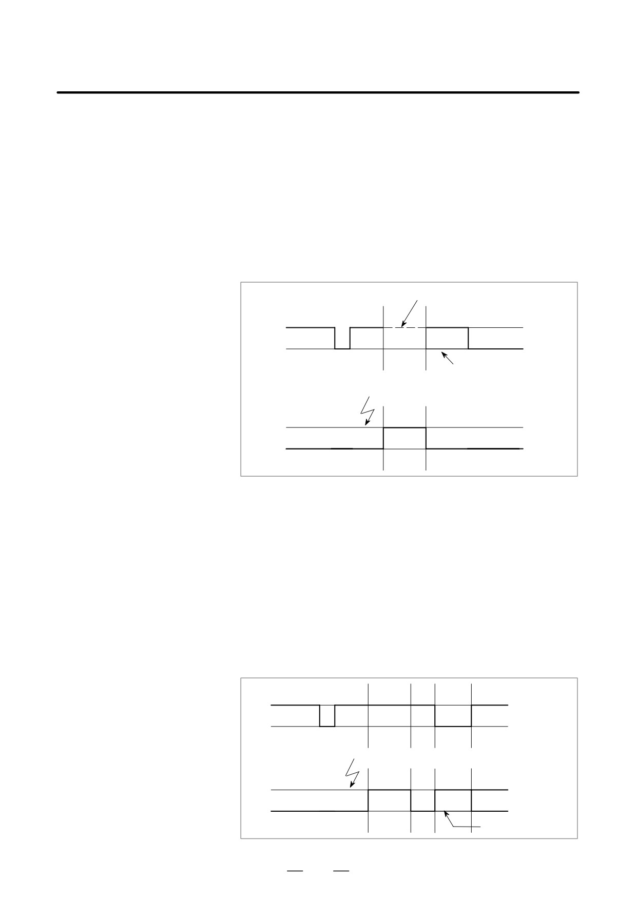
Type I
(i) When the interrupt signal (UINT) is input, any movement or dwell
(when an interrupt is
being performed is stopped immediately and the interrupt program is
performed even in the
executed.
middle of the block)
(ii) If there are NC statements in the interrupt program, the command in
the interrupted block is lost and the NC statement in the interrupt
program is executed. When control is returned to the interrupted
program, the program is restarted from the next block after the
interrupted block.
(iii)If there are no NC statements in the interrupt program, control is
returned to the interrupted program by M99, then the program is
restarted from the command in the interrupted block.
Interrupted by macro interrupt
Execution in
progress
ÉÉÉÉ
ÉÉÉÉ
Normal program
ÉÉÉÉ
CNC command restart; when
there are no NC statements
Interrupt signal (UINT) input
in the interrupt program
Execution in
progress
Custom macro
interrupt
S
Type II
(i)
If the block being executed is not a block that consists of several cycle
(when an interrupt is
operations such as a drilling canned cycle and automatic reference
performed at the end of
position return (G28), an interrupt is performed as follows:
the block)
When an interrupt signal (UINT) is input, macro statements in the
interrupt program are executed immediately unless an NC statement
is encountered in the interrupt program. NC statements are not
executed until the current block is completed.
(ii)
If the block being executed consists of several cycle operations, an
interrupt is performed as follows:
When the last movement in the cycle operations is started, macro
statements in the interrupt program are executed unless an NC
statement is encountered. NC statements are executed after all cycle
operations are completed.
Execution in
progress
Normal program
Interrupt signal (UINT) input
Execution in
progress
ÉÉÉ
Custom macro
ÉÉÉ
NC statement in the
interrupt
interrupt program
340
B-63524EN/01
PROGRAMMING
15. CUSTOM MACRO
D Conditions for enabling
The interrupt signal becomes valid after execution starts of a block that
and disabling the custom
contains M96 for enabling custom macro interrupts. The signal becomes
macro interrupt signal
invalid when execution starts of a block that contains M97.
While an interrupt program is being executed, the interrupt signal
becomes invalid. The signal become valid when the execution of the
block that immediately follows the interrupted block in the main program
is started after control returns from the interrupt program. In type I, if the
interrupt program consists of only macro statements, the interrupt signal
becomes valid when execution of the interrupted block is started after
control returns from the interrupt program.
D Custom macro interrupt
during execution of a
block that involves cycle
operation
S For type I
Even when cycle operation is in progress, movement is interrupted, and
the interrupt program is executed. If the interrupt program contains no
NC statements, the cycle operation is restarted after control is returned to
the interrupted program. If there are NC statements, the remaining
operations in the interrupted cycle are discarded, and the next block is
executed.
S For type II
When the last movement of the cycle operation is started, macro
statements in the interrupt program are executed unless an NC statement
is encountered. NC statements are executed after cycle operation is
completed.
341
15. CUSTOM MACRO
PROGRAMMING
B-63524EN/01
D Custom macro interrupt
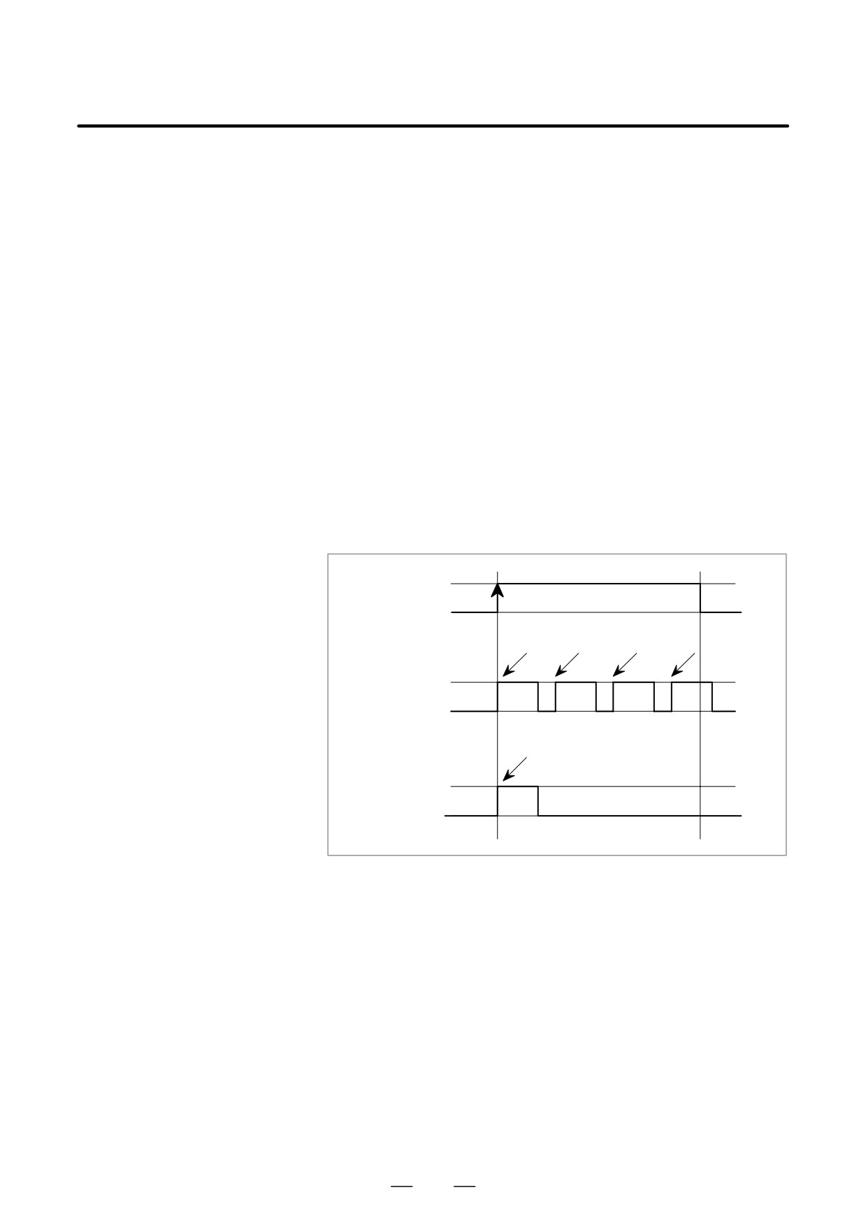
There are two schemes for custom macro interrupt signal (UINT) input:
signal (UINT)
The status-triggered scheme and edge- triggered scheme. When the
status-triggered scheme is used, the signal is valid when it is on. When
the edge triggered scheme is used, the signal becomes valid on the rising
edge when it switches from off to on status.
One of the two schemes is selected with TSE (bit 3 of parameter 6003).
When the status-triggered scheme is selected by this parameter, a custom
macro interrupt is generated if the interrupt signal (UINT) is on at the time
the signal becomes valid. By keeping the interrupt signal (UINT) on, the
interrupt program can be executed repeatedly.
When the edge-triggered scheme is selected, the interrupt signal (UINT)
becomes valid only on its rising edge. Therefore, the interrupt program
is executed only momentarily (in cases when the program consists of only
macro statements). When the status-triggered scheme is inappropriate,
or when a custom macro interrupt is to be performed just once for the
entire program (in this case, the interrupt signal may be kept on), the
edge-triggered scheme is useful.
Except for the specific applications mentioned above, use of either
scheme results in the same effects. The time from signal input until a
custom macro interrupt is executed does not vary between the two
schemes.
1
0
Interrupt signal (UINT)
Interrupt Interrupt Interrupt
Interrupt
execution execution execution
execution
Status-triggered
scheme
Interrupt
execution
Edge-triggered
scheme
In the above example, an interrupt is executed four times when the status
triggered scheme is used; when the edge- triggered scheme is used, the
interrupt is executed just once.
342
B-63524EN/01
PROGRAMMING
15. CUSTOM MACRO
D Return from a custom
To return control from a custom macro interrupt to the interrupted
macro interrupt
program, specify M99. A sequence number in the interrupted program
can also be specified using address P. If this is specified, the program is
searched from the beginning for the specified sequence number. Control
is returned to the first sequence number found.
When a custom macro interrupt program is being executed, no interrupts
are generated. To enable another interrupt, execute M99. When M99 is
specified alone, it is executed before the preceding commands terminate.
Therefore, a custom macro interrupt is enabled for the last command of
the interrupt program. If this is inconvenient, custom macro interrupts
should be controlled by specifying M96 and M97 in the program.
When a custom macro interrupt is being executed, no other custom macro
interrupts are generated; when an interrupt is generated, additional
interrupts are inhibited automatically. Executing M99 makes it possible
for another custom macro interrupt to occur. M99 specified alone in a
block is executed before the previous block terminates. In the following
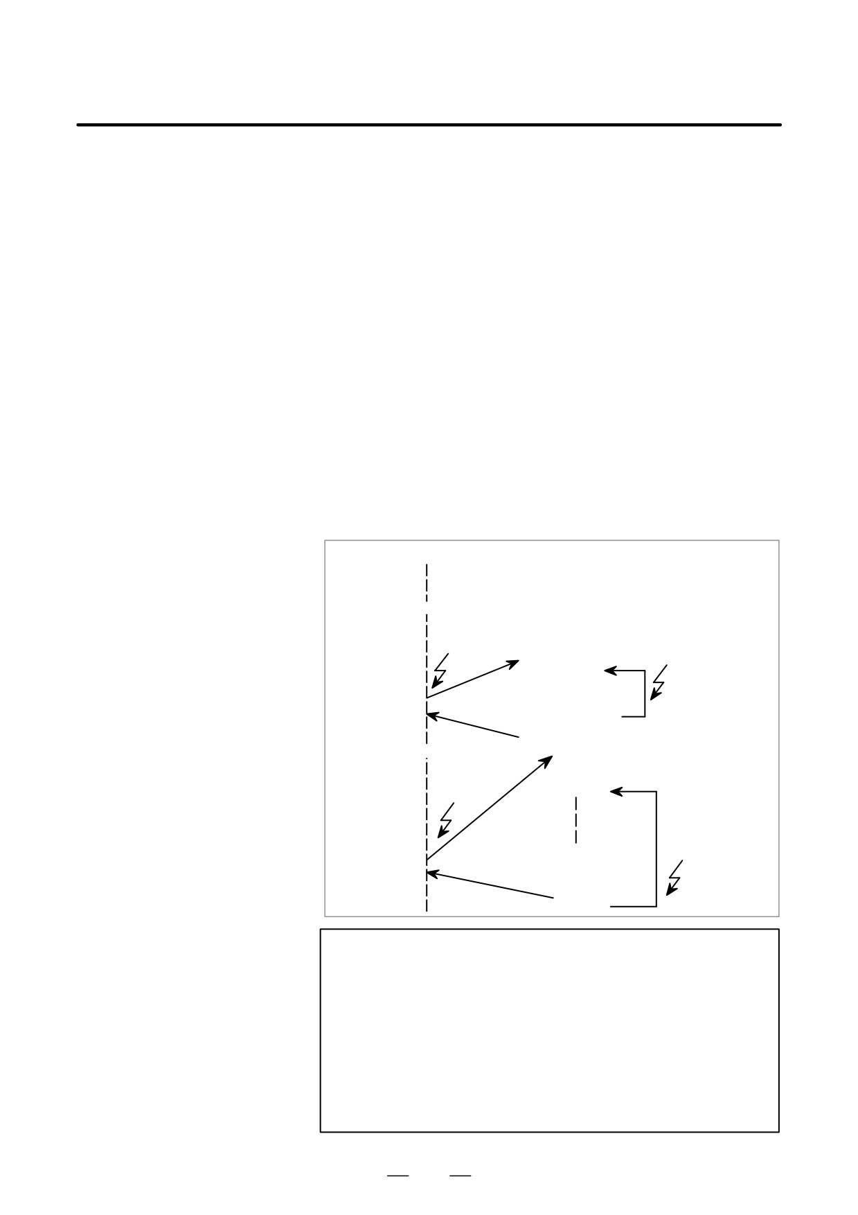
example, an interrupt is enabled for the Gxx block of O1234. When the
signal is input, O1234 is executed again. O5678 is controlled by M96 and
M97. In this case, an interrupt is not enabled for O5678 (enabled after
control is returned to O1000).
O1000;
M96P1234;
Interrupt
Interrupt
O1234
GxxXxxx;
M99;
M96P5678
O5678
M97
Interrupt
×
GxxXxxx;
Interrupt
M96;
M99;
M97
NOTE
When an M99 block consists only of address O, N, P, L, or
M, this block is regarded as belonging to the previous block
in the program. Therefore, a single-block stop does not
occur for this block. In terms of programming, the following
(1) and (2) are basically the same.
(The difference is
whether Gff is executed before M99 is recognized.)
(1) Gff Xfff ;
M99 ;
(2) Gff Xfff M99 ;
343
15. CUSTOM MACRO
PROGRAMMING
B-63524EN/01
D Custom macro interrupt
A custom macro interrupt is different from a normal program call. It is
and modal information
initiated by an interrupt signal (UINT) during program execution. In
general, any modifications of modal information made by the interrupt
program should not affect the interrupted program.
For this reason, even when modal information is modified by the interrupt
program, the modal information before the interrupt is restored when
control is returned to the interrupted program by M99.
When control is returned from the interrupt program to the interrupted
program by M99 Pxxxx, modal information can again be controlled by
the program. In this case, the new continuous information modified by
the interrupt program is passed to the interrupted program. Restoration
of the old modal information present before the interrupt is not desirable.
This is because after control is returned, some programs may operate
differently depending on the modal information present before the
interrupt. In this case, the following measures are applicable:
(1) The interrupt program provides modal information to be used after
control is returned to the interrupted program.
(2) After control is returned to the interrupted program, modal
information is specified again as necessary.
O∆∆∆∆
Interrupt signal (UINT)
M96Pxxx
Oxxx;
Modify modal information
(Without P specification)
Modal
information remains
M99(Pffff);
unchanged before and
after the interrupt.
(With P specification)
Nffff;
The new modal information modified by the inter-
rupt program is present.
S Modal information
The modal information present before the interrupt becomes valid. The
when control is
new modal information modified by the interrupt program is made
returned by M99
invalid.
S Modal information
The new modal information modified by the interrupt program remains
when control is
valid even after control is returned. The old modal information which was
returned by M99
valid in the interrupted block can be read using custom macro system
Pffff
variables #4001 to #4120.
Note that when modal information is modified by the interrupt program,
system variables #4001 to #4120 are not changed.
344
B-63524EN/01
PROGRAMMING
15. CUSTOM MACRO
D System variables
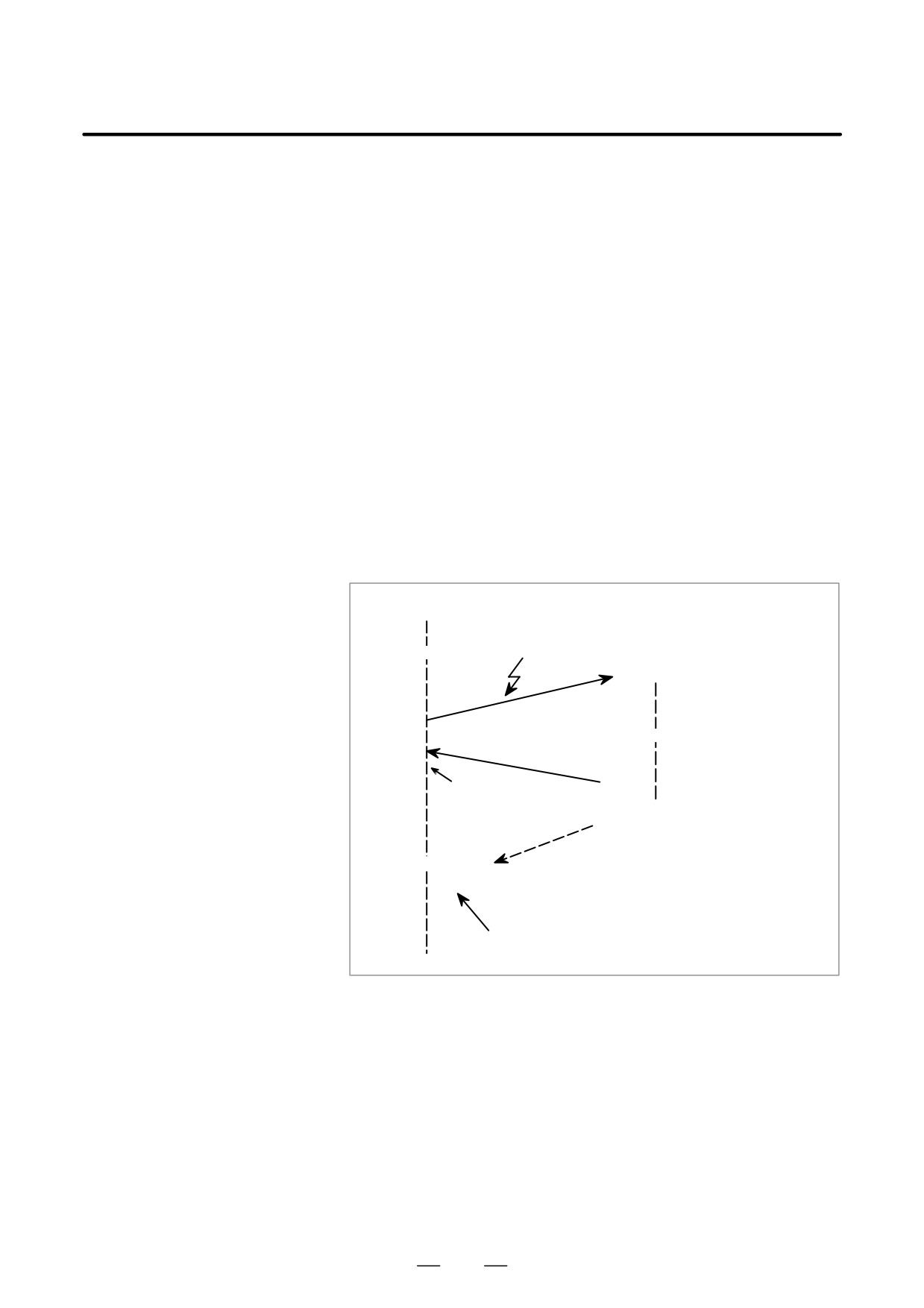
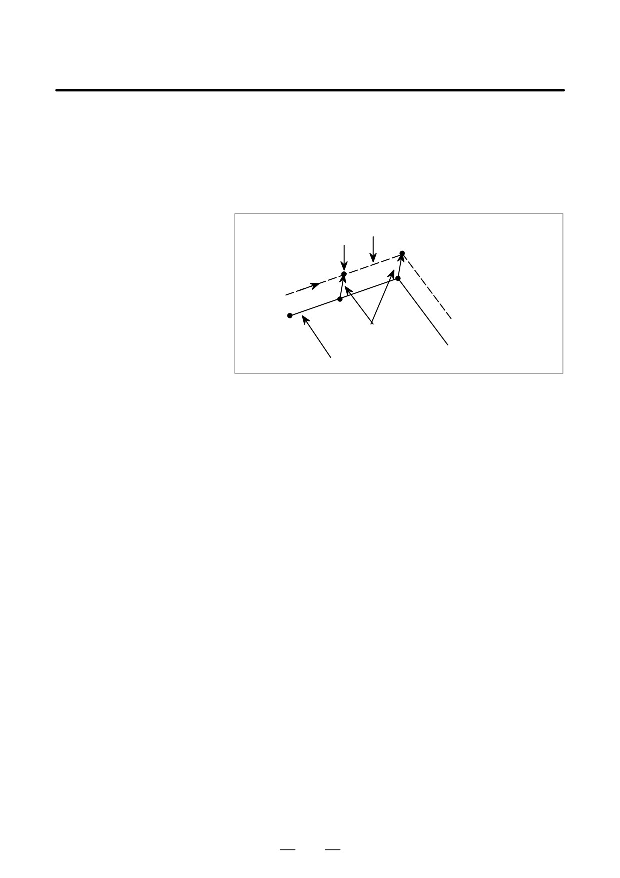
D The coordinates of point A can be read using system variables #5001
(position information
and up until the first NC statement is encountered.
values) for the interrupt
D The coordinates of point A′ can be read after an NC statement with no
program
move specifications appears.
D The machine coordinates and workpiece coordinates of point B′ can
be read using system variables #5021 and up and #5041 and up.
Tool nose center path
Interrupt generated
B
B′
A
A′
Offset vector
Programmed tool path
D Custom macro interrupt
When the interrupt signal (UINT) is input and an interrupt program is
and custom macro
called, the custom macro modal call is canceled (G67). However, when
modal call
G66 is specified in the interrupt program, the custom macro modal call
becomes valid. When control is returned from the interrupt program by
M99, the modal call is restored to the state it was in before the interrupt
was generated. When control is returned by M99Pxxxx;, the modal call
in the interrupt program remains valid.
D Custom macro interrupt
When the interrupt signal (UINT) is input while a return operation is being
and program restart
performed in the dry run mode after the search operation for program
restart, the interrupt program is called after restart operation terminates
for all axes. This means that interrupt type II is used regardless of the
parameter setting.
D DNC operation and
“Interruption type custom macro” cannot be done during DNC operation
Interruption type custom
or executing a program with an external input-output device.
macro
345
16. PROGRAMMABLE PARAMETER
ENTRY (G10)
PROGRAMMING
B-63524EN/01
PROGRAMMABLE PARAMETER ENTRY (G10)
16
General
The values of parameters can be entered in a program. This function is
used for setting pitch error compensation data when attachments are
changed or the maximum cutting feedrate or cutting time constants are
changed to meet changing machining conditions.
346

16. PROGRAMMABLE PARAMETER
B-63524EN/01
PROGRAMMING
ENTRY (G10)
Format
Format
G10L50; Parameter entry mode setting
N_R_; For parameters other than the axis type
N_P_R_; For axis type parameters
G11;
Parameter entry mode cancel
Meaning of command
N_:
Parameter No. (4digits) or compensation position No.(0 to
1023) for
pitch errors compensation +10,000 (5digit)
R_:
Parameter setting value (Leading zeros can be omitted.)
P_:
Axis No. 1 to 8 (Used for entering axis type parameters)
Explanations
D Parameter setting value
Do not use a decimal point in a value set in a parameter (R_).
(R_)
a decimal point cannot be used in a custom macro variable for R_ either.
D Axis No. (P_)
Specify an axis number (P_) from 1 to 8 (up to eight axes) for an axis type
parameter. The control axes are numbered in the order in which they are
displayed on the CNC display.
For example, specify P2 for the control axis which is displayed second.
WARNING
1
Do not fail to perform reference point return manually after
changing the pitch error compensation data or backlash
compensation data. Without this, the machine position can
deviate from the correct position.
2
The canned-cycle mode must be cancelled before entering
of parameters. When not cancelled, the drilling motion will
be activated.
NOTE
Other NC statements cannot be specified while in
parameter input mode.
347

16. PROGRAMMABLE PARAMETER
ENTRY (G10)
PROGRAMMING
B-63524EN/01
Examples
1. Set bit 2 (SPB) of bit type parameter No. 3404
G10L50 ;
Parameter entry mode
N3404 R 00000100 ;
SBP setting
G11 ;
cancel parameter entry mode
2. Change the values for the Z-axis (2nd axis) and C-axis (4th axis) in
axis type parameter No. 1322 (the coordinates of stored stroke limit
2 in the positive direction for each axis).
G10L50 ;
Parameter entry mode
N1322P2R4500 ;
Modify Z axis
N1322P4R12000 ;
Modify C axis
G11 ;
cancel parameter entry mode
348

17. MEMORY OPERATION BY
B-63524EN/01
PROGRAMMING
Series 15 TAPE FORMAT
MEMORY OPERATION BY Series 15 TAPE FORMAT
17
Programs in the Series 15 tape format can be registered in memory for
memory operation by setting bit 1 of parameter No. 0001. Registration
to memory and memory operation are possible for the functions which use
the same tape format as that for the Series 15 as well as for the following
functions which use a different tape format:
• Equal-lead threading
• Subprogram calling
• Canned cycle
• Multiple repetitive canned cycle
• Canned drilling cycle
NOTE
Registration to memory and memory operation are possible
only for the functions available in this CNC.
349
17. MEMORY OPERATION BY
Series 15 TAPE FORMAT
PROGRAMMING
B-63524EN/01
Some addresses which cannot be used for the this CNC can be used in the
17.1
Series 15 tape format. The specifiable value range for the Series 15 tape
ADDRESSES AND
format is basically the same as that for the this CNC. Sections II-17.2 to
SPECIFIABLE VALUEII-17.5 describe the addresses with a different specifiable value range.
RANGE FOR Series
If a value out of the specifiable value range is specified, an alarm is issued.
15 TAPE FORMAT
350
17. MEMORY OPERATION BY
B-63524EN/01
PROGRAMMING
Series 15 TAPE FORMAT
17.2
EQUAL-LEAD
THREADING
Format
G32IP_F_Q_;
or
G32IP_E_Q_;
I
:Combination of axis addresses
P
F :Lead along the longitudinal axis
E :Lead along the longitudinal axis
Q :Sight of the threading start angle
Explanations
D Address
Although the Series 15 allows the operator to specify the number of
threads per inch with address E, the Series 15 tape format does not.
Addresses E and F are used in the same way for specifying the lead along
the longitudinal axis. The thread lead specified with address E is therefore
also assumed as a continuous-state value for address F.
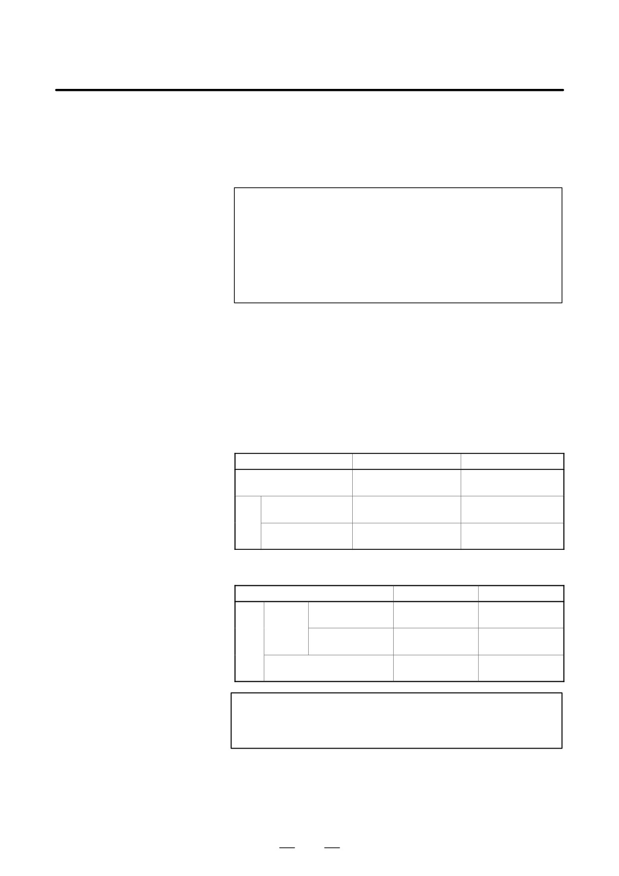
D Specifiable value range
for the thread lead
Address for thread lead
mm input
inch input
0.000001 to
E
0.0001 to 500.0000 mm
9.999999 inch
Command with a
0.000001 to
0.0001 to 500.0000 mm
decimal point
9.999999 inch
F
Command without a
0.01 to 500.00 mm
0.0001 to 9.9999 inch
decimal point
D Specifiable value range
for the feedrate
Address for feedrate
mm input
inch input
Increment
1 to 240000
0.01 to 9600.00
Feed
system (IS-B)
mm/min
inch/min
per
minute
Increment
1 to 100000
0.01 to 4800.00
F
system (IS-C)
mm/min
inch/min
0.01 to 500.00
0.0001 to 9.9999
Feed per rotation
mm/rev
inch/rev
WARNING
Specify the feedrate one more time when switching
between feed per minute and feed per rotation.
351

17. MEMORY OPERATION BY
Series 15 TAPE FORMAT
PROGRAMMING
B-63524EN/01
17.3
SUBPROGRAM
CALLING
Format
M98PffffLffff;
P:Subprogram number
L:Repetition count
Explanation
D Address
Address L cannot be used in this CNC tape format but can be used in the
Series 15 tape format.
The specifiable value range is the same as that for this CNC (1 to 9999).
D Subprogram number
If a value of more than four digits is specified, the last four digits are
assumed as the subprogram number.
D Repetition count
The repetition count L can be specified in the range from 1 to 9999. If no
repetition count is specified, 1 is assumed.
352

17. MEMORY OPERATION BY
B-63524EN/01
PROGRAMMING
Series 15 TAPE FORMAT
17.4
CANNED CYCLE
Format
Outer / inner surface turning cycle (straight cutting cycle)
G90X_Z_F_;
Outer / inner surface turning cycle (taper cutting cycle)
G90X_Z_I_F_;
I:Length of the taper section along the X-axis (radius)
Threading cycle (straight threading cycle)
G92X_Z_F_Q_;
F:Thread lead
Q:Shift of the threading start angle
Threading cycle (taper threading cycle)
G92X_Z_I_F_;
I:Length of the taper section along the X-axis (radius)
End surface turning cycle (front taper cutting cycle)
G94X_Z_F_;
End surface turning cycle (front taper cutting cycle)
G94X_Z_K_F_;
K:Length of the taper section along the Z-axis
D Address
Addresses I and K cannot be used for a canned cycle in this CNC tape
format but can be used in the Series 15 tape format.
D Specifiable value range
Same as that for equal-lead threading in section II-17.2. See section
for the feedrate
II-17.2.
353
17. MEMORY OPERATION BY
Series 15 TAPE FORMAT
PROGRAMMING
B-63524EN/01
17.5
MULTIPLE
REPETITIVE
CANNED TURNING
CYCLE
Format
Outer / inner surface turning cycle
G71P_Q_U_W_I_K_D_F_S_T_;
I
: Length and direction of cutting allowance for finishing the rough
machining cycle along the X-axis (ignored if specified)
K : Length and direction of cutting allowance for finishing the rough
machining cycle along the Z-axis (ignored if specified)
D : Depth of cut
End surface rough machining cycle
G72P_Q_U_W_I_K_D_F_S_T_;
I
: Length and direction of cutting allowance for finishing the rough
machining cycle along the X-axis (ignored if specified)
K : Length and direction of cutting allowance for finishing the rough
machining cycle along the Z-axis (ignored if specified)
D : Depth of cut
Closed-loop turning cycle
G73P_Q_U_W_I_K_D_F_S_T_;
I
: Length and direction of clearance along the X-axis (radius)
K : Length and direction of clearance along the Z-axis
D : Number of divisions
End surface cutting-off cycle
G74X_Z_I_K_F_D_;
or
G74U_W_I_K_F_D_;
I
: Distance to be traveled along the X-axis
K : Depth of cut along the Z-axis
D : Clearance of the tool at the end of the cutting path
Outer / inner surface cutting-off cycle
G75X_Z_I_K_F_D_;
or
G75U_W_I_K_F_D_;
I
: Distance to be traveled along the X-axis
K : Depth of cut along the Z-axis
D : Clearance of the tool at the end of the cutting path
Multiple repetitive threading cycle
G76X_Z_I_K_D_F_A_P_Q_;
I
: Difference of radiuses at threads
K : Height of thread crest (radius)
D : Depth of the first cut (radius)
A : Angle of the tool tip (angle of ridges)
P : Method of cutting
354
17. MEMORY OPERATION BY
B-63524EN/01
PROGRAMMING
Series 15 TAPE FORMAT
D Addresses and
If the following addresses are specified in the Series 15 tape format, they
specifiable value range
are ignored.
D I and K for the outer/inner surface rough machining cycle (G71)
D I and K for the end surface rough machining cycle (G72)
For the multiple repetitive threading cycle (G76), specify P1 (constant
depth of cutting with a single edge) or P2 (constant depth of zigzag thread
cutting with both edges) as the cutting method (P). A value of between
0 and 120 degrees can be specified for tool tip angle A. If other values
are specified, P/S alarm 062 is issued.
Address D (cutting depth and retraction distance) can be specified with
a value between -99999999 and 99999999, in the minimum input
increment, even when calculator-like decimal point input is specified
(when bit 0 (DPI) of parameter No. 3401 is set to 1). When address D
contains a decimal point, P/S alarm No. 007 is issued.
The specifiable value range for the feedrate is the same as that for
equal-lead threading. See section II-17.2.
355

17. MEMORY OPERATION BY
Series 15 TAPE FORMAT
PROGRAMMING
B-63524EN/01
17.6
CANNED DRILLING
CYCLE FORMATS
Format
Drilling cycle
G81X_C_Z_F_L_ ; or G82X_C_Z_R_F_L_ ;
R : Distance from the initial level to the R position
P : Dwell time at the bottom of the hole
F : Cutting feedrate
L : Number of repetitions
Peck drilling cycle
G81X_C_Z_R_Q_P_F_L_ ;
R : Distance from the initial level to the R position
Q: Depth of cut in each cycle
P : Dwell time at the bottom of the hole
F : Cutting feedrate
L : Number of repetitions
High-speed peck drilling cycle
G83.1X_C_Z_R_Q_P_F_L_ ;
R : Distance from the initial level to the R position
Q: Depth of cut in each cycle
P : Dwell time at the bottom of the hole
F : Cutting feedrate
L : Number of repetitions
Tapping
G84X_C_Z_R_P_F_L_ ;
R : Distance from the initial level to the R position
P : Dwell time at the bottom of the hole
F : Cutting feedrate
L : Number of repetitions
Rigid tapping
G84.2X_C_Z_R_P_F_L_S_ ;
R : Distance from the initial level to the R position
P : Dwell time at the bottom of the hole
F : Cutting feedrate
L : Number of repetitions
S : Spindle speed
Boring cycle
G85X_C_Z_R_F_L_ ; or G89X_C_Z_R_P_F_L_ ;
R : Distance from the initial level to the R position
P : Dwell time at the bottom of the hole
F : Cutting feedrate
L : Number of repetitions
Cancel
G80 ;
Explanations
D Address
For this CNC tape format, the address used to specify the number of
repetitions is K. For the Series 15 tape format, it is L.
356

17. MEMORY OPERATION BY
B-63524EN/01
PROGRAMMING
Series 15 TAPE FORMAT
D G code
Some G codes are valid only for this CNC tape format or Series 15 tape
format. Specifying an invalid G code results in P/S alarm No. 10 being
generated.
G codes valid only for the Series 15 tape format
G81, G82, G83.1, G84.2
G codes valid only for the Series 16/18/160/180
G87, G88
tape format
D Positioning plane and
For this CNC tape format, the positioning plane and drilling axis are
drilling axis
determined according to the G code for the canned cycle used.
For the Series 15 tape format, the positioning plane and drilling axis are
determined according to G17/G19.
The drilling axis is the basic axis (Z-axis or X-axis) that does not lie in
the positioning plane.
G code
Positioning plane
Drilling axis
G17
XY plane
Z-axis
G19
YZ plane
X-axis
Resetting bit 1 (FXY) of parameter No. 5101 enables fixing of the drilling
axis to the Z-axis.
D Details of data
Data for the canned cycle is specified as follows:
specifying machining
Gjj X C Z R Q P F L
;
Drilling mode
Drilling data
Number of repetitions
Hole position data
Setting
Address
Explanation
Drilling
Gjj
Canned drilling cycle G code
mode
Hole posi-
X/U (Z/W)
Incremental or absolute value used to specify the
tion data
C/H
hole position
Incremental or absolute value used to specify the
Z/W (X/U)
distance from the R position to the bottom of the
hole
Incremental value used to specify the distance
from the initial level to the R position, or absolute
R
value used to specify the R position. Which to use
depends on bit 6 of parameter No. 5102 and the G
Drilling
code system being used.
mode
Incremental value used to specify the depth of cut
Q
in each G83 or G83.1 cycle with radius program-
ming.
Dwell time at the bottom of the hole. The relation-
P
ship between the dwell time and the specified val-
ue is the same as that for G04.
F
Cutting feedrate
Number of repetitions for a sequence of cutting
Number of
L
operations. If L is not specified, it is assumed to
repetitions
be 1.
357
17. MEMORY OPERATION BY
Series 15 TAPE FORMAT
PROGRAMMING
B-63524EN/01
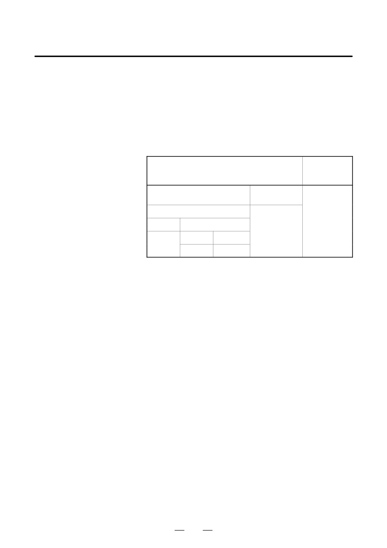
The R position is specified as an incremental value for the distance
D Specifying the R position
between the initial level to the R position. For the Series 15 tape format,
the parameter and the G code system used determine whether an
incremental or absolute value is to be used to specify the distance between
the initial level and the R position.
If bit 6 (RAB) of parameter No. 5102 is 0, an incremental value is always
used. If it is 1, the type of value used depends on the G code system used.
When G code system A is used, an absolute value is used. When G code
system B or C is used, an absolute value is used in G90 mode, and an
incremental value is used in G91 mode.
Series
Series 15 tape format
16/18/160/180
tape format
Bit 6 of parameter
Bit 6 of parameter No. 5102 = 1
No. 5102 = 0
G code system
Incremental
A
B, C
Incremental
G90
G91
Absolute
Absolute
Incremental
D Details of the canned
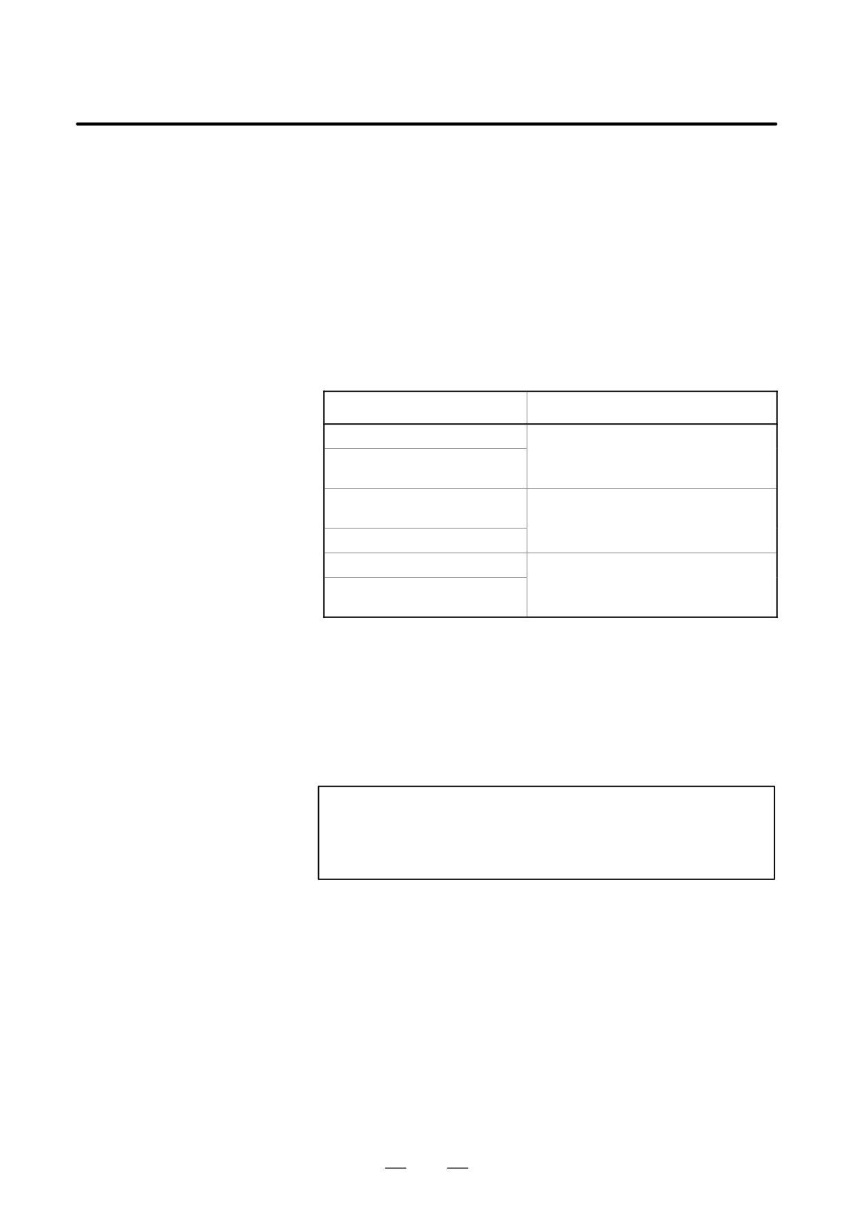
The correspondence between the G codes and this CNC tape format or
cycle
Series 15 tape format is listed below. This list also provides notes on
dwell during a canned cycle.
No. Gjj (Use) This CNC command format
1. G81 (Drilling cycle)G83 (G87) P0 <Q not specified>
No dwelling
2. G82 (Drilling cycle)G83 (G87) P <Q not specified>
The tool always dwells at the bottom of the hole.
3. G83 (Peck drilling cycle) G83 (G87) <Type B>
If the block contains a P command, the tool dwells at the bottom of the
hole.
4. G83.1 (Peck drilling cycle) G83 (G87) <Type A>
If the block contains a P command, the tool dwells at the bottom of the
hole.
Note) Either type A or B is selected according to bit 2 (RTR) of
parameter No. 5101.
5. G84 (Tapping) G84 (G88)I
f the block contains a P command, the tool dwells after it reaches the
bottom of the hole and after it is retracted to the R position.
6. G84.2 (Rigid tapping) M29 S_ G84 (G88)
If the block contains a P command, the tool dwells before the spindle
starts rotating in reverse at the bottom of the hole and before it starts
rotating in the normal direction at the R position.
7. G85 (Boring cycle) G85 (G89) P0
No dwelling
8. G89 (Boring cycle) G85 (G89) P_
The tool always dwells at the bottom of the hole.
D Clearance d for G83 and
Parameter No. 5114 determines clearance d for G83 and G83.1.
G83.1
358
17. MEMORY OPERATION BY
B-63524EN/01
PROGRAMMING
Series 15 TAPE FORMAT
D Dwell with G83 and
For Series 15-T, G83 or G83.1 does not cause the tool to dwell. For the
G83.1
Series 15 tape format, the tool dwells at the bottom of the hole only if the
block contains a P address.
D Dwelling with G84 and
In Series 15-T, G84/G84.2 causes the tool to dwell before the spindle
G84.2
starts rotating in either the normal or reverse direction, according to the
corresponding parameter setting. For the Series 15 tape format, when the
block contains a P address, the tool dwells at the bottom of the hole and
at the R position before the spindle starts rotating either in the normal or
reverse direction.
D Rigid tapping
For the Series 15 tape format, rigid tapping can be specified by using the
methods listed below:
Format
Condition (parameter), comment
G84.2 X_ Z_ R_ ...S**** ;
Setting (F10/F11) = 1
S**** ;
G84.2 X_ Z_ R_
;
M29 S**** ;
G84 X_ Z_ R_
;
* Common to Series 16 format
M29 S**** G84 X_ Z_ R_
;
G84 X_ Z_ R_
S**** ;
G84 is made a G code for rigid tapping.
Bit 0 (G84) of parameter No. 5200 = 1
S**** ;
G84 X_ Z_ R_
;
* Common to Series 16 format
D Diameter or radius
Specifying 1 for bit 7 (RDI) of parameter No. 5102 causes the canned
programming
cycle R command diameter or radius programming mode in the Series 15
tape format to match the diameter or radius programming mode for the
drilling axis.
D Disabling the Series 15
Specifying bit 3 (F16) of parameter No. 5102 disables the Series 15 tape
format
format. This applies only to the canned drilling cycle. However, the
number of repetitions must be specified by using the L address.
CAUTION
Setting bit 3 (F16) of parameter No. 5102 to 1 overrides bits
6 (RAB) and 7 (RDI) of parameter No. 5102; both settings
are assumed to be 0.
Limitations
D C-axis as the drilling
It is impossible to use the C-axis (the third axis) as a drilling axis. So,
axis
specifying G18 (ZX plane) generates P/S alarm No. 28 (plane selection
command error).
D Clamping the C-axis
For the Series 15 tape format, it is impossible to specify an M code for
clamping the C-axis.
359
18. FUNCTIONS FOR HIGH SPEED
CUTTING
PROGRAMMING
B-63524EN/01
FUNCTIONS FOR HIGH SPEED CUTTING
18
360

18. FUNCTIONS FOR HIGH SPEED
B-63524EN/01
PROGRAMMING
CUTTING
This function can convert the machining profile to a data group that can
18.1
be distributed as pulses at high-speed by the macro compiler and macro
HIGH SPEED CYCLE
executor. The function can also call and execute the data group as a
CUTTING
machining cycle using the CNC command (G05 command).
This function is applied to 1-path lathe control.
Format
G05 P10fff Lfff ;
P10fff is number of the machining cycle to be called first:
P10001 to P10999
Lfff is repetition count of the machining cycle
(L1 applies when this parameter is omitted.) :
L1 to L999
Call and execute the data for the high speed cutting cycle specified by the
macro compiler and macro executor using the above command.
Cycle data can be prepared for up to 999 cycles. Select the machining
cycle by address P. More than one cycle can be called and executed in
series using the cycle connection data in the header.
Specify the repetition count of the called machining cycle by address L.
The repetition count in the header can be specified for each cycle.
The connection of cycles and their repetition count are explained below
with an example.
Example) Assume the following:
Cycle 1 Cycle connection data 2 Repetition count 1
Cycle 2 Cycle connection data 3 Repetition count 3
Cycle 3 Cycle connection data 0 Repetition count 1
G05 P10001 L2 ;
The following cycles are executed in sequence:
Cycles 1, 2, 2, 2, 3, 1, 2, 2, 2, and3
NOTE
1
An alarm is issued if the function is executed in the G41/G42
mode.
2
Single block stop, dry run/feedrate override, automatic
acceleration/deceleration and handle interruption are
disabled during high-speed cycle machining.
361
18. FUNCTIONS FOR HIGH SPEED
CUTTING
PROGRAMMING
B-63524EN/01
Alarms
Alarm
Descriptions
number
115
The contents of the header are invalid. This alarm is issued in
the following cases.
1. The header corresponding to the number of the specified
call machining cycle was not found.
2. A cycle connection data value is not in the valid range
(0 to 999).
3. The number of data items in the header is not in the valid
range (1 to 32767).
4. The first variable No. for storing data in the executable
format is not in the valid range (#20000 to #85535).
5. The last variable No. for storing data in the executable
format exceeds the limit (#85535).
6. The first variable No. for start data in the executable
format overlaps with a variable No. used in the header.
178
High-speed cycle machining was specified in the G41/G42
mode.
179
The number of control axes specified in parameter 7510 ex-
ceeds the maximum number.
362

18. FUNCTIONS FOR HIGH SPEED
B-63524EN/01
PROGRAMMING
CUTTING
During high-speed machining, the distribution processing status is
18.2
monitored. When distribution processing terminates, P/S alarm No. 000
DISTRIBUTION
and P/S alarm No. 179 are issued upon completion of the high-speed
PROCESSING
machining command (according to the setting of ITPDL (bit 7 of
TERMINATION
parameter No. 7501)).
MONITORING
These P/S alarms can be canceled only by turning off the CNC power.
FUNCTION FOR THE
HIGH-SPEED
MACHINING
COMMAND (G05)
Explanations
D High-speed machining
High-speed machining using the high-speed remote buffer A function,
command
high-speed remote buffer B function, and high-speed cycle function
based on the G05 command
D Distribution processing
Failure to perform normal distribution processing because distribution
termination
processing required for high-speed machining exceeded the CNC
processing capacity, or because distribution data sent from the host was
delayed for some reason while the high-speed remote buffer A or G
function was being used
Number
Message
Contents
000
PLEASE TURN OFF POWER
During high-speed machining,
distribution processing was ter-
minated.
Related parameters:
Remote buffer transfer baud rate
(parameter No. 133)
179
PARAM. (NO. 7510) SETTING
Number of controlled axes in
ERROR
high-speed machining (parame-
ter No. 7150)
High-speed axis selection dur-
ing high-speed machining (bit 0
of parameter No. 7510)
363
18. FUNCTIONS FOR HIGH SPEED
CUTTING
PROGRAMMING
B-63524EN/01
This function is designed for high-speed precise machining. With this
18.3
function, the delay due to acceleration/deceleration and the delay in the
ADVANCE PREVIEW
servo system which increase as the feedrate becomes higher can be
CONTROL (G08)
suppressed.
The tool can then follow specified values accurately and errors in the
machining profile can be reduced.
This function becomes effective when advanced preview control mode is
entered.
For details, refer to the relevant manual published by the machine tool
builder.
Format
G08 P_
P1 : Turn on advanced preview control mode.
P0 : Turn off advanced preview control mode.
Explanations
D Available functions
In advanced preview control mode, the following functions are available:
(1) Linear acceleration/deceleration before interpolation
(2) Automatic corner deceleration function
(3) Feedrate cramp function by arc radins
For the function of (1) above, a special parameter for the advanced
preview control mode is provided.
D Reset
Advanced preview control mode is canceled by reset.
364

18. FUNCTIONS FOR HIGH SPEED
B-63524EN/01
PROGRAMMING
CUTTING
Notes
NOTE
1
If a block without a move command is encountered in the
advanced preview control mode, the tool decelerates and
stops in the previous block.
2
If a move block in the advanced preview control mode
contains an M, S, or T code, the tool decelerates and stops
in that block.
3
If a one-shot G code such as G04 is specified in the
advanced preview control mode, the tool decelerates and
stops in the previous block.
4
If an axial machine lock signal (MLK1 to MLK8) is set on or off
in the advanced preview control mode, acceleration/
deceleration is not carried out on the axis on which the
machine lock is performed.
5
The automatic corner override in the advanced preview
control mode can change just the internal arc cutting speed.
6
If an overtravel alarm occurs in the advanced preview
control mode, the tool decelerates and stops after the alarm
occurs. That is, the tool overruns by the deceleration
distance.
7
If the feed per revolution command is specified in the
advanced preview control mode, the spindle speed can be
changed up to 30000 min-1.
8
If a feed per minute block is followed or preceded by a feed
per revolution block in the advanced preview control mode,
the tool decelerates and stops in the previous block.
Limitations
D G08 command
Specify G08 code only in a block.
D Threading
Because this function involves automatic velocity control, the tool
decelerates in a corner, automatically changing the depth of cut, even in the
feed per minute mode. Therefore, this function cannot be used for threading.
Automatic deceleration is performed also in the feed per revolution mode.
D Functions that cannot be
In the advanced preview control mode, some functions cannot be specified.
specified in the
When specifying any of those functions, cancel the advanced preview
advanced preview
control mode in advance. After specifying the function, select the advanced
control mode
preview control mode again. The table below indicates the applicability of
the functions.
Function name
Applicability
Canned cycle for grinding
Y
Hypothetical axis interpolation
Y
8-digit program number preceded by O
f
Rapid traverse bell-shaped acceleration/deceleration
f
Dual position feedback
f
365

18. FUNCTIONS FOR HIGH SPEED
CUTTING
PROGRAMMING
B-63524EN/01
Function name
Applicability
Learning function
Y
Look-ahead repetition control
Y
Polygon between spindles
Y
Abnormal load detect function
f
Chuck/tailstock barrier
Y
PMC axis control velocity command function
Y
Corner rounding
f
Butt-type reference position setting
f
Circular threading
Y
Tandem control
f
C executor + macro executor
f
Motor velocity signal output
f
Additional C executor memory
f
Two Floppy Cassette control
f
Main CPU custom software capacity
f
Sub CPU custom software capacity
f
Straightness compensation
f
Simple spindle synchronization
f
Stroke limit check before movement
Y
Manual linear/circular interpolation
f
Three/four spindle serial outputs
f
Third/fourth spindle orientation
f
Third/fourth spindle output selection
f
Controlled axis count specification (sub side)
f
Controlled axis expansion
f
Controlled axis count specification
f
Simultaneous controlled axis expansion
f
Axis control by PMC
Y (*1)
Increment system 1/10
f
Linear acceleration/deceleration after cutting feed in-
f
terpolation
Axis removal
f
Feedrate second override
f
366

18. FUNCTIONS FOR HIGH SPEED
B-63524EN/01
PROGRAMMING
CUTTING
Function name
Applicability
Linear acceleration/deceleration before cutting feed
f
interpolation
Polar coordinate interpolation
Y
Cylindrical interpolation
Y
Polygon turning
Y
Helical interpolation
f
Tool retract & return
Y
Threading retract
Y
Continuous threading
Y
Variable-lead threading
Y
Rigid tapping
Y
Bell-shaped acceleration/deceleration after cutting
f
feed interpolation
Third/fourth reference position return
f
Floating reference position return
f
High-speed cycle cutting
Y
Axis recomposition
Y
Balance cut
Y
Single manual handle control
f
Double manual handle control
f
Handle interrupt
Y
Program restart
Y
Tool post interference check
Y
Expanded stored stroke check
Y
Stored pitch error compensation
f
External deceleration
f
Simple synchronization control
Y
Sequence number collation stop
f
Position switch
Y
Feed stop
Y
High-speed skip function
Y
Multistage skip function
Y
S serial output
f
Spindle positioning
Y
367

18. FUNCTIONS FOR HIGH SPEED
CUTTING
PROGRAMMING
B-63524EN/01
Function name
Applicability
Cs contour control
Y (*2)
First spindle orientation
f
First spindle output selection
f
Constant surface speed control
f
Actual spindle speed output
f
Spindle speed fluctuation detection
f
Spindle synchronization control
f
Multi-spindle control
f
S analog output
f
Second spindle orientation
f
Second spindle output selection
f
Direct drawing dimension programming
f
Special G code
f
Programmable data input
f
Custom macro B
f
Interrupt-type custom macro
Y
Chamfer, corner rounding
f
Inch/metric selection
f
Multiple repetitive canned cycle
f
Canned cycle for drilling
f
Play back
f
Mirror image double turret
f
F15 tape format
f
Graphic conversation
f
Pattern data input
f
Additional custom macro common variable
f
Macro executor
f
Multiple repetitive canned cycle 2
f
Coordinate system rotation
f
Workpiece coordinate system
f
Reader/punch control 1
f
Reader/punch control 2
f
External control of I/O device
f
368