FANUC Series Series 16i-TB, Series 18i-TB, Series 160i-TB, Series 180i-TB. OPERATOR’S MANUAL - page 14

18. FUNCTIONS FOR HIGH SPEED
B-63524EN/01
PROGRAMMING
CUTTING
Function name
Applicability
Remote buffer
f
High-speed remote buffer A
Y
DNC1 control
f
DNC2 control
f
External tool compensation
f
External message
f
External machine zero point shift
f
External data input
f
Angular-axis control
Y
Workpiece coordinate system preset
f
Second auxiliary function
f
B-axis control
Y
M code group check
f
Reference position shift
f
Arbitrary axis/angular-axis control
Y
Additional tool compensation A (32 items)
f
Additional tool compensation B (64 items)
f
Additional tool compensation C (99 items)
f
Tool-nose radius compensation
f
Tool geometry compensation and wear compensation
f
Automatic tool compensation
Y
Direct input of offset value measurement B
f
Y-axis offset
f
Tool life management
f
Additional tool life management (128 combinations)
f
40-m part program storage
f
80-m part program storage
f
160-m part program storage
f
320-m part program storage
f
640-m part program storage
f
1280-m part program storage
f
2560-m part program storage
f
5120-m part program storage
f
369
18. FUNCTIONS FOR HIGH SPEED
CUTTING
PROGRAMMING
B-63524EN/01
Function name
Applicability
Additional registered programs A (125 programs)
f
Additional registered programs B (200 programs)
f
Additional registered programs C (400 programs)
f
Additional registered programs D (1000 programs)
f
Additional optional block skip
f
Background editing
f
Expanded tape editing
f
Software operator’s panel
f
General switches of software operator’s panel
f
Machining time stamp
f
Japanese-language display
f
German/French-language display
f
Chinese-language display
f
Italian-language display
f
Korean-language display
f
Spanish-language display
f
Display of run time and parts count
f
Graphic display
f
Floppy Cassette directory display
f
Feed per revolution
f
Skip function (G31)
Y
Low-speed reference position return (G28)
Y
Torque limit skip
Y
Threading
Y
<Applicability>
f : The function can be used in the look-ahead control mode.
Y : The function cannot be used in the look-ahead control mode.
When using the function, cancel the look-ahead control mode.
NOTE
1
PMC axis control can be enabled only for advance feed
forward.
2
Cs contour control can be performed in the look-ahead
control mode if the G8S bit (bit 5 of parameter 1602) is set
accordingly.
370
B-63524EN/01
PROGRAMMING
19. AXIS CONTROL FUNCTION
AXIS CONTROL FUNCTION
19
371
19. AXIS CONTROL FUNCTION
PROGRAMMING
B-63524EN/01
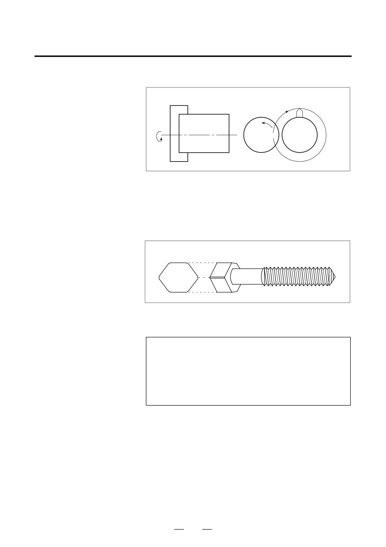
Polygonal turning means machining a polygonal figure by rotating the
19.1
workpiece and tool at a certain ratio.
POLYGONAL
TURNING
Workpiece
Workpiece
Tool
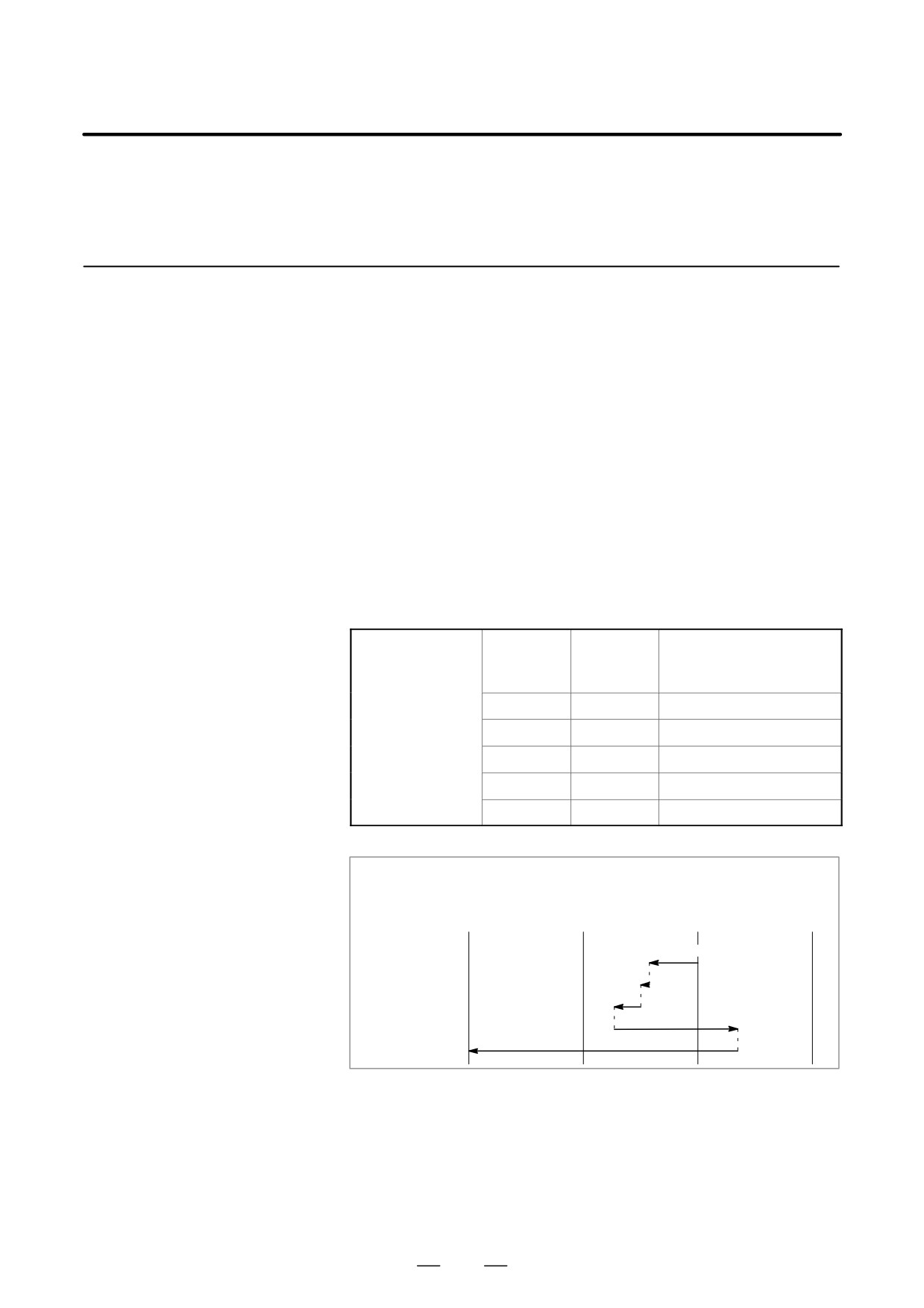
Fig. 19.1 (a) Polygonal turning
By changing conditions which are rotation ratio of workpiece and tool and
number of cutters,the machining figure can be changed to a square or
hexagon. The Machining time can be reduced as compared with
polygonal figure machining using C and X axes of the polar coordinate.
The machined figure however, is not exactly polygonal. Generally,
polygonal turning is used for the heads of square and/or hexagon bolts or
hexagon nuts.
Fig. 19.1 (b) Hexagon bolt
Format
G51.2(G251)
P_Q_;
P,Q:
Rotation ratio of spindle and Y axis
Specify range:Intefer 1 to 9 for both
P and Q
When Q is a positive value, Y axis
makes positive rotation.
When Q is a negative value, Y axis
makes negative rotation.
372
B-63524EN/01
PROGRAMMING
19. AXIS CONTROL FUNCTION
Explanations
Tool rotation for polygonal turning is controlled by CNC controlled axis.
This rotary axis of tool is called Y axis in the following description.
The Y axis is controlled by G51.2 command, so that the rotation speeds
of the workpiece mounted on the spindle (previously specified by
S-command) and the tool becomt the specified ratio.
(Example) Rotation ratio of workpiece (spindle) to Y axis is 1:2, and the
Y axis makes positive rotation.
G51.2P1Q2;
When simultaneous start is specified by G51.2, the one-rotation signal
sent from the position codes set on the spindle is detected. After this
detection. the Y axis rotation is controoled according to the rotation ratio
(P:Q) while synchronizing with the spindle speed. Namely, the Y axis
rotation is controlled so that the spindle and Y axis stand in a relation of
P:Q. This relation will be maintained until the plygonal turning cancel
command is executed (G50.2 or reset operation). The direction of Y axis
rotation is determined by the code
Q and not affected by the direction of the lposition coder rotation.
Synchronixation of the spindle and Y axis is canceled by the following
commnad:
G50.2(G250);
When G50.2 is specified, synchronization of the spindle and Y axis is
canceled and the Y axis stops.
This synchronization is also canceledd in the following casset:
i) Power off
ii) Emergency stop
iii) Servo alarm
iv) Reset (external reset signal ERS, reset/rewind ignal RRW, and RESET
key on the MDI panel)
v) Occurrence of P/S alarm Nos. 217 to 221
Example
G00X100. 0Z20.0 S1000.0M03 ; Workpiece rotation speed 1000rmp
G51.2P1 Q2 ; Tool rotation start (tool rotation speed 2000rpm)
G01X80.0 F10.0 ; X axis infeed
G04X2. ;
G00X100.0 ;X axis escape
G50.2 ; Tool rotation stop
M05 ; Spindle stop Specify G50.2 and G51.2 always in a single block.
373
19. AXIS CONTROL FUNCTION
PROGRAMMING
B-63524EN/01
D Principle of Polygonal
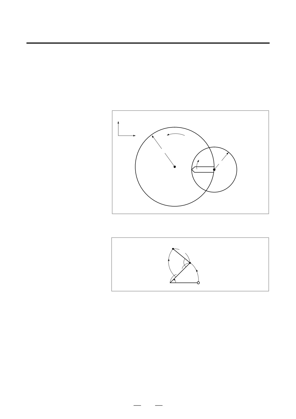
The principle of polygonal turning is explained below. In the figure below
Turning
the radius of tool and workpiece are A and B, and the angular speeds of
tool and workpiece are aand b. The origin of XY cartesian coordinates
is assumed to be the center of the workpiece.
Simplifying the explanation, consider that the tool center exists at the
position
Po (A, 0) on the workpiece periphery, and the tool nose starts from
position Pto(A-B, 0).
A ; Workpiece radius
Y
B ; Rool radius
α ; Workpiece angular speed
X
β ; Tool angular speed
Angular speedα
A
B
Pto
Tool
(0, 0)
Po
Angular
speed β
Workpiece
Po (A, 0)
Pto (A-0, 0)
In this case, the tool nose position Pt (Xt, Yt) after time t is expressed by
equation 1:
Pt (Xt, Yt)
B
P
βt
o
A
αt
Start point
(0, 0)
Xt=Acos αt-Bcos(β-α)t
(Equation 1)
Yt=Asin αt+Bsin(β-α)t
Assuming that the rotation ration of workpiece to tool is 1:2, namely,
β=2α,
equation 1 is modified as follows
Xt=Acos αt-Bcos αt=(A-B)cos αt
(Equation 2)
Xt=Asin αt+Bsin αt=(A+B)sin αt
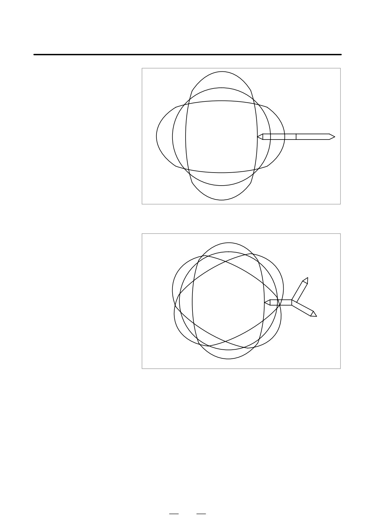
Equation 2 indicates that the tool nose path draws an ellipse with longer
diameter A+B and shorter diameter A-B.
Then consider the case when one tool is set at 180° symmetrical positions,
for atotal of two. It is seen that a square can be machined with these tools
as shown below.
374
B-63524EN/01
PROGRAMMING
19. AXIS CONTROL FUNCTION
ÇÇÇÇÇÇÇÇ
ÇÇÇÇÇÇÇÇ
ÇÇÇÇÇÇÇÇ
ÇÇÇÇÇÇÇÇ
ÇÇÇÇÇÇÇÇ
ÇÇÇÇÇÇÇÇ
ÇÇÇÇÇÇÇÇ
ÇÇÇÇÇÇÇÇ
If three tools are set at every 120°, the machining figure will be a hexagon
as shown below.
ÇÇÇÇÇ
ÇÇÇÇÇÇÇ
ÇÇÇÇÇÇÇÇÇ
ÇÇÇÇÇÇÇÇÇ
ÇÇÇÇÇÇÇÇÇ
ÇÇÇÇÇÇÇÇÇ
ÇÇÇÇÇÇÇÇÇ
ÇÇÇÇÇ
ÇÇ
375

19. AXIS CONTROL FUNCTION
PROGRAMMING
B-63524EN/01
WARNING
1
For the maximum speed of the tool, see the instruction manual supplied with the machine. Do
not specify a spindle speed higher than the maximum tool speed or a ratio to the spindle speed
that results in a speed higher than the maximum tool speed.
2
The starting point of the threading process becomes inconsistent when performed during
synchronous operation.
Cancel the synchronizing by executing G50.2 when threading.
3
The following signals become either valid or invalid in relation to the Y axis in synchronous
operation.
Valid signals in relation to Y axis:
machine lock
servo off
Invalid signals in relation to Y axis:
feed hold
interlock
ovrride
dry run
(During a dry run, however, there is no wait for a revolution signal in the G51.2 block.)
NOTE
1
The Y axis, unlike the other controlled axes, cannot be specifiied a move command as Y--.
That is, an axis move command is unnecessary for the Y axis. Because, when G51.2
(polygonal turning mode) is specified, it is only necessary to control the Y axis so that the tool
rotates at a certain ratio to the spindle rotation speed.
However, only the reference point return command (G28V0;) can be specified since the Y axis
rotation is stopped at the unstable position when G50.2 (polygonal turning mode cancel
command) is specified. If the tool rotation start position is unstable , a problem may occur, for
example, when the same figure is machined with a finishing tool after once machined with a
roughing tool.
Specification of G28V0; for Y axis is equal to the orientation command for the spindle. In the
other axes, unlike the manual reference point return, G28 usually makes reference point return
without detecting the deceleration limit. However, with G28V0; , for the Y axis, reference point
return is executed by detecting the deceleration limit, like manual reference point return.
To machine a workpiece into the same figure as the previous one, the tool and the spindle must
be in the same position as the previous time when the tool starts rotating. The tool is set start
rotation when the one-rotation signal of the position coder set on the spindle is detected.
2
The Y axis used to control tool rotation for polygonal turning uses the 4th axis. However, by
setting parameters, (No. 7610) the 3rd axis may also be used. In this case, that axis must be
named C axis.
3
Among the position display of the Y axis, the display for the machine coordinate value
(MECHINE) will change from a range of 0 to the parameter setting (the amount of movement
per revolution) as the Y axis moves.
Absolute or relative coordinate values are not renewed.
4
An absolute position detector cannot be set on the Y axis.
5
Manual continuous feed or handle feed is invalid when the Y axis is in synchronous operation.
6
The Y axis in synchronous operation is not included in the number of axis controlled
simultaneously.
376
B-63524EN/01
PROGRAMMING
19. AXIS CONTROL FUNCTION
The roll-over function prevents coordinates for the rotation axis from
19.2
overflowing. The roll-over function is enabled by setting bit 0 of
ROTARY AXIS
parameter 1008 to 1.
ROLL-OVER
19.2.1
Rotary Axis Roll-over
Explanations
For an incremental command, the tool moves the angle specified in the
command. For an absolute command, the coordinates after the tool has
moved are values set in parameter No. 1260, and rounded by the angle
corresponding to one rotation. The tool moves in the direction in which
the final coordinates are closest when bit 1 (ROAx) of parameter No. 1008
is set to 0. Displayed values for relative coordinates are also rounded by
the angle corresponding to one rotation when bit 2 (ROAx) of parameter
No. 1008 is set to 1
Examples
Assume that axis C is the rotating axis and that the amount of movement
per rotation is 360.000 (parameter No. 1260 = 360000). When the
following program is executed using the roll-over function of the rotating
axis, the axis moves as shown below.
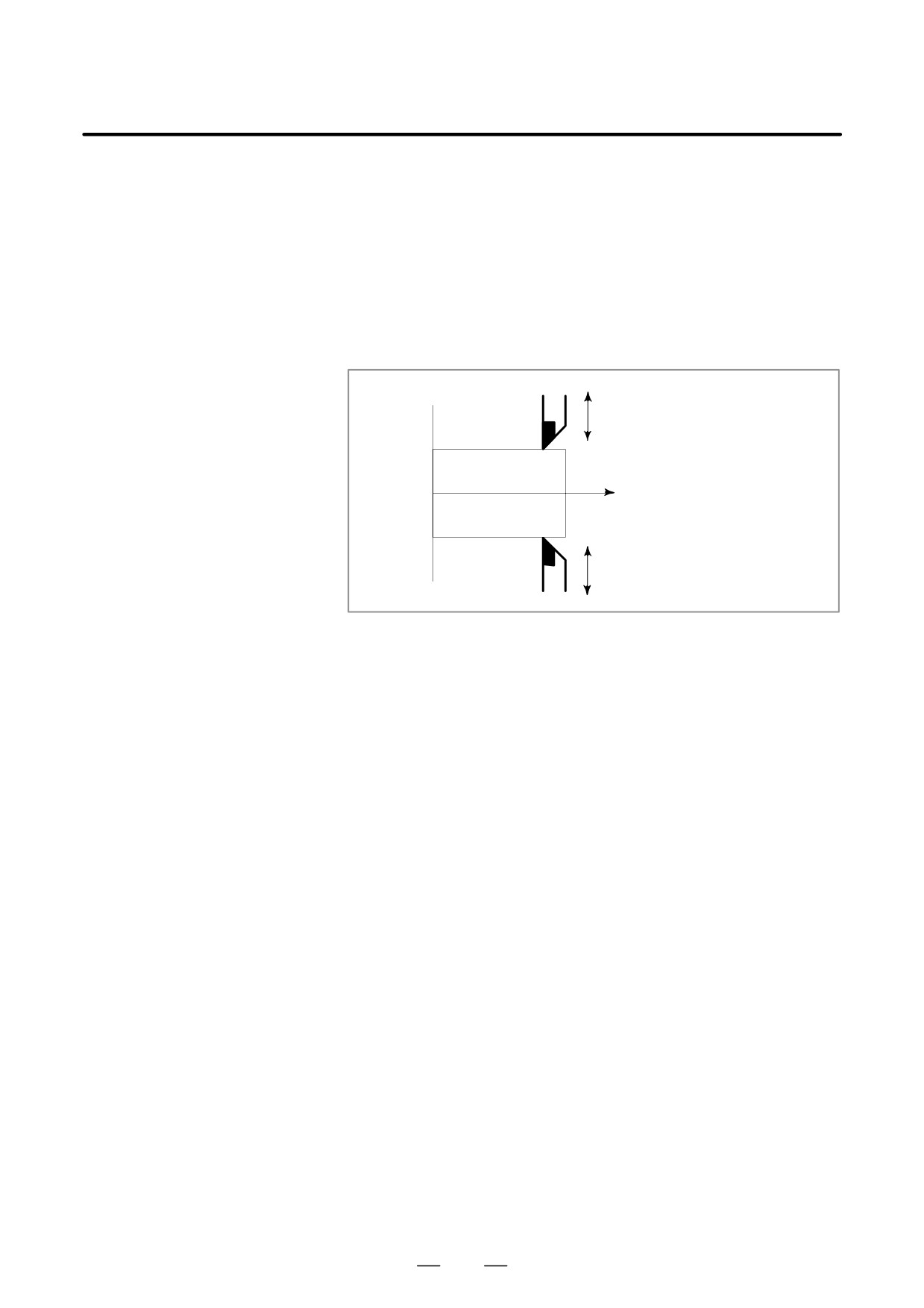
Actual
Sequence
Absolute coordinate
C0 ;
movement
number
value after movement end
value
N1 C-150.0 ;
N1
-150
210
N2 C540.0 ;
N2
-30
180
N3 C-620.0 ;
N3
-80
100
N4 H380.0 ;
N4
+380
120
N5 H-840.0 ;
N5
-840
0
Relative
-360°
-0°
360°
coordinate value-720°
Absolute
-0°
-0°
-0°
-0°
coordinate value
210°(Absolute)
N1
180°
N2
100°
N3
120°
N4
N5
377

19. AXIS CONTROL FUNCTION
PROGRAMMING
B-63524EN/01
19.2.2
This function controls a rotary axis as specified by an absolute command.
With this function, the sign of the value specified in the command is
Rotary Axis Control
interpreted as the direction of rotation, and the absolute value of the
specified value is interpreted as the coordinates of the target end position.
Explanations
This function is valid when rotary axis roll-over is enabled (ROAx bit (bit
0 of parameter 1008) is set to 1).
If the RAAx bit (bit 3 of parameter 1008) is set to 1, an absolute command
specified for the roll-over rotary axis is interpreted as follows: The sign
and absolute value of the value specified in the command represent the
direction of rotation and the end position of movement respectively.
If the RAAx bit (bit 3 of parameter 1008) is set to 0, the setting by the
RABx bit (bit 1 of parameter 1008) becomes significant.
Notes
NOTE
1
This function can be used only when the corresponding
option is provided.
2
This function is valid for a roll-over rotary axis.
3
If the RAAx bit (bit 3 of parameter 1008) is set to 1, the RABx
bit (bit 1 of parameter 1008) is ignored. To select a rotary
motion of a shorter travel distance, set both RAAx and RABx
to 0.
4
This function is not supported when the machine coordinate
system of the PMC axis control function is selected.
378
B-63524EN/01
PROGRAMMING
19. AXIS CONTROL FUNCTION
The simple synchronization control function allows synchronous and
19.3
normal operations on two specified axes to be switched, according to an
SIMPLE
input signal from the machine.
SYNCHRONIZATION
For a machine with two tool posts that can be independently driven with
CONTROL
different controlled axes, this function enables the operations described
below.
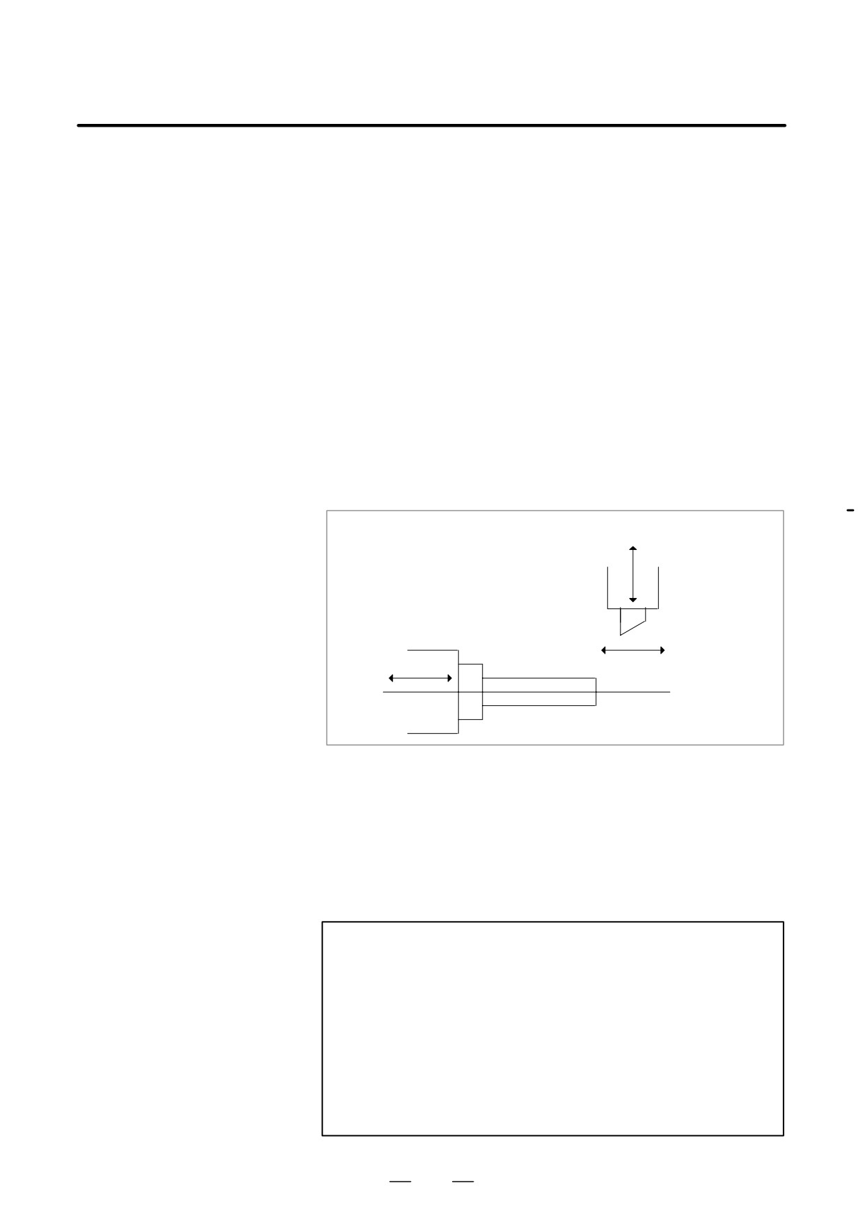
This section describes the operations of a machine having two tool posts,
both of which can be independently operated along the X-axis and
Y-axis. If your machine uses other axes for the same purpose, substitute
the corresponding axis names for X and Y.
X
Z
Y
Fig. 19.3 Sample Axis Configuration of a Machine on which
the Simple Synchronization Control Function is Executed
Explanations
Synchronous operation is possible on a machine having two tool posts.
D Synchronous operation
In synchronous operation mode, movement on one axis can be
synchronized with movement specified for another axis. The move
command can be specified for one of the two axes, which is referred to
as the master axis. The other axis, for referred synchronization with the
master axis is maintained, is referred to as the slave axis. If the master axis
is X and the slave axis is Y, synchronous operation on the X-axis (master
axis) and Y-axis
(slave axis) are performed according to Xxxxx
commands issued for the master axis.
In synchronous operation mode, a move command specified for the
master axis results in simultaneous operation of the servo motors of the
master and slave axes.
In this mode, synchronization error compensation is not performed. That
is, any positioning error between the two servo motors is not monitored,
nor is the servo motor of the slave axis adjusted to minimize any error.
No synchronization error alarm is output. Automatic operations can be
synchronized, but manual operations cannot.
D Normal operation
Normal operation is performed when different workpieces are machined
on different tables. As with normal CNC control, move commands for
the master and slave axes are specified with the addresses of those axes
(X and Y). Move commands for the two axes can be specified in an
identical block.
1
According to the Xxxxx command programmed for the master axis,
movement is performed along the X-axis, as in normal mode.
379
19. AXIS CONTROL FUNCTION
PROGRAMMING
B-63524EN/01
2
According to the Yyyyy command programmed for the slave axis,
movement is performed along the Y-axis, as in normal mode.
3
According to the Xxxxx Yyyyy command, simultaneous movements
are performed along both the X-axis and Y-axis, as in normal mode.
Both automatic and manual operations can be controlled, as in normal
CNC control.
D Switching synchronous
For details of how to switch the synchronous and normal operations, refer
and normal operations
to the manual supplied by the machine tool builder.
D Automatic reference
If a command for automatic reference position return (G28), or return to
position return
the second, third, or fourth reference position
(G30), is issued in
synchronous operation mode, a reference position return is performed for
the X-axis, and an identical movement is performed for the Y-axis. If
this Y-axis movement agrees with a return to the reference position on
the Y-axis, a lamp indicating that reference position return has been
completed for the Y-axis also lights.
It is recommended, however, that G28 and G30 be specified in normal
operation mode.
D Checking automatic
If a command for checking automatic reference position return (G27) is
reference position return
issued in synchronous operation mode, identical movements are
performed for the X-axis and Y-axis.
If these X-axis and Y-axis movements correspond to returns to the
reference positions on the X-axis and Y-axis, the lamps indicating that
reference position return has been completed for the X-axis and Y-axis
light. If not, an alarm is output.
It is recommended, however, that G27 be specified in normal operation
mode.
D Slave axis command
If a move command is specified for the slave axis in synchronous
operation mode, P/S alarm 213 is output.
D Master and slave axes
The master axis is defined in parameter 8311. The slave axis is specified
by an external signal.
Limitations
D Coordinate system
If coordinate system setting or tool compensation causing a shift in the
setting and tool
coordinate system is performed in synchronous operation mode, P/S
compensation
alarm 214 is output.
D External deceleration,
In synchronous operation mode, the signal for external deceleration,
interlock, machine lock
interlock, or machine lock of the master axis only is valid. The
corresponding slave axis signal is ignored.
D Pitch error
Pitch error compensation and backlash compensation are performed
compensation
separately for the master and slave axes.
D Manual absolute switch
In synchronous operation mode, the manual absolute switch must be set
to on (ABS must be set to 1). If the switch is set to off, the correct slave
axis movement may not be made.
D Manual operation
Manual operations cannot be synchronized.
380
B-63524EN/01
PROGRAMMING
19. AXIS CONTROL FUNCTION
The synchronization control function enables the synchronization of
19.4
movements on two axes. If a move command is programmed for one of
SYNCHRONIZATION
those two axes (master axis), the function automatically issues the same
CONTROL
command to the other axis (slave axis), thus establishing synchronization
between the two axes. The parking state can be selected to suppress
movement of the slave axis, even if a move command is specified for the
master axis. If the parking state is used with the synchronization control
function, the operation can be controlled as follows:
1
Synchronizes the movement on the slave axis with that of the master
axis.
2
Performs slave axis movement according to the move command
programmed for the master axis. However, the movement specified
by the command is not made for the master axis itself (master parking).
3
Updates the slave axis coordinates according to the distance travelled
along the master axis. However, no movement is made for the slave
axis (slave parking).
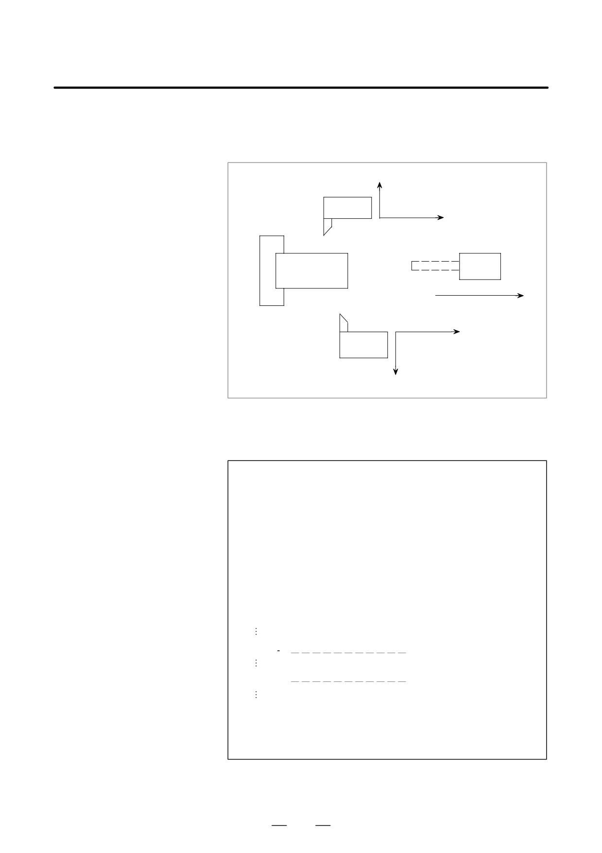
When method 2 above is used, the following operation can be performed:
(Example) Synchronizing movements on the Z-axis and Y-axis
(master parking)
X
Z
Y
Movement is performed for the X-axis and Y-axis according to
commands issued for the X-axis and Z-axis. (The Y-axis movement is
synchronized with that of the Z-axis.) If the Z-axis is set to the parking
state, the coordinates on the Z-axis and Y-axis are updated.
As the coordinates on the Z-axis and Y-axis are always updated, the
coordinate system need not be reset when the synchronization status is
changed. A move command can be executed immediately after the status
is changed.
NOTE
1
In the synchronization control described above, an identical
move command is simultaneously output for two servo
processing systems. Positional error between the two servo
motors is not monitored, nor is either servo motor adjusted
to minimize the error. That is, synchronization error
compensation is not carried out.
2
The method used to specify the synchronization control
function varies with the machine tool builder. For details,
refer to the manual supplied by the machine tool builder.
381
19. AXIS CONTROL FUNCTION
PROGRAMMING
B-63524EN/01
This function sets an axis (B-axis) independent of the basic controlled
19.5
axes X1, Z1, X2, and Z2 and allows drilling, boring, or other machining
B-AXIS CONTROL
along the B-axis, in parallel with the operations for the basic controlled
(G100, G101, G102,
axes. The X2 and Z2 axes can be used in two-path control mode.
G103, G110)
X1
First
tool post
Z1
Third
Workpiece
tool post
B
Z2
Second
tool post
X2
Format
D Registering operation
programs
G101-G100
: Starts registering the first program.
G102-G100
: Starts registering the second program.
G103-G100
: Starts registering the third program.
G100
: Ends registering of the programs.
Three operations (programs) on the B-axis can be registered. (In two-
path control mode, three programs can be registered for each tool post.)
The B-axis operation program must be specified in the blocks between
G101, G102, or G103 and G100, allowing it to be discriminated from the
normal NC program.
The registered operation is started upon executing the corresponding M
code, described below.
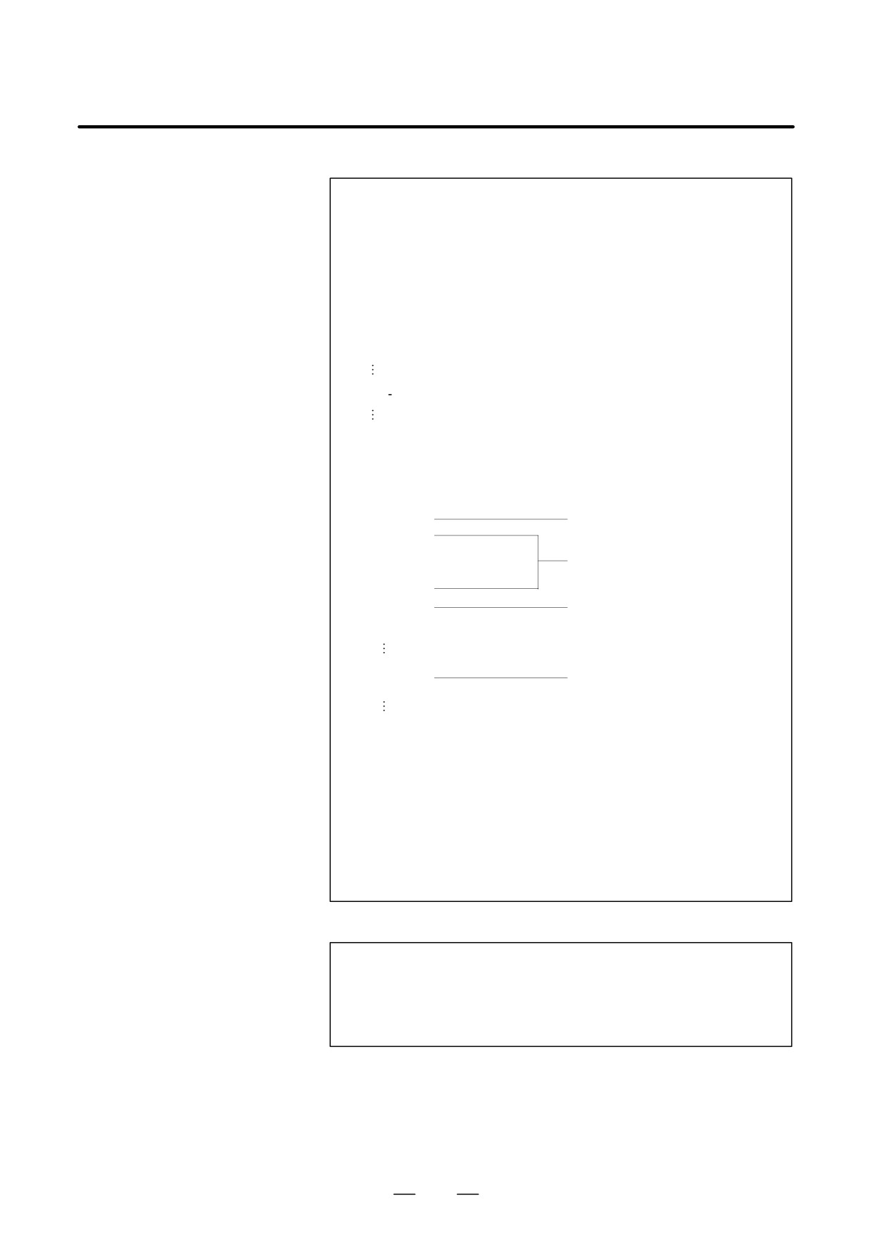
O1234 ;
Normal NC program
G101 ;
Starts registering of a B-axis
operation program.
B-axis operation program
G100 ;
Ends registering of the B-axis
operation program.
Normal NC program
M30 ;
Note) In the block of G101, G102, G103, or G100, specify no other codes.
382
B-63524EN/01
PROGRAMMING
19. AXIS CONTROL FUNCTION
D Command used to start
the operation
To start an operation, the miscellaneous functions (M**) specified in
parameters 8251 to 8253 are used.
Parameter 8251:
M code used to start operation of the first program
Parameter 8252:
M code used to start operation of the second program
Parameter 8253:
M code used to start operation of the third program
O1234 ;
Starts executing the registered B-axis operation. In
M** ;
subsequent blocks, the normal NC program and the
B-axis operation program are executed in parallel.
(** is specified in parameters 8251 to 8253.)
M30 ;
Example
01234 ;
G50 X100. Z200. ;
G101 ;
Starts registering of an
G00 B10. ;
operation program.
M03 ;
G04 P2500 ;
Blocks of the B-axis
G81 B20. R15. F500 ;
operation program
G28 ;
G100 ;
Ends registering of the
G00 X80. Z50. ;
operation program.
G01 X45. F1000 ;
G00 X10. ;
M** ;
Command used to start the
G01 Z30. F300 ;
programmed operation
M30 ;
to
:
Specify the B-axis operation program in blocks between
G101, G102, or G103 and G100. The program is registered
in program memory.
: Starts executing the B-axis operation registered with to above.
In subsequent blocks, the normal NC operation and the B-axis
operation are executed in parallel. An M code of the miscellaneous
function is used to start the B-axis operation. The M code, used to
start the operation, is specified in parameters 8251 to 8253.
D Single-motion operation
G110 [operation command];
A single-motion operation for the B-axis can be specified and
executed as shown above. Such an operation need not be regis-
tered as a special (first to third) program. Nor does it need to be
by a special command, as described above.
383

19. AXIS CONTROL FUNCTION
PROGRAMMING
B-63524EN/01
Explanations
D Specifying two-path
One of the following three two-path control modes can be selected:
control mode
1
B-axis control is executed for either tool post 1 or 2.
2
B-axis control is executed separately for tool posts 1 and 2.
3
Identical B-axis control is executed for tool posts 1 and 2.
The mode is selected according to the value specified for parameter 8250
for each tool post.
D Codes that can be used
The following 13 G codes, and the M, S, and T codes of the miscellaneous
in a B-axis operation
functions, can be used in a B-axis operation program:
program
Code
Description
G00
Positioning (rapid traverse)
G01
Linear interpolation (cutting feed)
G04
Dwell
G28
Reference position return, automatic coordinate system setting
G80
Canned cycle, cancel
G81
Drilling cycle, spot drilling
G82
Drilling cycle, counterboring
G83
Peck drilling cycle
G84
Tapping cycle
G85
Boring cycle
G86
Boring cycle
G98
Feed per minute
G99
Feed per rotation
M**
Auxiliary function
S**
Auxiliary function
T**
Auxiliary function, tool offset
G28 (reference position return)
Unlike the normal G28 cycle, the G28 cycle for a B-axis operation does
not include intermediate point processing. For example, the following
cannot be specified:
G28 B99.9;
G80 to G86 (canned drilling cycle)
Of the canned drilling cycles supported by the FANUC Series 16 or Series
18 for machining centers, those cycles equivalent to G80 to G86 can be
executed.
Data can be specified in the same way as for the FANUC Series 16 or
Series 18 for machining centers, except for the following points:
1. The drilling position is not specified with X and Y.
2. The distance from point R to the bottom of the hole is specified with
B.
384
B-63524EN/01
PROGRAMMING
19. AXIS CONTROL FUNCTION
3. All operations are executed in the initial level return mode.
4. The repetition count (K) cannot be specified.
5. In canned cycle mode, point R must be specified.
(If point R is
omitted, P/S alarm No. 5036 is output.)
6. The drilling start point (d) for the G83 (peck drilling) cycle is specified
with parameter 8258.
G98, G99 (feed per minute, feed per rotation)
The MDF bit
(bit
2 of parameter
8241) specifies an initial
continuous-state G code for G110, or the G code to start registration of
the operation program (G101, G102, G103).
When the MDF bit is set to 0, the initial continuous-state code is G98.
When the MDF bit is set to 1, the initial continuous-state code is G99.
Example)
When MDF is set to 0
G110 B100. F1000. ; 1000 mm/min
G110 G99 B100. F1 ; 1 mm/rev
NOTE
In two-path control mode, the system uses the actual
spindle speed, calculated from the feedback signal output
by the position coder connected to the tool post to which the
controlled axis belongs.
M, S, and T codes (auxiliary functions)
According to a numeric value subsequent to address M, S, or T, the binary
code and strobe signal are sent to the machine. The codes and signals for
addresses M, S, and T are all output to an identical interface and can be
used to control power-on or power-off of the machine. For this purpose,
the axis control interface of the PMC is used, which differs from that used
for the miscellaneous functions for the normal NC program. The
following M codes, used to control the spindle, are automatically output
during the G84 (tapping) or G86 (boring) cycle:
M03: Forward spindle rotation
M04: Reverse spindle rotation
M05: Spindle stop
T** to T (** + 9), where ** is the number specified in parameter 8257,
are used as the codes of the auxiliary functions to adjust the tool offset.
Example)
T50 to T59 if parameter 8257 is set to 50
1. An M, S, or T code must not be specified in a block containing
another move command. The M, S, and T codes must not be
specified in an identical block.
2. Usually, normal NC operation and B-axis operation are
independent of each other. Synchronization between operations
can be established by coordinating the miscellaneous functions of
the normal NC program and B-axis operation program.
385
19. AXIS CONTROL FUNCTION
PROGRAMMING
B-63524EN/01
(Normal NC operation)
(Registered B-axis operation)
:
:
M11 ; G00 B111 ;
G01 X999 : G01 B222 ;
G28 Z777 ; G28 ;
M50 ; M50 ;
G00 X666 ; G81 B444 R111 F222 ;
:
:
Upon receiving M50 of both the normal NC program and the B-axis
program, the PMC ladder outputs the completion signals (FIN) for the
two miscellaneous functions. G00 X666 of the normal NC program and
G81 B444 R111 F222 of the B-axis program are executed
simultaneously.
Custom macro
Custom macro variables (local variables, common variables, system
variables #****) can be used in an operation program between G101,
G102, or G103 and G100.
1. The value of the macro variable is calculated not from the data existing
upon execution of the B-axis operation, but from the data existing at
registration of the operation program.
2. An instruction that causes a branch to a location beyond the range of
G101, G102, or G103 to G100 is processed without being checked.
3. In the two-path control mode, tool posts 1 and 2 use different macro
variables.
D Operation program
When a new operation program is registered, the previous operation
program is automatically deleted.
If an error is detected in an operation program to be registered, the
program is initialized but is not registered.
D Modal
In the same way as a normal NC program, the B-axis operation program
can use the following as modal data: modal G codes, F codes, and P, Q,
and F codes in the canned cycle. These codes do not affect the modal
information of the normal NC program. When a B-axis operation
program is started (by G101, G102, or G103), the initial modal data is set
for the program. It is not affected by the previous modal information.
Example)
:
G01 X10. F1000 ;
G101 (G102, G103) ;
B10. ;
G01 B-10. F500 ;
G100 ;
X-10. ;
:
Irrespective of the modal information for normal operation
(G01
specified in block), block
specifies G00 if the MDG bit (bit 1 of
parameter 8241) is set to 0, or G01 if the MDG bit is set to 1.
Block causes movement with F1000, specified in block 1.
386
B-63524EN/01
PROGRAMMING
19. AXIS CONTROL FUNCTION
D Operation start
The MST bit (bit 7 of parameter 8240) specifies the method used to start
command
the B-axis operation as described below:
If the MST bit is set to 1, the B-axis operation is started when the M code
to start the operation is executed.
If the MST bit is set to 0, the B-axis operation is started when the M code
used to start the operation is executed and the PMC outputs the
miscellaneous function completion signal (FIN).
Up to five M codes for starting the programs can be stored. The programs
corresponding to these M codes are executed in succession. (In two-path
control mode, up to five codes can be stored for each tool post.)
Example)
When the first, second, and third programs are started by M40, M41,
and M42, respectively
O1234. ;
:
:
M40 ; M code for starting the first program
M41 ; M code for starting the second program
M42 ; M code for starting the third program
M40 ; M code for starting the first program
M41 ; M code for starting the second program
:
:
M30 ;
As M41 is specified while the program started by M40 is being executed,
the second program is automatically started upon termination of the first
program.
M42, M40, and M41, specified during execution of the first program, are
stored such that the corresponding programs are executed in the same
order as that in which the M codes are specified.
If six or more M codes for starting the programs are specified while a
program is being executed, P/S alarm 5038 is output.
In two-path control mode, the M code specified for tool post 1 starts the
B-axis program registered for tool post 1. The M code specified for tool
post 2 starts the B-axis program registered for tool post 2.
D Specifying absolute or
The amount of travel along the B-axis can be specified in either absolute
incremental mode
or incremental mode. In absolute mode, the end point of travel along the
B-axis is programmed. In incremental mode, the amount of travel along
the B-axis is programmed directly.
The ABS bit (bit 6 of parameter 8240) is used to set absolute or
incremental mode. When the ABS bit is set to 1, absolute mode is
selected. When the ABS bit is set to 0, incremental mode is selected. The
mode is specified with this parameter when the program is registered.
387
19. AXIS CONTROL FUNCTION
PROGRAMMING
B-63524EN/01
The T**; command shifts the end point of the specified B-axis travel, in
D Specifying a tool offset
either the positive or negative direction, by the amount specified with the
B-axis offset screen. If this function is used to set the difference between
the programmed tool position and actual tool position in machining, the
program need not be modified to correct the tool position.
The value specified with parameter 8257 is assigned to the auxiliary
function to cancel the offset. The subsequent nine numbers are assigned
to the tool offset functions. These auxiliary function numbers are
displayed on the B-axis offset screen. For details, see “OPERATION.”
If a G110 block is specified, a single-motion operation along the B-axis
D Single-motion operation
can be specified and executed. In single-motion operation mode, a single
block results in a single operation. The single-motion operation is
executed immediately provided if it is specified before the B-axis
operation is started. If the operation is specified while a registered
program is being executed, the operation is executed once that program
has terminated.
After the specified single-motion operation has been executed, the next
block is executed.
:
G110 G01 B100. F200 ; Block for single-motion
operation along B-axis
G00 X100. Z20. ;
:
D Program memory
An operation program is registered in program memory as a series of
different blocks of the move, dwell, auxiliary, and other functions.
Program memory can hold a desired number of blocks, up to a maximum
of 65535 blocks for each program. If the program memory contains no
free space when an attempt is made to register a B-axis program, P/S
alarm 5033 is output. Six blocks require 80 characters of program
memory. A canned cycle (G81 to G86) is also registered as a series of
blocks, such as travel and dwell.
The entire program memory is backed up by battery. The programs
registered in program memory are thus retained even after the system
power is turned off. After turning the system power on, the operation can
be started simply by specifying the M code for starting the program.
Example)
:
G101 ;
G00 B10. ;
One block
G04 P1500 ;
One block
G81 B20. R50. F600 ;
Three blocks
G28 ;
One block
M15 ;
One block
G100 ;
:
(Total 7 blocks)
D Reset
When the NC is reset by pressing the MDI reset key or by the issue of an
external reset signal, reset and rewind signal, or emergency stop, B-axis
control is also reset. The PMC interface signal can reset only B-axis
control. For details, refer to the manual supplied by the machine tool
manufacturer.
388
B-63524EN/01
PROGRAMMING
19. AXIS CONTROL FUNCTION
A B-axis operation can be executed only when the B-axis can be
D PMC-controlled axis
controlled by the PMC. For details, refer to the manual supplied by the
machine tool builder.
Limitations
D Single-motion operation
1.
Only a single-motion operation can be specified with G110.
G110 G00 B100. ;
OK
G110 G28 ;
OK
G110 G81 B100. R150.0 F100 ; . . . P/S alarm No. 5034
2.
A canned cycle (G81 to G86), and other operations containing
multiple motions, cannot be specified with G110.
If an inhibited operation is specified, P/S alarm No. 5034 is output.
3.
modal information specified with G110 does not affect the subsequent
blocks. In the G110 block, the initial modal value specified at the start
of the operation becomes valid, irrespective of the modal information
specified the previous blocks.
Example)
When the MDG bit (bit 1 of parameter 8241) is set to 1 and the
MDF bit (bit 2 of parameter 8241) is set to 1
G98 G00 X100. F1000 ;
(1)
G110 B200. F2 ;
(2)
X200. ;
(3)
G01 X200. ;
(4)
Block (2) instigates cutting feed (G01) at 2.0 mm/rev (G99).
Block (3) instigates rapid traverse (G00).
Block (4) instigates cutting feed (G01) at 1000 mm/min (G98).
4.
During tool-tip radius compensation, two or more G110 blocks cannot
be specified in succession. If such blocks are specified in succession,
P/S alarm No. 504 is output. To specify two or more G110 blocks in
succession for a B-axis operation, register the blocks as a program
with G101, G102, or G103 and G100.
389
19. AXIS CONTROL FUNCTION
PROGRAMMING
B-63524EN/01
Examples
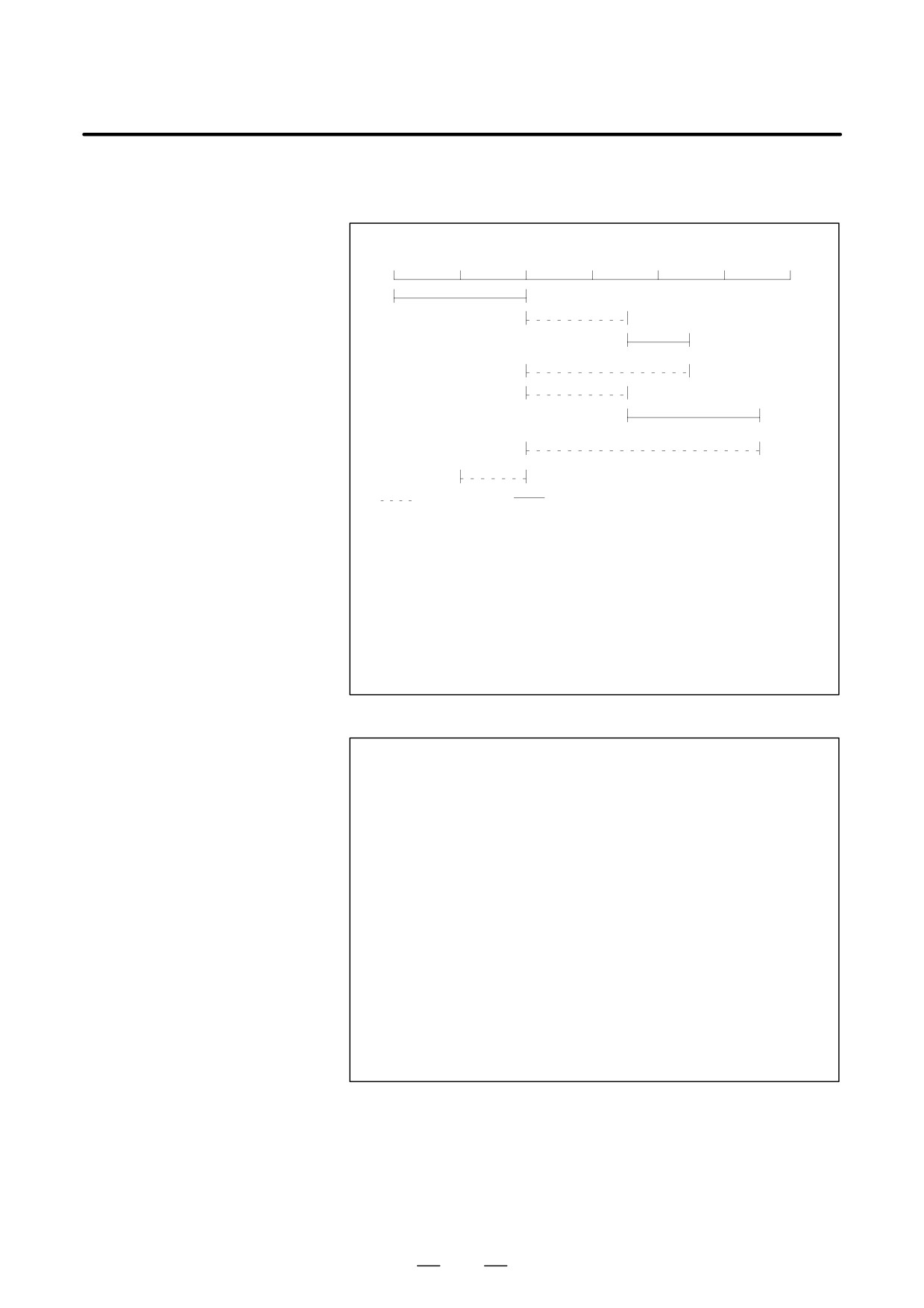
D Absolute or incremental
mode
Absolute or incremental mode
0
100
200
300
400
500
600
(1)
(200)
(2)
(350)
(450)
⋅ Dwell
(200)
(3)
(350)
(550)
⋅ Dwell
(200)
(100)
(
Rapid traverse
Cutting feed
⋅Dwell
(***) Absolute value
)
Incremental mode
Absolute mode
G101 (G012, 103) ;
G101 (G012, G103) ;
(1) G01 B200. F100 ;
(1) G01 B200. F100 ;
(2) G82 B100. R150. P5000 F200 ;
(2) G82 B450. R350. P5000 F200 ;
(3)
B200. R150. P5000 ;
(3)
B550. R350. P5000 ;
(4) G00 B-100. ;
(4) G00 B100. ;
G100 ;
G100 ;
:
:
M**
M**
:
:
M30 ;
M30 ;
D Tool posts 1 and 2
If a single axis is used as the common B-axis of the two tool posts in
two-path control, tool posts 1 and 2 share the B coordinate.
For example, after program 1 for tool post 1 and program 2 for tool post
2 are executed in that order, the total travel along the B-axis appears to
be +100.
<Program 1>
G101 ;
:
G00 B200. ; (Absolute mode)
G100 ;
:
M30 ;
<Program 2>
G101 ;
G00 B300. ; (Absolute mode)
:
G100 ;
:
M30 ;
390
B-63524EN/01
PROGRAMMING
19. AXIS CONTROL FUNCTION
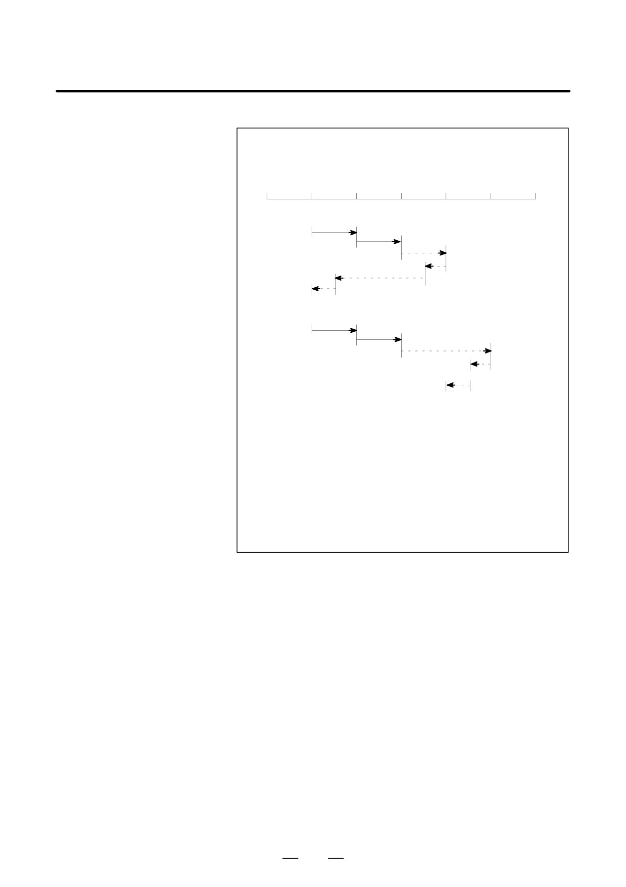
D Tool offset
Example)
When parameter 8257 is set to 50
Auxiliary function used to cancel the offset: T50
Auxiliary functions used to adjust a tool offset: T51 to T59
-10
0
10
20
30
40
50
(350)
(Absolute mode)
(10)
(1)
(20)
(2)
(30)
(3)
(4)
(25)
(5)
(5)
(6)
(0)
(Incremental mode)
(10)
(1)
(20)
(2)
(40)
(3)
(4)
(35)
(5)
(35)
⋅
(6)
(30)
Program
G101 (G012, G103) ;
(1) G01 B10. F100 ;
(2) T51 ;
(3) G00 B20. ;
(4) T52 ;
(5) B0. ;
(6) T50 ;
G100 ;
:
M**;
Where the offset of T51 is 10.0 and the offset
:
of T52 is 5.0
391
19. AXIS CONTROL FUNCTION
PROGRAMMING
B-63524EN/01
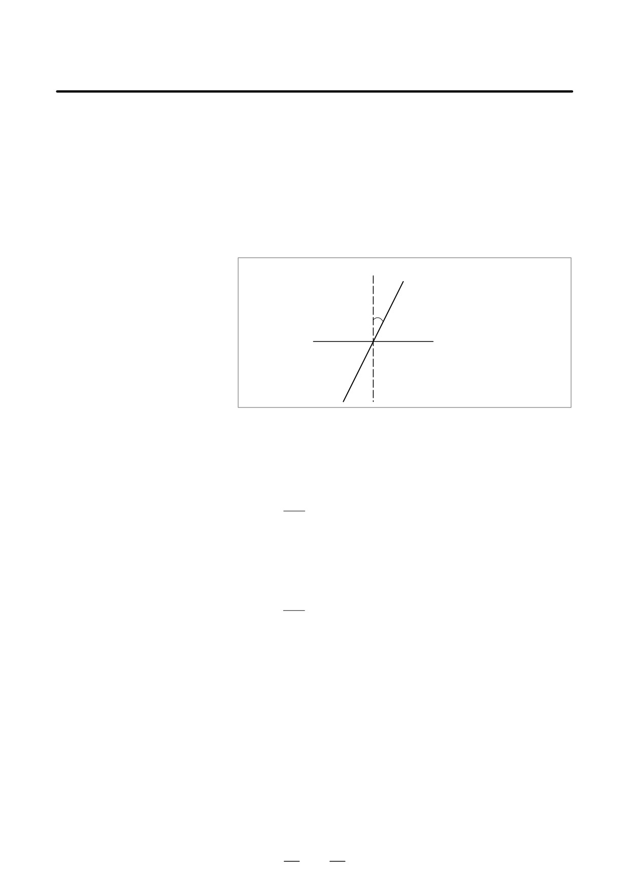
When the angular axis makes an angle other than
90° with the
19.6
perpendicular axis, the angular axis control function controls the distance
ANGULAR AXIS
traveled along each axis according to the inclination angle. For the
CONTROL /
ordinary angular axis control function, the X-axis is always used as the
ARBITRARY
angular axis and the Z-axis is always used as the perpendicular axis. For
angular axis control B, however, arbitrary axes can be specified as the
ANGULAR AXIS
angular and perpendicular axes, by specifying parameters accordingly.
CONTROL
A program, when created, assumes that the angular axis and perpendicular
axis intersect at right angles. However, the actual distance traveled is
controlled according to an inclination angle.
+X
Program coordinate system
+X
Coordinate system actually used
(angular axis)
θ
+Z (perpendicular axis)
θ : Inclination angle
Explanations
When the angular axis is the X-axis and the perpendicular axis is the
Z-axis, the amount of travel along each axis is controlled according to the
formulas shown below.
The distance to be traveled along the X-axis is determined by the
following formula :
Xp
Xa +
cos q
The distance traveled along the Z-axis is corrected by the inclination of
the X-axis, and is determined by the following formula:
Za + Zp-1
2Xptanq
The speed component along the X-axis of feed rate is determined by the
following formula:
Fp
Fa +
cos q
Xa, Za, Fa:Actual distance and speed
Xp, Zp, Fp:Programmed distance and speed
D Method of use
The angular and perpendicular axes to which angular axis control is to be
applied must be specified beforehand, using parameters (No. 8211 and
8212).
Parameter AAC (No. 8200#0) enables or disables the inclined axis
control function. If the function is enabled, the distance traveled along
each axis is controlled according to an inclination angle (No. 8210).
Parameter AZR (No. 8200#2) enables angular axis manual reference
point return only with a distance along the angular axis.
If perpendicular/angular axis control disable signal NOZAGC has been
set to 1, the angular axis control function is enabled only for the angular
axis. In such a case, the move command for the angular axis is converted
to angular coordinates. The perpendicular axis is not affected by the move
command for the angular axis.
392

B-63524EN/01
PROGRAMMING
19. AXIS CONTROL FUNCTION
D Absolute and relative
An absolute and a relative position are indicated in the programmed
position display
Cartesian coordinate system. Machine position display
D Machine position display
A machine position indication is provided in the machine coordinate
system where an actual movement is taking place according to an
inclination angle. However, when inch/metric conversion is performed,
a position is indicated which incorporates inch/metric conversion applied
to the results of inclination angle operation.
WARNING
1
After inclined axis control parameter setting, be sure to
perform manual reference point return operation.
2
If bit 2 (AZR) of parameter No. 8200 has been set to 0, such
that manual reference position return along the angular axis
also causes movement along the perpendicular axis, once
manual reference position return has been performed along
the angular axis, also perform manual reference position
return along the perpendicular axis.
3
Once the tool has been moved along the angular axis with
perpendicular/angular axis control disable signal NOZAGC
set to
1, manual reference position return must be
performed.
4
Before attempting to manually move the tool along both the
angular and perpendicular axes simultaneously, set
perpendicular/angular axis control disable signal NOZAGC
to 1.
NOTE
1
If an inclination angle close to 0° or "90° is set, an error can
occur. A range from "20° to "60° should be used.
2
Before a perpendicular axis reference point return check
(G37) can be made, angular axis reference point return
operation must be completed.
3
For arbitrary angular axis control, if the same axis number
has been specified in both parameters No. 8211 and 8212,
or if a value outside the valid data range has been specified
for either parameter, the angular and perpendicular axes
will be as follows:
Angular axis: First axis
Perpendicular axis: Second axis
393
19. AXIS CONTROL FUNCTION
PROGRAMMING
B-63524EN/01
To replace the tool damaged during machining or to check the status of
19.7
machining, the tool can be withdrawn from a workpiece. The tool can
TOOL WITHDRAWAL
then be advanced again to restart machining efficiently.
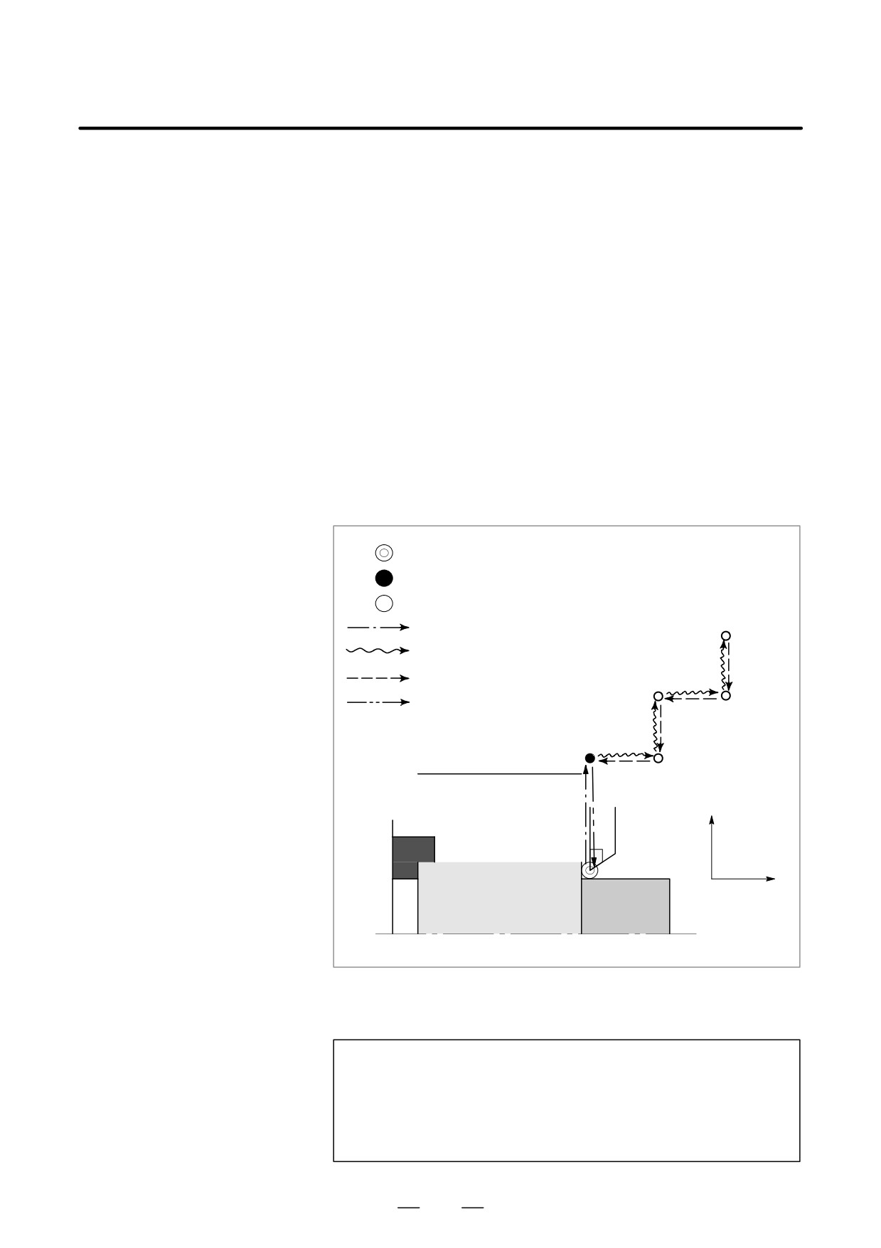
AND RETURN (G10.6)The tool withdrawal and return operation consists of the following four
steps:
D Retract
The tool is retracted to a predefined position using the TOOL WITHDRAW
switch.
D Withdrawal
The tool is moved to the tool-change position manually.
D Return
The tool returns to the retract position.
D Repositioning
The tool returns to the interrupted position.
For the tool withdrawal and return operations, see Section
4.8 in
“Operation.”
: Position where the TOOL WITHDRAW switch was turned on
: Programmed position
: Position to which the tool is retracted by manual operation
: Retraction path
: Manual operation (withdraw path)
: Return path
: Repositioning
X
Z
Format
Specify a retraction axis and distance in the following format:
G10.6 IP_ ;
IP_ : In incremental mode, retraction distance from the position
where the retract signal is turned on
In the absolute mode, retraction distance to an absolute
position
394
B-63524EN/01
PROGRAMMING
19. AXIS CONTROL FUNCTION
Explanations
D Retraction
When the TOOL WITHDRAW switch on the machine operator’s panel
is turned on during automatic operation or in the automatic operation stop
or hold state, the tool is retracted the length of the programmed retraction
distance. This operation is called retraction. The position at which
retraction is completed is called the retraction position. Upon completion
of retraction, the RETRACT POSITION LED on the machine operator’s
panel goes on.
When the TOOL WITHDRAW switch is turned on during execution of
a block in automatic operation, execution of the block is interrupted
immediately and the tool is retracted. After retraction is completed, the
system enters the automatic operation hold state.
If the retraction distance and direction are not programmed, retraction is
not performed. In this state, the tool can be withdrawn and returned.
When the TOOL WITHDRAW switch is turned on in the automatic
operation stop or hold state, the tool is retracted, then the automatic
operation stop or hold state is entered again.
When the TOOL WITHDRAW switch is turned on, the tool withdraw
mode is set. When the tool withdraw mode is set, the TOOL BEING
WITHDRAWN LED on the machine operator’s panel goes on.
D Withdrawal
When the manual mode is set, the tool can be moved manually (manual
continuous feed or manual handle feed) to replace the tool or measure a
machined workpiece. This operation is called a withdrawal. The tool
withdrawal path is automatically memorized by the CNC.
D Return
When the mode is returned to automatic operation mode and the TOOL
RETURN switch on the machine operator’s panel is turned off, the CNC
automatically moves the tool to the retraction position by tracing the
manually-moved tool path backwards. This operation is called a return.
Upon completion of a return to the retraction position, the
RETRACTIONS POSITION LED comes on.
D Repositioning
When the cycle start button is pressed while the tool is in the retraction
position, the tool moves to the position where the TOOL WITHDRAW
switch was turned on. This operation is called repositioning. Upon
completion of repositioning, the TOOL BEING WITHDRAWN LED is
turned off, indicating that the tool withdrawal mode has terminated.
Operation after completion of repositioning depends on the automatic
operation state when the tool withdrawal mode is set.
(1) When the tool withdrawal mode is set during automatic operation,
operation is resumed after completion of repositioning.
(2) When the tool withdrawal mode is set when automatic operation is
held or stopped, the original automatic operation hold or stop state is
set after completion of repositioning. When the cycle start button is
pressed again, automatic operation is resumed.
395
19. AXIS CONTROL FUNCTION
PROGRAMMING
B-63524EN/01
Limitations
D offset
If the origin, presetting, or workpiece offset is changed after retraction is
specified with G10.6 in absolute mode, the change is not reflected in the
retraction position. After such changes are made, the retraction position
must be respecified with G10.6.
When the tool is damaged, automatic operation can be interrupted with
a tool withdrawal and return operation in order to replace the tool. Note
that if the offset value is changed after tool replacement, the change is
ignored when automatic operation is resumed from the start point or other
point in the interrupted block.
D Machine lock, mirror
When withdrawing the tool manually in the tool withdrawal mode, never
image, and scaling
use the machine lock, mirror-image, or scaling function.
D Threading
Tool withdrawal and return operation cannot be performed during
threading.
D Drilling canned cycle
Tool withdrawal and return operation cannot be performed during a
drilling canned cycle.
D Reset
Upon reset, the retraction data specified in G10.6 is cleared. Retraction
data needs to be specified again.
The tool withdrawal and return function is enabled even when the
D Retraction command
retraction command is not specified. In this case, retraction and
repositioning are not performed.
WARNING
The retraction axis and retraction distance specified in G10.6 need
to be changed in an appropriate block according to the figure being
machined. Be very careful when specifying the retraction
distance; an incorrect retraction distance may damage the
workpiece, machine, or tool.
396
20. TWO-PATH CONTROL
B-63524EN/01
PROGRAMMING
FUNCTION
TWO-PATH CONTROL FUNCTION
20
397
20. TWO-PATH CONTROL
FUNCTION
PROGRAMMING
B-63524EN/01
Two-path control can be used with a lathe that supports simultaneous
20.1
cutting by its two independently operating tool posts.
GENERAL
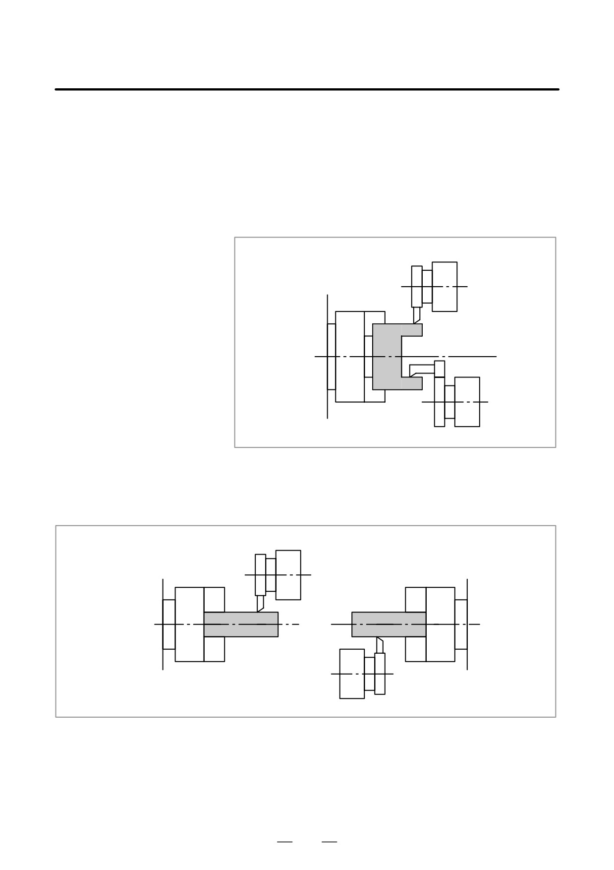
D Application to lathes
Two-path control can be used for a lathe that machines one workpiece
with one spindle and two
attached to one spindle with two tool posts simultaneously.
tool posts
For example, while one tool post is performing outer surface machining,
the other tool post can perform inner surface machining, thus reducing
machining time dramatically.
Tool post 1
Spindle
Tool post 2
Fig. 20.1 (a) Application to lathes with one spindle and tow tool posts
D Application to lathes
Two-path control can be used for a lathe that machines a workpiece
with two spindles and
attached to each of two spindles with two tool posts simultaneously. In
two tool posts
this case, each tool post operates independently of each other as if two
lathes were used, thus improving productivity.
Tool post 1
Spindle 1
Spindle 2
Tool post 2
Fig. 20.1 (b) Application to lathes with two spindles and two tool posts
398