FANUC Series Series 16i-TB, Series 18i-TB, Series 160i-TB, Series 180i-TB. OPERATOR’S MANUAL - page 11
B-63524EN/01
PROGRAMMING
14. COMPENSATION FUNCTION
WARNING
1
When a G28, G30, or G30.1 command is executed when
all-axis machine lock is applied, a vector perpendicular to
the direction in which the tool moves is created at the
intermediate position. In this case, the tool does not move
to the reference position and the offset vector is not
canceled. When bit 2 (CCN) of parameter No. 5003 is set
to 0 or each-axis machine lock is applied, the offset vector
is canceled.
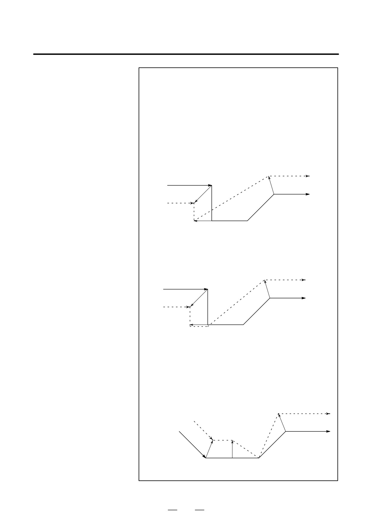
Example 1)
When bit 2 (CCN) of parameter No. 5003 is set to 1.
[FS15 type]
(G42 G01)
s
G28
s G01
G01
r
Reference position or
s
s
floating reference position
Intermediate position
Example 2)
When bit 2 (CCN) of parameter No. 5003 is set to 0 and
all-axis machine lock is applied
[FS15 type]
(G42 G01)
s
G28
s
G01
G01
r
s
Reference position or
s
floating reference position
Intermediate position
2
When a compensation axis is specified in a G28, G30, or
G30.1 command in tool-tip radius compensation mode, the
vectors for other compensation axes are also canceled.
This also applies when bit 2 (CCN) of parameter No. 5003
is set to 1.
(The FS15 cancels only the vector for the
specified axis. Note that the FS15 type cancellation differs
from the actual FS15 specification in this point.)
[FS15 type]
s
s
s
G00
r
G00
(G41 G00 X_ Z_)
Intermediate
Reference position or
G28 Z_
position
floating reference position
279
14. COMPENSATION FUNCTION
PROGRAMMING
B-63524EN/01
NOTE
1
When an axis not included in the tool-tip radius
compensation plane is specified in a G28, G30, or G30.1
command, a vector perpendicular to the direction in which
the tool moves is created at the end of the preceding block
and the tool does not move. Offset mode is automatically
resumed from the next block (in the same way as when two
or more blocks specifying no movement are consecutively
executed).
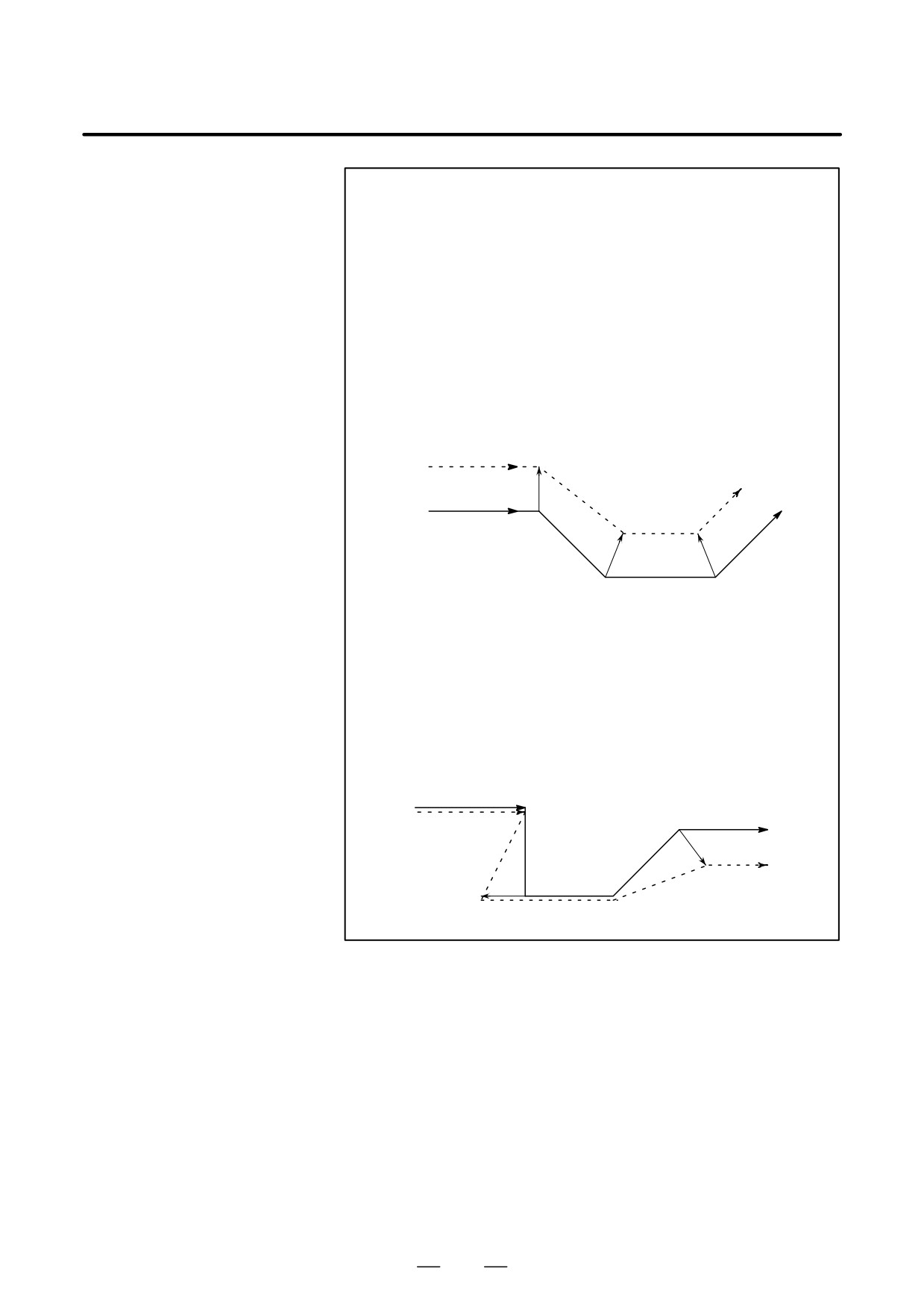
Example)
When bit 2 (CCN) of parameter No. 5003 is set to 1.
[FS15 type]
G28(30/30.1)Y_
r
s
(G41 G01 X_ Z_)
G01
G01
s
G01
s
2
When a G28, G30, or G30.1 command is specified as a
start-up block, a vector perpendicular to the direction in
which the tool moves is created at the intermediate position.
The vector is then canceled at the reference position. The
next block creates an intersection vector.
Example 1)
When bit 2 (CCN) of parameter No. 5003 is set to 1.
[FS15 type]
s
G01
s
G01
G42 G28
G01
s
r
s
Reference position or
Intermediate position
floating reference position
280
B-63524EN/01
PROGRAMMING
14. COMPENSATION FUNCTION
During radius compensation for the tool tip, corner circular-
14.4
interpolation, with the specified compensation value used as the radius,
CORNER CIRCULAR
can be performed by specifying G39 in offset mode.
INTERPOLATION
FUNCTION (G39)
Format
In offset mode, specify
G39;
or
I_J_
G39
I_K_
;
J_K_
Explanations
D Corner
Corner circular-interpolation, with the specified compensation value
circular-interpolation
used as a radius, can be performed by specifying the operation as shown
above. Whether the tool moves clockwise or counterclockwise depends
on whether the last-specified direction code is G41 or G42. G39 is a
single-shot G code.
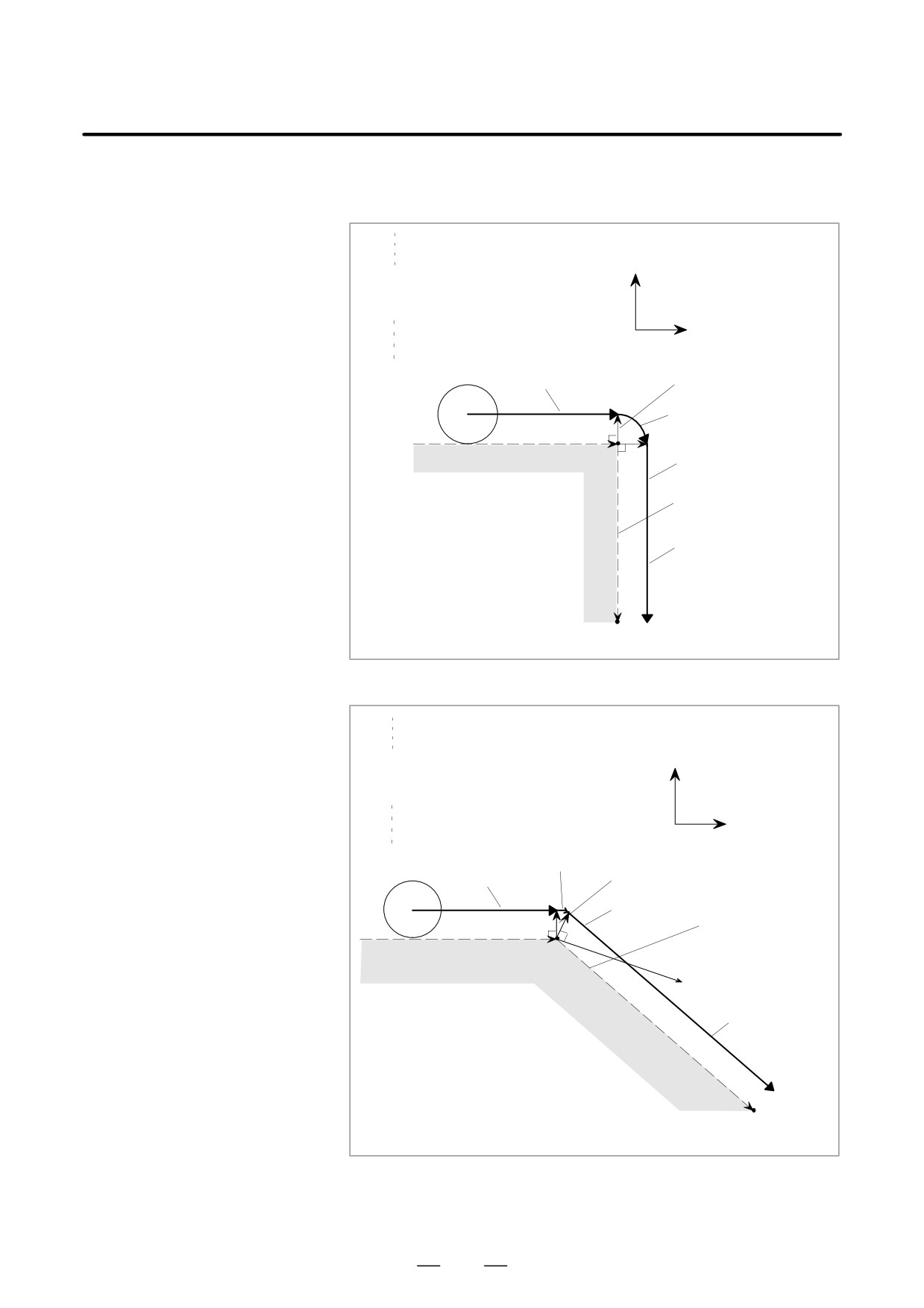
D G39 without I, J, and K
Specifying G39; creates a corner arc for which the end vector is
perpendicular to the start point of the next block.
D G39 with I, J, and K
Specifying G39 I_J_K_; creates a corner arc for which the end vector is
perpendicular to the vector specified with I, J, and K.
Limitations
D Move command
A move operation cannot be specified in a block in which G39 is
specified.
Two or more contiguous blocks with no move operations can not be
D Non-move command
specified immediately after a block in which G39, without I, J, and K, is
specified.
(If a move command is specified in a block with a move
distance of 0, it is assumed to be two or more contiguous blocks with no
more operations.) If those blocks are specified, the offset vector
momentarily disappears and the system automatically returns to offset
mode.
281
14. COMPENSATION FUNCTION
PROGRAMMING
B-63524EN/01
Examples
D G39 without I, J, and K
(In offset mode)
X-axis
N1 Z10.0 ;
N2 G39 ;
N3 X-10.0 ;
Z-axis
Block N1
Offset vector
Block N2
(10.0, 0.0)
Block N3
Programmed
path
Tool-tip center
path
(10.0, -10.0)
D G39 with I, J, and K
(In offset mode)
X-axis
N1 Z10.0 ;
N2 G39 I-1.0 K2.0 ;
N3 X-10.0 Z20.0 ;
Z-axis
Offset vector
Block N1
Block N2
Block N3
Programmed
path
(10.0, 0.0)
(I=-1.0, K=2.0)
Tool-tip center path
(20.0, -10.0)
282
B-63524EN/01
PROGRAMMING
14. COMPENSATION FUNCTION
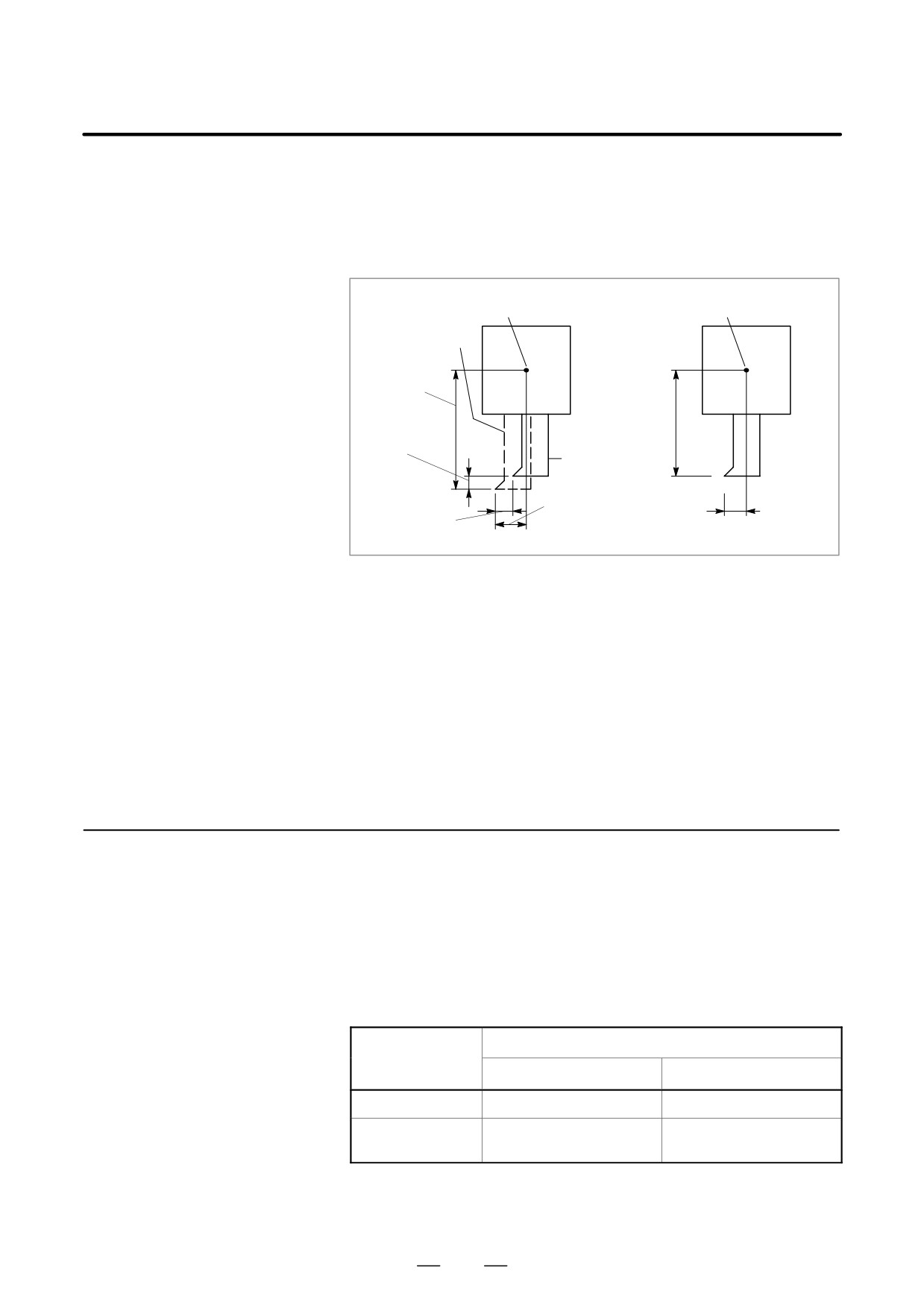
Tool compensation values include tool geometry compensation values
14.5
and tool wear compensation (Fig. 14.5 (a)).
TOOL
Tool compensation can be specified without differentiating compensation
COMPENSATION
for tool geometry from that for tool wear.
VALUES, NUMBER
OF COMPENSATION
Point on the program
Point on the program
VALUES, AND
ENTERING VALUES
Imaginary tool
FROM THE
X axis
geometry
Offset
PROGRAM (G10)
offset
value on
value
X axis
X axis
wear
Actual
offset
tool
value
Z axis
Z axis
wear
geometry
Offset
offset
offset
value on
value
value
Z axis
Fig. 14.5 (a) Difference the
Fig. 14.5 (b) Not difference the
tool geometry offset from tool
tool geometry offset from tool
wear offset
wear offset
Tool compensation values can be entered into CNC memory from the
MDI panel (see section III-9.1) or from a program.
A tool compensation value is selected from the CNC memory when the
corresponding code is specified after address T in a program.
The value is used for tool offset or tool nose radius compensation.
See subsec. II-14.1.2 for details.
14.5.1
Tool Compensation
and Number of Tool
Compensation
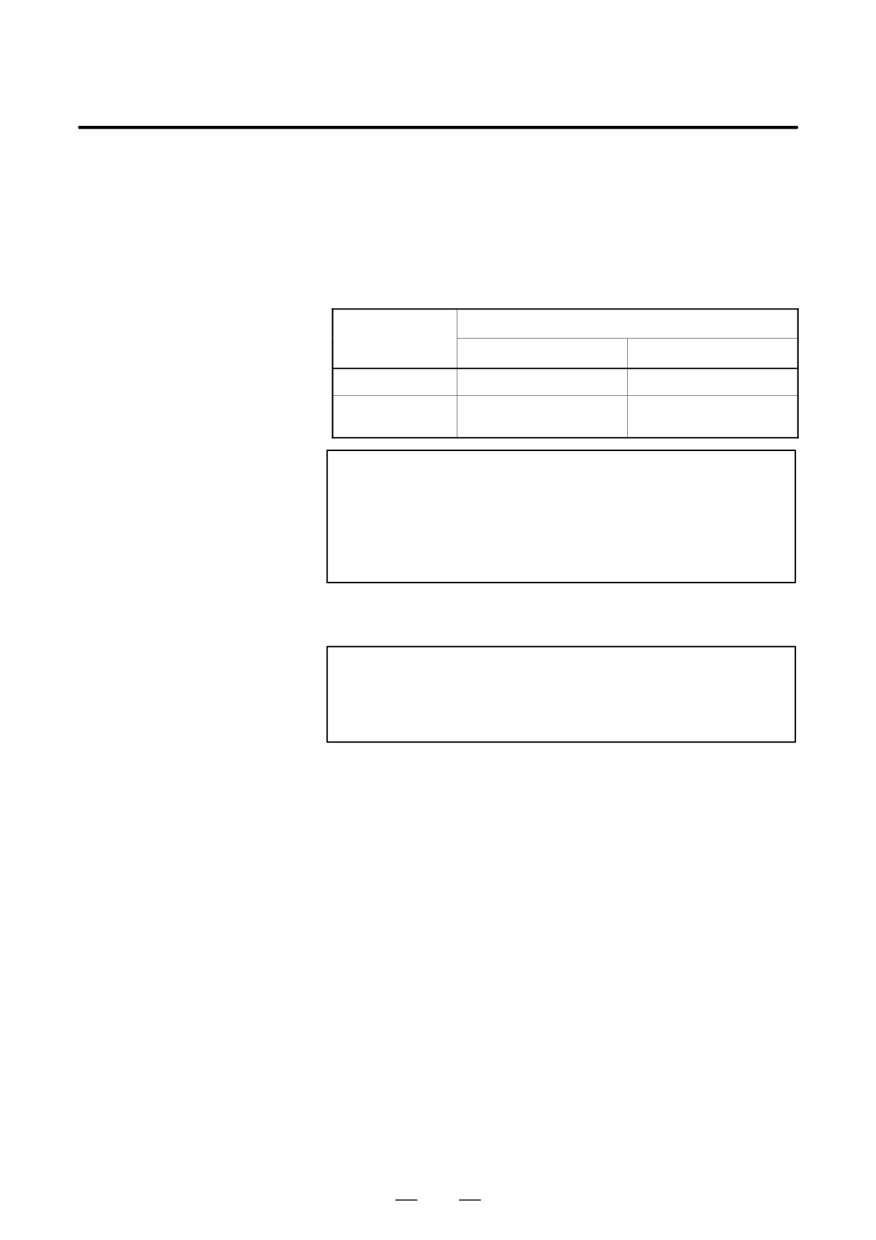
D Valid range of tool
Table 14.5.1 (a) shows the valid input range of tool compensation values.
compensation values
Table 14.5.1 (a) Valid range of tool compensation values
Tool compensation value
Increment system
Metric input (mm)
Inch input (inch)
IS-B
-999.999 to +999.999 mm
-99.9999 to +99.9999 inch
IS-C
-999.9999 to +999.9999
-99.99999 to +99.99999
mm
inch
The maximum tool wear compensation can be changed by setting
parameter No. 5013.
283
14. COMPENSATION FUNCTION
PROGRAMMING
B-63524EN/01
D Seven-digit tool offset
The number of digits used to specify a tool geometry/wear compensation
specification
value can be expanded by selecting the option which enables seven-digit
tool offset specification. When this option is used, tool compensation
values can be specified using up to seven digits for IS-B and eight digits
for IS-C. The valid data range for tool compensation values will thus be
as listed in Table 14.5.1(b).
Table 14.5.1 (b)
Increment system
Tool compensation value
Metric input (mm)
Inch input (inch)
IS-B
0 to "9999.999 mm
0 to "999.9999 inch
IS-C
0 to "9999.9999 mm
0 to "999.99999 inch
(0 to "4000.0000 mm)
(0 to "160.00000 inch)
NOTE
1
The range enclosed in parentheses applies when automatic
inch/metric conversion is enabled (bit 0 (OIM) of parameter
No. 5006 is set to 1).
2
The option enabling seven-digit tool offset specification
cannot be used for B-axis offsets for B-axis control.
D Number of tool
The memory can hold 16, 32, 64, or 99 tool compensation values.
compensation
NOTE
With the two-path control, the number of specified tool
compensation values equals the number of tool
compensations for each tool post.
284

B-63524EN/01
PROGRAMMING
14. COMPENSATION FUNCTION
14.5.2
Offset values can be input by a program using the following command :
Changing of Tool
Offset Value
(Programmable Data
Input ) (G10)
Format
G10 P_ X_ Y_ Z_ R_ Q_ ;
or
G10 P_ U_ V_ W_ C_ Q_ ;
P : Offset number
0
: Command of work coordinate system shift value
1-64 : Command of tool wear offset value
Command value is offset number
10000+(1-64) : Command of tool geometry offset value
(1-64) : Offset number
X : Offset value on X axis (absolute)
Y : Offset value on Y axis (absolute)
Z : Offset value on Z axis (absolute)
U : Offset value on X axis (incremental)
V : Offset value on Y axis (incremental)
W: Offset value on Z axis (incremental)
R : Tool nose radius offset value (absolute)
R : Tool nose radius offset value (incremental)
Q: Imaginary tool nose number
In an absolute command, the values specified in addresses X, Y , Z, and
R are set as the offset value corresponding to the offset number specified
by address P. In an incremental command, the value specified in
addresses U, V, W, and C is added to the current offset value
corresponding to the offset number.
NOTE
1
Addresses X, Y, Z, U, V, and W can be specified in the same
block.
2
Use of this command in a program allows the tool to
advance little by little. This command can also be used input
offset values one at a time from a program by specifying this
command successively instead of inputting these values
one at a time from the MDI unit.
285
14. COMPENSATION FUNCTION
PROGRAMMING
B-63524EN/01
When a tool is moved to the measurement position by execution of a
14.6
command given to the CNC, the CNC automatically measures the
AUTOMATIC TOOL
difference between the current coordinate value and the coordinate value
OFFSET (G36, G37)
of the command measurement position and uses it as the offset value for
the tool. When the tool has been already offset, it is moved to the
measurement position with that offset value. If the CNC judges that
further offset is needed after calculating the difference between the
coordinate values of the measurement position and the commanded
coordinate values, the current offset value is further offset.
Refer to the instruction manuals of the machine tool builder for details.
Explanations
D Coordinate system
When moving the tool to a position for measurement, the coordinate
system must be set in advance.
(The work coordinate system for
programming is used in common.)
D Movement to
A movement to a measurement position is performed by specifying as
measurement position
follows in the MDI, or MEM mode :
G36 Xxa ; or G37 Zza ;
In this case, the measurement position should be xa or za (absolute
command).
Execution of this command moves the tool at the rapid traverse rate
toward the measurement position, lowers the feedrate halfway, then
continues to move it until the approach end signal from the measuring
instrument is issued. When the tool tip reaches the measurement position,
the measuring instrument outputs the measurement position reach signal
to the CNC which stops the tool.
D Offset
The current tool offset value is further offset by the difference between the
coordinate value (α or β) when the tool has reached the measurement
position and the value of xa or za specified in G36Xxa or G37Zza.
Offset value x = Current offset value x+(α-xa)
Offset value z = Current offset value z+(β-za)
xa : Programmed X-axis measurement point
za : Programmed Z-axis measurement point
These offset values can also be altered from the MDI keyboard.
286
B-63524EN/01
PROGRAMMING
14. COMPENSATION FUNCTION
D Feedrate and alarm
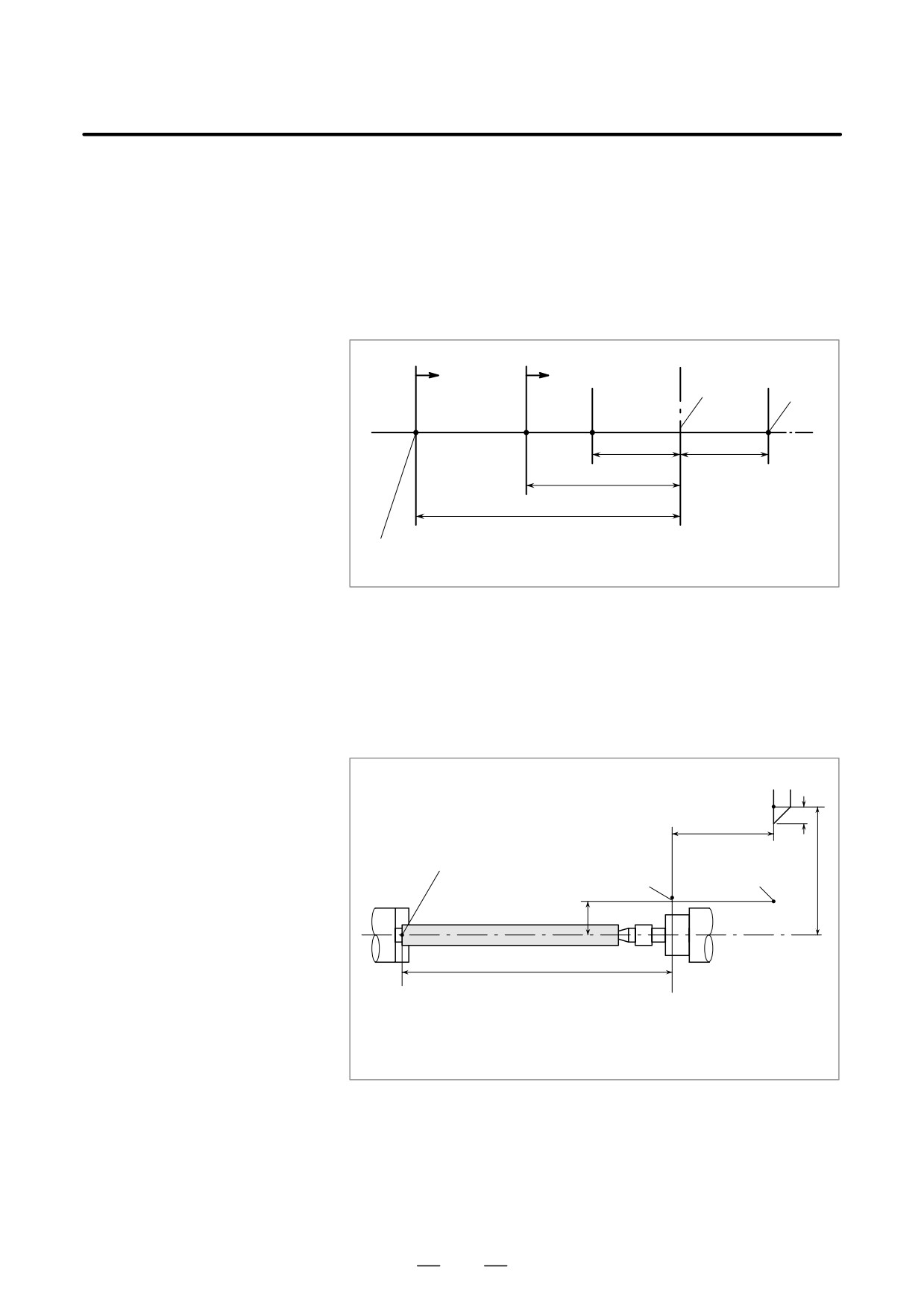
The tool, when moving from the stating position toward the measurement
position predicted by xa or za in G36 or G37, is fed at the rapid traverse
rate across area A. Then the tool stops at point T (xa-γx or za-γz) and
moves at the measurement feedrate set by parameter (No. 6241) across
areas B, C, and D. If the approach end signal turns on during movement
across area B, alarm is generated. If the approach end signal does not turn
on before point V, and tool stops at point V and P/S alarm (No. 080) is
generated.
Predicted measurement position
FR
FP
U
V
X, Z
A
B
C
D
S (xs, zs)
T
ε
ε
γ
|xa-xs|. |za-zs|
U (xa, za)
Starting position
FR : Rapid traverse rate
FP : Measurement feedrate (set by parameter(No.6241))
Fig. 14.6 Feedrate and Alarm
D G code
If bit 3 (G36) of parameter No. 3405 has been set to 1, G37.1 and G37.2
are used as the G codes for automatic tool compensation for the X- and
Z-axes, respectively.
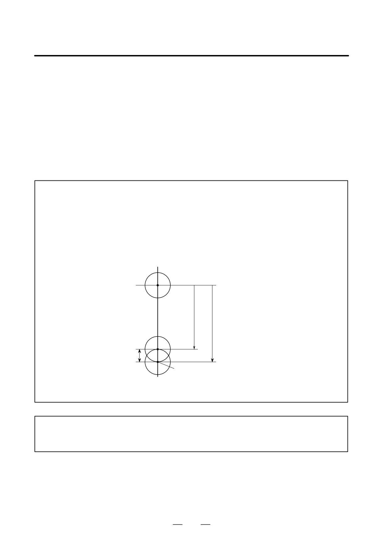
Examples
Tool number T1
50
300
Programmed
X-axis
zero point
Z-axis measurement
measurement
position
position
380
100
ÇÇ
ÇÇ
800
ÇÇ
Offset value
Offset value
(Before measurement) (After measurement)
X 100.0
98.0
Z0
4.0
G50 X760.0 Z1100.0 ;
Programming of absolute zero point
(Coordinate system setting)
S01 M03 T0101 ;
Specifies tool T1, offset number 1, and spindle
revolution
287
14. COMPENSATION FUNCTION
PROGRAMMING
B-63524EN/01
G36 X200.0 ;
Moves to the measurement position
If the tool has reached the measurement position
at X198.0
; since the correct measurement
position is 200 mm, the offset value is altered by
198.0-200.0=-2.0mm.
G00 X204.0 ;
Refracts a little along the X axis.
G37 Z800.0 ;
Moves to the Z-axis measurement position.
If the tool has reached the measurement position
at X804.0, the offset value is altered by
804.0-800.0=4.0mm.
T0101 ;
Further offsets by the difference.
The new offset value becomes valid when the T
code is specified again.
WARNING
1
Measurement speed(Fp), γ, and ε are set as parameters (Fp : No.6241, γ : No.6251,
ε : No.6254) by machine tool builder. ε must be positive numbers so that γ>ε.
2
Cancel the tool nose radius compensation before G36, G37.
3
When a manual movement is inserted into a movement at a measurement feedrate, return the
tool to the position before the inserted manual movement for restart.
4
When using the optional tool nose radius compensation function, the tool offset amount is
determined considering the value of tool nose R. Make sure that tool nose radius value is set
correctly.
Example) When the tool nose center coincides with the start point.
A
Actual
Movement coinsidering
movement
tool nose radius value
B
Tool nose radius value
C Measurement position
The tool actually moves from point A to point B, but the tool offset value is determined assuming
that the tool moves to point C considering the tool nose radius value.
NOTE
1
When there is no T code command before G36 or G37, P/S alarm No.81 is generated.
2
When a T code is specified in the same block as G36 or G37, P/S alarm No.82 is generated.
288
B-63524EN/01
PROGRAMMING
14. COMPENSATION FUNCTION
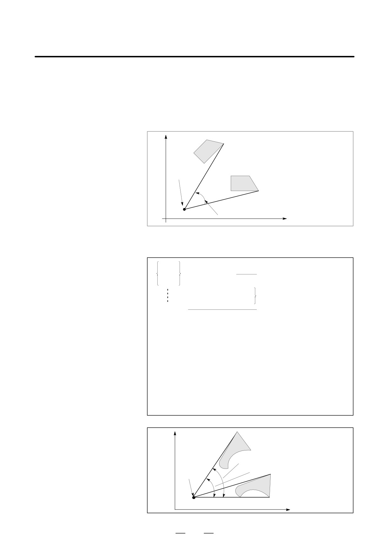
With the coordinate rotation function, it is possible to rotate a figure
14.7
specified in a program. For example, a program that produces patterns
COORDINATE
of a figure rotated at increasingly larger angles can be created as a pair of
ROTATION
subprograms, one of which defines a figure, the other of which calls the
(G68.1, G69.1)
figure definition subprogram by specifying rotation. This method is
useful for reducing the program development time and the size of the
program.
X
Rotation
center
Rotation angle
Z
Format
G17
G18
G68.1 α_ β_ R_ ;
Starts rotating the coordinates
G19
Coordinate rotation mode
(the coordinates are rotated)
G69.1 ;
Cancels coordinate rotation
G17 (G18 or G19) :
Selects a plane where the figure to be rotated is
α, β :
Specify two coordinates (from among X, Y, and Z) of the rotation cen-
ter that match G17, G18, and G19. The values specified as the coor-
dinates of the rotation center must always be absolute values.
R:
Specifies the rotation angle as an absolute value. Counterclockwise
rotation is assumed to be positive. However, setting bit 0 (RIN) of
parameter No. 5400 enables the use of an incremental value.
Incremental units of the angle: 0.001 degrees
Specifiable range: -360,000 to +360,000
X
Rotation angle R (incremental value)
Rotation
Rotation angle R (absolute value)
center
(α, β)
Z
289
14. COMPENSATION FUNCTION
PROGRAMMING
B-63524EN/01
Explanations
D Plane selection G code,
Plane selection G code (G17, G18, or G19) can be specified in a block
G17, G18, or G19
ahead of the coordinate rotation G code (G68.1). Do not specify G17,
G18, or G19 in coordinate rotation mode.
D Rotation center
If the rotation center (α_, β_) is not specified, the location of the tool when
G68.1 is issued is assumed as the rotation center.
D Rotation angle command
If the rotation angle command (R_) is not specified, the value specified
in parameter No. 5410 is used as the rotation angle.
D Coordinate rotation
The coordinate rotation cancel G code (G69.1) can be specified in the
cancel
same block as other commands.
D Tool compensation
Tool compensation, such as tool offset or tool nose radius compensation,
is processed after coordinate rotation is performed for a program defining
a figure.
G68.1 can be used in either G00 or G01 mode.
Limitations
D Reference position
A reference position return command G27, G28, G29, or G30 can be
return
issued only in G69.1 mode.
D Changes to coordinates
Do not attempt to change coordinates in G68.1 mode (commands such as
G50, G54 to G59, and the tool offset command).
D Canned cycles
Coordinate rotation cannot be used in simple canned cycles, multiple
repetitive canned cycles, or canned drilling cycles.
Always use absolute values in a move command that immediately follows
D Incremental command
the coordinate rotation command (G68.1) or coordinate rotation cancel
command (G69.1). Specifying an incremental value results in the move
command failing to operate normally.
290
B-63524EN/01
PROGRAMMING
14. COMPENSATION FUNCTION
Examples
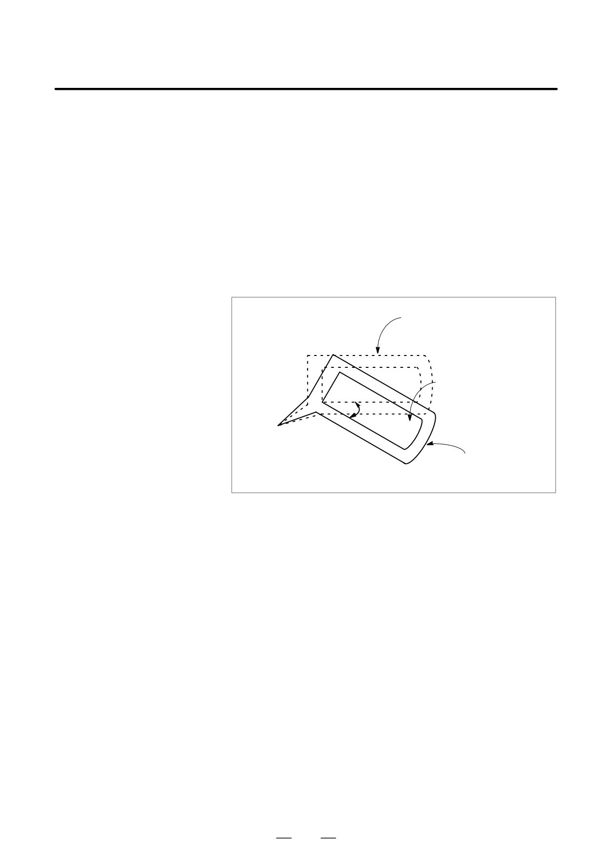
D Tool nose radius and
G68.1 and G69.1 can be specified during tool nose radius compensation,
coordinate rotation
provided that the coordinate rotation plane coincides with the tool nose
radius compensation plane.
N1 G50 X0 Z0 G69.1 G01 ;
N2 G42 X1000 Z1000 F1000 T0101 ;
N3 G68 R-30000 ;
N4 Z3000 ;
N5 G03 U1000 R1000 ;
N6 G01 Z1000 ;
N7 U-1000 ;
N8 G69.1 G40 X0 Z0 ;
Program before rotation
Program after rotation
30°
(0, 0)
Tool path
291
14. COMPENSATION FUNCTION
PROGRAMMING
B-63524EN/01
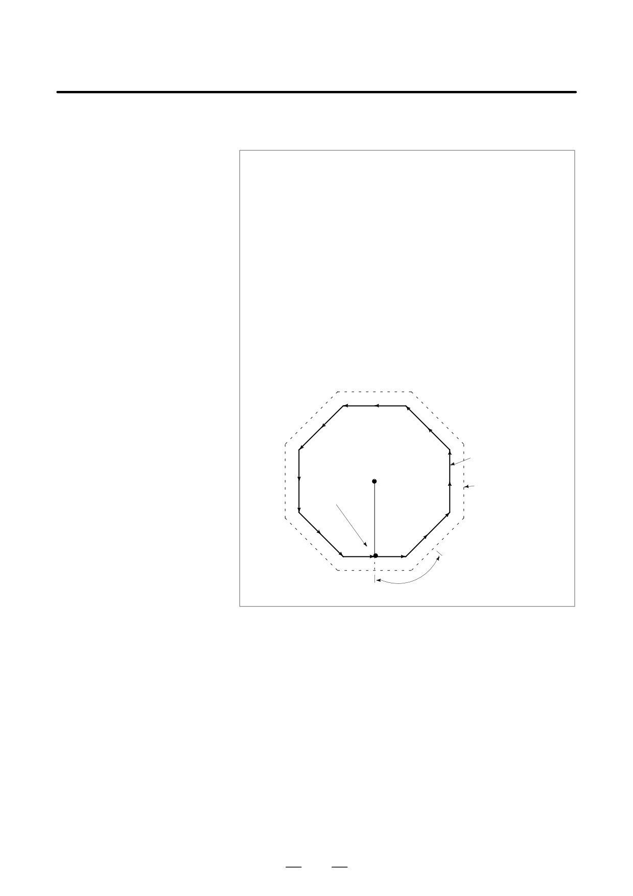
D Repetitive coordinate
Coordinate rotation can be repeated by calling a registered subprogram
rotation
more than once, but with increasingly greater rotation angles.
Set bit 0 (RIN) of parameter No. 5400 to 1 to specify the rotation
angle as being incremental. (G code A, radius programming along
the X-axis)
G50 X0 Z0 G18 ;
G01 F200 T0101 ;
M98 P2100 ;
M98 P2200 L7 ;
G00 X0 Z0 M30 ;
O2200 ;
G68.1 X0 Z0 R45.0 ;
G90 M98 P2100 ;
M99 ;
O2100 ;
G01 G42 X-10.0 Z0 ;
X-10.0 Z4.142 ;
X-7.071 Z7.071 ;
G40 M99 ;
Programmed tool path
(0, 0)
Tool path with an
offset
(0, -10.0)
Subprogram
292
B-63524EN/01
PROGRAMMING
15. CUSTOM MACRO
CUSTOM MACRO
15
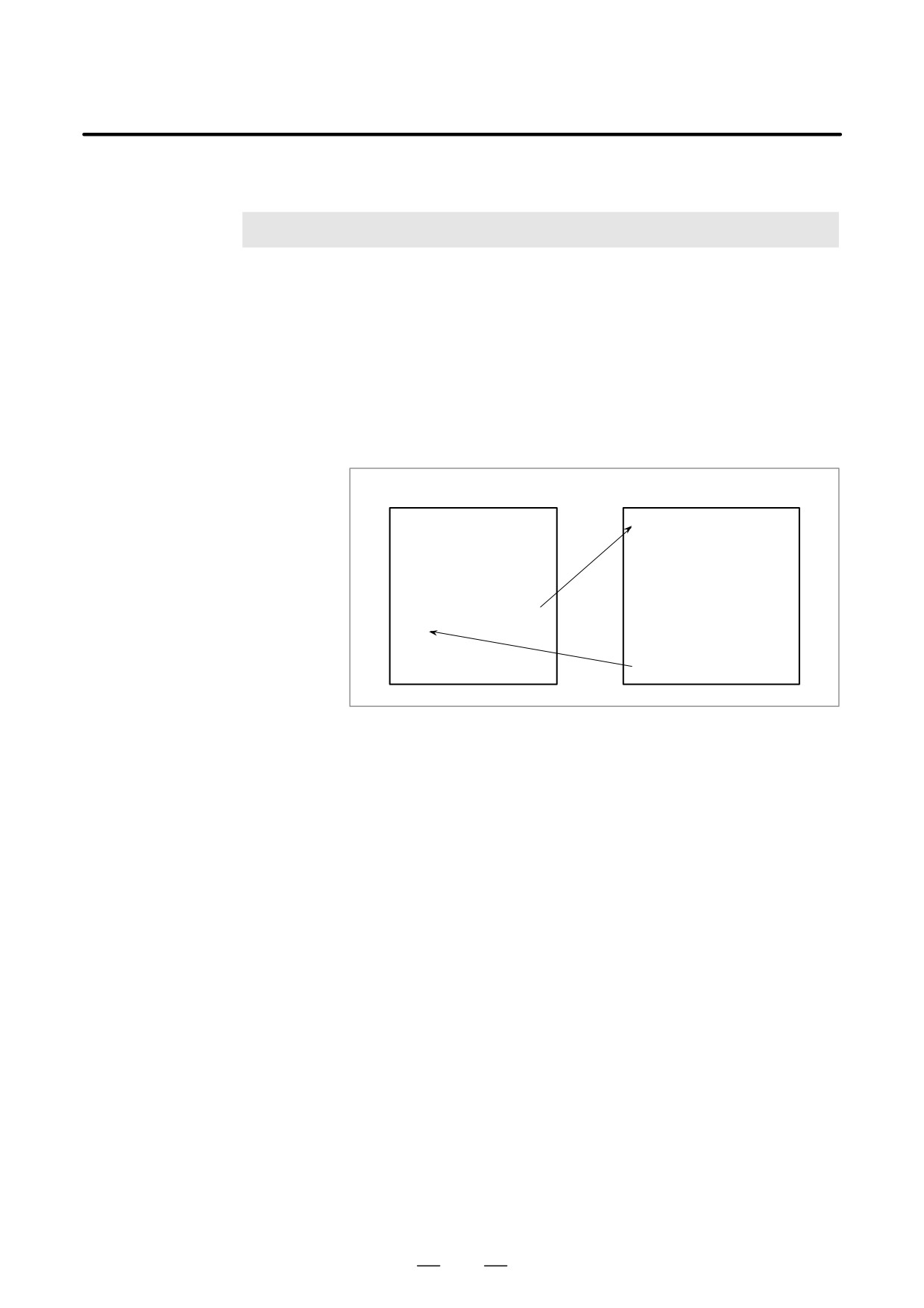
Although subprograms are useful for repeating the same operation, the
custom macro function also allows use of variables, arithmetic and logic
operations, and conditional branches for easy development of general
programs such as pocketing and user-defined canned cycles. A
machining program can call a custom macro with a simple command, just
like a subprogram.
Machining program
Custom macro
O0001 ;
O9010 ;
:
#1=#18/2 ;
:
G01 X#1 Z#1 F0.3 ;
:
G02 X#1 Z-#1 R#1 ;
G65 P9010 R50.0 L2 ;
:
:
:
:
:
M30 ;
M99 ;
293
15. CUSTOM MACRO
PROGRAMMING
B-63524EN/01
An ordinary machining program specifies a G code and the travel distance
15.1
directly with a numeric value; examples are G100 and X100.0.
VARIABLES
With a custom macro, numeric values can be specified directly or using
a variable number. When a variable number is used, the variable value
can be changed by a program or using operations on the MDI panel.
#1=#2+100 ;
G01 X#1 F0.3 ;
Explanation
D Variable representation
When specifying a variable, specify a number sign (#) followed by a
variable number. General-purpose programming languages allow a name
to be assigned to a variable, but this capability is not available for custom
macros.
Example: #1
An expression can be used to specify a variable number. In such a case,
the expression must be enclosed in brackets.
Example: #[#1+#2-12]
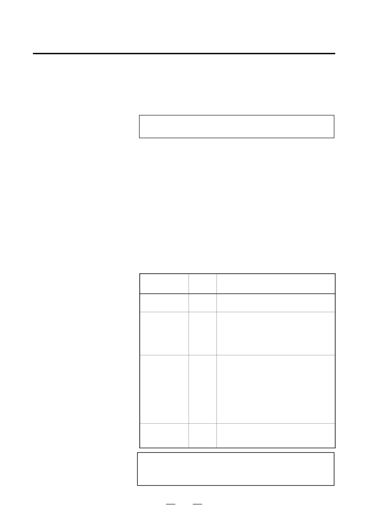
D Types of variables
Variables are classified into four types by variable number.
Table 15.1 Types of variables
Variable
Type of
Function
number
variable
#0
Always
This variable is always null. No value can be
null
assigned to this variable.
#1 - #33
Local
Local variables can only be used within a
variables
macro to hold data such as the results of op-
erations. When the power is turned off, local
variables are initialized to null. When a macro
is called, arguments are assigned to local vari-
ables.
#100 - #149
Common
Common variables can be shared among dif-
variables
ferent macro programs. When the power is
(#199)
turned off, variables #100 to #149 are initial-
#500 - #531
ized to null. Variables #500 to #531 hold data
even when the power is turned off. As an op-
(#999)
tion, common variables #150 to #199 and
#532 to #999 are also available. However,
when these values are using, the length of the
tape that can be used for storage decreases
by 8.5 m.
#1000 or later
System
System variables are used to read and write a
variables
variety of NC data items such as the current
position and tool compensation values.
NOTE
Common variables #150 to #199 and #532 to #999 are
optional.
294
B-63524EN/01
PROGRAMMING
15. CUSTOM MACRO
D Range of variable values
Local and common variables can have value 0 or a value in the following
ranges :
-1047 to -10-29
0
+10-29 to +1047
If the result of calculation turns out to be invalid, an P/S alarm No. 111
is issued.
D Omission of the decimal
When a variable value is defined in a program, the decimal point can be
point
omitted.
Example:
When #1=123; is defined, the actual value of variable #1 is
123.000.
To reference the value of a variable in a program, specify a word address
D Referencing variables
followed by the variable number. When an expression is used to specify
a variable, enclose the expression in brackets.
Example: G01X[#1+#2]F#3;
A referenced variable value is automatically rounded according to the
least input increment of the address.
Example:
When G00X#1; is executed on a 1/1000-mm CNC with 12.3456
assigned to variable #1, the actual command is interpreted as
G00X12.346;.
To reverse the sign of a referenced variable value, prefix a minus sign (-)
to #.
Example: G00X-#1;
When an undefined variable is referenced, the variable is ignored up to an
address word.
Example:
When the value of variable #1 is 0, and the value of variable #2 is
null, execution of G00X#1Z#2; results in G00X0;.
D Undefined variable
When the value of a variable is not defined, such a variable is referred to
as a ”null” variable. Variable #0 is always a null variable. It cannot be
written to, but it can be read.
(a) Quotation
When an undefined variable is quotated, the address itself is also
ignored.
When #1 = < vacant >
When #1 = 0
G90 X100 Y#1
G90 X100 Y#1
#
#
G90 X100
G90 X100 Y0
295
15. CUSTOM MACRO
PROGRAMMING
B-63524EN/01
(b)Operation
< vacant > is the same as 0 except when replaced by < vacant>
When #1 = < vacant >
When #1 = 0
#2 = #1
#2 = #1
#
#
#2 = < vacant >
#2 = 0
#2 = #1*5
#2 = #1*5
#
#
#2 = 0
#2 = 0
#2 = #1+#1
#2 = #1 + #1
#
#
#2 = 0
#2 = 0
(c) Conditional expressions
< vacant > differs from 0 only for EQ and NE.
When #1 = < vacant >
When #1 = 0
#1 EQ #0
#1 EQ #0
#
#
Established
Not established
#1 NE 0
#1 NE 0
#
#
Established
Not established
#1 GE #0
#1 GE #0
#
#
Established
Established
#1 GT 0
#1 GT 0
#
#
Not established
Not established
D Custom macro variables
With the two-path control, macro variables are provided for each tool
common to tool posts
post. Specifying parameter Nos. 6036 and 6037 allows some of the
(two-path control)
common variables to be used for all tool posts.
296

B-63524EN/01
PROGRAMMING
15. CUSTOM MACRO
D Displaying variable
values
VARIABLE
O1234 N12345
NO.
DATA
NO.
DATA
100 123.456108
101 0.000 109
102
110
103 ******** 111
104
112
105
113
106
114
107
115
ACTUAL POSITION (RELATIVE)
X
0.000
Y
0.000
Z
0.000
B
0.000
MEM **** *** ***
18:42:15
[ MACRO ] [ MENU ] [ OPR
] [
] [ (OPRT) ]
D When the value of a variable is blank, the variable is null.
D The mark ******** indicates an overflow (when the absolute
value of a variable is greater than 99999999) or an underflow (when
the absolute value of a variable is less than 0.0000001).
Limitations
Program numbers, sequence numbers, and optional block skip numbers
cannot be referenced using variables.
Example:
Variables cannot be used in the following ways:
O#1;
/#2G00X100.0;
N#3Z200.0;
297
15. CUSTOM MACRO
PROGRAMMING
B-63524EN/01
System variables can be used to read and write internal NC data such as
15.2
tool compensation values and current position data. Note, however, that
SYSTEM VARIABLES
some system variables can only be read. System variables are essential
for automation and general-purpose program development.
Explanations
D Interface signals
Signals can be exchanged between the programmable machine controller
(PMC) and custom macros.
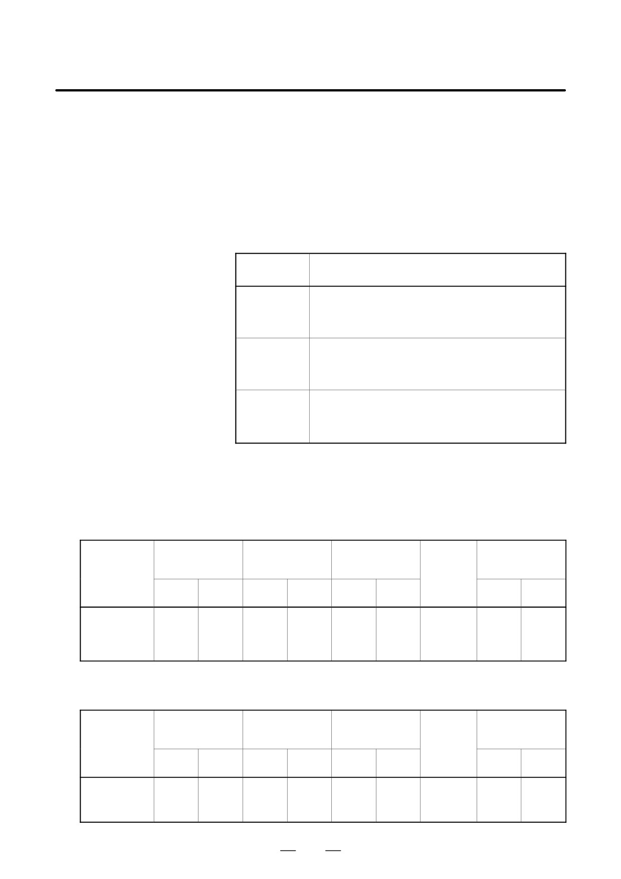
Table 15.2 (a) System variables for interface signals
Variable
Function
number
#1000-#1015
A 16-bit signal can be sent from the PMC to a custom
macro. Variables #1000 to #1015 are used to read a sig-
#1032
nal bit by bit. Variable #1032 is used to read all 16 bits of
a signal at one time.
#1100-#1115
A 16-bit signal can be sent from a custom macro to the
PMC. Variables #1100 to #1115 are used to write a signal
#1132
bit by bit. Variable #1132 is used to write all 16 bits of a
signal at one time.
#1133
Variable #1133 is used to write all 32 bits of a signal at one
time from a custom macro to the PMC.
Note, that values from -99999999 to +99999999 can be
used for #1133.
For detailed information, refer to the connection manual
(B-63523EN-1).
D Tool compensation
When the system does not differentiate tool geometry compensation from
values
tool wear compensation, use variable numbers for wear compensation.
Table 15.2 (b) System variables for tool compensation memory C
X axis
Z axis
Tool nose radius
Y axis
compensation
compensation
compensation
compensation
Imaginary
Compensation
value
value
value
value
tool nose
number
position T
Geome-
Geome-
Geome-
Geome-
Wear
Wear
Wear
Wear
try
try
try
try
1
#2001
#2701
#2101
#2801
#2201
#2901
#2301
#2401
#2451
:
:
:
:
:
:
:
:
:
:
49
:
#2749
:
#2849
:
:
:
#2449
#2499
:
:
:
:
:
:
64
#2064
#2164
#2264
#2964
#2364
Table 15.2 (c) System variables for 99 tool compensation values
X axis
Z axis
Tool nose radius
Y axis
compensation
compensation
compensation
compensation
Imaginary
Compensation
value
value
value
value
tool nose
number
position T
Geome-
Geome-
Geome-
Geome-
Wear
Wear
Wear
Wear
try
try
try
try
1
#10001
#15001
#11001
#16001
#12001
#17001
#13001
#14001
#19001
:
:
:
:
:
:
:
:
:
:
:
:
:
:
:
:
:
:
:
:
99
#10099
#15099
#11099
#16099
#12099
#17099
#13099
#14099
#19099
298
B-63524EN/01
PROGRAMMING
15. CUSTOM MACRO
Workpiece coordinate
A workpiece coordinate system shift amount can be read. The amount can
system shift amount
also be changed by entering a value.
Controlled axis
Workpiece coordinate system shift amount
X axis
#2501
Z axis
#2601
D Macro alarms
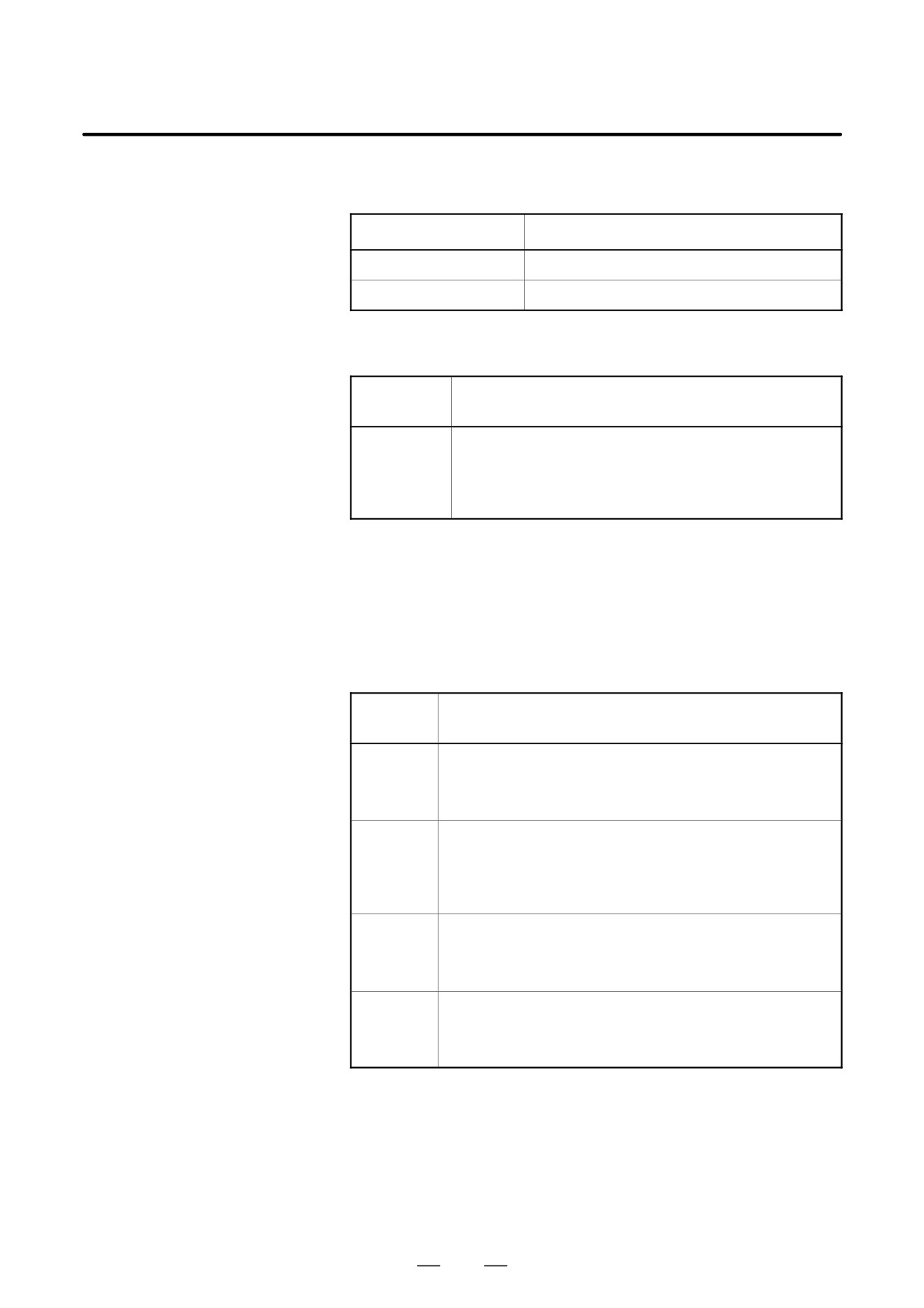
Table 15.2 (d) System variable for macro alarms
Variable
Function
number
#3000
When a value from 0 to 200 is assigned to variable #3000,
the CNC stops with an alarm. After an expression, an alarm
message not longer than 26 characters can be described.
The CRT screen displays alarm numbers by adding 3000 to
the value in variable #3000 along with an alarm message.
Example:
#3000=1(TOOL NOT FOUND);
→ The alarm screen displays “3001 TOOL NOT FOUND.”
D Time information
Time information can be read and written.
Table 15.2 (e) System variables for time information
Variable
Function
number
#3001
This variable functions as a timer that counts in 1-millisecond
increments at all times. When the power is turned on, the
value of this variable is reset to 0. When 2147483648 milli-
seconds is reached, the value of this timer returns to 0.
#3002
This variable functions as a timer that counts in 1-hour incre-
ments when the cycle start lamp is on. This timer preserves
its value even when the power is turned off. When
9544.371767 hours is reached, the value of this timer returns
to 0.
#3011
This variable can be used to read the current date (year/
month/day). Year/month/day information is converted to an
apparent decimal number. For example, March 28, 1993 is
represented as 19930328.
#3012
This variable can be used to read the current time (hours/min-
utes/seconds). Hours/minutes/seconds information is con-
verted to an apparent decimal number. For example, 34 min-
utes and 56 seconds after 3 p.m. is represented as 153456.
299
15. CUSTOM MACRO
PROGRAMMING
B-63524EN/01
D Automatic operation
The control state of automatic operation can be changed.
control
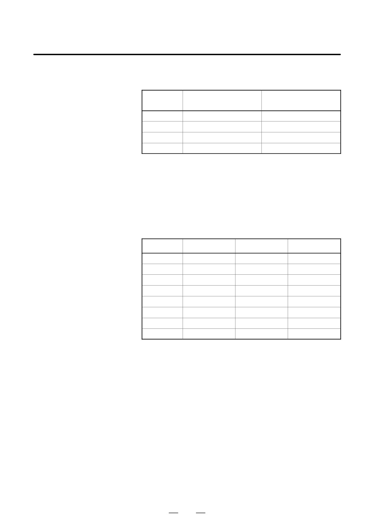
Table 15.2 (f) System variable (#3003) for automatic operation control
#3003
Single block
Completion of an auxiliary
function
0
Enabled
To be awaited
1
Disabled
To be awaited
2
Enabled
Not to be awaited
3
Disabled
Not to be awaited
D When the power is turned on, the value of this variable is 0.
D When single block stop is disabled, single block stop operation is not
performed even if the single block switch is set to ON.
D When a wait for the completion of auxiliary functions (M, S, and T
functions) is not specified, program execution proceeds to the next
block before completion of auxiliary functions. Also, distribution
completion signal DEN is not output.
Table 15.2 (g) System variable (#3004) for automatic operation control
#3004
Feed hold
Feedrate Override
Exact stop
0
Enabled
Enabled
Enabled
1
Disabled
Enabled
Enabled
2
Enabled
Disabled
Enabled
3
Disabled
Disabled
Enabled
4
Enabled
Enabled
Disabled
5
Disabled
Enabled
Disabled
6
Enabled
Disabled
Disabled
7
Disabled
Disabled
Disabled
D
When the power is turned on, the value of this variable is 0.
D
When feed hold is disabled:
(1) When the feed hold button is held down, the machine stops in the
single block stop mode. However, single block stop operation is
not performed when the single block mode is disabled with
variable #3003.
(2) When the feed hold button is pressed then released, the feed hold
lamp comes on, but the machine does not stop; program execution
continues and the machine stops at the first block where feed hold
is enabled.
D
When feedrate override is disabled, an override of 100% is always
applied regardless of the setting of the feedrate override switch on the
machine operator’s panel.
D
When exact stop check is disabled, no exact stop check (position
check) is made even in blocks including those which do not perform
cutting.
300
B-63524EN/01
PROGRAMMING
15. CUSTOM MACRO
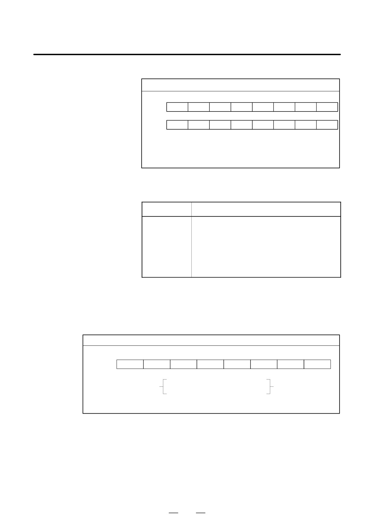
D Settings
Settings can be read and written. Binary values are converted to decimals.
#3005
#15
#14
#13
#12
#11
#10
#9
#8
Setting
FCV
#7
#6
#5
#4
#3
#2
#1
#0
Setting
SEQ
INI
ISO
TVC
#9 (FCV)
: Whether to use the FS15 tape format conversion capability
#5 (SEQ) : Whether to automatically insert sequence numbers
#2 (INI) : Millimeter input or inch input
#1 (ISO): Whether to use EIA or ISO as the output code
#0 (TVC)
: Whether to make a TV check
D Stop with a message
Execution of the program can be stopped, and then a message can be
displayed.
Variable number
Function
#3006
When “#3006=1 (MESSAGE);” is commanded in the
macro, the program executes blocks up to the immediate-
ly previous one and then stops.
When a message of up to 26 characters, which is en-
closed by a control-in character (“(”) and control-out
character (“)”), is programmed in the same block, the
message is displayed on the external operator message
screen.
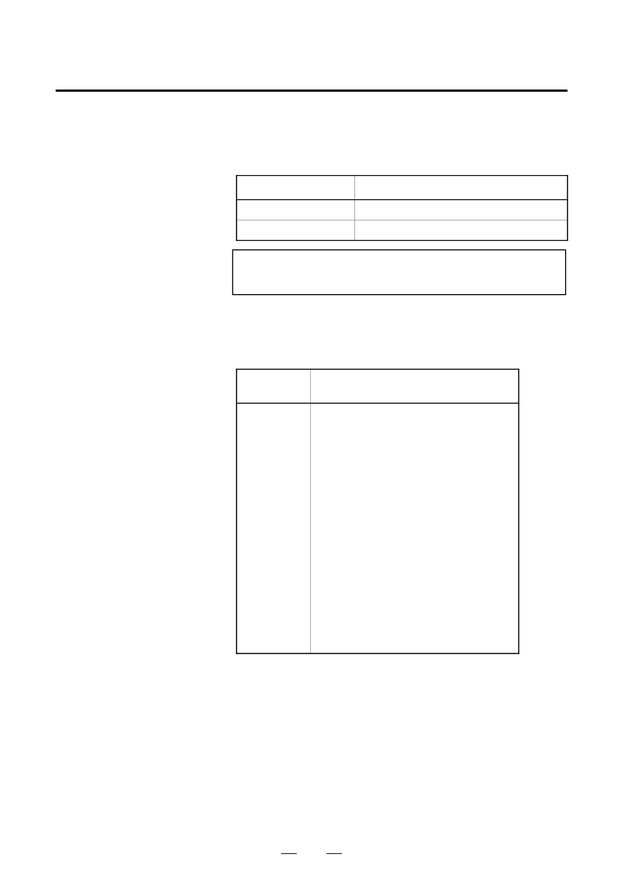
D Mirror image
The mirror-image status for each axis set using an external switch or
setting operation can be read through the output signal (mirror-image
check signal). The mirror-image status present at that time can be
checked. (See Section 4.7 in III.)
The value obtained in binary is converted into decimal notation.
#3007
#7
#6
#5
#4
#3
#2
#1
#0
Setting
8th axis
7th axis
6th axis
5th axis
4th axis
3th axis
2th axis
1th axis
0 (mirror-image function is disabled)
For each bit,
or
is indicated.
1 (mirror-image function is enabled)
Example : If #3007 is 3, the mirror-image function is enabled for the first and second axes.
D When the mirror-image function is set for a certain axis by both the
mirror-image signal and setting, the signal value and setting value are
ORed and then output.
D When mirror-image signals for axes other than the controlled axes are
turned on, they are still read into system variable #3007.
D System variable #3007 is a write-protected system variable. If an
attempt is made to write data in the variable, P/S 116 alarm “WRITE
PROTECTED VARIABLE” is issued.
301
15. CUSTOM MACRO
PROGRAMMING
B-63524EN/01
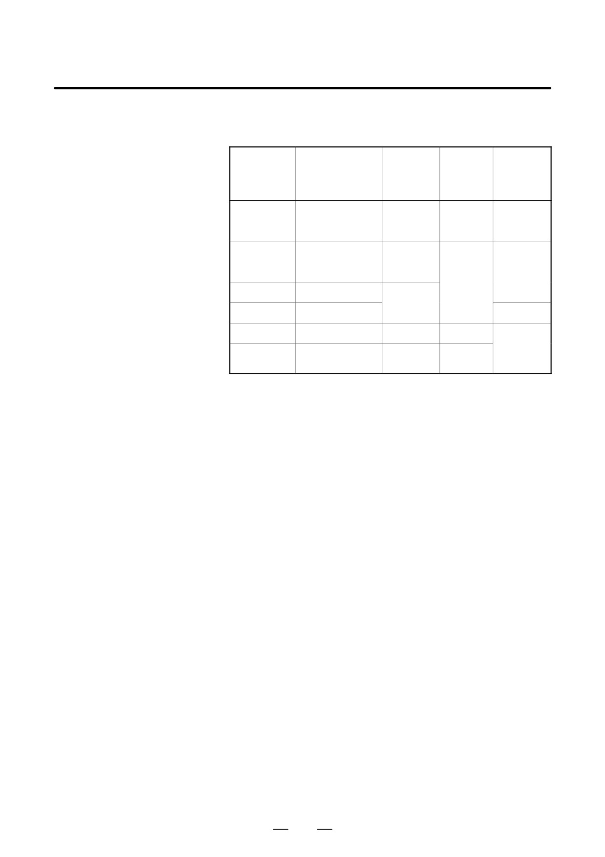
D Number of machined
The number (target number) of parts required and the number (completion
parts
number) of machined parts can be read and written.
Table 15.2 (h) System variables for the number of parts required and the
number of machined parts
Variable number
Function
#3901
Number of machined parts (completion number)
#3902
Number of required parts (target number)
NOTE
Do not substitute a negative value.
D Modal information
Modal information specified in blocks up to the immediately preceding
block can be read.
Table 15.2 (i) System variables for modal information
Variable
Function
number
#4001
G00, G01, G02, G03, G33, G34
(Group 01)
#4002
G96, G97
(Group 02)
#4003
(Group 03)
#4004
G68, G69
(Group 04)
#4005
G98, G99
(Group 05)
#4006
G20, G21
(Group 06)
#4007
G40, G41, G42
(Group 07)
#4008
G25, G26
(Group 08)
#4009
G22, G23
(Group 09)
#4010
G80 - G89
(Group 10)
#4011
(Group 11)
#4012
G66, G67
(Group 12)
#4014
G54-G59
(Group 14)
#4015
(Group 15)
#4016
G17 - G19
(Group 16)
:
:
:
#4022
(Group 22)
#4109
F code
#4113
M code
#4114
Sequence number
#4115
Program number
#4119
S code
#4120
T code
Example:
When #1=#4001; is executed, the resulting value in #1 is 0, 1, 2, 3,
or 33.
When a modal information reading system variable corresponding to a G
code group which cannot be used is specified, a P/S alarm is issued.
302
B-63524EN/01
PROGRAMMING
15. CUSTOM MACRO
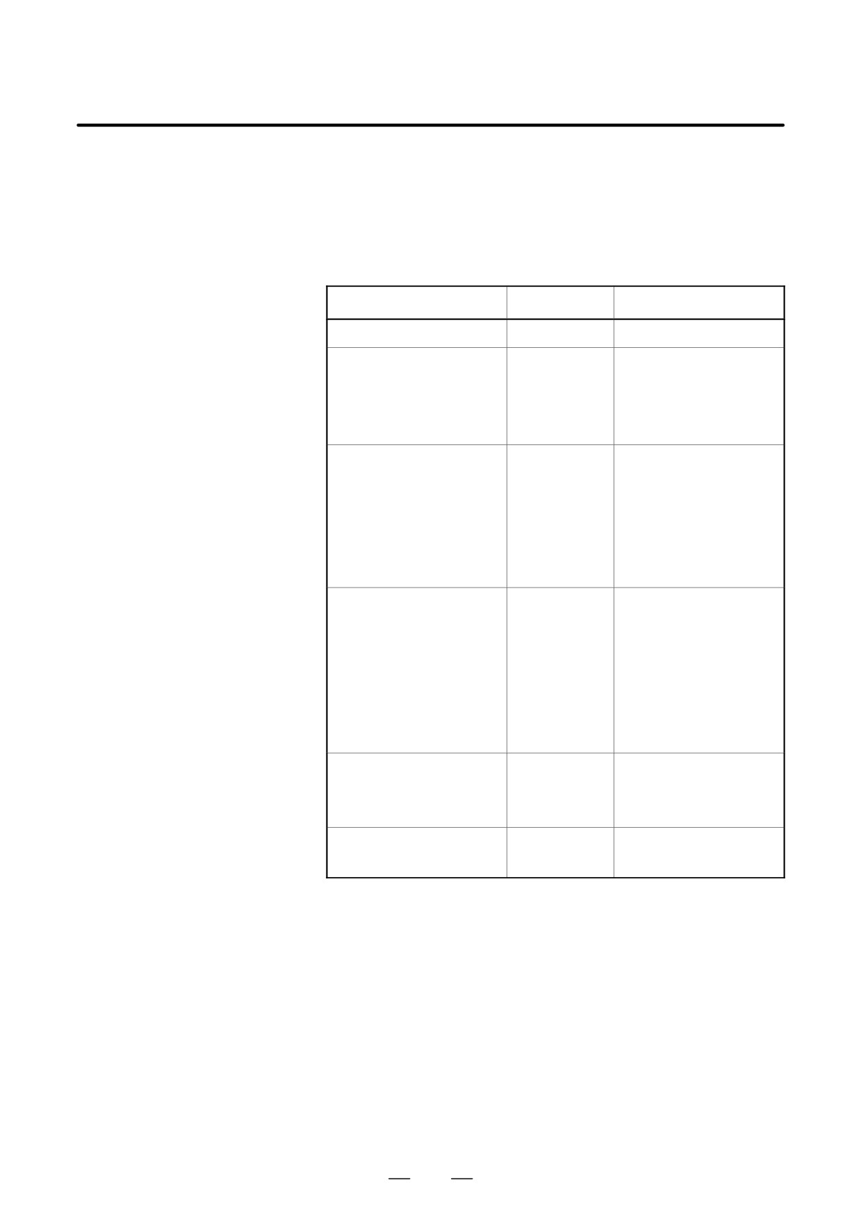
D Current position
Position information cannot be written but can be read.
Table 15.2 (j) System variables for position information
Variable
Position
Coordinate
Tool com-
Read
number
information
system
pensation
operation
value
during
movement
#5001-#5008
Block end point
Workpiece
Not
Enabled
coordinate
included
system
#5021-#5028
Current position
Machine
Included
Disabled
coordinate
system
#5041-#5048
Current position
Workpiece
coordinate
#5061-#5068
Skip signal position
system
Enabled
#5081, #5082
Tool offset value
Disabled
#5101-#5108
Deviated servo
position
D The first digit (from 1 to 8) represents an axis number.
D The tool offset value currently used for execution rather than the
immediately preceding tool offset value is held in variables #5081 to
5088.
D The tool position where the skip signal is turned on in a G31 (skip
function) block is held in variables #5061 to #5068. When the skip
signal is not turned on in a G31 block, the end point of the specified
block is held in these variables.
D When read during movement is “disabled,” this means that expected
values cannot be read due to the buffering (preread) function.
303

15. CUSTOM MACRO
PROGRAMMING
B-63524EN/01
D Workpiece coordinate
Workpiece zero point offset values can be read and written.
system compensation
Table 15.2 (k) System variables for workpiece zero point offset values
values (workpiece zero
point offset values)
Variable
Function
number
#5201
First-axis external workpiece zero point offset value
:
:
#5208
Eighth-axis external workpiece zero point offset value
#5221
First-axis G54 workpiece zero point offset value
:
:
#5228
Eighth-axis G54 workpiece zero point offset value
#5241
First-axis G55 workpiece zero point offset value
:
:
#5248
Eighth-axis G55 workpiece zero point offset value
#5261
First-axis G56 workpiece zero point offset value
:
:
#5268
Eighth-axis G56 workpiece zero point offset value
#5281
First-axis G57 workpiece zero point offset value
:
:
#5288
Eighth-axis G57 workpiece zero point offset value
#5301
First-axis G58 workpiece zero point offset value
:
:
#5308
Eighth-axis G58 workpiece zero point offset value
#5321
First-axis G59 workpiece zero point offset value
:
:
#5328
Eighth-axis G59 workpiece zero point offset value
NOTE
To use variables #5201 to #5328, the workpiece coordinate
system option is necessary.
304
B-63524EN/01
PROGRAMMING
15. CUSTOM MACRO
The operations listed in Table 15.3 (a) can be performed on variables. The
15.3
expression to the right of the operator can contain constants and/or
ARITHMETIC AND
variables combined by a function or operator. Variables #j and #K in an
LOGIC OPERATION
expression can be replaced with a constant. Variables on the left can also
be replaced with an expression.
Table 15.3 (a) Arithmetic and logic operation
Function
Format
Remarks
Definition
#i=#j
Sum
#i=#j+#k;
Difference
#i=#j-#k;
Product
#i=#j*#k;
Quotient
#i=#j/#k;
Sine
#i=SIN[#j];
An angle is specified in de-
grees. 90 degrees and 30
Arc sine
#i=ASIN[#j];
minutes is represented as
Cosine
#i=COS[#j];
90.5 degrees.
Arc cosine
#i=ACOS[#j];
Tangent
#i=TAN[#j];
Arctangent
#i=ATAN[#j]/[#k];
Square root
#i=SQRT[#j];
Absolute value
#i=ABS[#j];
Rounding off
#i=ROUND[#j];
Rounding down
#i=FIX[#j];
Rounding up
#i=FUP[#j];
Natural logarithm
#i=LN[#j]
Exponential function
#i=EXP[#j];
OR
#i=#j OR #k;
A logical operation is per-
formed on binary numbers
XOR
#i=#j XOR #k;
bit by bit.
AND
#i=#j AND #k;
Conversion from BCD to BIN
#i=BIN[#j];
Used for signal exchange
to and from the PMC
Conversion from BIN to BCD
#i=BCD[#j];
Explanations
D Angle units
The units of angles used with the SIN, COS, TAN, ASIN, ACOS and
ATAN functions are degrees. For example, 90 degrees and 30 minutes is
represented as 90.5 degrees.
D ARCSIN #i = ASIN[#j];
S The solution ranges are as indicated below:
When the NAT bit (bit 0 of parameter 6004) is set to 0: 270° to 90°
When the NAT bit (bit 0 of parameter 6004) is set to 1: -90° to 90°
S When #j is beyond the range of -1 to 1, P/S alarm No. 111 is issued.
S A constant can be used instead of the #j variable.
305
15. CUSTOM MACRO
PROGRAMMING
B-63524EN/01
D ARCCOS #i = ACOS[#j];
S The solution ranges from 180° to 0°.
S When #j is beyond the range of -1 to 1, P/S alarm No. 111 is issued.
S A constant can be used instead of the #j variable.
D ARCTAN
S Specify the lengths of two sides, separated by a slash (/).
#i = ATAN[#j]/[#k];
S The solution ranges are as follows:
When the NAT bit (bit 0 of parameter 6004) is set to 0: 0° to 360°
Example:
When #1 = ATAN[-1]/[-1]; is specified, #1 is 225.0
When the NAT bit (bit 0 of parameter 6004) is set to 1: -180° to
180°
Example:
When #1 = ATAN[-1]/[-1]; is specified, #1 is -135.0.
S A constant can be used instead of the #j variable.
D Natural logarithm
S Note that the relative error may become 10-8 or greater.
#i = LN[#j];
S When the antilogarithm (#j) is zero or smaller, P/S alarm No. 111 is
issued.
S A constant can be used instead of the #j variable.
D Exponential function
S Note that the relative error may become 10-8 or greater.
#i = EXP[#j];
S When the result of the operation exceeds 3.65
1047 (j is about 110),
an overflow occurs and P/S alarm No. 111 is issued.
S A constant can be used instead of the #j variable.
D ROUND function
S When the ROUND function is included in an arithmetic or logic
operation command, IF statement, or WHILE statement, the ROUND
function rounds off at the first decimal place.
Example:
When #1=ROUND[#2]; is executed where #2 holds 1.2345, the
value of variable #1 is 1.0.
S When the ROUND function is used in NC statement addresses, the
ROUND function rounds off the specified value according to the least
input increment of the address.
Example:
Creation of a drilling program that cuts according to the values
of variables #1 and #2, then returns to the original position
Suppose that the increment system is 1/1000 mm, variable #1
holds 1.2345, and variable #2 holds 2.3456. Then,
G00 G91 X-#1; Moves 1.235 mm.
G01 X-#2 F300; Moves 2.346 mm.
G00 X[#1+#2];
Since 1.2345 + 2.3456 = 3.5801, the travel distance is 3.580,
which does not return the tool to the original position.
This difference comes from whether addition is performed before
or after rounding off. G00X-[ROUND[#1]+ROUND[#2]] must be
specified to return the tool to the original position.
306

B-63524EN/01
PROGRAMMING
15. CUSTOM MACRO
D Rounding up and down
With CNC, when the absolute value of the integer produced by an
to an integer
operation on a number is greater than the absolute value of the original
number, such an operation is referred to as rounding up to an integer.
Conversely, when the absolute value of the integer produced by an
operation on a number is less than the absolute value of the original
number, such an operation is referred to as rounding down to an integer.
Be particularly careful when handling negative numbers.
Example:
Suppose that #1=1.2 and #2=-1.2.
When #3=FUP[#1] is executed, 2.0 is assigned to #3.
When #3=FIX[#1] is executed, 1.0 is assigned to #3.
When #3=FUP[#2] is executed, -2.0 is assigned to #3.
When #3=FIX[#2] is executed, -1.0 is assigned to #3.
D Abbreviations of
When a function is specified in a program, the first two characters of the
arithmetic and logic
function name can be used to specify the function. (See III-9.7)
operation commands
Example:
ROUND → RO
FIX → FI
D Priority of operations
(1) Functions
(2) Operations such as multiplication and division (*, /, AND, MOD)
(3) Operations such as addition and subtraction (+, -, OR, XOR)
Example) #1=#2+#3*SIN[#4];
(1)
(2)
(3)
(1), (2), and (3) indicate the order of operations.
D Bracket nesting
Brackets are used to change the order of operations. Brackets can be used
to a depth of five levels including the brackets used to enclose a function.
When a depth of five levels is exceeded, alarm No. 118 occurs.
Example) #1=SIN [ [ [#2+#3] *#4 +#5] *#6] ;
(1)
(2)
(3)
(4)
(5)
(1) to (5) indicate the order of operations.
Limitations
D Brackets
Brackets ([, ]) are used to enclose an expression. Note that parentheses
are used for comments.
307
15. CUSTOM MACRO
PROGRAMMING
B-63524EN/01
D Operation error
Errors may occur when operations are performed.
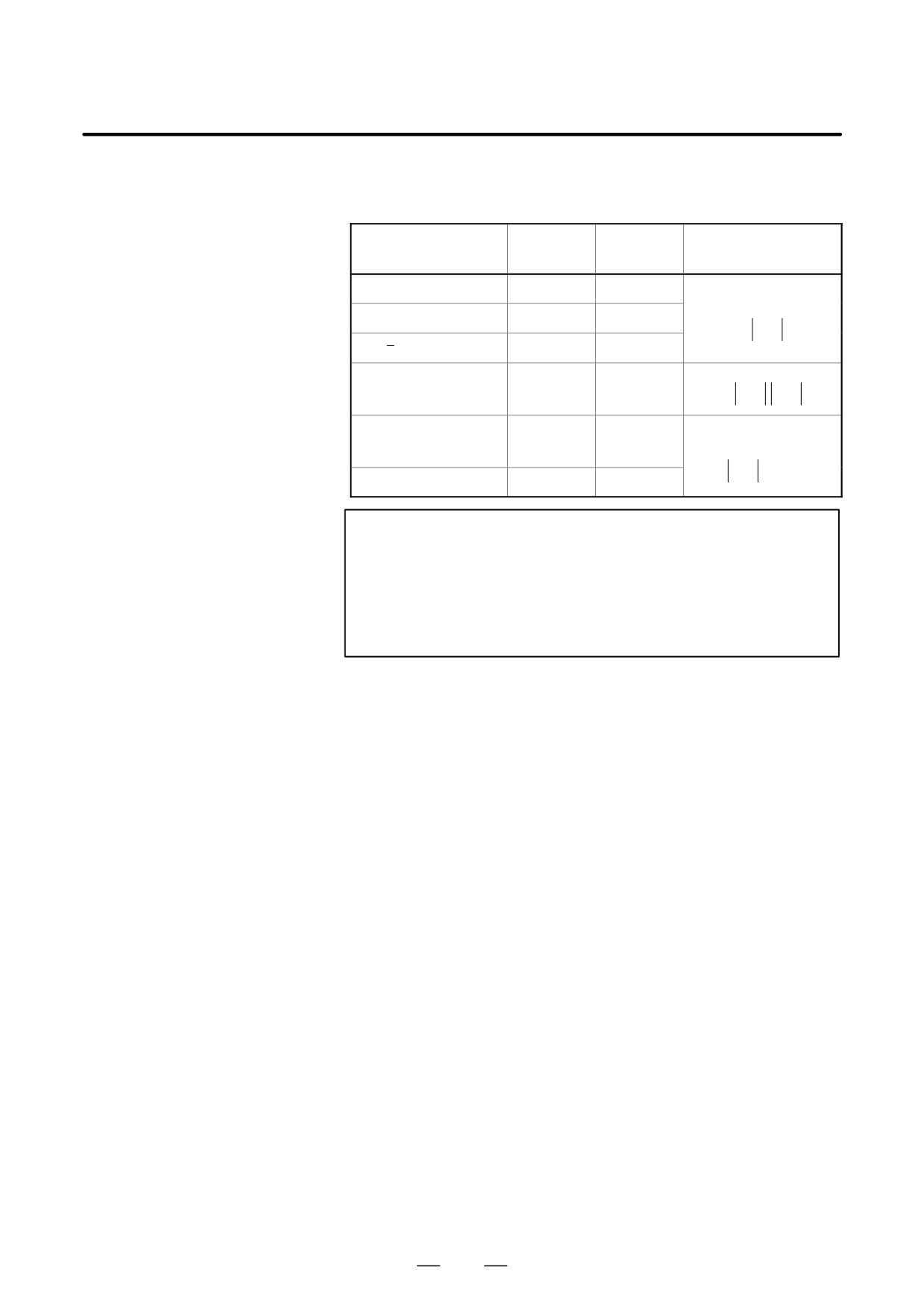
Table 15.3 (b) Errors involved in operations
Operation
Average
Maximum
Type of error
error
error
a = b*c
1.55×10⁻¹⁰
4.66×10⁻¹⁰
Relative error(*1)
a = b / c
4.66×10⁻¹⁰
1.88×10⁻⁹
ε
b
Ǹ
1.24×10⁻⁹
3.73×10⁻⁹
a+ b
(*2)
a = b + c
2.33×10⁻¹⁰
5.32×10⁻¹⁰
ε
ε
Min
a = b - c
b
c
a = SIN [ b ]
5.0×10⁻⁹
1.0×10⁻⁸
Absolute error(*3)
a = COS [ b ]
ε
degrees
a = ATAN [ b ] / [ c ]
(*4)
1.8×10⁻⁶
3.6×10⁻⁶
NOTE
1
The relative error depends on the result of the operation.
2
Smaller of the two types of errors is used.
3
The absolute error is constant, regardless of the result of the
operation.
4
Function TAN performs SIN/COS.
S The precision of variable values is about 8 decimal digits. When very
large numbers are handled in an addition or subtraction, the expected
results may not be obtained.
Example:
When an attempt is made to assign the following values to
variables #1 and #2:
#1=9876543210123.456
#2=9876543277777.777
the values of the variables become:
#1=9876543200000.000
#2=9876543300000.000
In this case, when #3=#2-#1; is calculated, #3=100000.000 results.
(The actual result of this calculation is slightly different because
it is performed in binary.)
S Also be aware of errors that can result from conditional expressions
using EQ, NE, GE, GT, LE, and LT.
Example:
IF [#1 EQ #2] is effected by errors in both #1 and #2, possibly
resulting in an incorrect decision.
Therefore, instead find the difference between the two variables
with IF[ABS[#1-#2]LT0.001].
Then, assume that the values of the two variables are equal when
the difference does not exceed an allowable limit (0.001 in this
case).
308