FANUC MANUAL GUIDE i. OPERATOR’S MANUAL - page 22
3.PROCESS LIST EDITING FUNCTION MULTI-PATH LATHE FUNCTIONS
B-63874EN/04
z Others
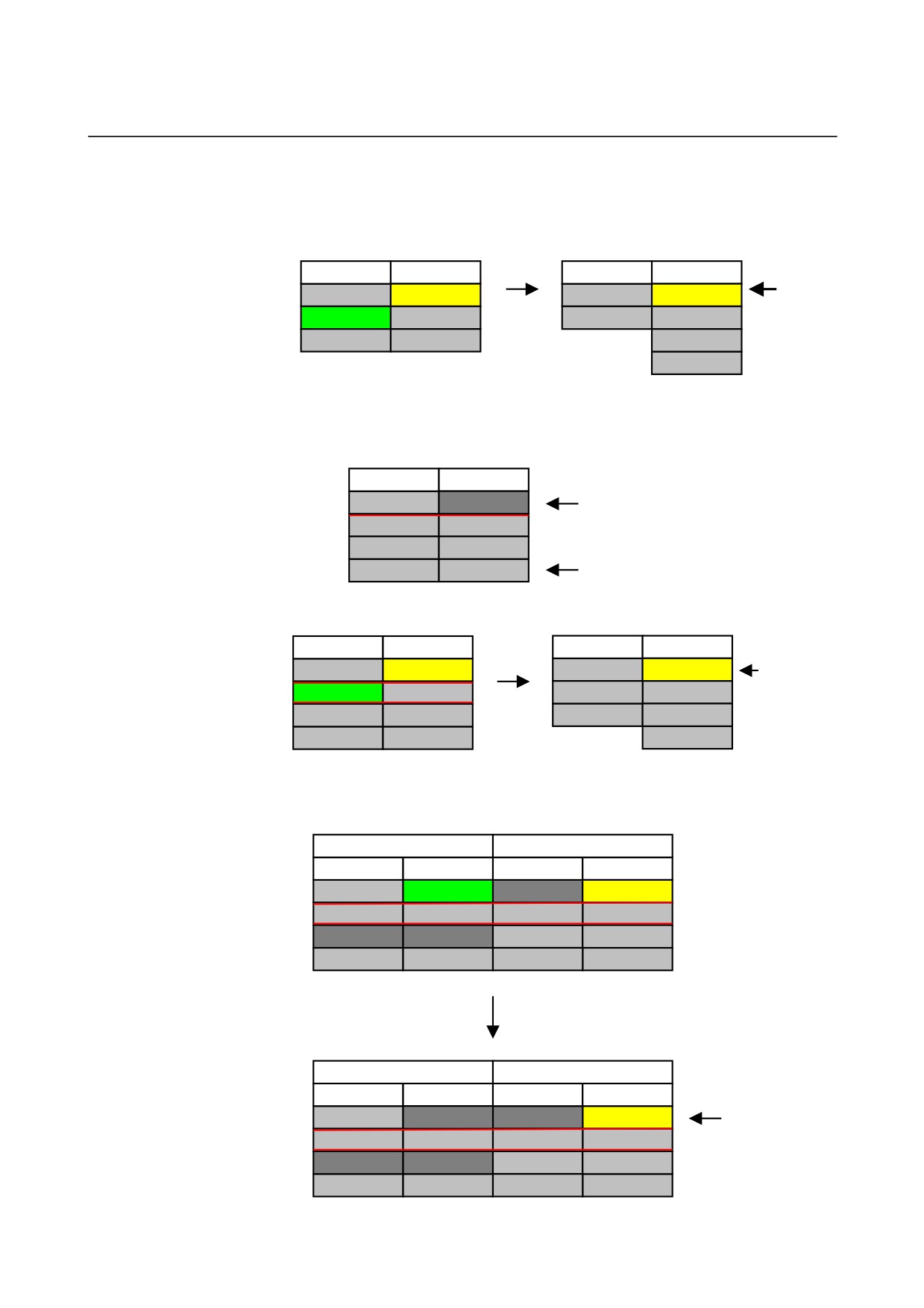
• When the destination process is not vacant, it is possible to
select overwrite, insert, and cancel.
TURRET 1
TURRET 2
TURRET 1
TURRET 2
Insert
N10 ROUGH
N10 DRILL
N10 ROUGH
FINE
&
*N20 FINE
N20 TAP
Select
%
N10 DRILL
move
%
%
Insert
N20 TAP
%
• There is the cell that cannot be specified as source and
destination.
TURRET 1
TURRET 2
N10 ROUGH
Input impropriety cell
N20 MIDDLE
N10 DRILL
N30 FINE
N20 TAP
%
%
% cell
• The waiting and transfer will not be moved.
TURRET 1
TURRET 2
TURRET 1
TURRET 2
N10 ROUGH
N10 DRILL
N10 ROUGH
N10 TRANS
Transfer
will not
*N20 TRANS
N20 TRANS
N30 FINE
N20 TRANS
be
N30 FINE
N30 TAP
Move
%
N30 TAP
moved.
%
%
%
• It is possible to move to input impropriety cell just in case
between the same line and turret.
SPINDLE 1
SPINDLE 2
TURRET 1
TURRET 2
TURRET 1
TURRET 2
N10 ROUGH
*N10 DRILL
N20 TRANS
N20 TRANS
N30 FINE
N30 TAP
%
%
%
%
Move
SPINDLE 1
SPINDLE 2
TURRET 1
TURRET 2
TURRET 1
TURRET 2
N10 ROUGH
N10 DRILL
Moving to
input
N20 TRANS
N20 TRANS
impropriety
N30 FINE
N30 TAP
cell is
%
%
%
%
done.
- 612 -
B-63874EN/04
MULTI-PATH LATHE FUNCTIONS 3.PROCESS LIST EDITING FUNCTION
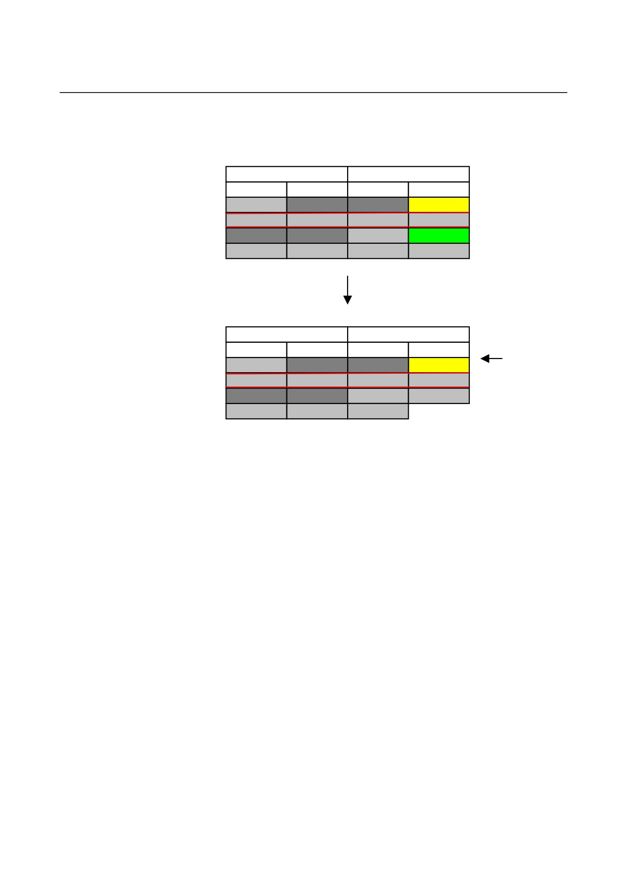
• It is possible to move to input impropriety cell just in case that
any cell in the same line and turret is input impropriety one.
SPINDLE 1
SPINDLE 2
TURRET 1
TURRET 2
TURRET 1
TURRET 2
N10 ROUGH
CAN’T
CAN’T
N20 TRANS
N20 TRANS
N30 FINE
*N30 TAP
%
%
%
%
Moving
SPINDLE 1
SPINDLE 2
TURRET 1
TURRET 2
TURRET 1
TURRET 2
Moving to
N10 ROUGH
N30 TAP
input
N20 TRANS
N20 TRANS
impropriety
N30 FINE
%
cell is done.
%
%
%
- 613 -
3.PROCESS LIST EDITING FUNCTION MULTI-PATH LATHE FUNCTIONS
B-63874EN/04
3.5.5
Modification of Process Name
z Function
• Modify the process name.
• In NC program,
Start process block : G1992 Sx (xxxx)
Modify comment in that block.
When clear the process name, delete comment with a round
bracket.
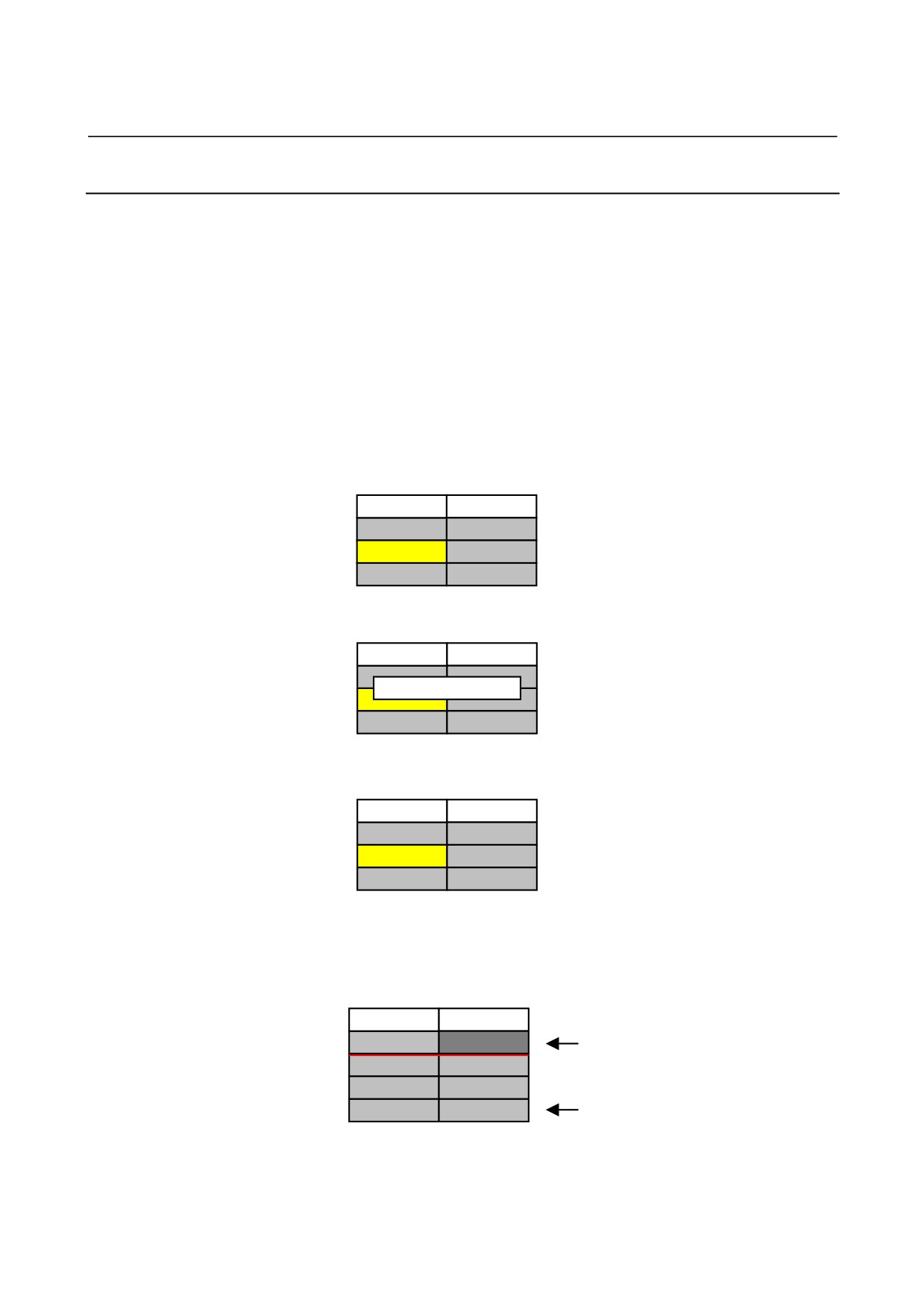
z Basic Operation
1. Move the cursor to the cell to be modified.
TURRET 1
TURRET 2
N10 ROUGH
N10 DRILL
N20 FINE
N20 TAP
%
%
2. Press [RENAME].
TURRET 1
TURRET 2
N10 ROUGH
N10 DRILL
The dialog for the process name input
PROC NAME MIDDLE
is displayed. Input MIDDLE as an
N
example.
%
%
3. Press OK, and the process name will be modified.
TURRET 1
TURRET 2
N10 ROUGH
N10 DRILL
N20 MIDDLE
N20 TAP
(When cancel is pressed, return to
previous state.)
%
%
z Others
• There is some cell whose name cannot be modified.
TURRET 1
TURRET 2
N10 ROUGH
Input impropriety cell
N20 MIDDLE
N10 DRILL
N30 FINE
N20 TAP
%
%
% cell
- 614 -
B-63874EN/04
MULTI-PATH LATHE FUNCTIONS 3.PROCESS LIST EDITING FUNCTION
3.5.6
Program Edit
z
Function
• Edit the process.
• The NC Program with current cell is opened in all screen mode,
and the cursor is set to the head of the process with current cell.
z
Basic Operation
1. Move the cursor to the cell to be edited.
TURRET 1
TURRET 2
N10 ROUGH
N10 DRILL
N20 FINE
N20 TAP
%
%
2. Press [EDTPRG].
;
N10 G1992 S1 (ROUGH);
The cursor of the edit screen
:
automatically moves to the start
:
position of the process.
G1993;
;
3. Do the edit work.
;
N10 G1992 S1 (ROUGH);
The Edit work is done with usual
:
edit screen. (all screen display by
G1993;
the size substitution)
N20 G1992 S1 (FINE);
:
G00X0.Z0.;
The following process can be
:
similarly edited because of a usual
G1993;
edit screen.
4. Press [EDWORK].
TURRET 1
TURRET 2
N10 ROUGH
N10 DRILL
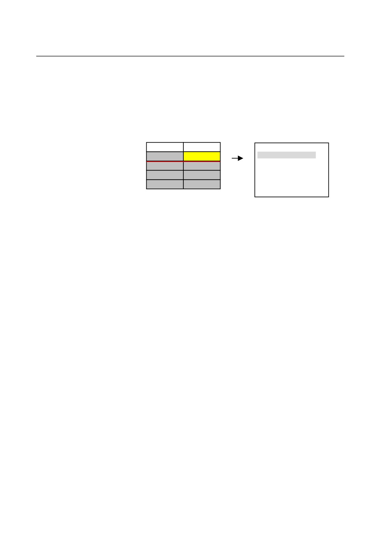
The process edited on a usual edit screen
N20 FINE
N20 TAP
becomes a current cell.
%
%
- 615 -
3.PROCESS LIST EDITING FUNCTION MULTI-PATH LATHE FUNCTIONS
B-63874EN/04
z Others
• When select head of MANUAL GUIDE i according to tool post
selection signal, it is necessary to set tool post selection signal
to the head that the target cell belongs to in advance.
• When edit work is started on the input impropriety cell, the
next effective process in the same turret will be opened.
TURRET 1
TURRET 2
;
N10 ROUGH
CAN’T EDIT
N10 G1992 S1 (DRILL);
:
N20 MIDDLE
N10 DRILL
EDTPRG
:
N30 FINE
N20 TAP
G1993;
%
%
;
- 616 -
B-63874EN/04
MULTI-PATH LATHE FUNCTIONS 3.PROCESS LIST EDITING FUNCTION
3.5.7
Assign of Waiting
z Function
• Set the waiting between the process.
• In NC program,
Start process block : G1992 Sx (xxxx)
End process block : G1993
Mxxx (Pxx) will be set to one or both of these blocks.
z Basic Operation
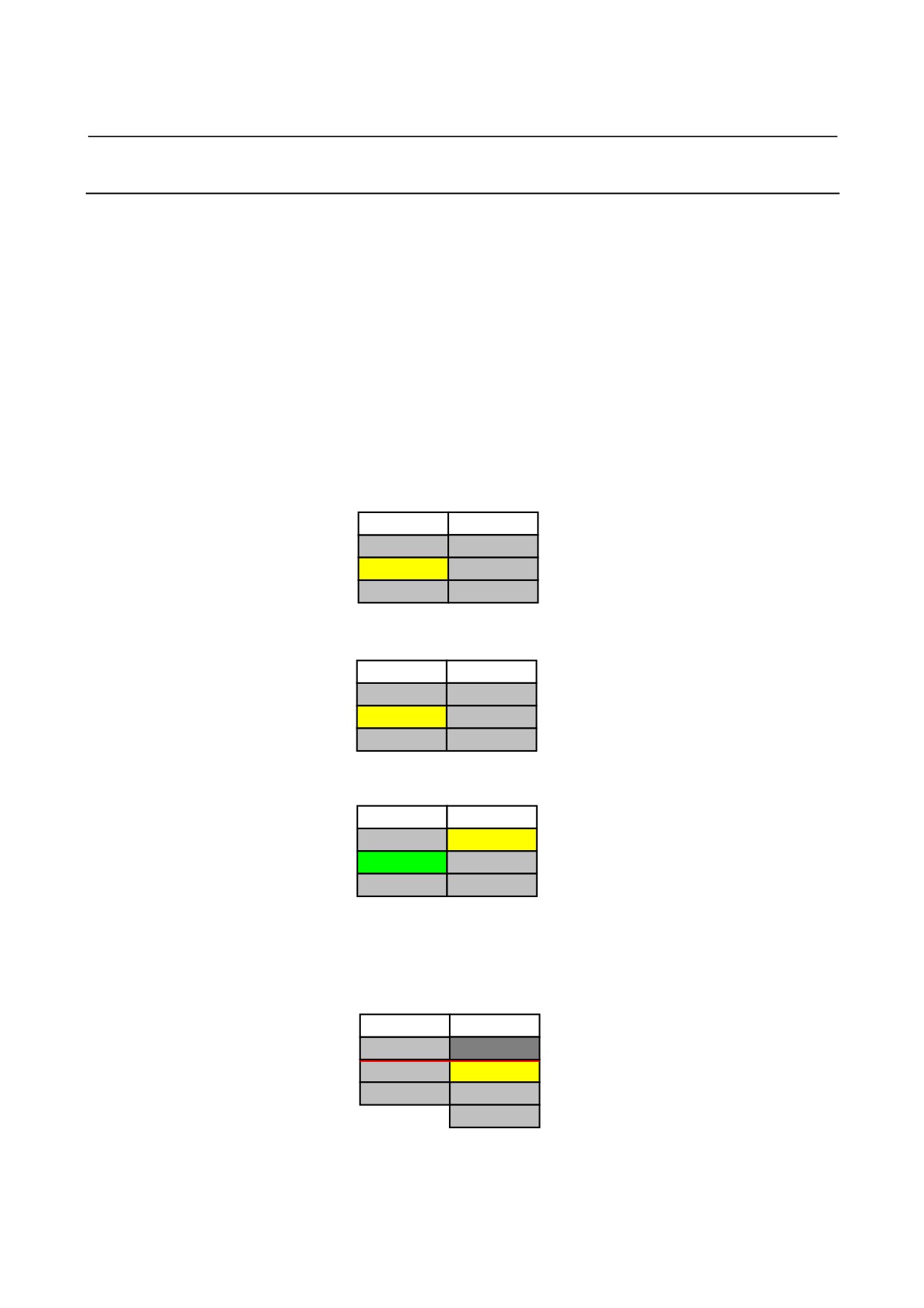
1. Press [STWAIT]. (Cursor position pretermission)
TURRET 1
TURRET 2
N10 ROUGH
N10 DRILL
N20 FINE
N20 TAP
The software key array changes into
set waiting mode.
%
%
2. Move cursor to the source waiting, and press [SELECT].
TURRET 1
TURRET 2
N10 ROUGH
N10 DRILL
*N20 FINE
N20 TAP
Add “*” to the top of the selected cell.
%
%
3. Move cursor to the destination waiting, and press [SELECT].
TURRET 1
TURRET 2
Moreover background color of the
N10 ROUGH
*N10 DRILL
source-waiting cell become green.
*N20 FINE
N20 TAP
%
%
Press any one of [SETTOP], [SETEND],
and [STBOTH].
4. Press [SET-].
• When [SETTOP] is pressed
TURRET 1
TURRET 2
(When finished normally, selected state will
N10 ROUGH
be released automatically.)
N20 FINE
N10 DRILL
%
N20 TAP
%
- 617 -
3.PROCESS LIST EDITING FUNCTION MULTI-PATH LATHE FUNCTIONS
B-63874EN/04
• When [SETEND] is pressed
TURRET 1
TURRET 2
N10 ROUGH
N10 DRILL
(When finished normally, selected state will
be released automatically.)
N20 FINE
%
N20 TAP
%
• When [STBOTH] is pressed
TURRET 1
TURRET 2
N10 ROUGH
(When finished normally, selected state will
N20 FINE
N10 DRILL
be released automatically.)
%
N20 TAP
%
5. Press [RETURN], and release set waiting mode.
z Others
• There is some cell that cannot be specified as source and
destination waiting.
TURRET 1
TURRET 2
N10 ROUGH
Input impropriety cell
N20 MIDDLE
N10 DRILL
N30 FINE
N20 TAP
%
%
% cell
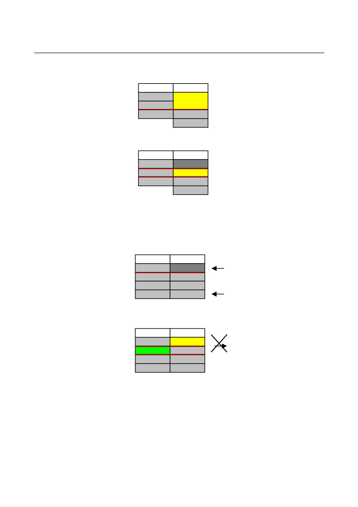
• When the waiting has already been set, the waiting cannot be
set.
TURRET 1
TURRET 2
N10 ROUGH
*N10 DRILL
*N20 WAIT
N20 WAIT
N30 FINE
N30 TAP
Waiting
Operation
%
%
• In case of shortage of waiting M code, the waiting cannot be
set.
• It is possible to set the waiting just between upper parts or
lower parts.
- 618 -
B-63874EN/04
MULTI-PATH LATHE FUNCTIONS 3.PROCESS LIST EDITING FUNCTION
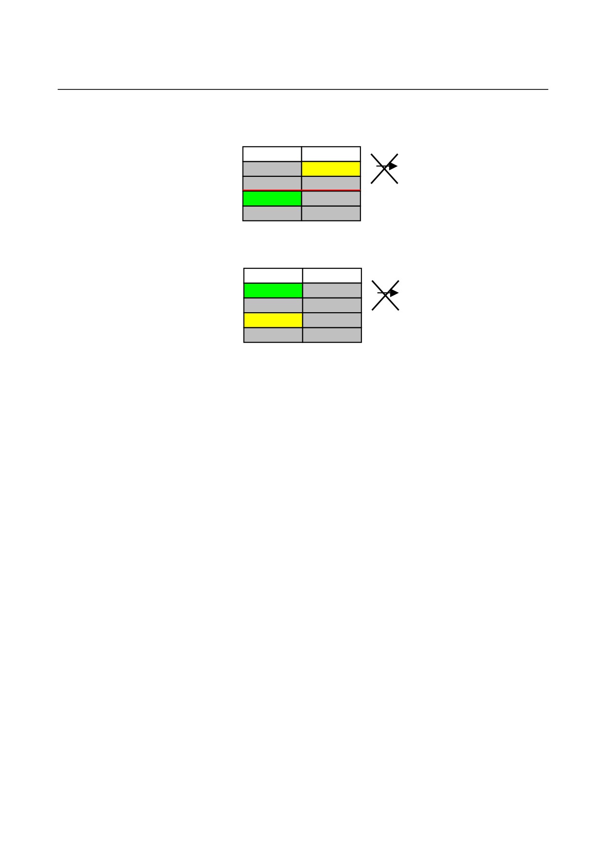
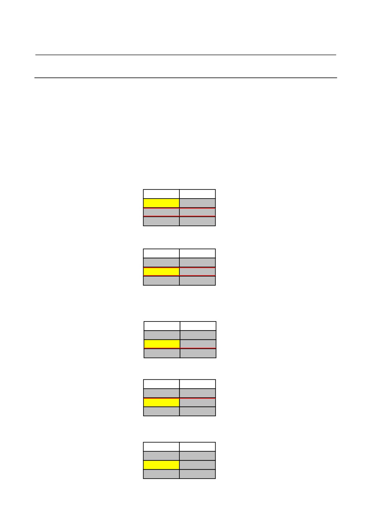
• It is impossible to set waiting across other waiting.
TURRET 1
TURRET 2
N10 ROUGH
*N10 DRILL
N20 TRANS
N20 TRANS
*N30 FINE
N30 TAP
Waiting
%
%
Operation
• It is impossible to set waiting between the process in the same
path.
TURRET 1
TURRET 2
*N10 ROUGH
N10 DRILL
N20 TRANS
N20 TRANS
*N30 FINE
N30 TAP
Waiting
%
%
Operation
- 619 -
3.PROCESS LIST EDITING FUNCTION MULTI-PATH LATHE FUNCTIONS
B-63874EN/04
3.5.8
Release of Waiting
z Function
• Release the waiting between the process.
• In NC program,
Start process block : G1992 Sx (xxxx)
End process block : G1993
Mxxx (Pxx) will be deleted from one or both of these blocks.
z Basic Operation
1. Press [CLWAIT]. (Cursor position pretermission)
TURRET 1
TURRET 2
N10 ROUGH
N10 DRILL
The software key array changes into
release waiting mode.
N20 FINE
N20 TAP
%
%
2. Move cursor to the cell that have waiting.
TURRET 1
TURRET 2
N10 ROUGH
N10 DRILL
N20 FINE
N20 TAP
Press any one of [CLTOP], [CLEND],
and [CLBOTH].
%
%
3. Press [CL-].
• When [CLTOP] is pressed
TURRET 1
TURRET 2
N10 ROUGH
N10 DRILL
(The opposite waiting will also be
N20 FINE
N20 TAP
released.)
%
%
• When [CLEND] is pressed
TURRET 1
TURRET 2
N10 ROUGH
N10 DRILL
N20 FINE
N20 TAP
(The opposite waiting will also be
%
%
released.)
• When [CLBOTH] is pressed
TURRET 1
TURRET 2
N10 ROUGH
N10 DRILL
(The opposite waiting will also be
N20 FINE
N20 TAP
released.)
%
%
- 620 -
B-63874EN/04
MULTI-PATH LATHE FUNCTIONS 3.PROCESS LIST EDITING FUNCTION
4. Press [RETURN], and release waiting mode.
z Others
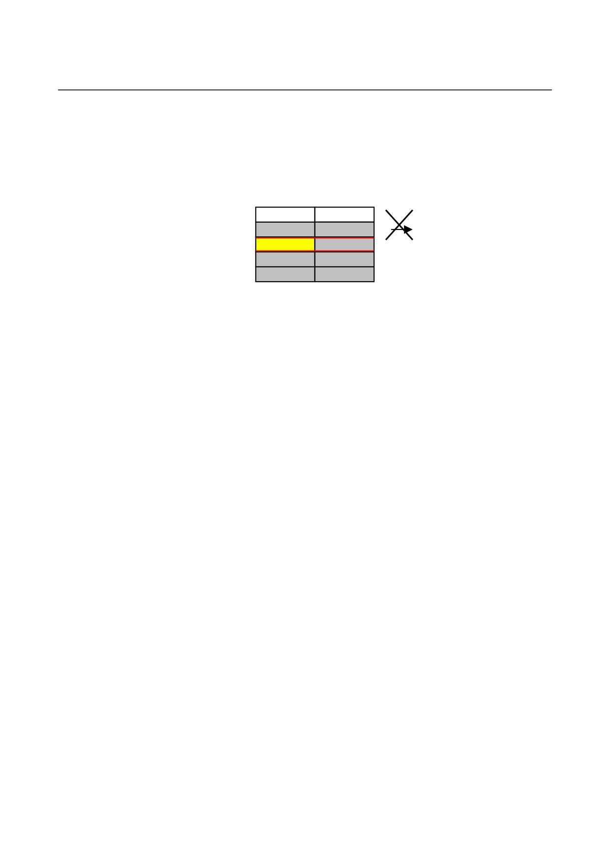
• The transfer cannot be operated by release waiting.
TURRET 1
TURRET 2
N10 ROUGH
N10 DRILL
N20 TRANS
N20 TRANS
Release
N30 FINE
N30 TAP
Waiting
%
%
Operation
- 621 -
3.PROCESS LIST EDITING FUNCTION MULTI-PATH LATHE FUNCTIONS
B-63874EN/04
3.5.9
Assign of Transfer
z Function
• Set the transfer between the process.
• In NC program,
Start process block : G1992 Sx (xxxx)
Q0 Mxxx (Pxx) will be set to above block,
End process block : G1993
Mxxx (Pxx) will be set to above block.
z Basic Operation
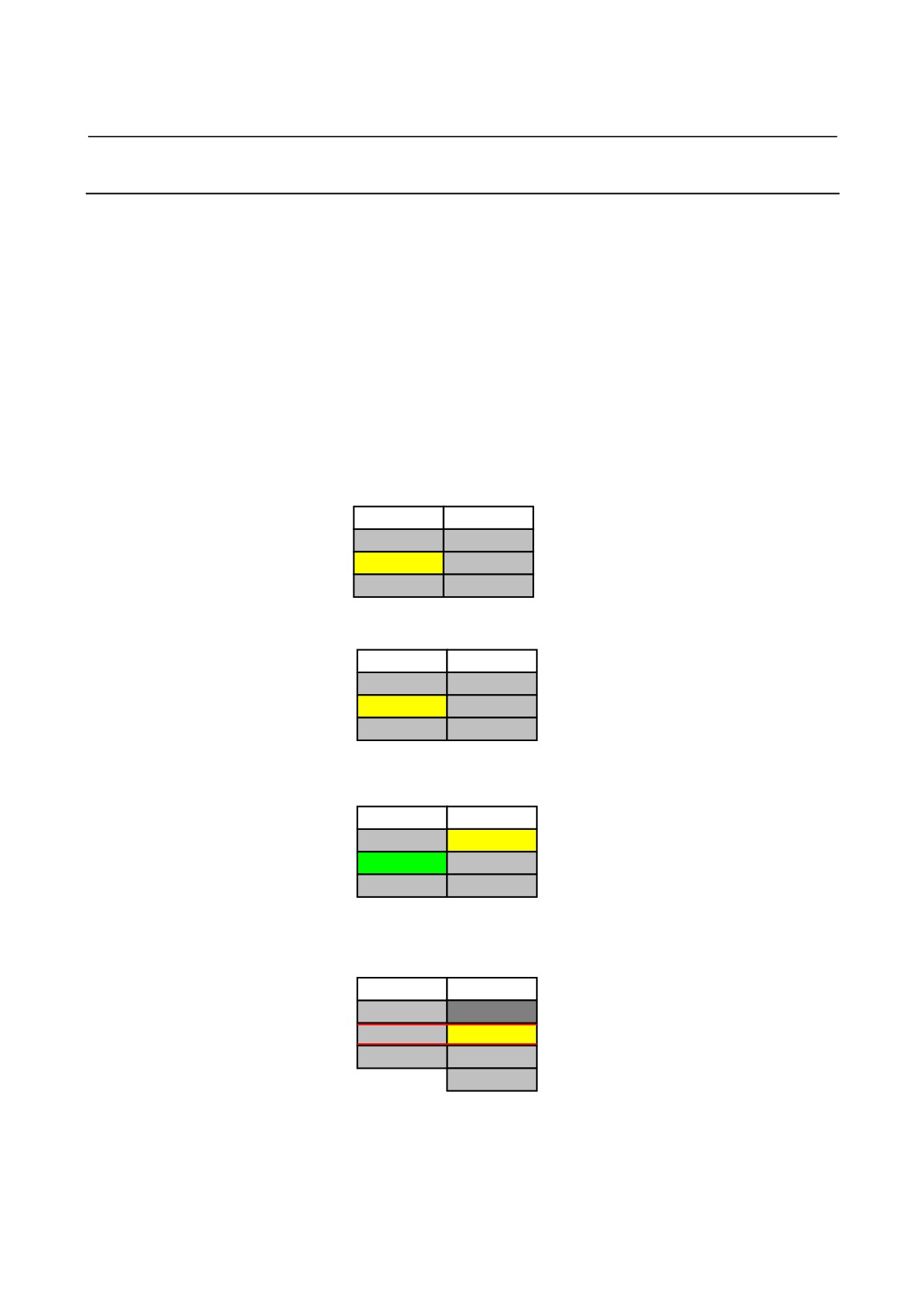
1. Press [STTRNS]. (Cursor position pretermission)
TURRET 1
TURRET 2
N10 ROUGH
N10 DRILL
The software key array changes into
N20 FINE
N20 TAP
set waiting mode.
%
%
2. Move cursor to the source transfer, and press [SELECT].
TURRET 1
TURRET 2
N10 ROUGH
N10 DRILL
*N20 FINE
N20 TAP
Add “*” to the top of the selected
cell.
%
%
3. Move cursor to the destination transfer, and press [SELECT].
Add “*” to the top of the selected
TURRET 1
TURRET 2
cell.
N10 ROUGH
*N10 DRILL
Moreover background color of the
*N20 FINE
N20 TAP
source waiting cell become green.
%
%
Press either [STTRNS] or
[CANCEL].
4. Press [STTRNS].
TURRET 1
TURRET 2
N10 ROUGH
(When finished normally, selected state will
N20 FINE
N10 DRILL
be released automatically.)
%
N20 TAP
%
5. Press [RETURN], and release set transfer mode.
- 622 -
B-63874EN/04
MULTI-PATH LATHE FUNCTIONS 3.PROCESS LIST EDITING FUNCTION
z Others
• There is some cell that cannot be specified as source and
destination transfer.
TURRET 1
TURRET 2
N10 ROUGH
Input impropriety cell
N20 MIDDLE
N10 DRILL
N30 FINE
N20 TAP
%
%
% cell
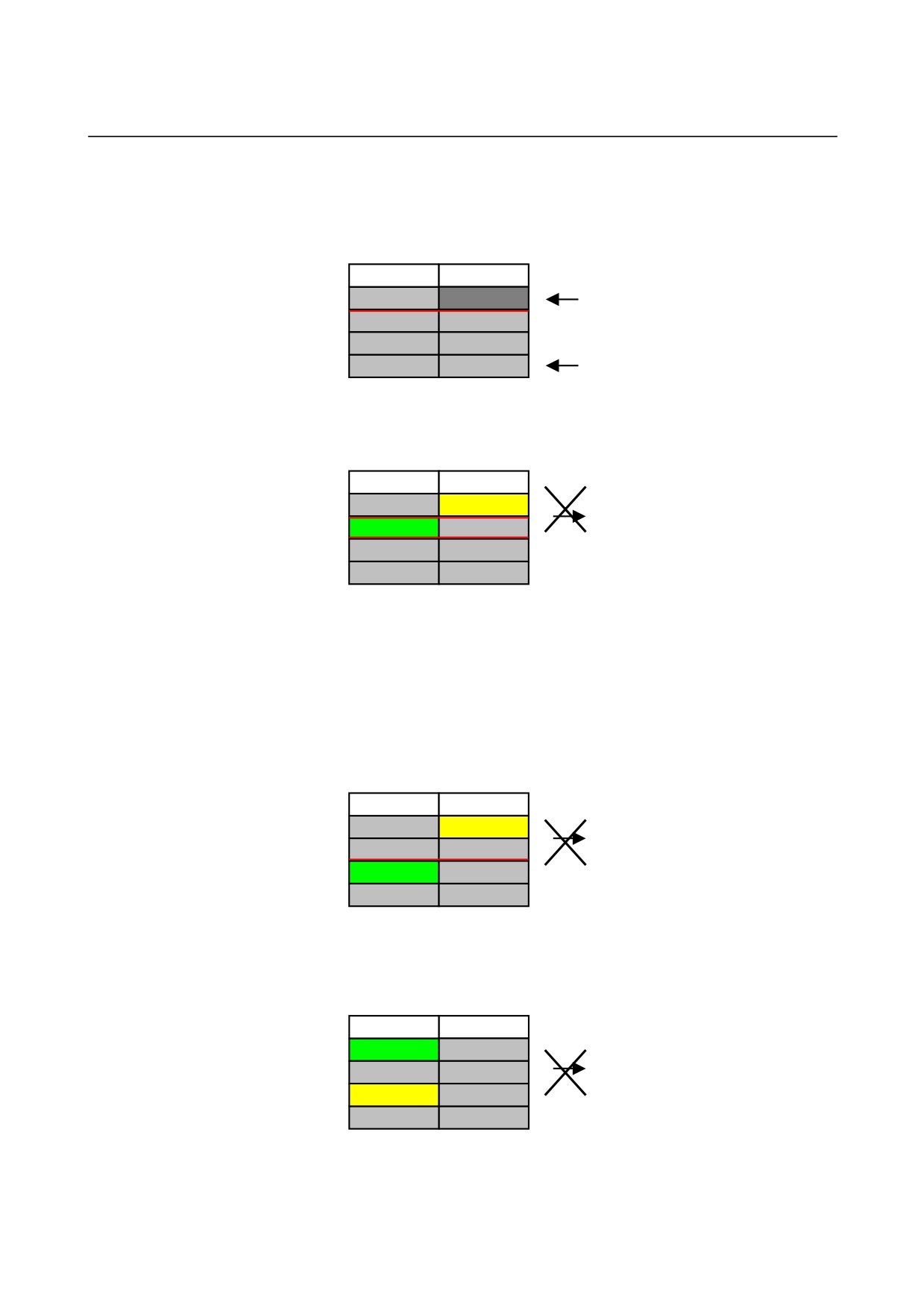
• When the waiting or transfer has already been set, the transfer
cannot be set.
TURRET 1
TURRET 2
N10 ROUGH
*N10 DRILL
*N20 WAIT
N20 WAIT
N30 FINE
N30 TAP
Transfer
Operation
%
%
• In case of shortage of waiting M code, the waiting cannot be
set.
• It is possible to set the transfer just between the cells that have
no waiting.
• It is impossible to set waiting across other waiting and transfer.
TURRET 1
TURRET 2
N10 ROUGH
*N10 DRILL
N20 TRANS
N20 TRANS
*N30 FINE
N30 TAP
%
%
Waiting
Operation
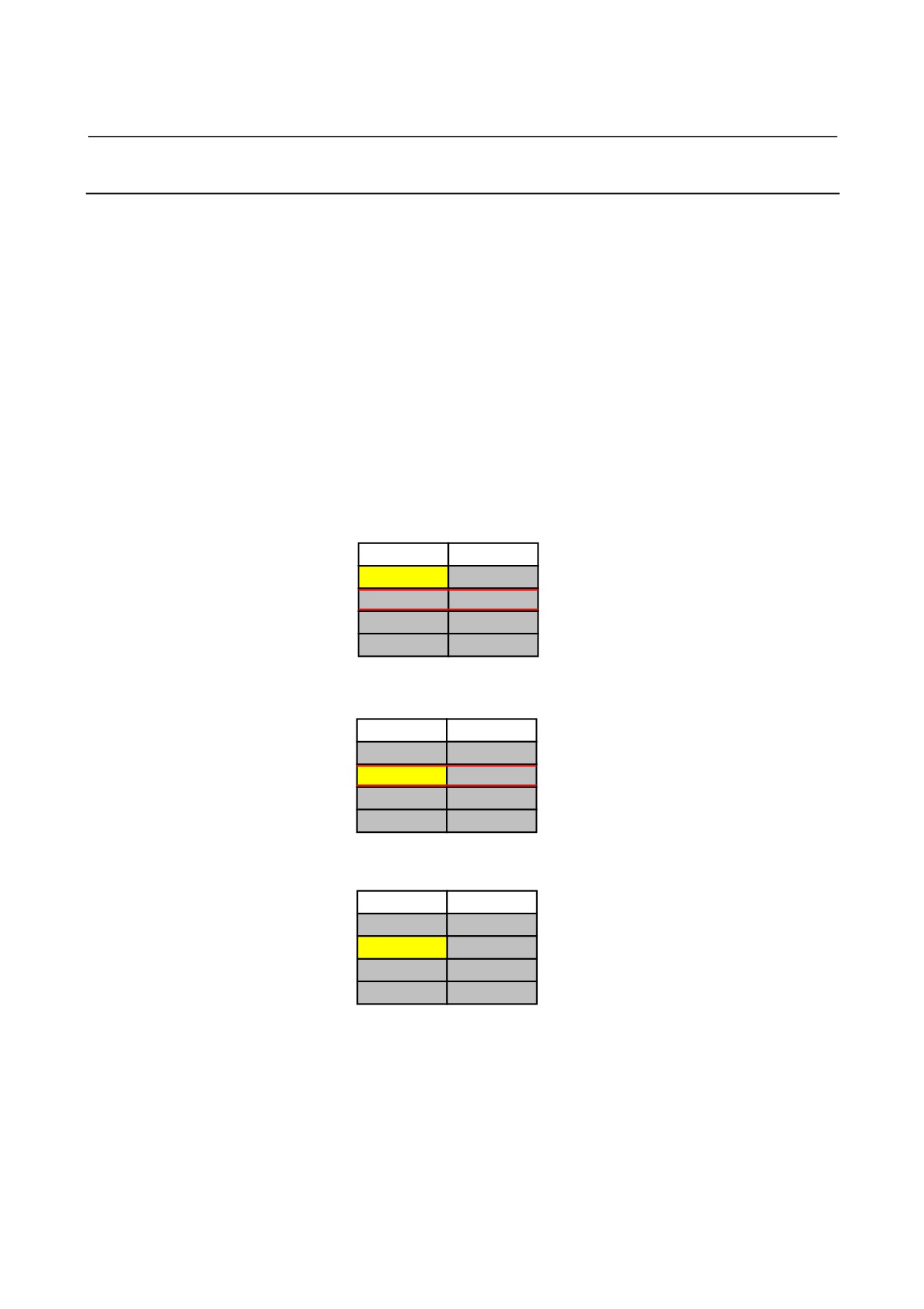
• It is impossible to set transfer between the process in the same
path.
TURRET 1
TURRET 2
*N10 ROUGH
N10 DRILL
N20 TRANS
N20 TRANS
*N30 FINE
N30 TAP
Transfer
%
%
Operation
- 623 -
3.PROCESS LIST EDITING FUNCTION MULTI-PATH LATHE FUNCTIONS
B-63874EN/04
3.5.10 Release Transfer
z Function
• Release the transfer between the process.
• In NC program,
Start process block : G1992 Sx (xxxx)
Q0 Mxxx (Pxx) will be deleted from above block.
End process block : G1993
Mxxx (Pxx) will be deleted from above block.
z Basic Operation
1. Press [CLTRNS]. (Cursor position pretermission)
TURRET 1
TURRET 2
N10 ROUGH
N10 DRILL
N20 TRANS
N20 TRANS
The software key array changes into
N30 FINE
N30 TAP
release transfer mode.
%
%
2. Move cursor to the cell that have transfer.
TURRET 1
TURRET 2
N10 ROUGH
N10 DRILL
N20 TRANS
N20 TRANS
Press either [CLTRNS] or [CANCEL].
N30 FINE
N30 TAP
%
%
3. Press [CLTRANS].
TURRET 1
TURRET 2
N10 ROUGH
N10 DRILL
N20 TRANS
N20 TRANS
N30 FINE
N30 TAP
(The opposite transfer will also be
released.)
%
%
4. Press [RETURN], and release transfer mode.
- 624 -
B-63874EN/04
MULTI-PATH LATHE FUNCTIONS 3.PROCESS LIST EDITING FUNCTION
z Others
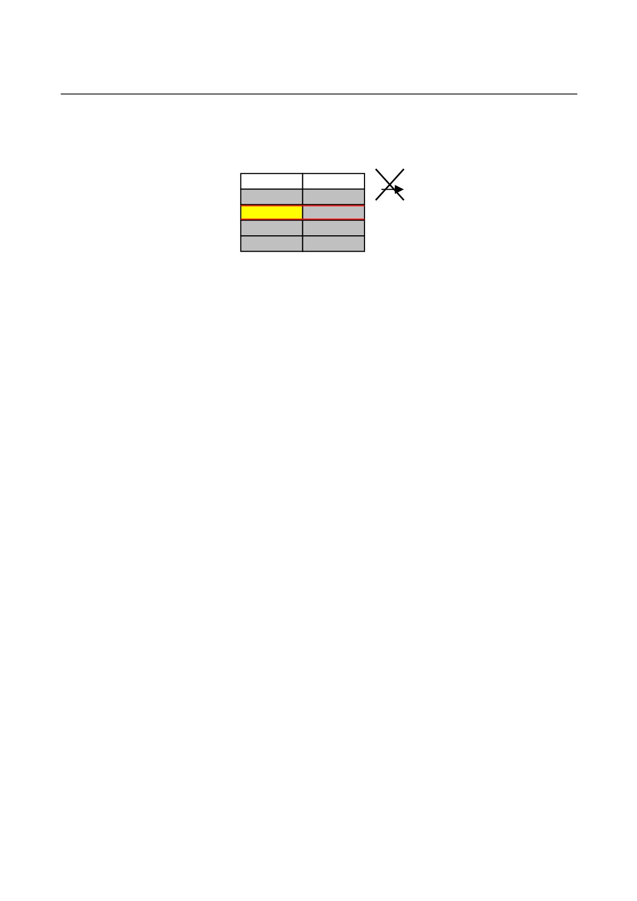
• The waiting cannot be operated by release transfer.
TURRET 1
TURRET 2
N10 ROUGH
N10 DRILL
N20 TRANS
N20 TRANS
Release
Transfer
N30 FINE
N30 TAP
Operation
%
%
- 625 -
3.PROCESS LIST EDITING FUNCTION MULTI-PATH LATHE FUNCTIONS
B-63874EN/04
3.5.11 Addition of Optional Block Skip for Each Path Program
Check
z Function
• In NC program,
Start process block : G1992 Sx (xxxx)
End process block : G1993
Add any one of
“/7”, “/8”, and “9” to the top of each block
between above two blocks.
/7 : process belong to spindle-1. (except transfer process)
/8 : process belong to spindle-2. (except transfer process)
/9 : transfer process
z Basic Operation
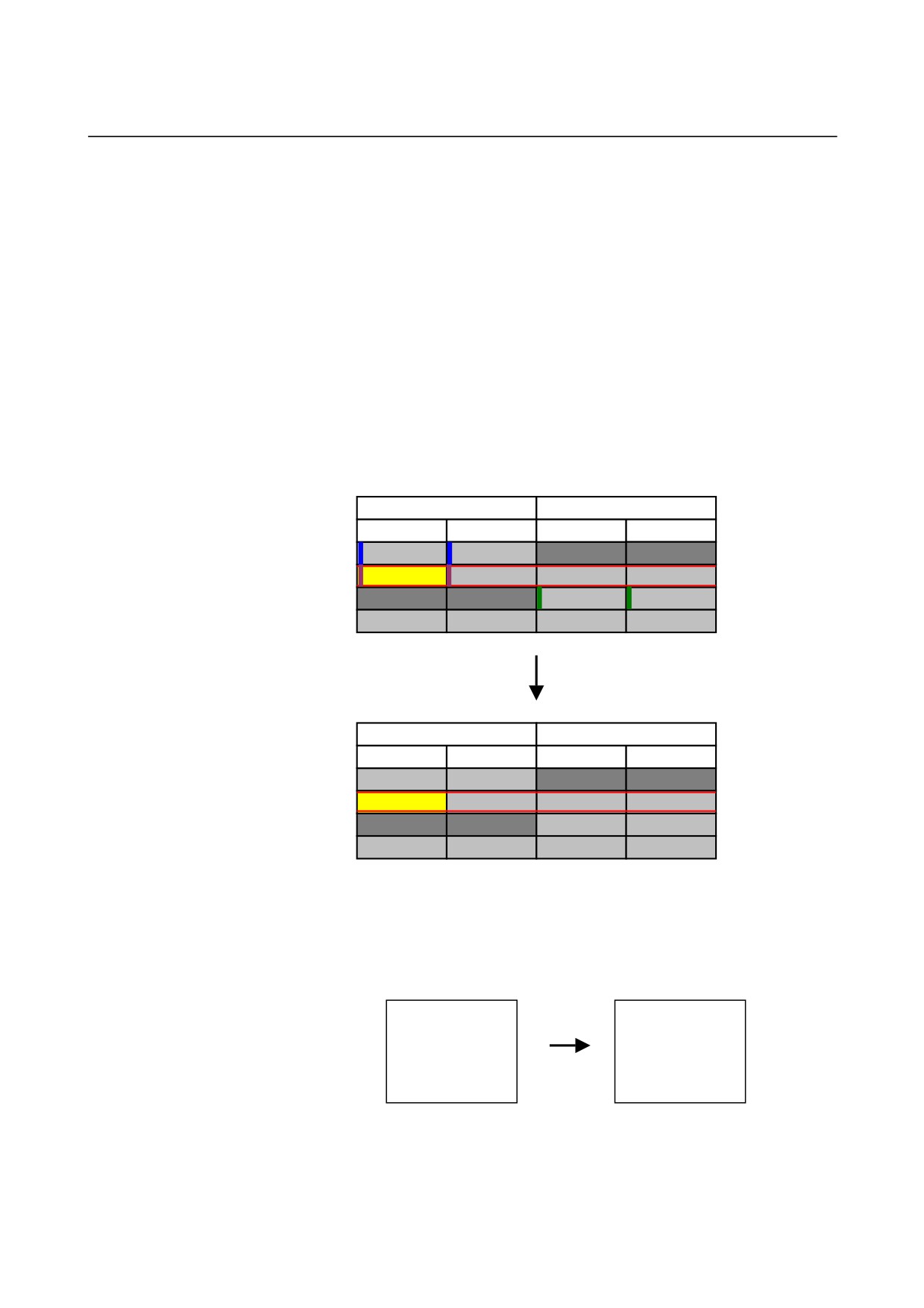
Press [ADD /].
SPINDLE 1
SPINDLE 2
TURRET 1
TURRET 2
TURRET 1
TURRET 2
N10 ROUGH
N10 DRILL
N20 TRANS
N20 TRANS
N30 FINE
N30 TAP
%
%
%
%
Adding of optional block skip
SPINDLE 1
SPINDLE 2
TURRET 1
TURRET 2
TURRET 1
TURRET 2
N10 ROUGH
N10 DRILL
N20 TRANS
N20 TRANS
N30 FINE
N30 TAP
%
%
%
%
z Others
• Additional processing is not done for the block which has
G1992 and G1993.
G1992 S1;
G1992 S1;
T0101;
/7 T0101;
G00 X0. Z0.;
/7 G00 X0. Z0.;
M01;
/7 M01;
G1993;
G1993;
- 626 -
B-63874EN/04
MULTI-PATH LATHE FUNCTIONS 3.PROCESS LIST EDITING FUNCTION
• If “/” exist,
“/” will be converted to “/1” in the additional
processing of optional block skip (/7, /8, /9)
G1992 S1;
G1992 S1;
/ T0101;
/7 /1 T0101;
/ G00 X0. Z0.;
/7 /1 G00 X0. Z0.;
/ M01;
/7 /1 M01;
G1993;
G1993;
• If any one of “/7”, “/8”, and “/9” has already exists at the top of
the target block, exchange it instead of addting.
G1992 S1;
G1992 S1;
/8 T0101;
/7 T0101;
/8 G00 X0. Z0.;
/7 G00 X0. Z0.;
/8 M01;
/7 M01;
G1993;
G1993;
- 627 -
3.PROCESS LIST EDITING FUNCTION MULTI-PATH LATHE FUNCTIONS
B-63874EN/04
3.5.12 Deletion of Optional Block Skip for Each Path Program Check
z Function
• In NC program,
Start process block : G1992 Sx (xxxx)
End process block : G1993
Delete “/7”, “/8”, and “/9” at the top of each block between
above two blocks.
z Basic Operation
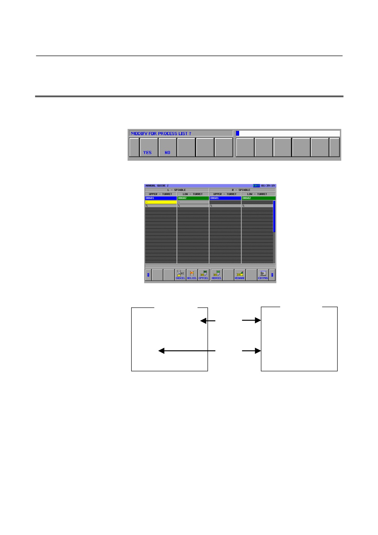
1. Press [DEL /].
SPINDLE 1
SPINDLE 2
TURRET 1
TURRET 2
TURRET 1
TURRET 2
N10 ROUGH
N10 DRILL
N20 TRANS
N20 TRANS
N30 FINE
N30 TAP
%
%
%
%
Deleting of optional block skip
SPINDLE 1
SPINDLE 2
TURRET 1
TURRET 2
TURRET 1
TURRET 2
N10 ROUGH
N10 DRILL
N20 TRANS
N20 TRANS
N30 FINE
N30 TAP
%
%
%
%
z Others
• Deletion processing is not done for the block which has G1992
and G1993.
G1992 S1;
G1992 S1;
/7 T0101;
T0101;
/7 G00 X0. Z0.;
G00 X0. Z0.;
/7 M01;
M01;
G1993;
G1993;
- 628 -
B-63874EN/04
MULTI-PATH LATHE FUNCTIONS 3.PROCESS LIST EDITING FUNCTION
3.6
DEALING OF THE PART PROGRAM WITH UNFITTED TO
PROCESS LIST FORM
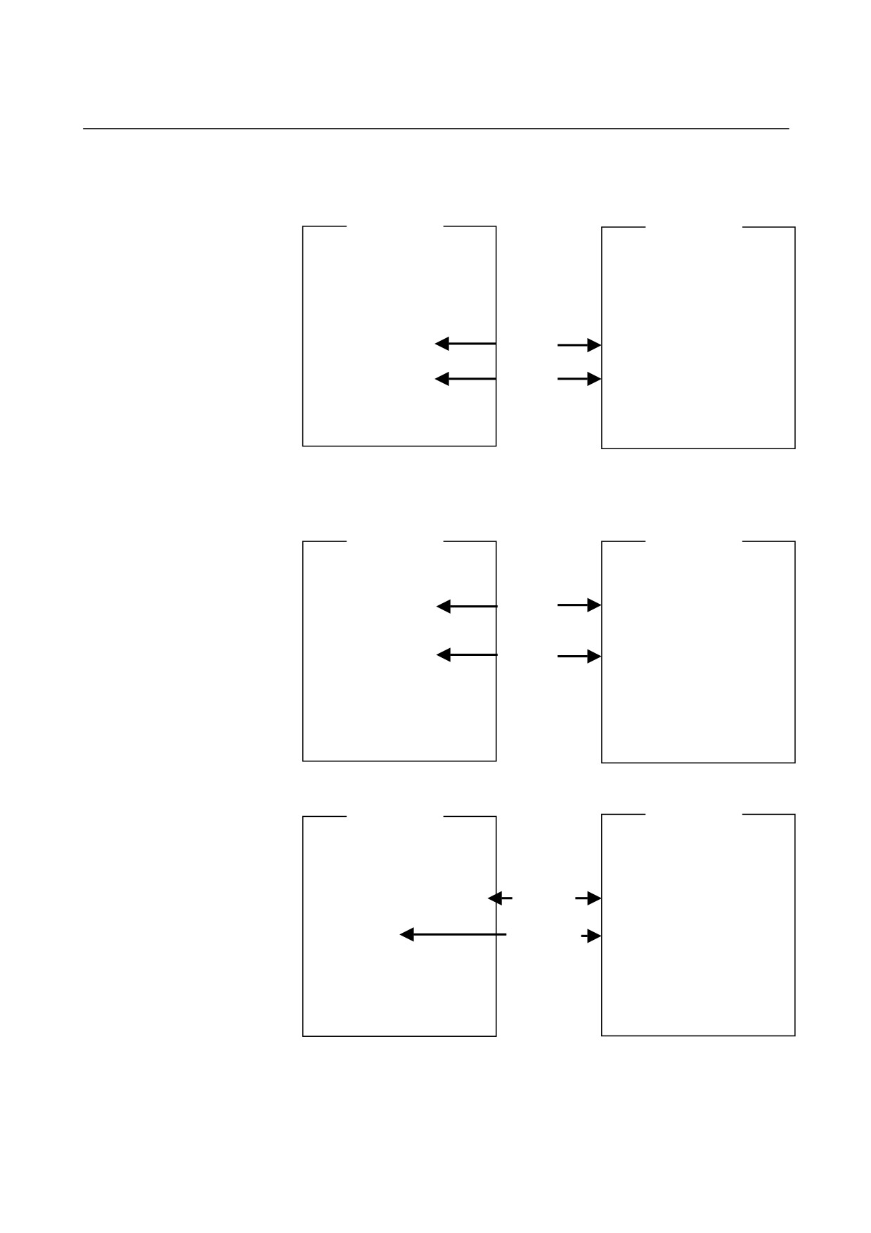
1.
The following screen will appear when NC program that is not
fitted to process list edit function is opened.
Press [YES], and process list edit function screen will appear.
NC program will be modified as follows.
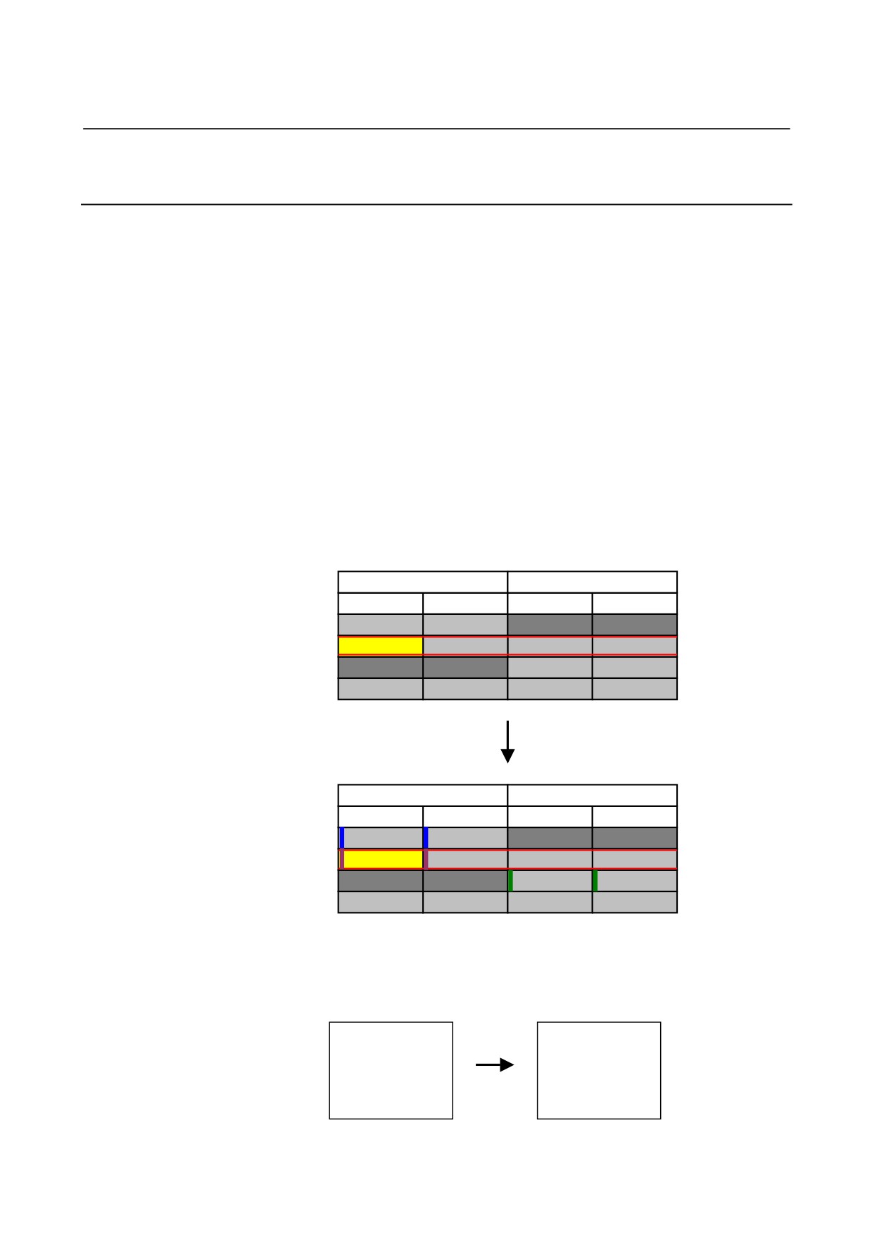
TURRET 1
TURRET 2
O0200
O0200
G1992 S1 (NONECELL);
G1992 S1 (NONECELL);
Add
(PROC01 : SP-1)
(PROC01 : SP-1)
(PROC02 : TRANS)
(PROC02 : TRANS)
(PROC03 : SP-2)
(PROC03 : SP-2)
G1993;
G1993;
Add
%
%
- 629 -
3.PROCESS LIST EDITING FUNCTION MULTI-PATH LATHE FUNCTIONS
B-63874EN/04
2.
And then, add (sum of all process - 1) piece cell by inserting cell
operation.
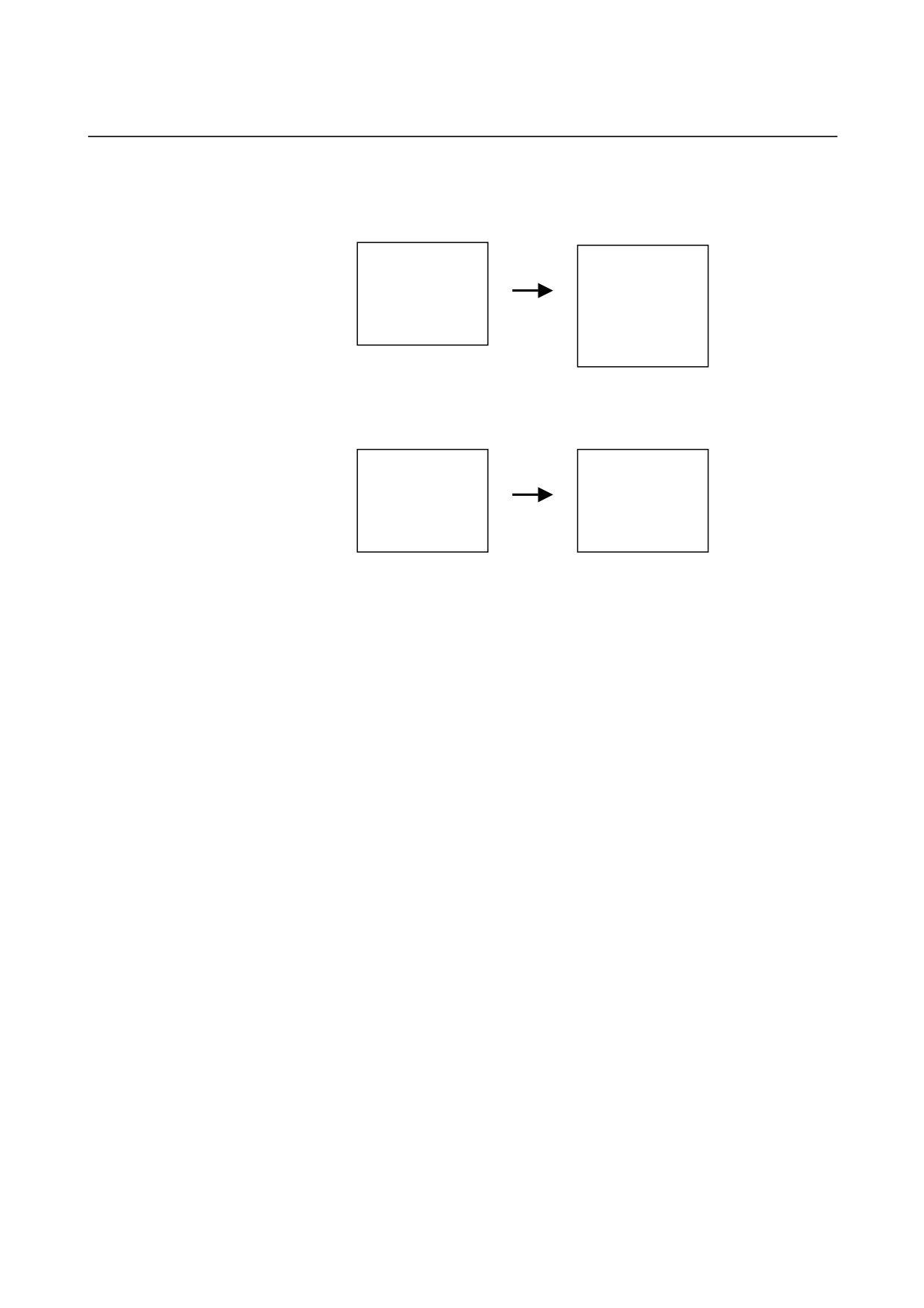
TURRET 1
TURRET 2
O0200
O0200
G1992 S1 (PROC1);
G1992 S1 (PROC1);
(PROC01 : SP-1)
(PROC01 : SP-1)
(PROC02 : TRANS)
(PROC02 : TRANS)
(PROC03 : SP-2)
(PROC03 : SP-2)
G1993;
G1993;
G1992 S1 (PROC2);
Add
G1992 S1 (PROC2);
G1993;
G1993;
G1992 S2 (PROC3);
Add
G1992 S2 (PROC3);
G1993;
G1993;
%
%
3.
Moreover press [EDTPRG], move the G1993 and G1992 blocks
between of processes using cut and paste in the normal edit
screen.
TURRET 1
TURRET 2
O0200
O0200
G1992 S1 (PROC1);
G1992 S1 (PROC1);
(PROC01 : SP-1)
(PROC01 : SP-1)
G1993;
Move
G1993;
G1992 S1 (PROC2);
G1992 S1 (PROC2);
(PROC02 : TRANS)
(PROC02 : TRANS)
G1993;
Move
G1993;
G1992 S2 (PROC3);
G1992 S2 (PROC3);
(PROC03 : SP-2)
(PROC03 : SP-2)
G1993;
G1993;
%
%
4.
Press [EDWORK] again, and set transfer.
TURRET 1
TURRET 2
O0200
O0200
G1992 S1 (PROC1);
G1992 S1 (PROC1);
(PROC01 : SP-1)
(PROC01 : SP-1)
G1993;
G1993;
G1992 S1 Q0 M200 (PROC2);
Change
G1992 S1 Q0 M200 (PROC2);
(PROC02 : TRANS)
(PROC02 : TRANS)
G1993 M201;
G1993 M201;
Change
G1992 S2 (PROC3);
G1992 S2 (PROC3);
(PROC03 : SP-2)
(PROC03 : SP-2)
G1993;
G1993;
%
%
5.
Finish transition work.
- 630 -
B-63874EN/04
MULTI-PATH LATHE FUNCTIONS 3.PROCESS LIST EDITING FUNCTION
3.7
FORMAT
Start Process : G1992
Sx : Select spindle
S1 : Spindle-1, S2 : Spindle-2
Qx : Attribute
Q0 : Transfer
Mx : Waiting M code
NC parameter from 8110 to 8111
Px : Waiting partner
Combination of existing path number
Finish process : G1993
Mx : waiting M code
NC parameter from 8110 to 8111
Px : waiting partner
Combination of existing path number
3.8
OTHERS
•
Waiting M code is recognized just in the same block for the
process beginning word and the process end word.
•
This function is not supported in the background mode.
(This is because a program to edit must be separately selected for
each path.)
•
As to moving cell and copying cell, the cell content is operated
as it is.
•
“/7”,
“/8”, and “/9” in the combination of “/” and figure for
optional block skip are reserved for “add /” function and “DEL /”
function. Therefore those word should not be used in the user
program freely.
•
A 1-path lathe does not support the "set waiting", "cancel
waiting", "set transfer", "cancel transfer", "add/", and "DEL/"
functions.
•
A 1-path lathe does not display the path name.
•
A 1-path and 1-spindle lathe does not display the spindle name.
- 631 -
V. TOOL MANAGEMENT FUNCTION
(FOR Series 16i/18i/21i ONLY)

B-63874EN/05
TOOL MANAGEMENT 1.ASSOCIATING TOOL NUMBERS WITH OFFSET NUMBERS
1
ASSOCIATING TOOL NUMBERS WITH
OFFSET NUMBERS
NOTE
1 To use tool management functions with MANUAL
GUIDE i, you require tool management function
options.
For details, refer to the manual issued by the
machine tool builder.
2 The tool management function of MANUAL GUIDE
i is not supported for the Series 30 i.
3 This function cannot be used with the MANUAL
GUIDE i simulator for the personal computer.
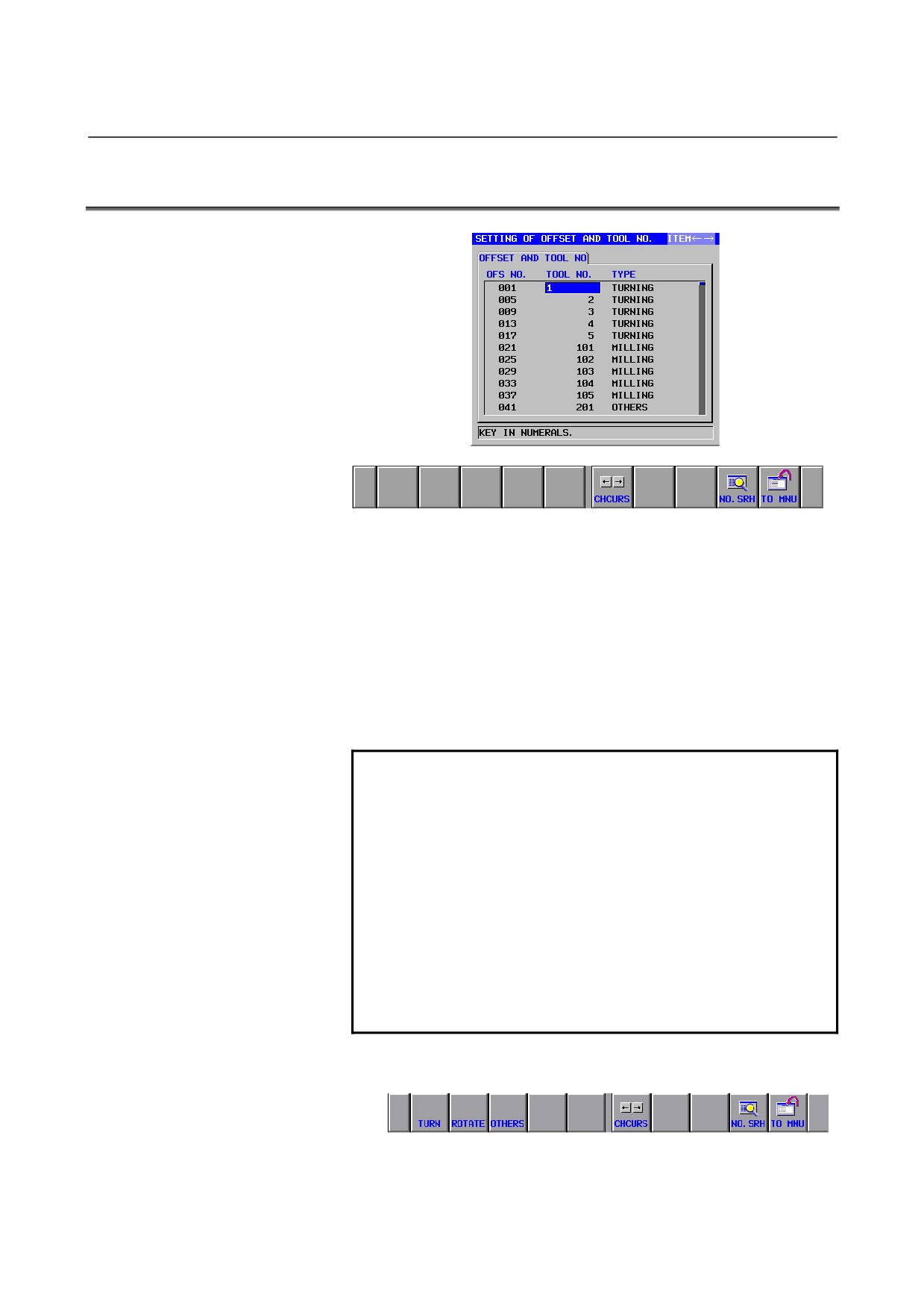
On the screen for associating a tool number with a offset number, set
the number of the tool that will use a offset number. When registered
on this screen, the tool number is registered in the tool management
data table, together with the offset number and the tool type.
This screen is effective only if bit 0 (ORT) of parameter No. 14823 is
1.
- 635 -
1.ASSOCIATING TOOL NUMBERS WITH OFFSET NUMBERS TOOL MANAGEMENT
B-63874EN/05
1.1
SELECTING THE SCREEN FOR ASSOCIATING A TOOL
NUMBER WITH A OFFSET NUMBER
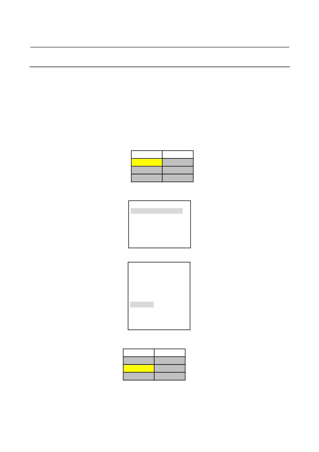
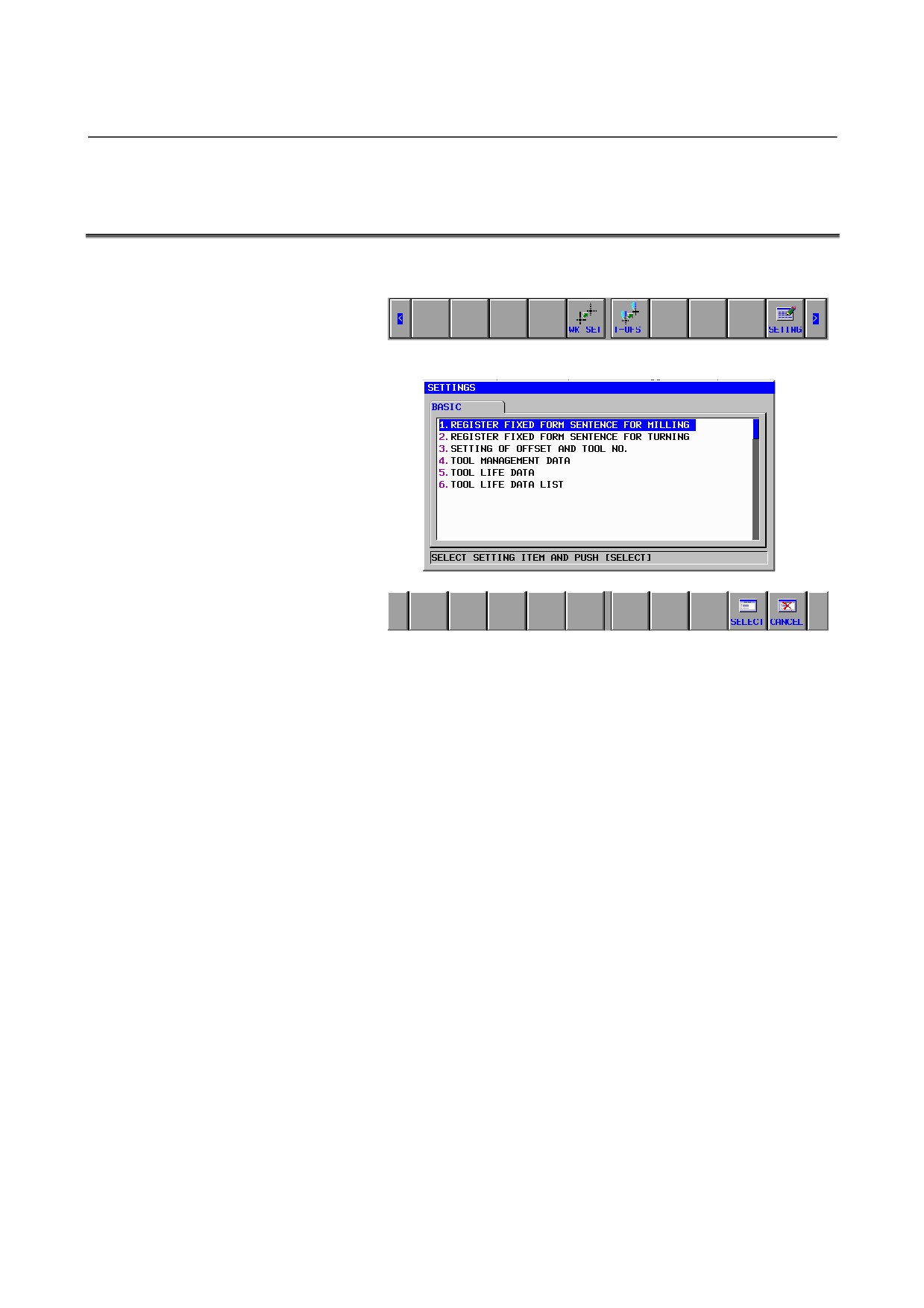
<1> Press [>] on the initial screen of each mode to display the soft
keys shown below, then press [SETING]:
<2> The following screen appears.
<3> From this screen, select “SETTING OF OFFSET NO. AND
TOOL NO.”, and the screen for associating a tool number with a
tool offset number appears.
- 636 -
B-63874EN/05
TOOL MANAGEMENT 1.ASSOCIATING TOOL NUMBERS WITH OFFSET NUMBERS
1.2
SCREEN DISPLAY ITEMS
Display items
OFS NO.:
You can only view offset numbers, and cannot set new ones.
The range of available offset numbers depends on the setting of
parameter No. 14824.
TOOL NO:
To register a new tool number in an empty tool number field,
enter a new number and press the INPUT key.
To invalidate an existing tool number, enter 0.
NOTE
When a tool number is entered, the associated
offset number is set in the “offset number” item of
the data having that tool number in the tool
management data table.
If the tool management data table does not contain
data having that tool number, the system searches
for tool management data having no tool number,
and the offset number associated with the entered
tool number is set in that tool management data.
If a tool number is deleted (0 is entered), all of the
tool management data having that tool number is
deleted.
TYPE:
To select the desired one, press the corresponding soft key.
- 637 -
1.ASSOCIATING TOOL NUMBERS WITH OFFSET NUMBERS TOOL MANAGEMENT
B-63874EN/05
Soft keys
[TO MNU]:
Return to the menu screen.
[CHCURS]:
Switches the system between cursor modes.
1.3
DISABLE WARNING MESSAGE
WRONG VALUE OF PARAMETER NO. 14824 :
Displayed if the value of parameter No. l4824 is outside the
range of 1 to 999 and “SETTING OF OFFSET NO. AND TOOL
NO.” is selected from the [SETING] menu.
INVALID INPUT :
Displayed if a tool number outside the valid range is entered.
TOOL NUMBER ALREADY EXISTS :
Displayed if the same tool number as that entered has already
been set.
TOOL MANAGEMENT DATA ACCESS ERROR :
Displayed if the system fails to read or write tool and offset
numbers.
- 638 -
B-63874EN/05
TOOL MANAGEMENT
2.VIEWING AND SETTING TOOL OFFSET VALUES
2
VIEWING AND SETTING TOOL OFFSET
VALUES
In addition to the conventional tool offset setting screen, a screen is
available which allows you to view and set tool offset values using
tool numbers and offset types.
This screen is effective only if bit 1 (TOD) of parameter No. 14823 is
1.
- 639 -
2.VIEWING AND SETTING TOOL OFFSET VALUES TOOL MANAGEMENT
B-63874EN/05
2.1
SELECTING THE TOOL NUMBER-BY-TOOL NUMBER
TOOL OFFSET SETTING SCREEN
<1> Press [>] on the initial screen of each mode to display the soft
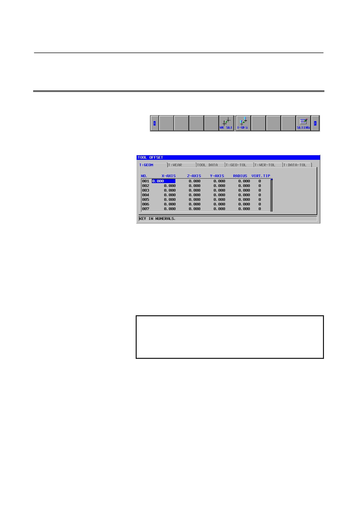
keys shown below:
<2> From this screen, press [T-OFS], and the tool offset setting
screen appears.
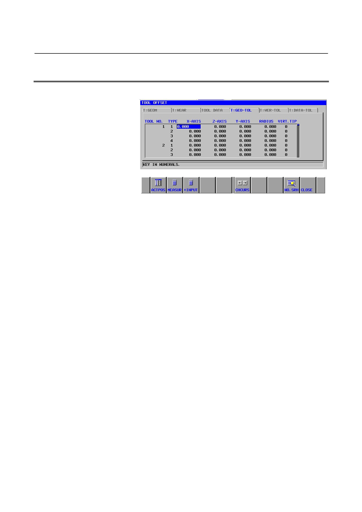
<3> Moving the cursor to the “T:GEO-TOL” tab causes the “Turning
geometric offset screen
(on a tool number by tool number
basis)” to appear.
<4> Moving the cursor to the
“T:WER-TOL” tab causes the
“Turning wear offset screen (on a tool number by tool number
basis)” to appear.
<5> Moving the cursor to “M:OFS-TOL” tab causes the “Milling
offset screen (on a tool number by tool number basis)” to appear.
NOTE
If the “T:GEOM”, “T:WEAR”, and “M:OFFSET” tabs
are selected, their respective conventional “T:Tool
geometric offset”, “T:Tool wear offset”, and “M tool
wear offset” screens appear.
- 640 -
B-63874EN/05
TOOL MANAGEMENT
2.VIEWING AND SETTING TOOL OFFSET VALUES
2.2
SCREEN DISPLAY ITEMS
(1) Turning geometric offset screen (on a tool number by tool number basis)
- Display items
TOOL NO.:
The tool numbers in the tool management data table are
displayed.
You cannot set new ones from this screen.
TYPE:
Offset types are displayed.
Values ranging from 1 to the “number of offset types” set in
parameter No. 14825 are displayed sequentially.
If the setting of parameter No. 14825 is 0, nothing is displayed in
the offset type column.
X-AXIS, Z-AXIS, Y-AXIS, RADIUS, VIRT. TIP:
The offset number corresponding to each combination of tool
number and offset type is determined, and the offset values of the
offset number are displayed.
The settings are made in the data for the offset number
determined with the combination of tool number and offset type.
Valid data range:
Depends on the setting of the tool offset (described later).
Data to be referenced:
Tool offset data
- Soft keys
[TO MNU]:
Return to the menu screen.
[CHCURS]:
Switches the system between cursor modes.
- 641 -