FANUC MANUAL GUIDE i. OPERATOR’S MANUAL - page 21
1.MULTI-PATH LATHE APPLICATION MULTI-PATH LATHE FUNCTIONS
B-63874EN/04
1.1
PREPARATION
The following preparation is needed in order to use this multi-path
lathe application.
NOTE
When using the path selection soft key of Manual
Guide i, make a setting so that the reset key on the
MDI panel is enabled for all paths (bit 0 of
parameter No. 8100 is 0).
(If the reset key is enabled on a path-by-path basis,
(bit 0 of parameter No. 8100 is 1), the path
selected in the NC is reset regardless of which path
is selected in Manual Guide i.)
1.1.1
Machine Configuration Setting
These parameters are set according to the machine configuration.
14702#1
0 : No sub-spindle is provided.
1 : A sub-spindle is provided.
14701#1
0 : Tool post 1 cannot be used with spindle 2.
1 : Tool post 1 can be used with spindle 2.
14701#2
0 : Tool post 1 is placed above spindle 1.
1 : Tool post 1 is placed under spindle 1.
14701#3
0 : Tool post 1 is placed above spindle 2.
1 : Tool post 1 is placed under spindle 2.
27401#0
0 : Tool post 2 cannot be used with spindle 1.
1 : Tool post 2 can be used with spindle 1.
27401#1
0 : Tool post 2 cannot be used with spindle 2.
1 : Tool post 2 can be used with spindle 2.
27401#2
0 : Tool post 2 is placed above spindle 1.
1 : Tool post 2 is placed under spindle 1.
27401#3
0 : Tool post 2 is placed above spindle 2.
1 : Tool post 2 is placed under spindle 2.
27402#0
0 : Tool post 3 cannot be used with spindle 1.
1 : Tool post 3 can be used with spindle 1.
27402#1
0 : Tool post 3 cannot be used with spindle 2.
1 : Tool post 3 can be used with spindle 2.
27402#2
0 : Tool post 3 is placed above spindle 1.
1 : Tool post 3 is placed under spindle 1.
27402#3
0 : Tool post 3 is placed above spindle 2.
1 : Tool post 3 is placed under spindle 2.
14706
: Directions of the three basic axes of spindle 1
14706
: Directions of the three basic axes of spindle 2
16 : Right-handed coordinate system, right = +Z, up = +X
17 : Right-handed coordinate system, right = -Z, up = +X
18 : Right-handed coordinate system, right = -Z, up = -X
19 : Right-handed coordinate system, right = +Z, up = -X
27400#0
0 : Tool post is selection by the software key.
1: Tool post is selection by the PMC signal.
- 582 -
B-63874EN/04
MULTI-PATH LATHE FUNCTIONS
1.MULTI-PATH LATHE APPLICATION
1.1.2
Set Icon for Selected Turret
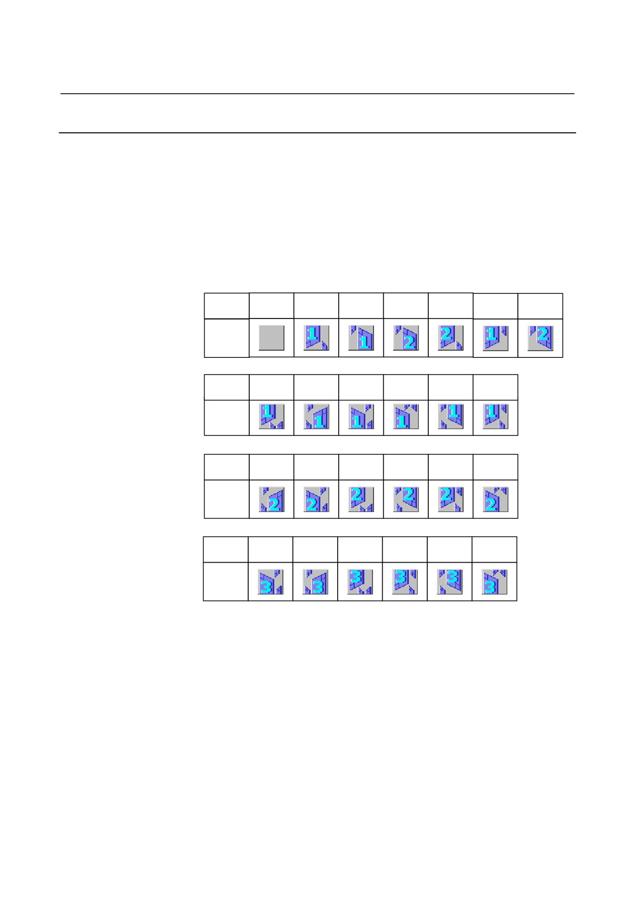
The icon displayed when tool path-1 or path-2 are selected is set by
the parameter.
27410 : icon number when path-1 is selected.
27411 : icon number when path-2 is selected.
27412 : icon number when path-3 is selected.
•
Icon number list
Icon
number
0
1
2
3
4
5
6
icon
Icon
number
10
11
12
13
14
15
icon
Icon
number
20
21
22
23
24
25
icon
Icon
number
30
31
32
33
34
35
icon
- 583 -
1.MULTI-PATH LATHE APPLICATION MULTI-PATH LATHE FUNCTIONS
B-63874EN/04
1.2
OPERATIONS OF MULTI-PATH LATHE
1.2.1
Changing Screens for Each Path
On the MANUAL GUIDE i for multi-path lathe, screens and
operations are done on each path respectively.
On its screen, the icon for selected path will be displayed at the upper
right part.
1.2.1.1 Changing by a soft-key
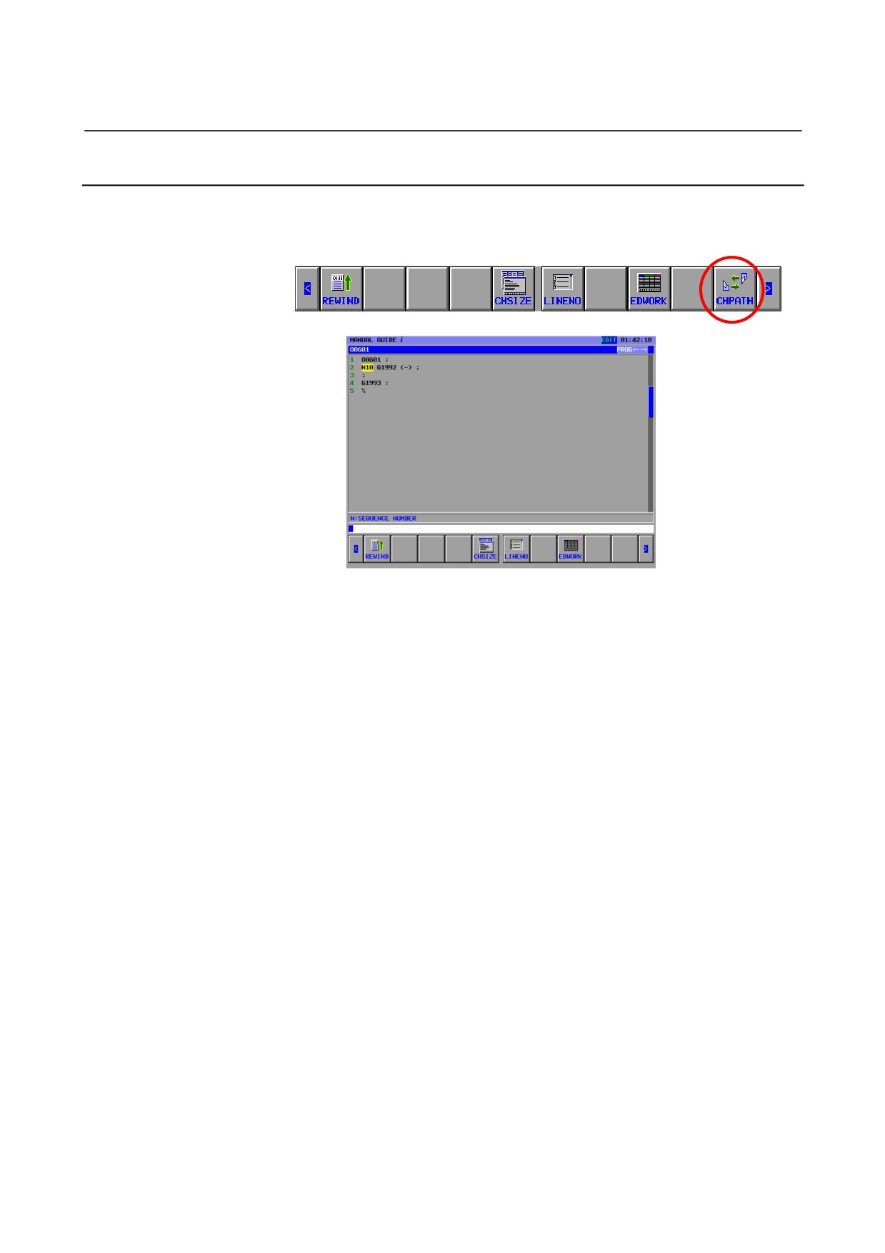
On the each screen, CHPATH soft-key will be displayed.
Press [CHPATH], the displayed turret will be changed.
In case of 2-path system : turret-1 > turret-2 > turret-1 > …
In case of 3-path system : turret-1 > turret-2 > turret-3 > turret-1 > …
1.2.1.2 Changing by a switch on a machine operator’s panel
Connected with the path selection signal
(HEAD<G063#0>,
HEAD2<G062#7>), change the display of MANUAL GUIDE i.
HEAD
HEAD2
Displayed
(G63.0)
(G62.7)
Path number
0
0
1
1
0
2
0
1
3
NOTE
Select turret, display returns to a basic screen of
each mode when the system is changed
occasionally.
- 584 -
B-63874EN/04
MULTI-PATH LATHE FUNCTIONS
1.MULTI-PATH LATHE APPLICATION
1.3
ANIMATION FOR MULTI-PATH LATHE
The tool path and animation for multi-path lathe are available.
NOTE
1 When machining simulation is started, it is
necessary to set MEM mode for all path.
2 Displaying is not done for the combination where
the parameter is set to the combination of the main
axis and the cutlery stand as invalidity.
1.3.1
Tool Path Drawing During Machining and Tool Path
Machining Simulation
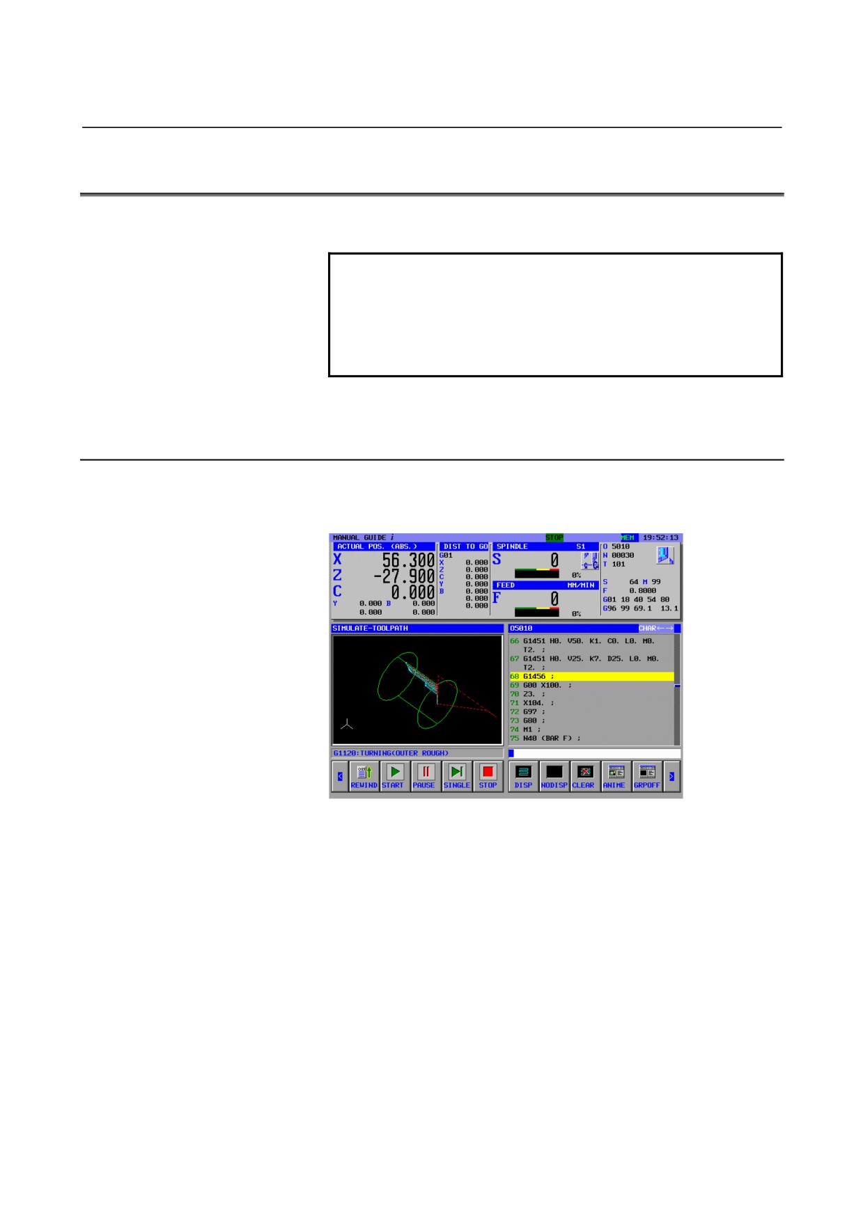
In the tool path drawing during machining (tool path), machining
simulation (tool path), the turret selected now is drawn.
When the path (turret) is changed during drawing, the drawing starts
from halfway status.
When the mode of changed path (turret) is other of MEM mode, the
drawing will stop.
- 585 -
1.MULTI-PATH LATHE APPLICATION MULTI-PATH LATHE FUNCTIONS
B-63874EN/04
1.3.2
Machining Simulation (Animation)
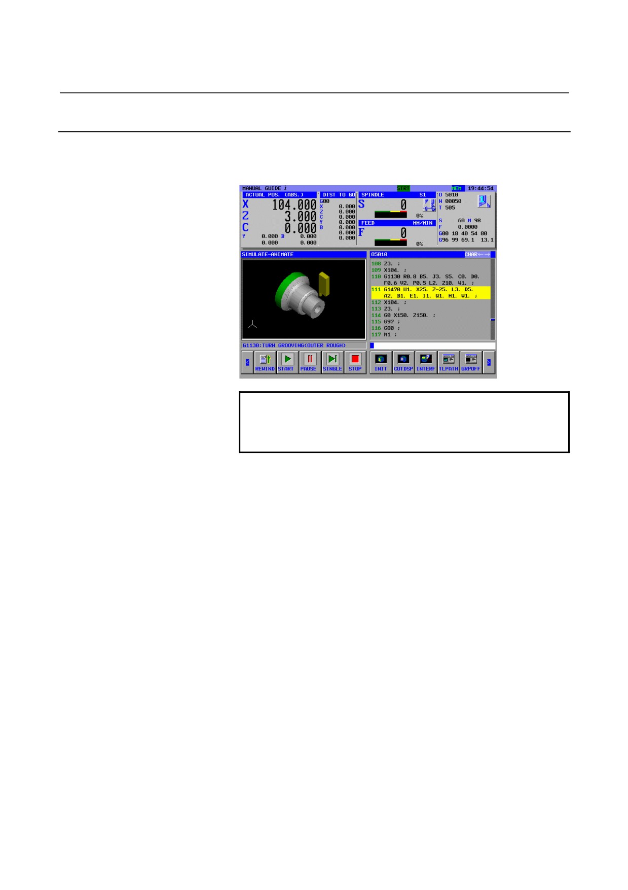
In the machining simulation (animated), the Drawing for each turret is
executed simultaneously, regardless of selected turret.
NOTE
Only animation for the spindle selected latest
between both turrets is displayed. (The animation
for the other spindle is not displayed.)
- 586 -
B-63874EN/04
MULTI-PATH LATHE FUNCTIONS
1.MULTI-PATH LATHE APPLICATION
1.4
MACHINING SIMULATION FOR EACH PATH
In the multi-path system of MANUAL GUIDE i, the machining
simulation is performed only at the selected path by the R signal.
In the multi-path system of MANUAL GUIDE i, the machining
simulation is performed only at the selected path by a R signal that is
set at the parameter No.27309 (The first figure is “bit” and the other
figure is the R signal number.).
For example, with 2 paths system
- At Path 1, the parameter No.27309=1001
- At Path 2, the parameter No.27309=2001
Then,
- At Path 1, if R100.1 is 1
- At Path 2, if R200.1 is 1
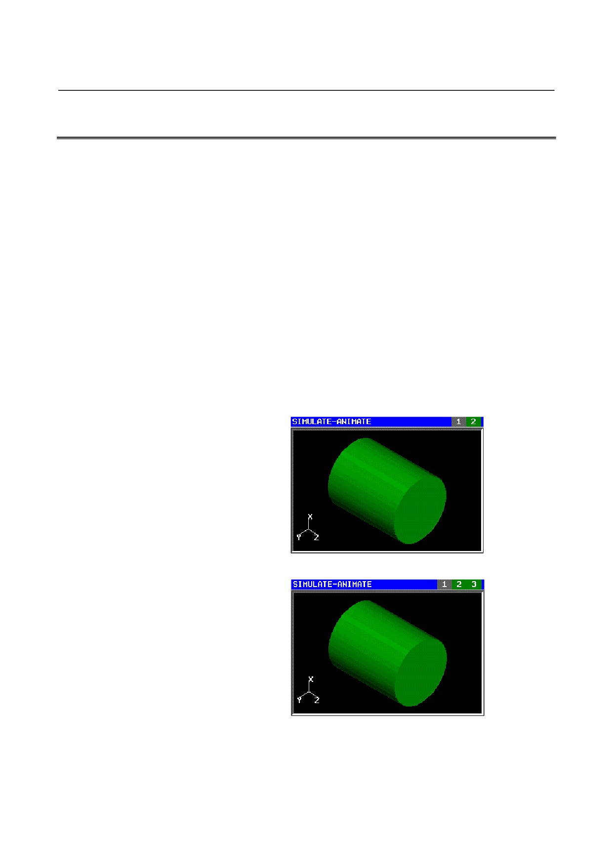
machining simulation is performed at each path. The status of the
signal of each path is displayed at a title bar of simulation window.
Green is the status for enable the simulation to be performed. Gray is
the status for disable.
Ex.1 With 2 paths system, the signal of Path 1 is 0 and the one of
Path 2 is 1.
Ex.2 With 3 paths system, the signal of Path 1 is 0 and the ones of
Path 2/3 are 1.
- 587 -
1.MULTI-PATH LATHE APPLICATION MULTI-PATH LATHE FUNCTIONS
B-63874EN/04
NOTE
1
If M code for waiting other paths is commanded,
the machining simulation is in pausing for
performing of the same M code at other paths. So,
if this function is made available in use of M code
for waiting, it must be made disabled by the
management such as the M code is disabled by
using a signal of PMC for ignoring it.
2
This function needs the optional function MANUAL
GUIDE i Animated Drawing.
3
In drawing during machining, R signal that is set at
the parameter No. 27309 is disabled.
4
If the parameter No.27309 is not set at any paths,
this function is disabled.
5
R signal, which is set at the parameter No. 27309,
is available in converting into NC formatted
program, too. The NC statement converting
function is available only at the path in displaying.
So, when the R signal at the path, which is the
object for NC statement converting, is off, the
warning message “TURN THIS PATH'S
SIMULATE-SWITCH ON” is displayed.
6
In the NC statement converting function, the status
of the R signal is not displayed.
7
Even if the R signal of a path is turned from “ON“ to
“OFF” in the machining simulation, the machining
simulation is not pausing but is performed at the
path.
8
Even if the R signal of a path is turned from “ON“ to
“OFF” in the machining simulation, [SINGLE] and
[PAUSE] are not available at the path. In short,
these soft keys are available at the path when the
R signal is on.
9
If [STOP] or the RESET is pressed in the
machining simulation, it stops at all paths for all
status of the R signal.
10 If any paths are in machining, the machining
simulation can not be performed.
11 To perform the machining simulation, the mode
must be MEM at the selected path for displaying. If
it is turned to another path in the other mode than
MEM in the machining simulation, the machining
simulation is stopped and the animation window
turns off.
- 588 -

B-63874EN/04
MULTI-PATH LATHE FUNCTIONS
1.MULTI-PATH LATHE APPLICATION
1.5
OTHERS
NOTE
1 Guidance window for machining cycle data
entering screen are displayed following the specific
coordinate system (upper direction X+: right
direction Z+: parameter 14706=16).
2 The material is common with path-1 and path-2.
The registration of the material is possible from
path-1 and path-2. (When registered from both
path, the only latest is effective.)
- 589 -
2.SIMULTANEOUS ALL PATH DISPLAY / EDITING FUNCTION MULTI-PATH LATHE FUNCTIONS B-63874EN/04
2
SIMULTANEOUS ALL PATH DISPLAY /
EDITING FUNCTION
- 590 -
B-63874EN/04 MULTI-PATH LATHE FUNCTIONS
2.SIMULTANEOUS ALL PATH DISPLAY / EDITING FUNCTION
2.1
OUTLINE
In the multi-path lathe, simultaneous all path display and edit function.
Became available.
Supported machine construction is as follows.
•
2-path 2-spindle
•
3-path 2-spindle
In order to use this feature, the following option is necessary.
•
Multi-path lathe function for MANUAL GUIDE i
- 591 -
2.SIMULTANEOUS ALL PATH DISPLAY / EDITING FUNCTION MULTI-PATH LATHE FUNCTIONS B-63874EN/04
2.2
DETAILS
2.2.1
How to Start
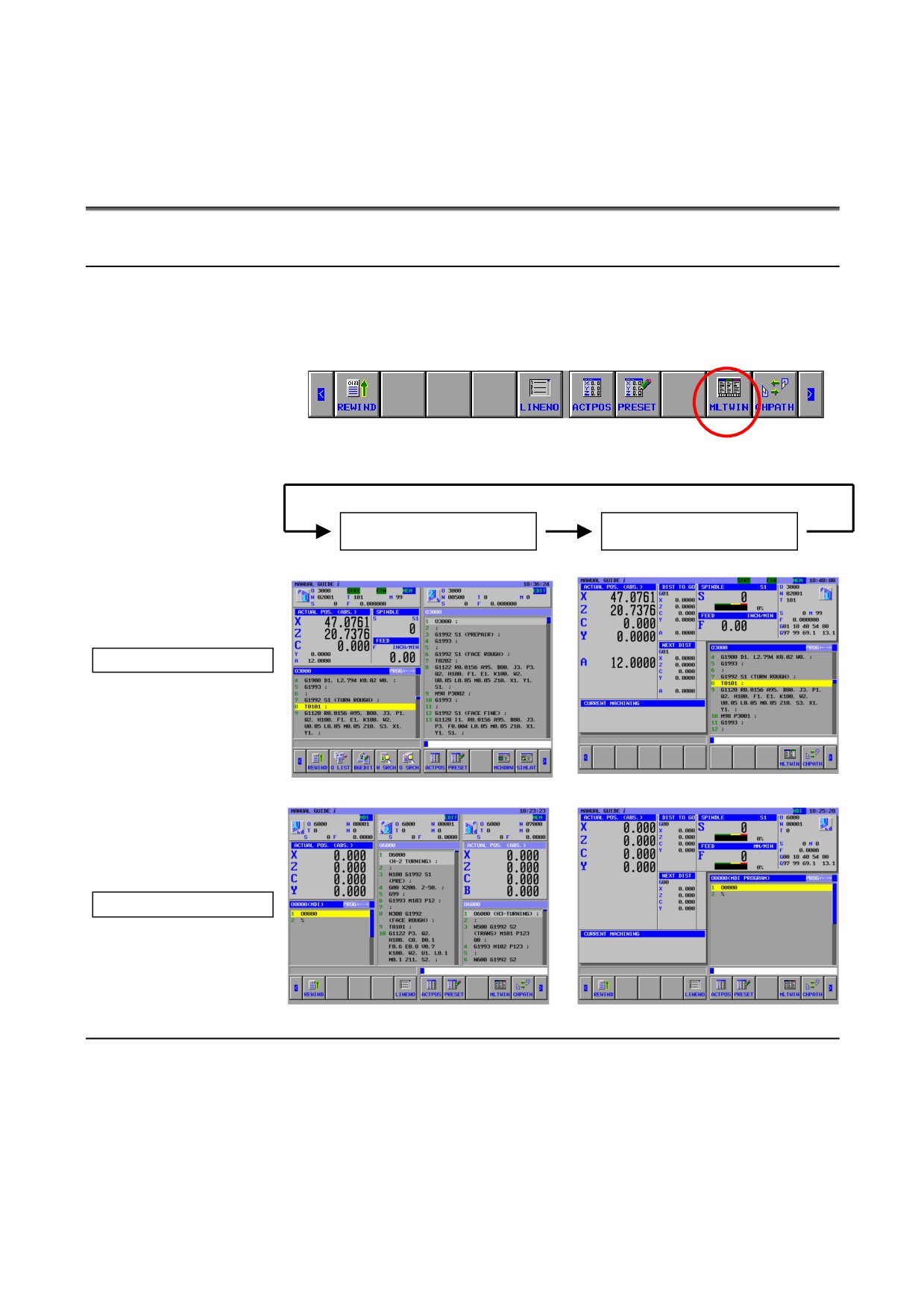
[MLTWIN] is displayed next to [CHPATH] in each basic mode.
(If the setting that [CHPATH] is not used is specified, the softkey is
arranged to the same position.)
When [MLTWIN] is pressed, the display mode is changed as follows.
All path display
Single path display
In the case of 2-path
In the case of 3-path
2.2.2
How to Finish
Press [MLTWIN] again, and the display mode will be changed to
single display mode.
- 592 -
B-63874EN/04 MULTI-PATH LATHE FUNCTIONS
2.SIMULTANEOUS ALL PATH DISPLAY / EDITING FUNCTION
2.3
SCREEN CONFIGURATION
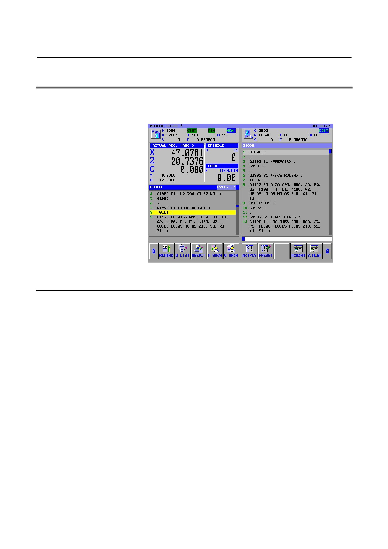
The screen composition of simultaneously for all path display and edit
function is explained.
2.3.1
Display Position of Each Path
•
2-path
First path : left side
Second path : right side
•
3-path
The display position of each path will be decided automatically
according to following parameter.
14701#1 : head 1 cannot be used in spindle 2 or can
(0/1)
27401#0 : head 2 cannot be used in spindle 1 or not
(0/1)
27401#1 : head 2 cannot be used in spindle 2 or can
(0/1)
27402#0 : head 3 cannot be used in spindle 1 or not
(0/1)
27402#1 : head 3 cannot be used in spindle 2 or can
(0/1)
- 593 -

2.SIMULTANEOUS ALL PATH DISPLAY / EDITING FUNCTION MULTI-PATH LATHE FUNCTIONS B-63874EN/04
2.3.2
Status Display Part
The status display part display the status of each path.
This part is displayed in all operation mode.
Icon of displayed path.
Operation mode
MDI, MEM, RMT, EDIT, HND, JOG, TJOG, THND, INC, REF
Alarm status
ALM
Emergency stop status
EMG
Reset status
-RESET-
Automatic operation status
STOP, HOLT, STRT
Axis motion and dwelling status
MTN, DWL
Executing auxiliary functions
FIN
O : Program number (O number)
N : Sequence number (N number)
T : Modal T code commanded data
M : Modal M code commanded data
S : Modal S code commanded data
F : Modal F code commanded data
- 594 -
B-63874EN/04 MULTI-PATH LATHE FUNCTIONS
2.SIMULTANEOUS ALL PATH DISPLAY / EDITING FUNCTION
2.3.3
Current Position Display Part
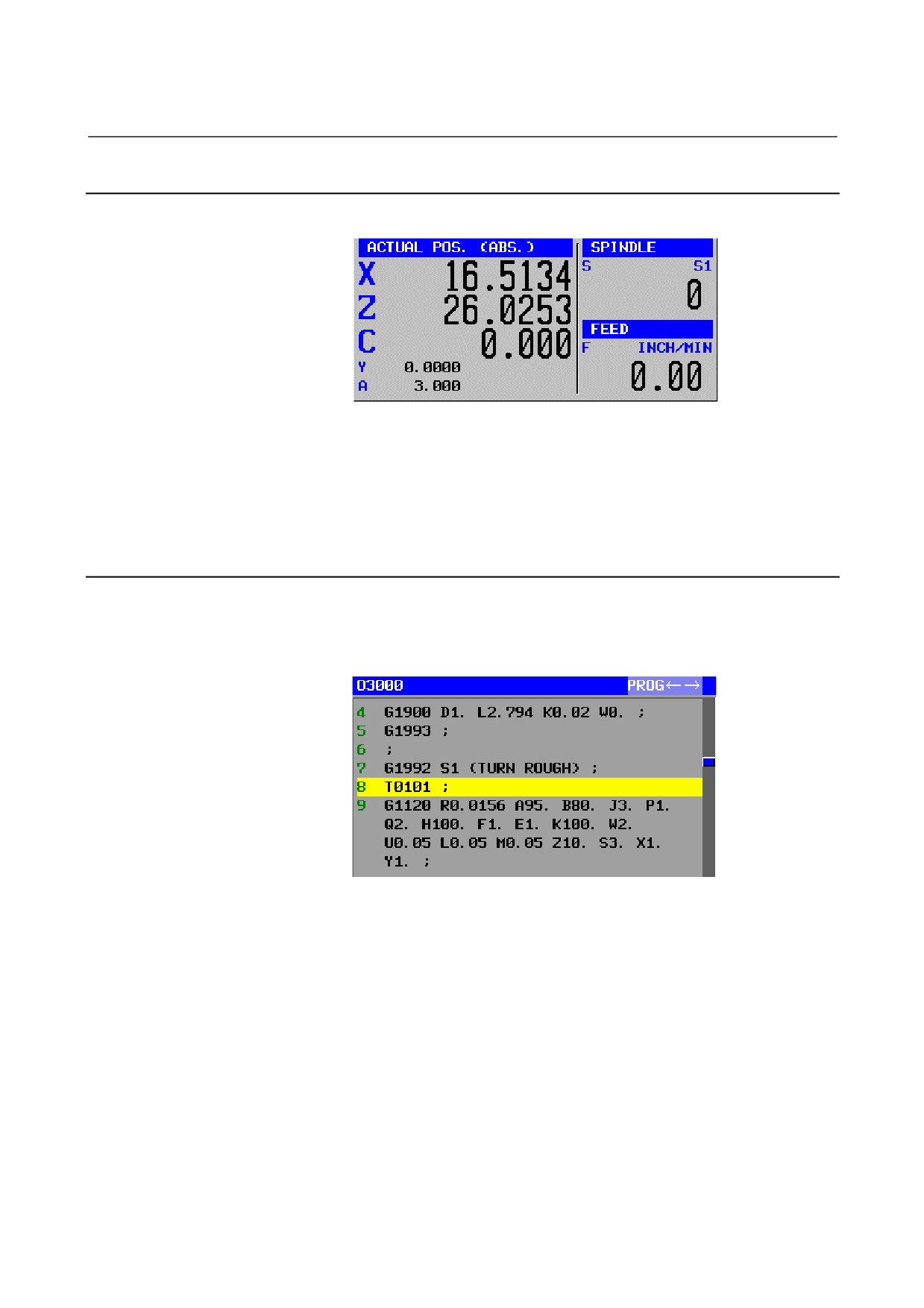
This screen is displayed out of EDIT mode.
Using
[ACTPOS], absolute position, relative position, machine
position, and distance to go in turn.
(In case of 2-path, actual spindle speed and actual feed rate are also
displayed.)
2.3.4
Program Display Part
This screen will be displayed in all operation mode.
(In case of EDIT mode, this part will be extended because current
position part is lost.)
- 595 -
2.SIMULTANEOUS ALL PATH DISPLAY / EDITING FUNCTION MULTI-PATH LATHE FUNCTIONS B-63874EN/04
2.4
HOW TO SELECT PATH
Select the target path using [CHPATH] or path selection signal. As for
the selected path, the title of position and program display part is
displayed in blue.
(As for the not selected path, the title will be
displayed in light blue.)
For the selected path, a similar operation system to the normal screen
is supported.
(In case of the screen which is not supported all path display mode,
the single path display mode will be selected automatically.)
2.5
OTHERS
•
The screen which need full size, like animation, convert to nc
program, process list edit, chsize, and so on, will change to full
screen display automatically.
•
It is impossible to operate for the not selected path.
•
In
3-path, actual spindle speed and actual feed rate is not
supported because the display area is too small.
- 596 -

B-63874EN/04
MULTI-PATH LATHE FUNCTIONS 3.PROCESS LIST EDITING FUNCTION
3
PROCESS LIST EDITING FUNCTION
Available CNC types..
•
2 CPU 2 path lathe CNC
Lathe with 2 turrets and 2 spindles, and each turret can perform to
both of spindle#1 and spindle#2 respectively.
•
2 CPU 3 path lathe CNC
Lathe with 3 turrets and 2 spindles, turret#1 can perform to both
of spindle#1 and spindle#2, turret#2 can perform to spinlde#2,
and turret#3 can perform to spindle#1.
•
1 CPU 1 path lathe CNC
Lathe with 2 spindles, 1 turret can perform to both of spindle#1
and spindle#2.
NOTE
1 Process list editing is available only at EDIT mode.
Under background editing mode, it is not available.
2 When you use a process list editing function, you
need a lathe machining cycle optional function.
Furthermore, if you use [Add /] and [Del /]
functions, you need an optional block skip function.
- 597 -
3.PROCESS LIST EDITING FUNCTION MULTI-PATH LATHE FUNCTIONS
B-63874EN/04
3.1
PREPARATION
3.1.1
Parameter
The following parameter is needed to be set.
•
14703#3 = 1 : Use the process list edit function
In case of using Add / function and Del / function,
•
14701#6 = 1: Use program check function for each spindle.
- 598 -
B-63874EN/04
MULTI-PATH LATHE FUNCTIONS 3.PROCESS LIST EDITING FUNCTION
3.2
START AND END OPERATIONS
3.2.1
Start
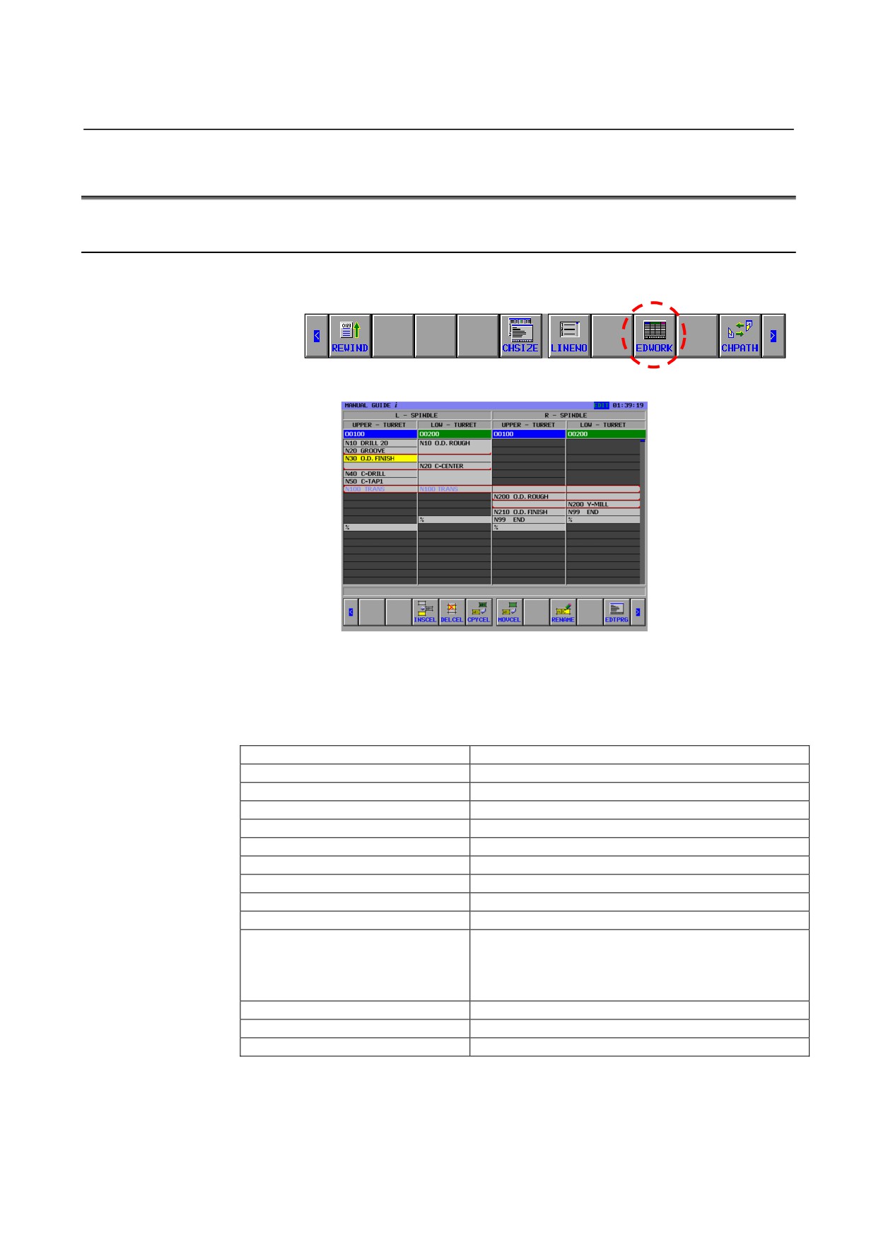
Set CNC to EDIT mode, and press [<] or [>], following soft-keys will
appear.
Press this [EDTCEL], process table edit screen will appear.
If the consistency of G1992 and G1993 is lacked when the process
table edit function start, the process table edit function will not appear,
and line number and message of the warning will be shown at the
lower left.
Warning Message
Description
Top G1992 is short
G1993 appears without G1992.
G1993 is duplicate.(P=x/L=xxxx)
G1993 is doubled because of no G1992 in the interval.
LAST G1993 is short.
Program ends without the last G1993
G1992 is duplicate. (P=x/L=xxxx)
G1992 is doubled because of no G1993 in the interval.
M CODE is duplicate. (P=x/L=xxxx)
The same waiting M code is used again.
Waiting target is short. (P=x/L=xxxx)
Waiting M code does not exist at waiting target with P.
Illegal waiting order.(P=x/L=xxxx)
The order waiting M code appears is not correct..
No program.
The program selected now does not exist.
No waiting M code. (P=x/L=xxxx)
Waiting M code is lost at transfer.
Illegal P command. (P=x/L=xxxx)
The value of P command is different even if the value
of waiting M code is the same.
Own path number is lost in the P command of waiting
M code.
Illegal S command. (P=x/L=xxxx)
Spindle number is not correct.
WAITING EXIST. (P=%d/L=%ld)
A waiting M code exists for a 1-path lathe.
TRANS. EXIST.(P=%d/L=%ld)
A Q command exists for a 1-path lathe.
- 599 -
3.PROCESS LIST EDITING FUNCTION MULTI-PATH LATHE FUNCTIONS
B-63874EN/04
3.2.2
End
Press [RETURN] soft-key, and the simultaneously for all path display
screen appears, which also appears when
[MLTWIN] soft-key is
pressed in the normal EDIT mode.
Changing CNC mode, the screen change for the other mode.
- 600 -
B-63874EN/04
MULTI-PATH LATHE FUNCTIONS 3.PROCESS LIST EDITING FUNCTION
3.3
DISPLAY CONTENTS
3.3.1
Cell
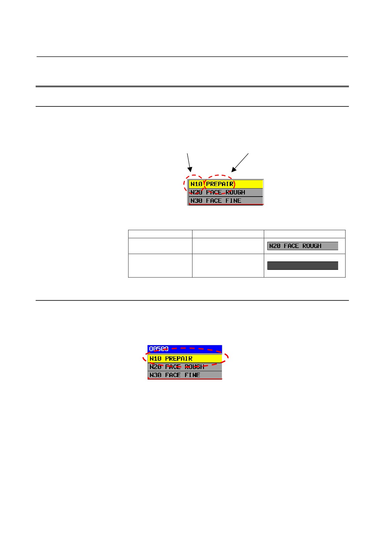
Each process is corresponded to the frame in the table which is called
a cell.
Only following information is displayed in this frame.
Sequence number
Comment
Moreover, there are following kinds of cells.
Kind
Description
Graphic
Cell where the process
Normal Cell
exists.
There is frame for
Input Impropriety Cell
display, but the process
does not exist for it.
3.3.2
Current Cell
The target cell for the operation is shown. It is possible to move with
the cursor key. As for the selected cell, the background color is
displayed in yellow.
- 601 -
3.PROCESS LIST EDITING FUNCTION MULTI-PATH LATHE FUNCTIONS
B-63874EN/04
3.3.3
Spindle
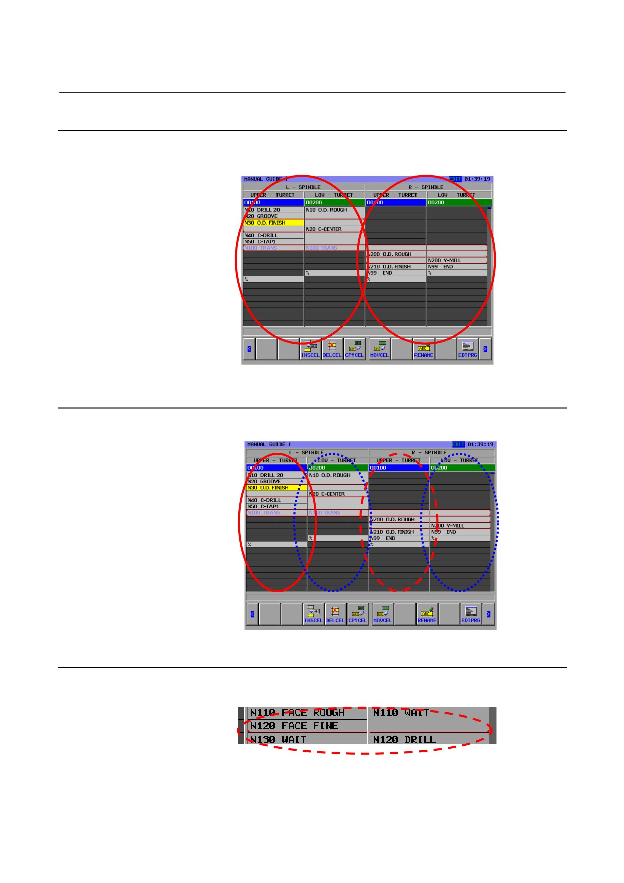
First of all, each process is arranged according to the spindle.
The operator can see the process belongs to which spindle at a glance.
3.3.4
Turret
Each process is arranged further in the spindle according to the turret.
3.3.5
Waiting Line
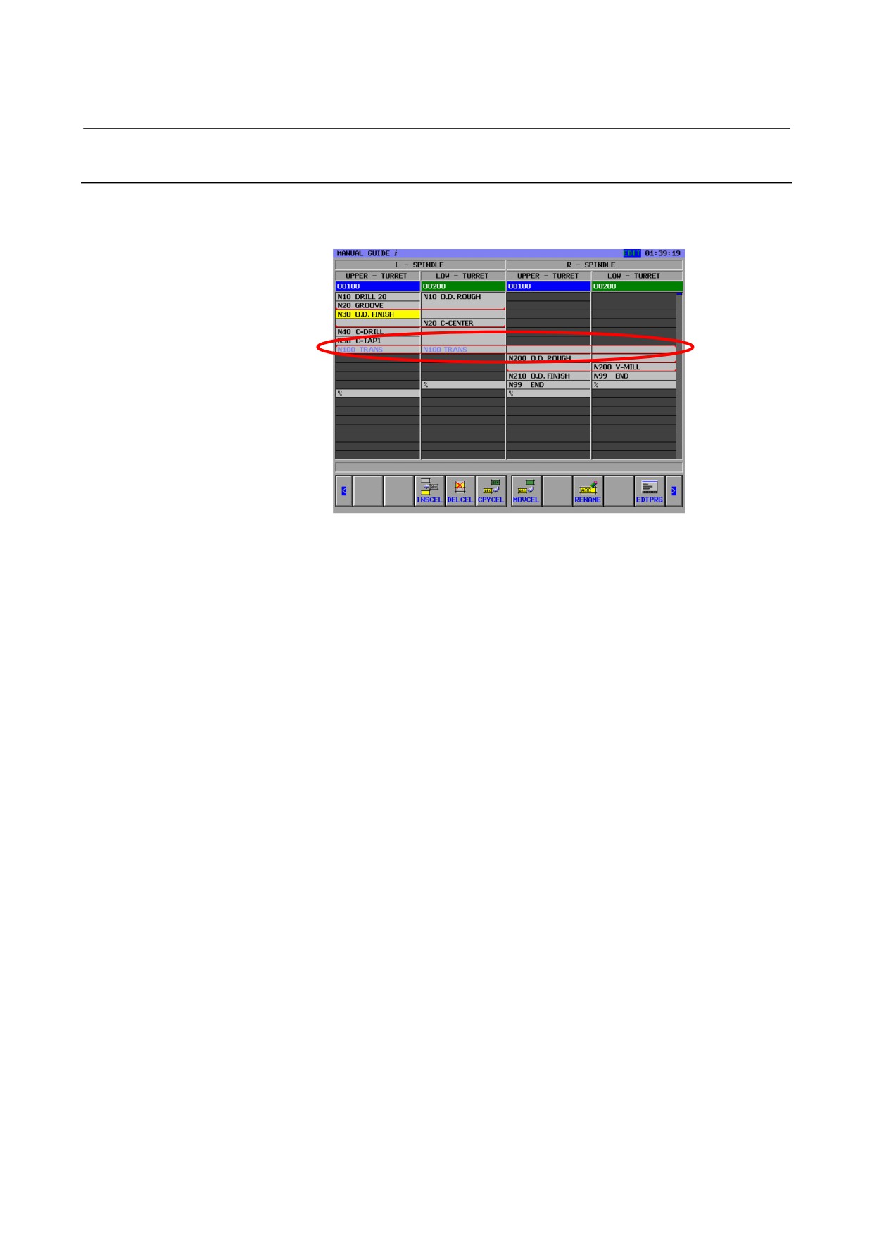
The line that shows waiting exists is displayed.
- 602 -
B-63874EN/04
MULTI-PATH LATHE FUNCTIONS 3.PROCESS LIST EDITING FUNCTION
3.3.6
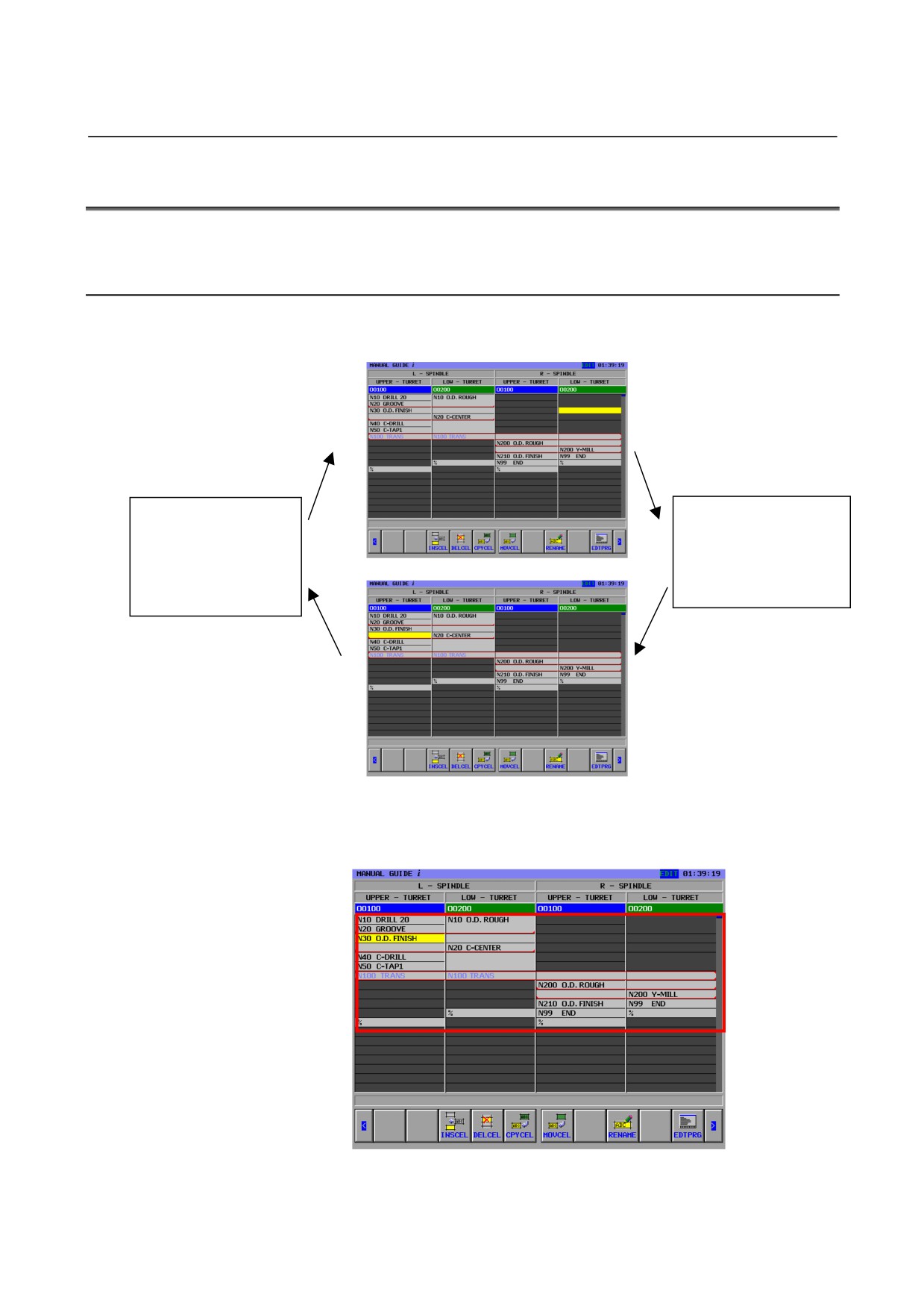
Transfer
When transfer exists, that is displayed by blue character.
Transfer is arranged at the top and bottom.
- 603 -
3.PROCESS LIST EDITING FUNCTION MULTI-PATH LATHE FUNCTIONS
B-63874EN/04
3.4
BASIC OPERATIONS
The following operations can be done in each cell.
3.4.1
Basic Operations
A current cell can be moved up, down, right, and left by operating the
cursor key.
Directing left at the
Directing right at the
leftmost cell, current
rightmost cell, current
cell moves on the
cell moves on the
rightmost cell upper by
leftmost cell lower by
one piece.
one piece.
Operating page key, it is possible to scroll entire table up and down by
one page.
The range of the movement of the cursor is from the head to % about
each row.
- 604 -

B-63874EN/04
MULTI-PATH LATHE FUNCTIONS 3.PROCESS LIST EDITING FUNCTION
3.5
EDITING OPEARTIONS
The following operations are available on each cell.
Operation
Description
INSCEL
Insert process to the upper part of the specified cell.
DELCEL
Delete the specified cell.
CPYCEL
Copy the specified cell to the specified position.
MOVCEL
Move the specified cell to the specified position.
RENAME
Modify the comment of the specified cell.
EDTPRG
Edit the program including the specified cell.
STWAIT *
Set the waiting to the specified cell.
CLWAIT *
Release the specified waiting.
STTRNS *
Set the transfer to the specified cell.
CLTRNS *
Release the specified transfer.
ADD / *
Add the optional block skip.
DEL / *
Delete the optional block skip.
NOTE
Operations marked with * cannot be used on
1-path lathe.
- 605 -
3.PROCESS LIST EDITING FUNCTION MULTI-PATH LATHE FUNCTIONS
B-63874EN/04
3.5.1
Insertion of a Cell
•
Function
• Add a process.
• Add the process to the upper side.
• In NC program,
Process start block : G1992 Sx (xxxx)
Process end block : G1993
These codes are inserted automatically.
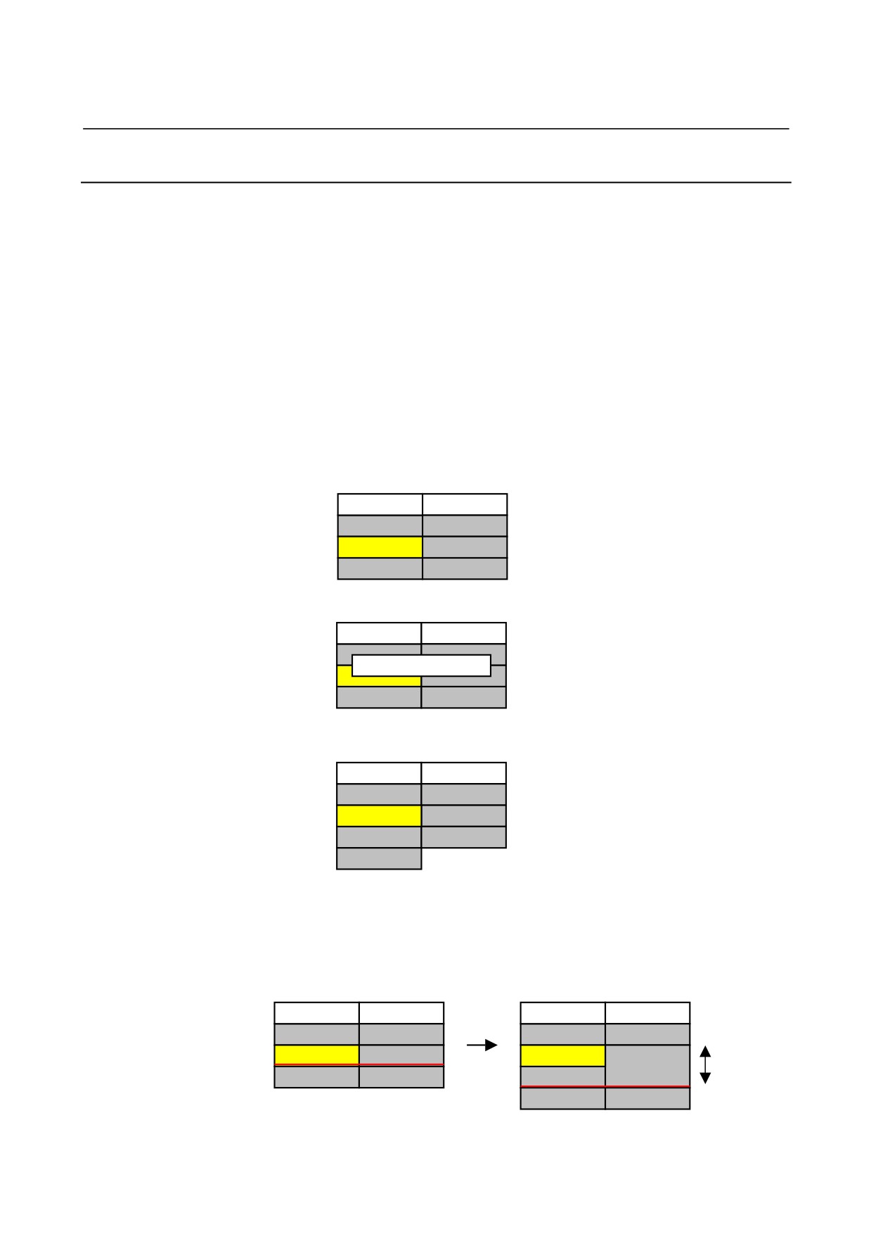
z Basic operation
1. Move cursor to the cell to be inserted.
TURRET 1
TURRET 2
N10 ROUGH
N10 DRILL
N20 FINE
N20 TAP
%
%
2. Press [INSCEL] soft-key.
TURRET 1
TURRET 2
N10 ROUGH
N10 DRILL
The dialog for the process name input
PROC NAME MIDDLE
N
is displayed.
Input MIDDLE as an example.
%
%
3. Press OK, and the process will be inserted.
TURRET 1
TURRET 2
N10 ROUGH
N10 DRILL
Cursor moves to the new cell.
MIDDLE
N20 TAP
N20 FINE
%
(When cancel is pressed, return to
%
previous state.)
z Others
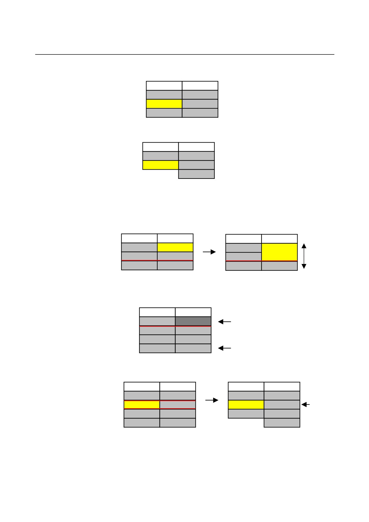
• In case of having waiting in the lower, for not breaking the
waiting line, modify the height of the cell of other row that
have the waiting to twice.
TURRET 1
TURRET 2
TURRET 1
TURRET 2
N10 ROUGH
N10 DRILL
N10 ROUGH
N10 DRILL
N20 FINE
N20 TAP
N20 TAP
Height of
Insert
cell
%
%
N20 FINE
becomes
%
%
twice.
- 606 -
B-63874EN/04
MULTI-PATH LATHE FUNCTIONS 3.PROCESS LIST EDITING FUNCTION
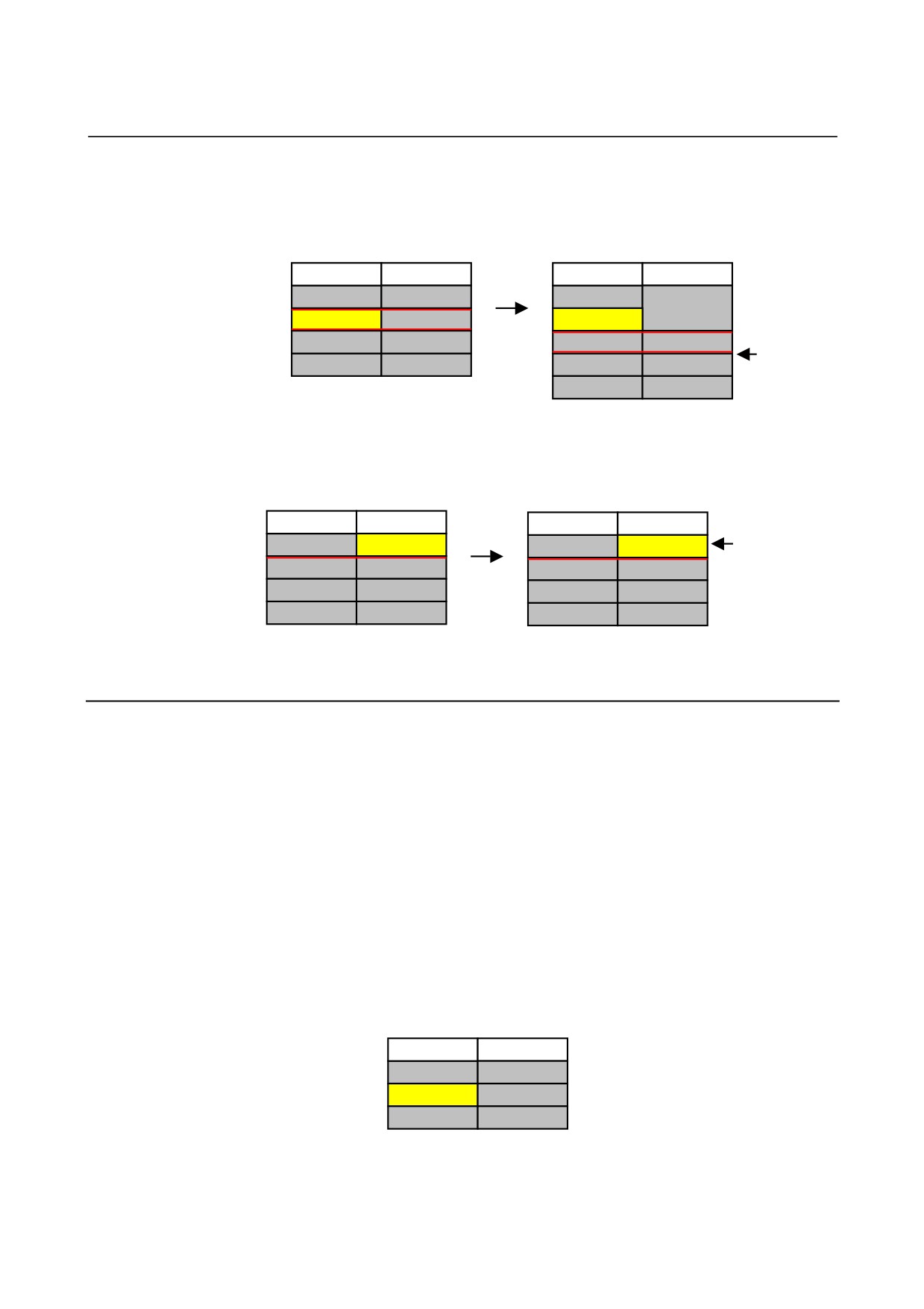
• If the new cell is inserted on the cell having the waiting, the
waiting do not move to the new cell. (Transfer is also similar.)
TURRET 1
TURRET 2
TURRET 1
TURRET 2
N10 ROUGH
N10 DRILL
N10 ROUGH
N10 DRILL
N20 TRANS
N20 TRANS
Leave
N30 FINE
N30 TAP
Insert
N20 TRANS
N20 TRANS
transfer
as it is.
%
%
N30 FINE
N30 TAP
%
%
• Even if current cell is input impropriety one, insertion of the
cell is possible. After insertion, the entire table is displayed
again, as the result, there are some case where overwriting is
executed.
TURRET 1
TURRET 2
TURRET 1
TURRET 2
As the
result,
N10 ROUGH
CAN’T
N10 ROUGH
overwrite on
N20 MIDDLE
N10 DRILL
N20 MIDDLE
N10 DRILL
the input
N30 FINE
N20 TAP
Insert
N30 FINE
N20 TAP
impropriety
%
%
%
%
cell.
3.5.2
Deletion of a Cell
z Function
• Delete the process at the current cursor.
• In NC program,
Process start block : G1992 Sx (xxxx)
(Normal block)
Process end block : G1993
These blocks are deleted automatically.
z Basic operation
1. Move cursor to the cell to be deleted.
TURRET 1
TURRET 2
N10 ROUGH
N10 DRILL
N20 FINE
N20 TAP
%
%
- 607 -
3.PROCESS LIST EDITING FUNCTION MULTI-PATH LATHE FUNCTIONS
B-63874EN/04
2. Press [DELCEL] soft-key.
TURRET 1
TURRET 2
“ARE YOU SURE YOU WANT TO
N10 ROUGH
N10 DRILL
DELETE IT ?” is displayed in the
N20 FINE
N20 TAP
message display part.
Press [YES] or [NO].
%
%
3. Press [YES], and the process will be deleted.
TURRET 1
TURRET 2
N10 ROUGH
N10 DRILL
The cursor position is left as it is.
%
N20 TAP
(In case of “NO”, returns to former
%
state.)
z Others
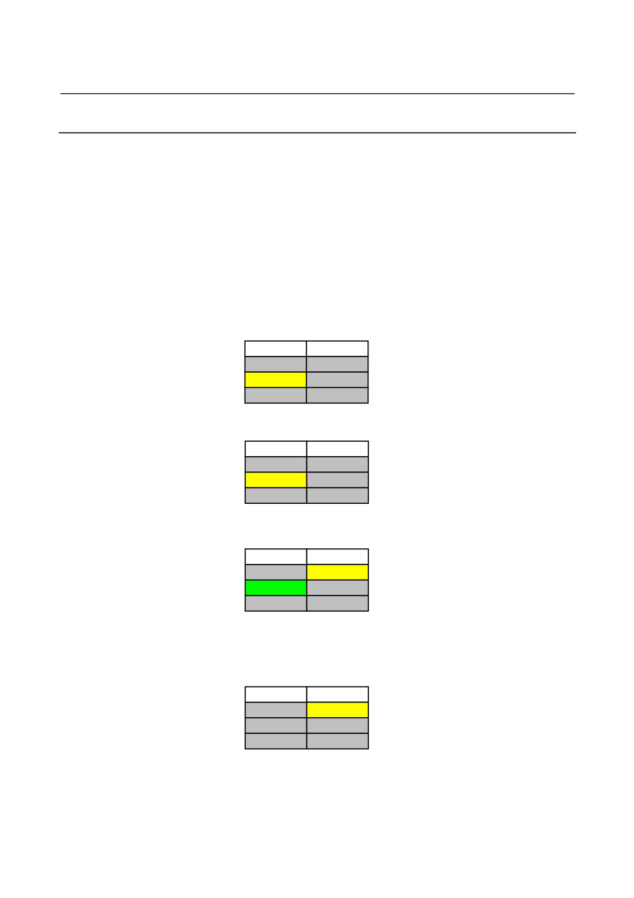
• In case of having waiting in the lower line, for not breaking the
waiting line by adjusting after deletion, modify the height of
the cell that have the waiting to twice.
TURRET 1
TURRET 2
TURRET 1
TURRET 2
N10 ROUGH
N10 DRILL
N10 ROUGH
N20 TAP
Height
of cell
N20 FINE
N20 TAP
N20 FINE
Delete
becomes
%
%
%
%
twice.
• There is the cell that cannot be deleted.
TURRET 1
TURRET 2
N10 ROUGH
Input impropriety cell
N20 MIDDLE
N10 DRILL
N30 FINE
N20 TAP
%
%
% cell
• When the cell that have waiting, the waiting is released.
(Transfer as well)
TURRET 1
TURRET 2
TURRET 1
TURRET 2
N10 ROUGH
N10 DRILL
N10 ROUGH
N10 DRILL
Release the
N20 TRANS
N20 TRANS
N30 FINE
N20 TRANS
partner of
Delete
N30 FINE
N30 TAP
%
N30 TAP
transfer,
too.
%
%
%
(When one of the waiting member among the 3-path is deleted,
the rest waiting will not be released.)
- 608 -
B-63874EN/04
MULTI-PATH LATHE FUNCTIONS 3.PROCESS LIST EDITING FUNCTION
3.5.3
Copying of a Cell
z Function
• Copy the process
• In NC program,
Start process block : G1992 Sx (xxxx)
End process block : G1993
The blocks between above two blocks and comment in the
G1992 block arc copied automatically.
z Basic Operation
1. Move the cursor to the source cell.
TURRET 1
TURRET 2
N10 ROUGH
N10 DRILL
N20 FINE
N20 TAP
%
%
2. Press [CPYCEL] soft-key.
TURRET 1
TURRET 2
N10 ROUGH
N10 DRILL
*N20 FINE
N20 TAP
Add “*” to the top of the source cell.
%
%
3. Move cursor to the destination cell.
TURRET 1
TURRET 2
N10 ROUGH
N10 DRILL
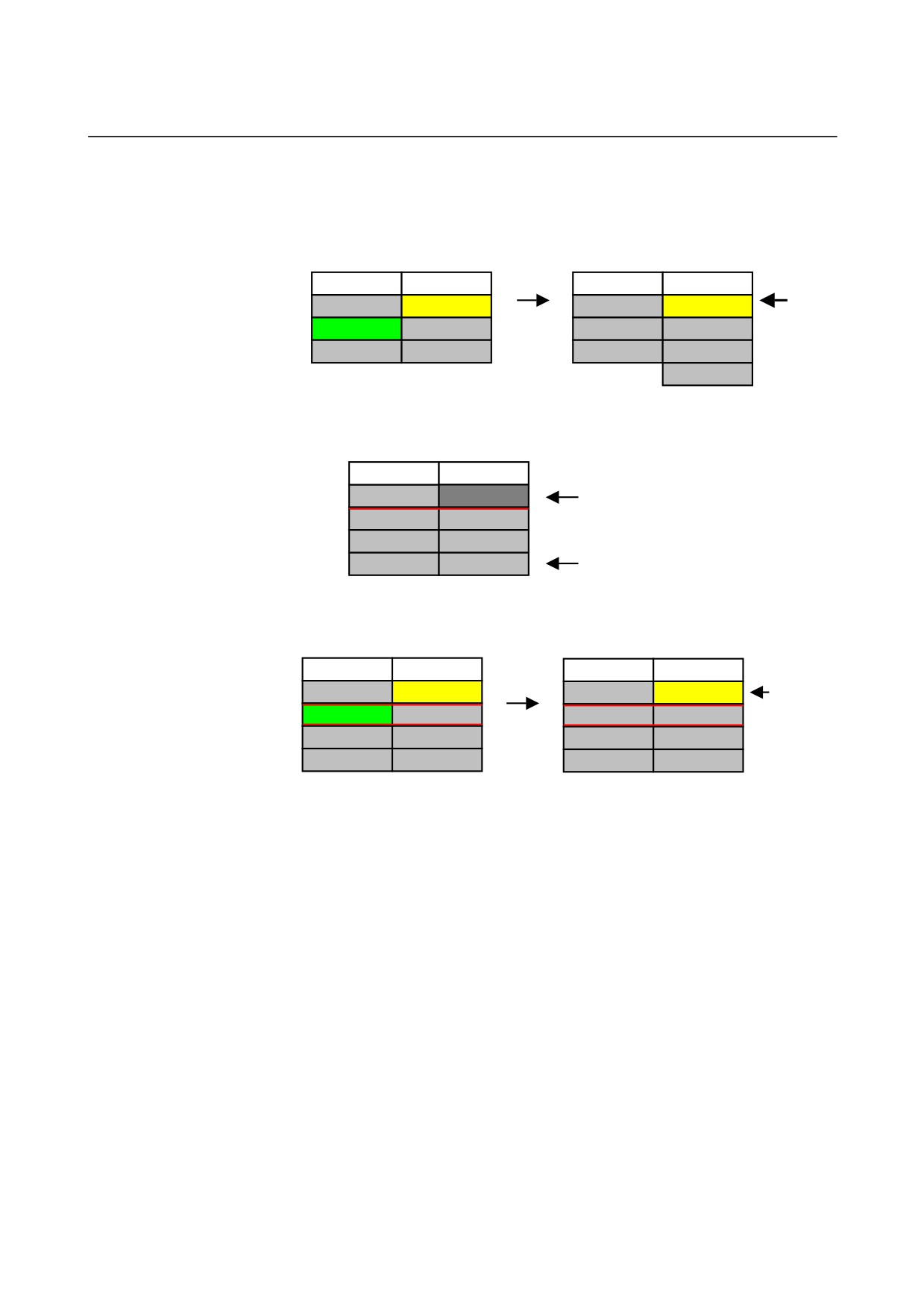
Moreover background color of the source
cell become green.
*N20 FINE
N20 TAP
%
%
Press [CPYCEL] or [CANCEL].
4. Press [CELCPY], overwrite copy will be done if destination
process is vacant.
TURRET 1
TURRET 2
N10 ROUGH
N10 FINE
(When cancel is pressed, return to
N20 FINE
N20 TAP
previous state.)
%
%
- 609 -
3.PROCESS LIST EDITING FUNCTION MULTI-PATH LATHE FUNCTIONS
B-63874EN/04
z Others
• When the destination process is not vacant, it is possible to
select overwrite, insert, and cancel.
TURRET 1
TURRET 2
TURRET 1
TURRET 2
Insert
N10 ROUGH
N10 DRILL
N10 ROUGH
FINE
&
*N20 FINE
N20 TAP
Select
N20 FINE
N10 DRILL
copy
%
%
Insert
%
N20 TAP
%
• There is the cell that cannot be specified as source and
destination.
TURRET 1
TURRET 2
N10 ROUGH
Input impropriety cell
N20 MIDDLE
N10 DRILL
N30 FINE
N20 TAP
%
%
% cell
• The waiting and transfer will not be copied.
TURRET 1
TURRET 2
TURRET 1
TURRET 2
N10 ROUGH
N10 DRILL
N10 ROUGH
N20 TRANS
Transfer
will not
*N20 TRANS
N20 TRANS
N20 TRANS
N20 TRANS
be copied.
N30 FINE
N30 TAP
Copy
N30 FINE
N30 TAP
%
%
%
%
- 610 -
B-63874EN/04
MULTI-PATH LATHE FUNCTIONS 3.PROCESS LIST EDITING FUNCTION
3.5.4
Moving of a Cell
z Function
• Move the process (The source cell is removed.)
• In NC program,
Start process block : G1992 Sx (xxxx)
End process block : G1993
The blocks between above two blocks and comment in the
G1992 block are moved automatically.
z Basic Operation
1. Move the cursor to the source cell.
TURRET 1
TURRET 2
N10 ROUGH
N10 DRILL
N20 FINE
N20 TAP
%
%
2. Press [CPYCEL].
TURRET 1
TURRET 2
N10 ROUGH
N10 DRILL
*N20 FINE
N20 TAP
Add “*” to the top of the source cell.
%
%
3. Move cursor to the destination cell.
TURRET 1
TURRET 2
N10 ROUGH
N10 DRILL
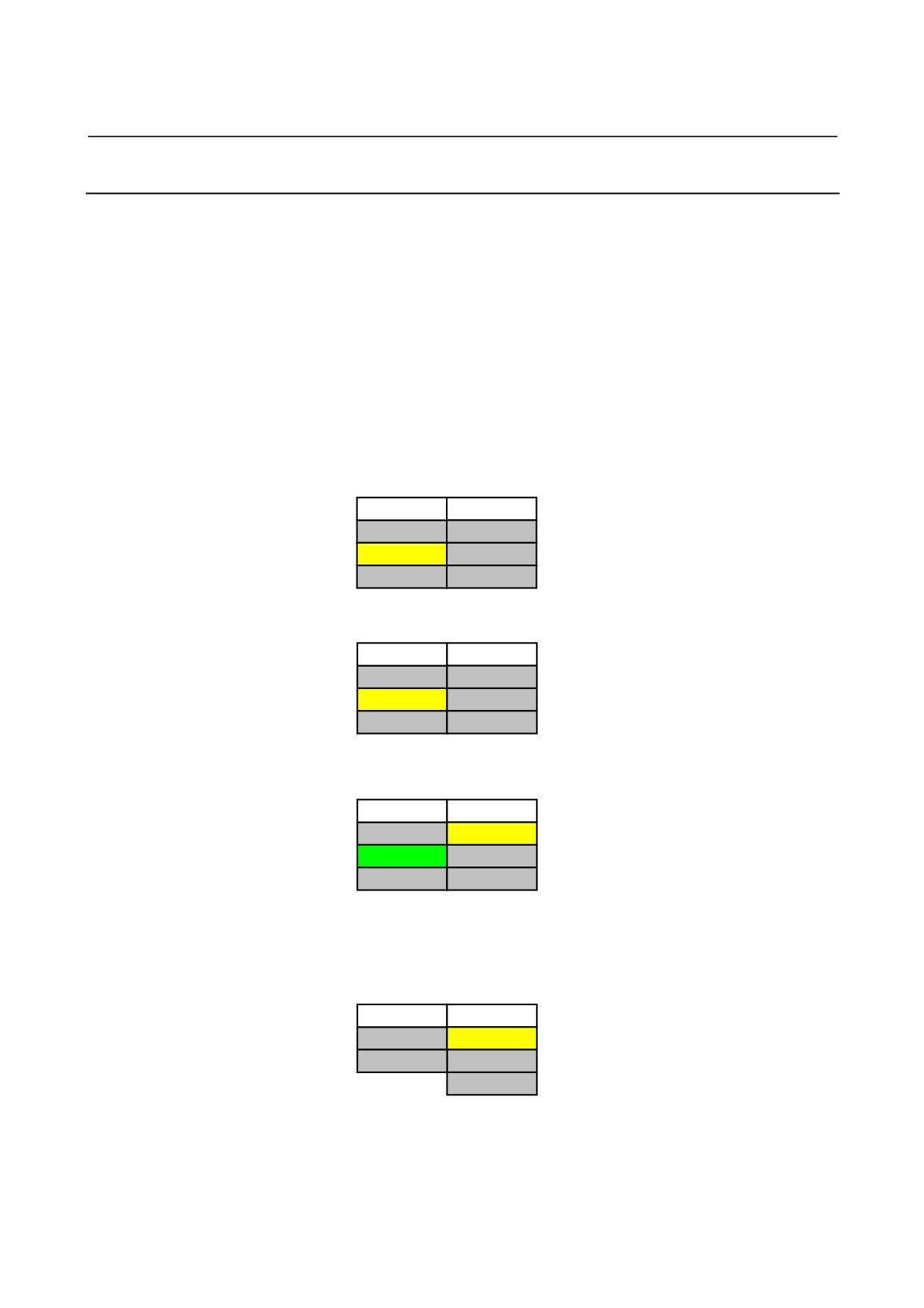
Moreover background color of
the
source cell become green.
*N20 FINE
N20 TAP
%
%
Press [CPYCEL] or [CANCEL].
4. Press [CELMOV], overwrite move will be done if destination
process is vacant.
TURRET 1
TURRET 2
N10 ROUGH
N10 FINE
%
N20 TAP
(When cancel is pressed, return to
previous state.)
%
- 611 -