FANUC MANUAL GUIDE i. OPERATOR’S MANUAL - page 20
2.TURNING
CYCLE MACHINING TYPES
B-63874EN/05
CORNER INFO
Data item
Meaning
I
CORNER TYPE-3
For corner (3)
[NOTHIN]
: Specifies neither chamfering nor
corner rounding (initial value).
[CHAMFR] : Specifies chamfering.
[ARC]
: Specifies corner rounding.
J
CORNER SIZE
Chamfer amount or corner radius (radius value,
positive value)
Remark) This data item is indicated only when
[CHAMFR] or [ARC] is selected for
CORNER TYPE-3.
Q
CORNER TYPE-4
For corner (4)
[NOTHIN]
: Specifies neither chamfering nor
corner rounding (initial value).
[CHAMFR] : Specifies chamfering.
[ARC]
: Specifies corner rounding.
R
CORNER SIZE
Chamfer amount or corner radius (radius value,
positive value)
Remark) This data item is indicated only when
[CHAMFR] or [ARC] is selected for
CORNER TYPE-4.
BOTTOM INFO
Data item
Meaning
H
BOTTOM TYPE
[WIDTH] : Specifies the difference between the
groove entry of each side face and the
width of the groove bottom (initial
value).
[ANGLE]: Specifies the angle of a side face of a
groove.
K*
BOTTOM SIZE/ANGLE
Difference between the groove entry of the side
face on the reference position side and the width
of the groove bottom when [WIDTH] is specified
(radius value, positive value).
Inclination angle of the side face on the reference
position side when [ANGLE] is specified (positive
value).
The blank is regarded as 0 for both.
V*
BOTOM SIZE/ANGLE
Difference between the groove entry of the side
face on the side opposite to the reference position
side and the width of the groove bottom when
[WIDTH] is specified (radius value, positive value).
Inclination angle of the side face on the side
opposite to the reference position side when
[ANGLE] is specified (positive value).
The blank is regarded as 0 for both.
- 552 -

B-63874EN/05
CYCLE MACHINING TYPES
2.TURNING
REPEAT
Data item
Meaning
M*
GROOVE NUMBER
Number of grooves of the same figure to be
machined. The blank is regarded as 1. (positive
value)
S
PITCH
Distance between the reference positions of two
adjacent grooves (radius value, positive value)
W*
PITCH DIRECTION
[-Z]
: Places a second and subsequent grooves
in the -Z direction (initial value).
[+Z]
: Places a second and subsequent grooves
in the +Z direction.
- 553 -
2.TURNING
CYCLE MACHINING TYPES
B-63874EN/05
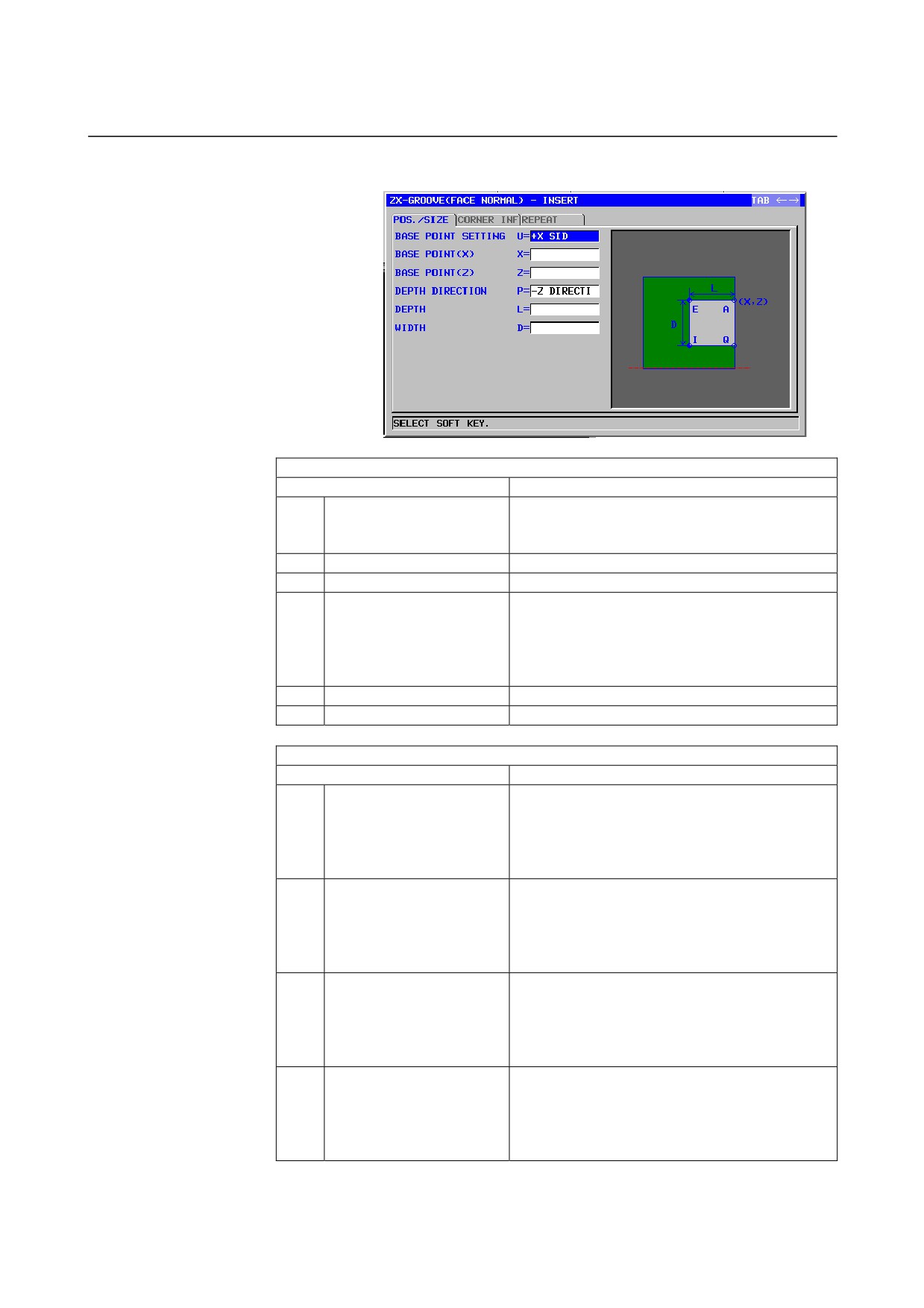
End face normal groove: G1474 (ZX plane)
POS./SIZE
Data item
Meaning
U
BASE POINT SETTING
[+X]
: Sets the base point in the +X direction.
(initial value)
[-X]
: Sets the base point in the -X direction.
X
BASE POINT (X)
X coordinate of the reference position of a groove
Z
BASE POINT (Z)
Z coordinate of the reference position of a groove
P
DEPTH DIRECTION
As to Z axis Depth direction,
[-Z]
: Depth is in the -Z direction.
[+Z]
: Depth is in the +Z direction.
Remark) This data item is enable when the
parameter No.27100#0 = 1.
L
DEPTH
Groove depth (radius value, positive value)
D
WIDTH
Groove width (radius value, positive value)
CORNER INFO
Data item
Meaning
A
CORNER TYPE-1
For corner (1) of the reference position
[NOTHIN]
: Specifies neither chamfering nor
corner rounding (initial value).
[CHAMFR] : Specifies chamfering.
[ARC]
: Specifies corner rounding.
B
CORNER SIZE
Chamfer amount or corner radius (radius value,
positive value)
Remark) This data item is indicated only when
[CHAMFR] or [ARC] is selected for
CORNER TYPE-1.
E
CORNER TYPE-2
For corner (2)
[NOTHIN]
: Specifies neither chamfering nor
corner rounding (initial value).
[CHAMFR] : Specifies chamfering.
[ARC]
: Specifies corner rounding.
F
CORNER SIZE
Chamfer amount or corner radius (radius value,
positive value)
Remark) This data item is indicated only when
[CHAMFR] or [ARC] is selected for
CORNER TYPE-2.
- 554 -
B-63874EN/05
CYCLE MACHINING TYPES
2.TURNING
CORNER INFO
Data item
Meaning
I
CORNER TYPE-3
For corner (3)
[NOTHIN]
: Specifies neither chamfering nor
corner rounding (initial value).
[CHAMFR] : Specifies chamfering.
[ARC]
: Specifies corner rounding.
J
CORNER SIZE
Chamfer amount or corner radius (radius value,
positive value)
Remark) This data item is indicated only when
[CHAMFR] or [ARC] is selected for
CORNER TYPE-3.
Q
CORNER TYPE-4
For corner (4)
[NOTHIN]
: Specifies neither chamfering nor
corner rounding (initial value).
[CHAMFR] : Specifies chamfering.
[ARC]
: Specifies corner rounding.
R
CORNER SIZE
Chamfer amount or corner radius (radius value,
positive value)
Remark) This data item is indicated only when
[CHAMFR] or [ARC] is selected for
CORNER TYPE-4.
REPEAT
Data item
Meaning
M*
GROOVE NUMBER
Number of grooves of the same figure to be
machined. The blank is regarded as 1. (positive
value)
S
PITCH
Distance between the reference positions of two
adjacent grooves (radius value, positive value)
W*
PITCH DIRECTION
[-X]
: Places a second and subsequent grooves
in the -X direction (initial value).
[+X]
: Places a second and subsequent grooves
in the +X direction.
- 555 -
2.TURNING
CYCLE MACHINING TYPES
B-63874EN/05
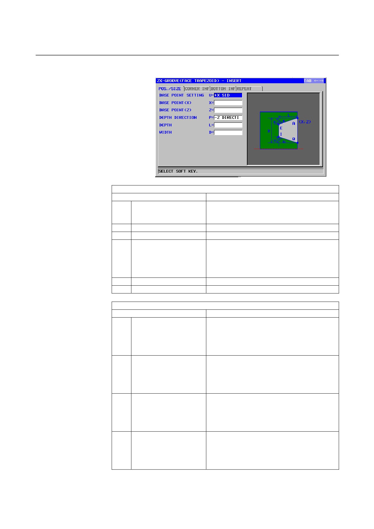
End face trapezoidal groove: G1475 (ZX plane)
POS./SIZE
Data item
Meaning
U
BASE POINT SETTING
[+X]
: Sets the base point in the +X direction.
(initial value)
[-X]
: Sets the base point in the -X direction.
X
BASE POINT (X)
X coordinate of the reference position of a groove
Z
BASE POINT (Z)
Z coordinate of the reference position of a groove
P
DEPTH DIRECTION
As to Z axis Depth direction,
[-Z]
: Depth is in the -Z direction.
[+Z]
: Depth is in the +Z direction.
Remark) This data item is enable when the
parameter No.27100#0 = 1.
L
DEPTH
Groove depth (radius value, positive value)
D
WIDTH
Groove width (radius value, positive value)
CORNER INFO
Data item
Meaning
A
CORNER TYPE-1
For corner (1) of the reference position
[NOTHIN]
: Specifies neither chamfering nor
corner rounding (initial value).
[CHAMFR] : Specifies chamfering.
[ARC]
: Specifies corner rounding.
B
CORNER SIZE
Chamfer amount or corner radius (radius value,
positive value)
Remark) This data item is indicated only when
[CHAMFR] or [ARC] is selected for
CORNER TYPE-1.
E
CORNER TYPE-2
For corner (2)
[NOTHIN]
: Specifies neither chamfering nor
corner rounding (initial value).
[CHAMFR] : Specifies chamfering.
[ARC]
: Specifies corner rounding.
F
CORNER SIZE
Chamfer amount or corner radius (radius value,
positive value)
Remark) This data item is indicated only when
[CHAMFR] or [ARC] is selected for
CORNER TYPE-2.
- 556 -
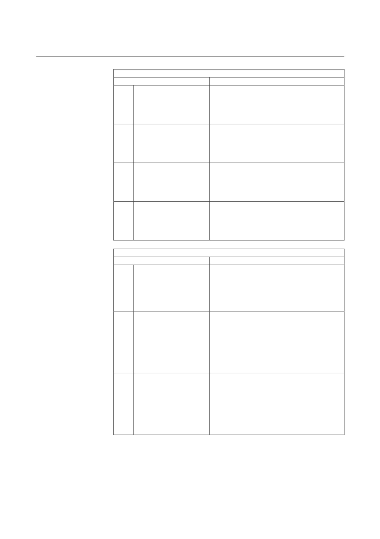
B-63874EN/05
CYCLE MACHINING TYPES
2.TURNING
CORNER INFO
Data item
Meaning
I
CORNER TYPE-3
For corner (3)
[NOTHIN]
: Specifies neither chamfering nor
corner rounding (initial value).
[CHAMFR] : Specifies chamfering.
[ARC]
: Specifies corner rounding.
J
CORNER SIZE
Chamfer amount or corner radius (radius value,
positive value)
Remark) This data item is indicated only when
[CHAMFR] or [ARC] is selected for
CORNER TYPE-3.
Q
CORNER TYPE-4
For corner (4)
[NOTHIN]
: Specifies neither chamfering nor
corner rounding (initial value).
[CHAMFR] : Specifies chamfering.
[ARC]
: Specifies corner rounding.
R
CORNER SIZE
Chamfer amount or corner radius (radius value,
positive value)
Remark) This data item is indicated only when
[CHAMFR] or [ARC] is selected for
CORNER TYPE-4.
BOTTOM INFO
Data item
Meaning
H
BOTTOM TYPE
[WIDTH] : Specifies the difference between the
groove entry of each side face and the
width of the groove bottom (initial
value).
[ANGLE]: Specifies the angle of a side face of a
groove.
K*
BOTTOM SIZE/ANGLE
Difference between the groove entry of the side
face on the reference position side and the width
of the groove bottom when [WIDTH] is specified
(radius value, positive value).
Inclination angle of the side face on the reference
position side when [ANGLE] is specified (positive
value).
The blank is regarded as 0 for both.
V*
BOTOM SIZE/ANGLE
Difference between the groove entry of the side
face on the side opposite to the reference position
side and the width of the groove bottom when
[WIDTH] is specified (radius value, positive value).
Inclination angle of the side face on the side
opposite to the reference position side when
[ANGLE] is specified (positive value).
The blank is regarded as 0 for both.
- 557 -

2.TURNING
CYCLE MACHINING TYPES
B-63874EN/05
REPEAT
Data item
Meaning
M*
GROOVE NUMBER
Number of grooves of the same figure to be
machined. The blank is regarded as 1. (positive
value)
S
PITCH
Distance between the reference positions of two
adjacent grooves (radius value, positive value)
W*
PITCH DIRECTION
[-X]
: Places a second and subsequent grooves
in the -X direction (initial value).
[+X]
: Places a second and subsequent grooves
in the +X direction.
- 558 -
B-63874EN/05
CYCLE MACHINING TYPES
2.TURNING
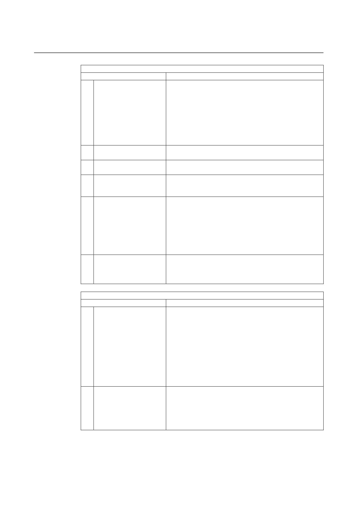
2.4
THREADING
2.4.1
Machining Type Blocks for Threading
External: G1140
Internal: G1141
TOOL COND.
Data item
Meaning
R
NOSE RADIUS
Tool nose radius of a threading tool. (positive value)
A
NOSE ANGLE
Tool angle of a threading tool (positive value)
J
IMAGINARY TOOL NOSE
Imaginary tool nose position of a threading tool.
NOTE
1 Tab ‘TOOL COND.’ is enabled when bit 0 (TLG) of
parameter No. 27102 = 1.
2 The operator ordinarily sets the above data on the
tab of ‘TOOL DATA’ in Tool Offset window.
Therefore, it is not necessary to display the tab
‘TOOL COND.’
- 559 -
2.TURNING
CYCLE MACHINING TYPES
B-63874EN/05
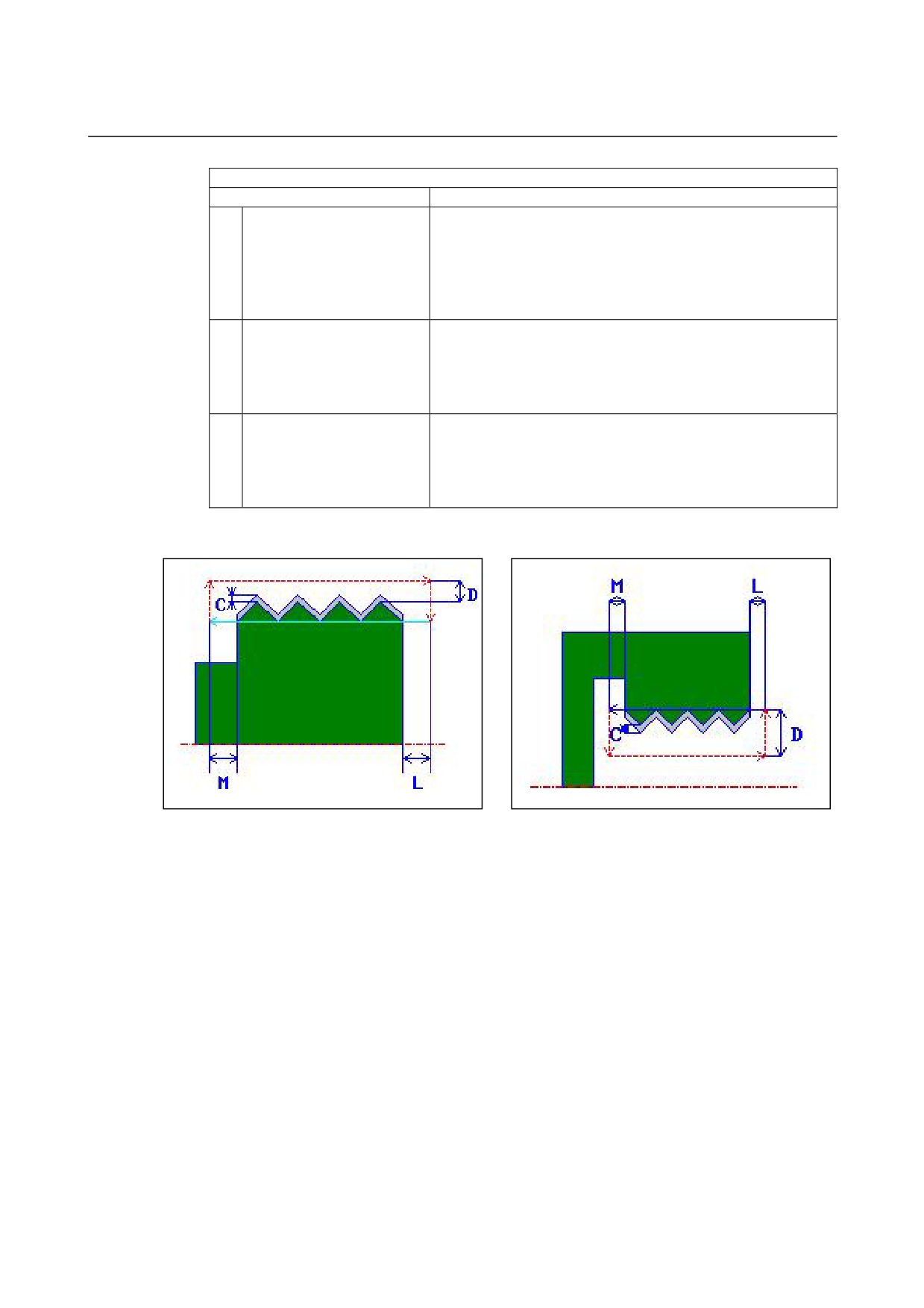
CUT COND.
Data item
Meaning
W
CUTTING METHOD
[SING.A]
: Constant amount of cut, one-edge cutting
[BOTH A] : Constant amount of cut, both-edge cutting
[STAG.A] : Constant amount of cut, both-edge zigzag thread
cutting
[SING.D]
: Constant depth of cut, one-edge cutting
[BOTH D] : Constant depth of cut, both-edge cutting
[STAG.D] : Constant depth of cut, both-edge zigzag thread
cutting
(COPY)
C*
FINISH AMOUNT
Finishing allowance for threading in the X-axis direction. The
blank is regarded as 0. (radius value, positive value)
K*
NUMBER OF FINISHING
Number of finishing operations.
(positive value)
(COPY)
S
CUT TYPE
[NUMBER] : Specifies threading by the number of cuts.
[DEPTH]
: Specifies threading by the first amount of cut.
(COPY)
P
CUT DEPTH NUMBER
Number of cuts for rough threading (999 max., positive value)
Remark) The number of finishing cuts is not included. In the
case of both-edge zigzag thread cutting, be sure to
specify an even number of cuts. If an odd number of
cuts are specified, only one additional both-edge
zigzag thread cutting operation is performed. This
data item is indicated only when [NUMBER] is
selected.
Q
CUT DEPTH
Depth of cut per rough threading operation (radius value,
positive value)
Remark) The number of cuts is determined by the depth of cut
and the cutting method.
DETAIL
Data item
Meaning
Z
APROCH MOTION
[Z→X]
: From the current position to the machining start
point, the tool moves in the Z-axis direction and
then in the X-axis direction. (Initial value for
external thread)
[X→Z]
: From the current position to the machining start
point, the tool moves in the Z-axis direction and
then in the X-axis direction. (Initial value for
internal thread)
[2 AXES]
: From the current position to the machining start
point, the tool moves simultaneously in the X- and
Z-axis directions.
D
SURFACE CLEARANCE
Distance between a thread crest and machining start point
(approach point) in the X-axis direction (radius value, positive
value)
Remark) By referring to the parameter No. 27156 (minimum
clamp value), the system sets the data as an initial
value.
- 560 -
B-63874EN/05
CYCLE MACHINING TYPES
2.TURNING
DETAIL
Data item
Meaning
L
ENTRANCE CLEARANCE
Distance between a thread start point and machining start point
(approach point) in the Z-axis direction (radius value, positive
value)
Remark) By referring to the parameter No. 27157 (minimum
clamp value), the system sets the data as an initial
value.
M
EXIT CLERANCE
Distance between a thread end point and threading operation
end point in the Z-axis direction. (radius value, positive value)
Remark) By referring to the parameter No. 27158 (minimum
clamp value), the system sets the data as an initial
value.
Y
CUT DEPTH DIRECTION
As to X axis Cut direction,
[-X]
: Cuts in the -X direction.
[+X]
: Cuts in the +X direction.
Remark) This data item is enable when the parameter
No.27100#0 = 1.
(COPY)
• Tool path
External-thread cutting
Internal-thread cutting
<1> The tool moves to the position "thread start point
+ thread
surface clearance (D in the X-axis direction)" and position thread
entry clearance (L in the Z-axis direction) by rapid traverse.
<2> Threading is performed using a specified cutting method. The
end point of threading in the Z-axis direction is the thread exit
clearance apart from the thread end point.
<3> If
[NUMBER] is specified as a cut-in type, threading is
performed as many times as the [NUMBER] value. If [DEPTH]
is specified, this amount is used in the first cut-in and threading
is performed until the specified thread figure is obtained.
<4> After all portions are cut, the tool moves to the position "cut-in
start position + clearance (L)" in the X-axis direction at the rapid
traverse rate.
- 561 -
2.TURNING
CYCLE MACHINING TYPES
B-63874EN/05
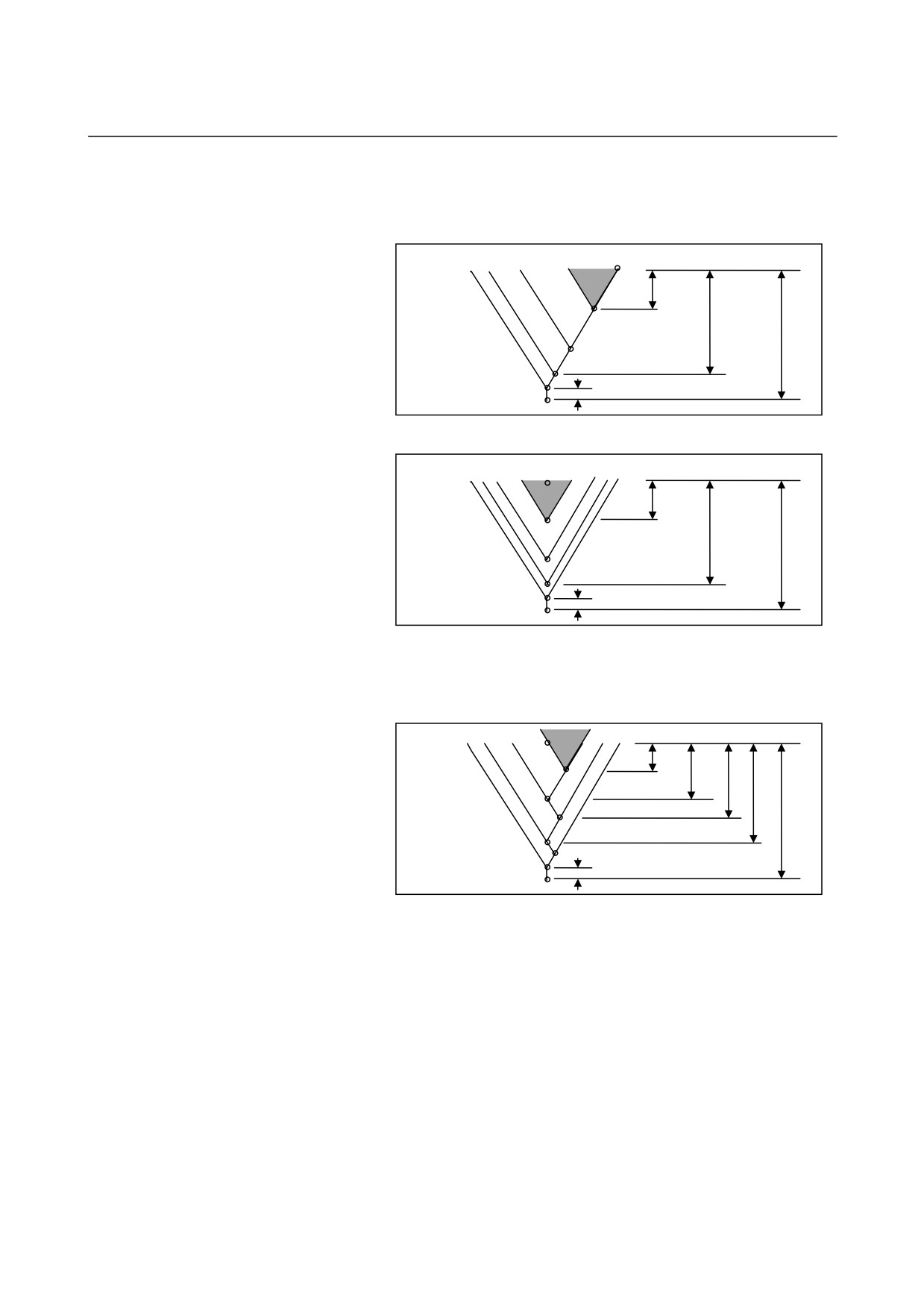
- See the following expansions for details of the cutting methods.
[SING.A]
: Constant amount of cut, one-edge cutting
d1=D
dn=
Dsqrt(n)
H
u
[BOTH A]
: Constant amount of cut, both-edge cutting
d1=D
dn=
Dsqrt(n)
H
u
H=Height of thread crest, D=Amount of cut, u=Finishing allowance
[STAG.A]
: Constant amount of cut, both-edge zigzag thread cutting
d1=D
dn-2
dn-1
dn
H
u
dn-2 = D sqrt(n-2)
dn-1 = (D(sqrt(n-2) + sqrt(n)))/2
dn = D sqrt(n)
When the amount of cut is smaller than the minimum amount of cut
(parameter No. 27145), the amount of cut is clamped to the minimum
amount of cut.
- 562 -
B-63874EN/05
CYCLE MACHINING TYPES
2.TURNING
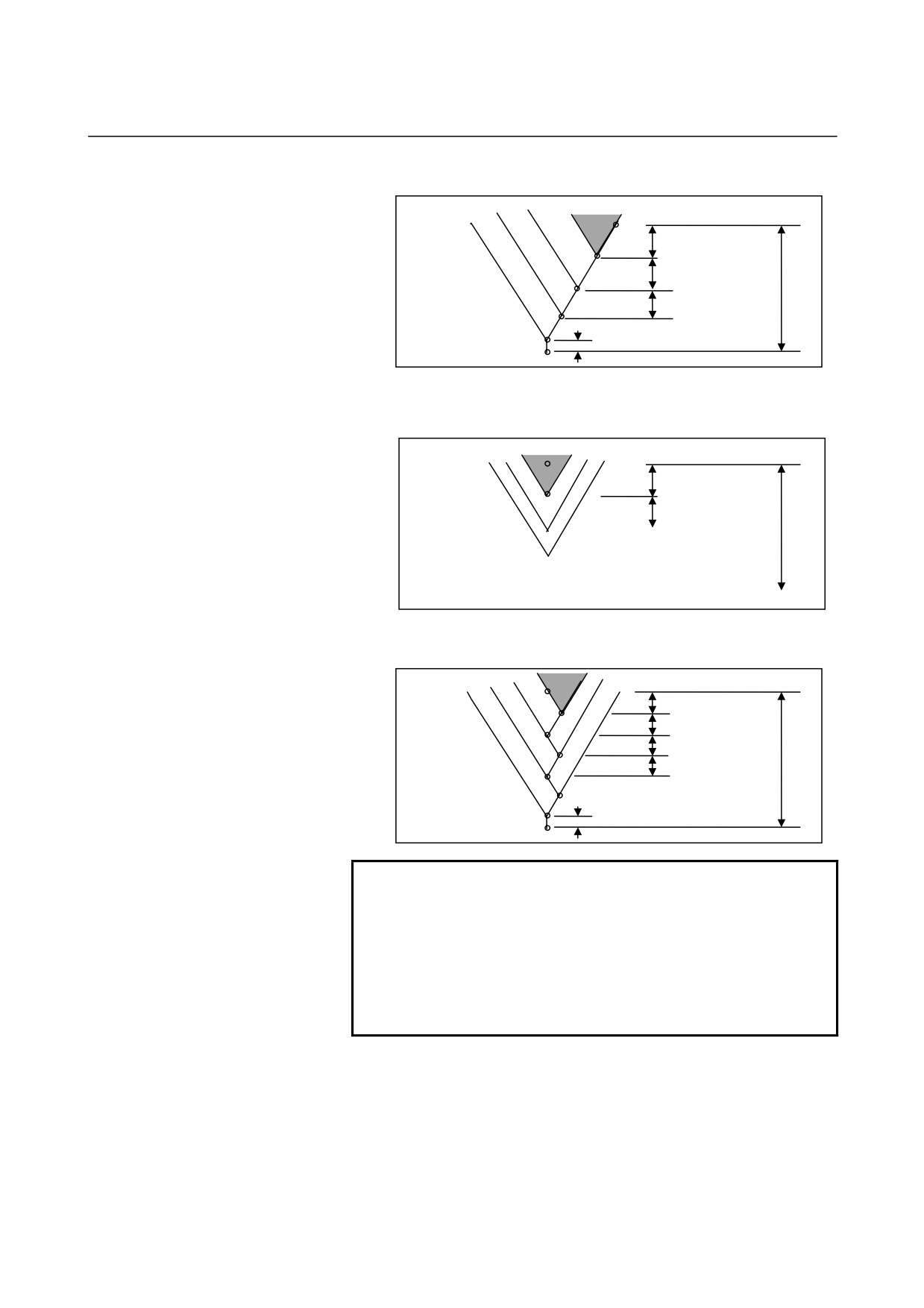
[SING.D]
: Constant depth of cut, one-edge cutting
D
D
H
D
u
[BOTH D]
: Constant depth of cut, both-edge cutting
D
D
[STAG.D]
: Constant depth of cut, both-edge zigzag thread cutting
D
D
D
H
D
u
NOTE
Depending on the minimum amount of cut, the
specified number of cuts may be excessive. In
such a case, threading is performed by a number
of cuts less than the specified number of cuts.
The number of cuts actually done may differ from
the specified number of cuts due to a calculation
error.
- 563 -
2.TURNING
CYCLE MACHINING TYPES
B-63874EN/05
2.4.2
Fixed Form Figure Blocks for Threading
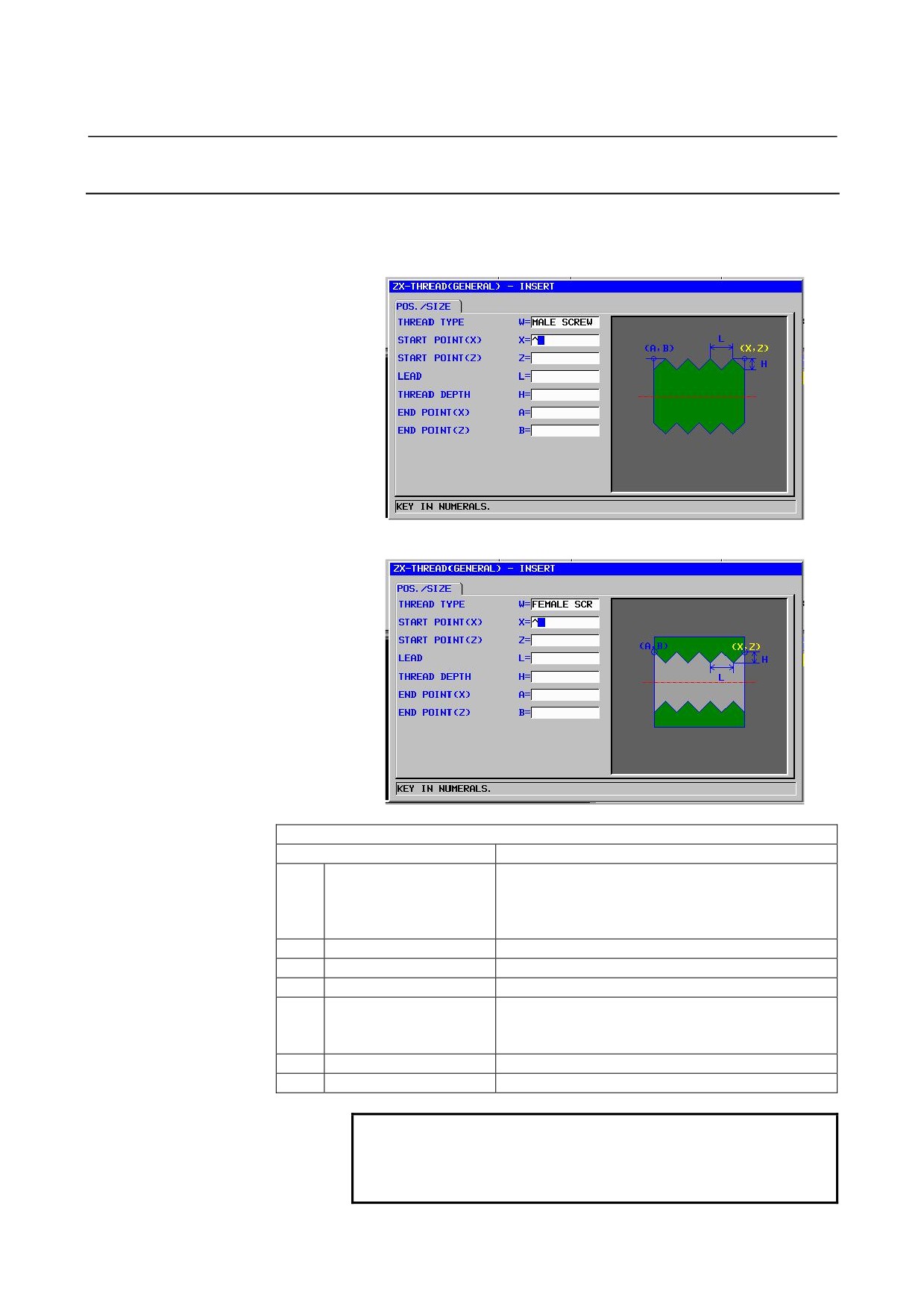
General-purpose thread: G1460 (ZX plane)
Male screw)
Female screw)
POS./SIZE
Data item
Meaning
W
THREAD TYPE
[MALE]
: To be selected when the external
thread is specified as threading type
[FEMALE] : To be selected when the internal thread
is specified as threading type
X
START POINT (X)
X coordinate of a thread start point
Z
START POINT (Z)
Z coordinate of a thread start point
L
LEAD
Thread lead (radius value, positive value)
H
THREAD DEPTH
Thread depth (radius value, positive value)
Remark) A thread depth is automatically calculated
by pressing [CALC] after inputting a lead.
A
END POINT (X)
X coordinate of a thread end point
B
END POINT (Z)
Z coordinate of a thread end point
NOTE
The thread depth of a general-purpose thread is
calculated from parameter No. 27150 (external) or
parameter No. 27151 (internal) and a thread lead.
- 564 -
B-63874EN/05
CYCLE MACHINING TYPES
2.TURNING
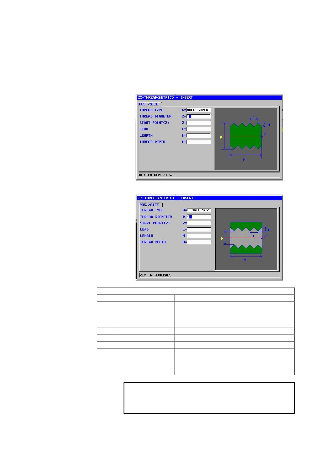
Metric thread: G1461 (ZX plane)
A metric thread is cut. Only one straight thread is machined. Be sure to
set a tool angle of 60 degrees.
Male screw)
Female screw)
POS./SIZE
Data item
Meaning
W
THREAD TYPE
[MALE]
: To be selected when the external
thread is specified as threading type
[FEMALE] : To be selected when the internal thread
is specified as threading type
D
THREAD DIAMETER
Thread diameter (positive value)
Z
START POINT (Z)
Z coordinate of a thread start point
L
LEAD
Thread lead (radius value, positive value)
M
LENGTH
Thread length (radius value, positive value)
H
THREAD DEPTH
Thread depth (radius value, positive value)
Remark) A thread depth is automatically calculated
by pressing [CALC] after inputting a lead.
NOTE
The thread depth of a metric thread is calculated
from parameter No. 27152 (external) or parameter
No. 27153 (internal) and a thread lead.
- 565 -
2.TURNING
CYCLE MACHINING TYPES
B-63874EN/05
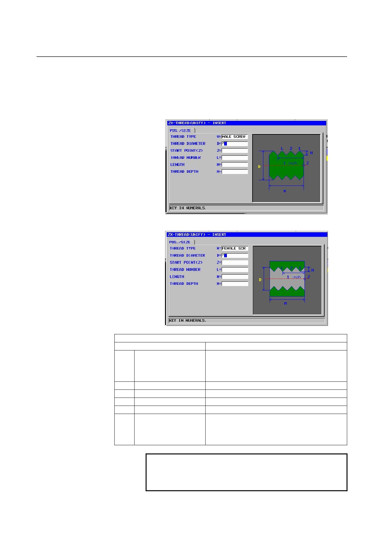
Unified thread: G1462 (ZX plane)
A unified thread is cut. Only one straight thread is machined. For a
unified thread, the "number of thread crests/inch" is used instead of a
thread lead. Be sure to set a tool angle of 60 degrees.
Male screw)
Female screw)
POS./SIZE
Data item
Meaning
W
THREAD TYPE
[MALE]
: To be selected when the external
thread is specified as threading type
[FEMALE] : To be selected when the internal thread
is specified as threading type
D
THREAD DIAMETER
Thread diameter (positive value)
Z
START POINT (Z)
Z coordinate of a thread start point
L
THREAD NUMBER
Number of thread crests per inch
M
LENGTH
Thread length (radius value, positive value)
H
THREAD DEPTH
Thread depth (radius value, positive value)
Remark) A thread depth is automatically calculated
by pressing [CALC] after inputting a thread
number.
NOTE
The thread depth of a unified thread is calculated
from parameter No. 27152 (external) or parameter
No. 27153 (internal) and a thread number.
- 566 -
B-63874EN/05
CYCLE MACHINING TYPES
2.TURNING
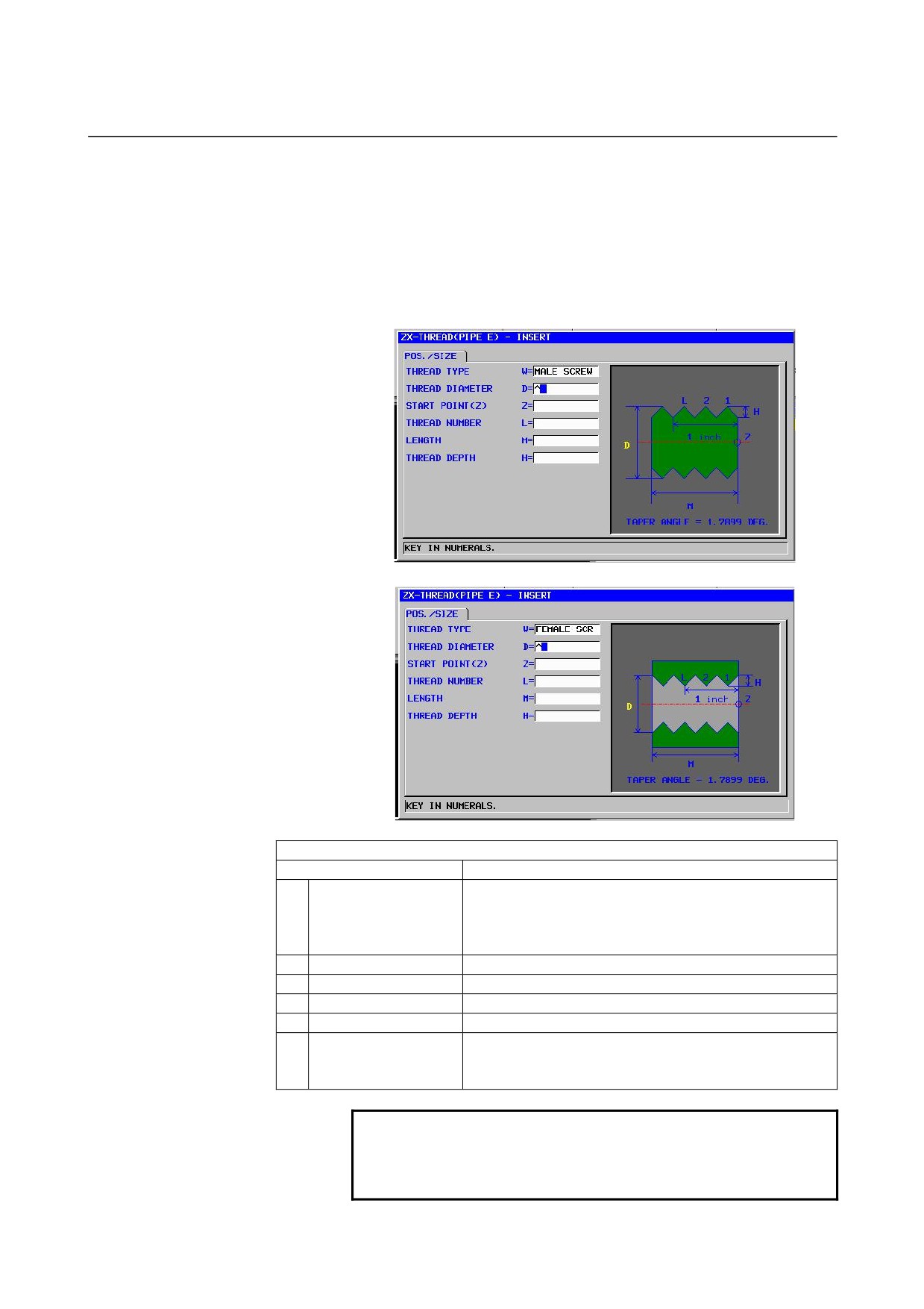
PT thread: G1463 (tapered thread for tubes, ZX plane)
A PT thread (tapered thread for tubes) is cut. Only one tapered thread
(tapered by 1.7899 degrees) is machined. Be sure to set a tool angle of 55
degrees. The taper figure of an external thread (male thread) is such that
the end face of a blank represents a minor diameter portion. The taper
figure of an internal thread (female thread) is such that the end face of a
blank represents a major diameter portion.
Male screw)
Female screw)
POS./SIZE
Data item
Meaning
W
THREAD TYPE
[MALE]
: To be selected when the external thread is
specified as threading type
[FEMALE] : To be selected when the internal thread is
specified as threading type
D
THREAD DIAMETER
Thread diameter (positive value)
Z
START POINT (Z)
Z coordinate of a thread start point
L
THREAD NUMBER
Number of thread crests per inch
M
LENGTH
Thread length (radius value, positive value)
H
THREAD DEPTH
Thread depth (radius value, positive value)
Remark) A thread depth is automatically calculated by
pressing [CALC] after inputting a thread number.
NOTE
The thread depth of a PT thread is calculated from
parameter No. 27154 (external) or parameter No.
27155 (internal) and a thread number.
- 567 -
2.TURNING
CYCLE MACHINING TYPES
B-63874EN/05
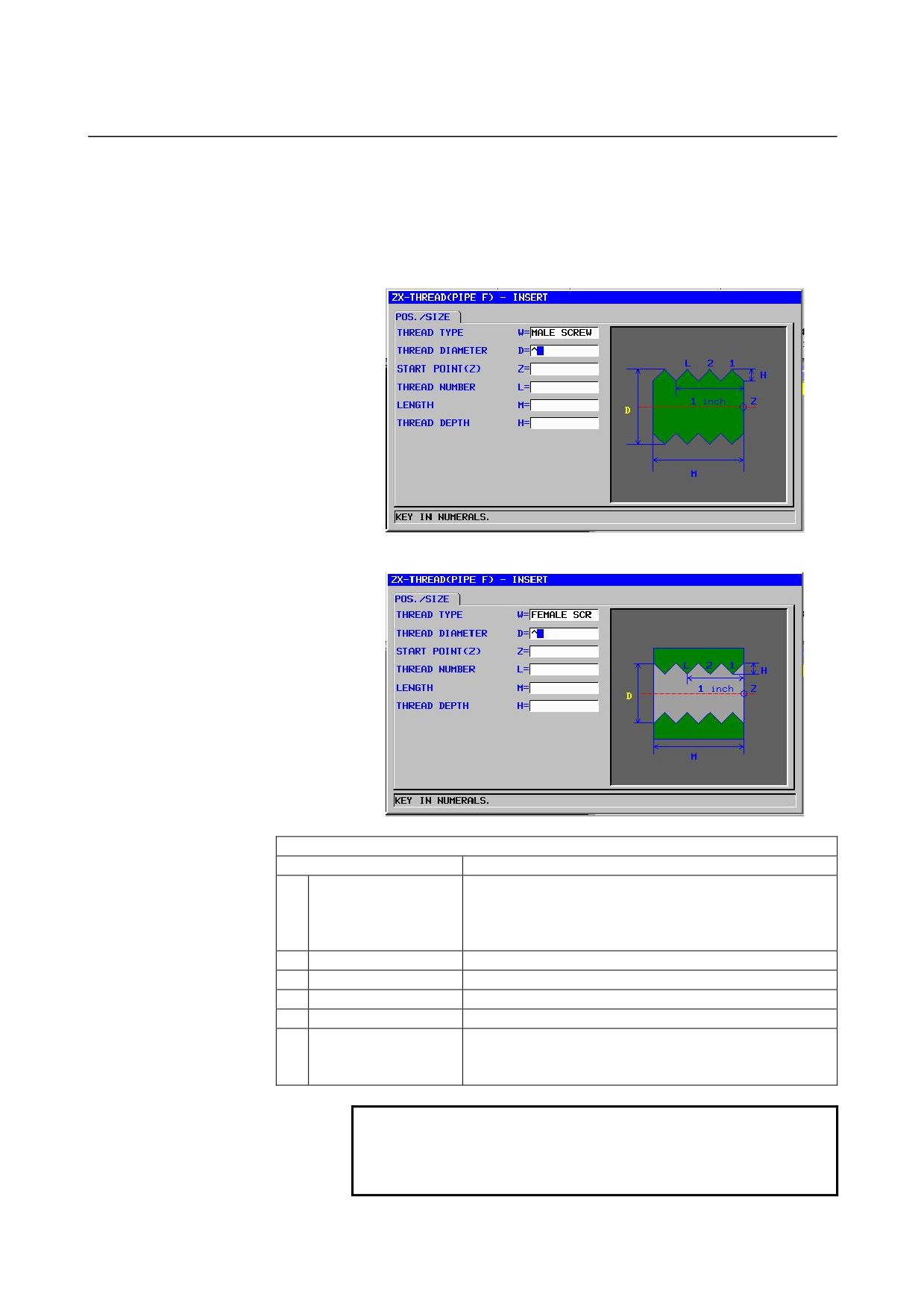
PF thread: G1464 (parallel thread for tubes, ZX plane)
A PF thread (parallel thread for tubes) is cut. Only one straight thread is
machined. Be sure to set a tool angle of 55 degrees.
Male screw)
Female screw)
POS./SIZE
Data item
Meaning
W
THREAD TYPE
[MALE]
: To be selected when the external thread is
specified as threading type
[FEMALE] : To be selected when the internal thread is
specified as threading type
D
THREAD DIAMETER
Thread diameter (positive value)
Z
START POINT (Z)
Z coordinate of a thread start point
L
THREAD NUMBER
Number of thread crests per inch
M
LENGTH
Thread length (radius value, positive value)
H
THREAD DEPTH
Thread depth (radius value, positive value)
Remark) A thread depth is automatically calculated by
pressing [CALC] after inputting a thread number.
NOTE
The thread depth of a PF thread is calculated from
parameter No. 27154 (external) or parameter No.
27155 (internal) and a thread number.
- 568 -
B-63874EN/05
CYCLE MACHINING TYPES
2.TURNING
2.5
REAR END FACING BY TURNING
2.5.1
Rear End Facing
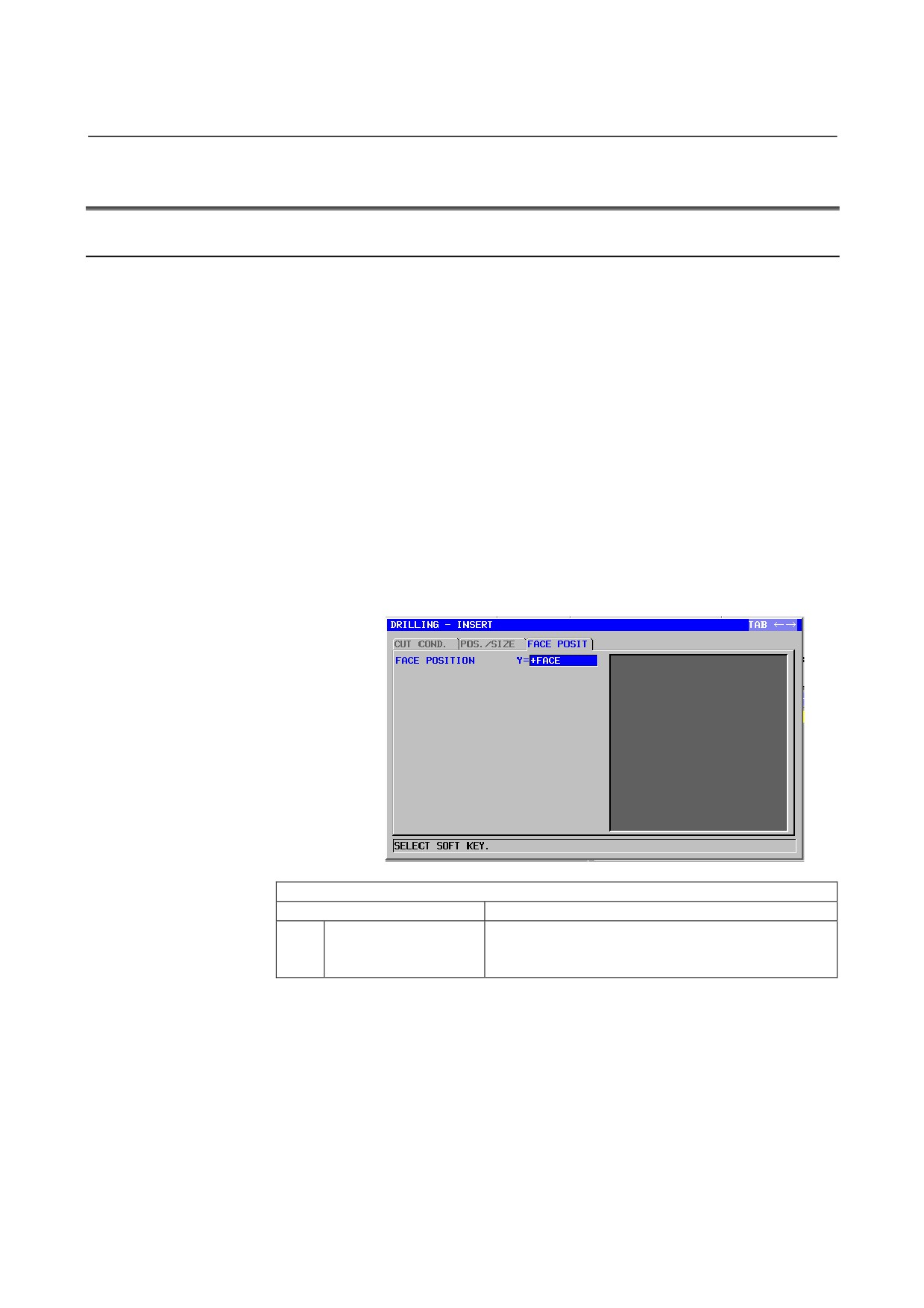
By setting bit 4 of parameter No. 27100 to 1, the input item "FACE
POSITION" is displayed on the following menu. By entering this data,
rear end facing is enabled.
1. Hole machining - Center drilling : G1100
2. Hole machining - Drilling : G1101
3. Hole machining - Tapping : G1102
4. Hole machining - Reaming : G1103
5. Hole machining - Boring : G1104
6. Turning - End face roughing : G1122
7. Turning - End face semifinishing : G1125
8. Turning - End face finishing : G1128
9. Turning groove - End face roughing : G1132
10. Turning groove - End face roughing and finishing : G1135
11. Turning groove - End face finishing : G1138
Example) Drilling : G1101
FACE POSIT
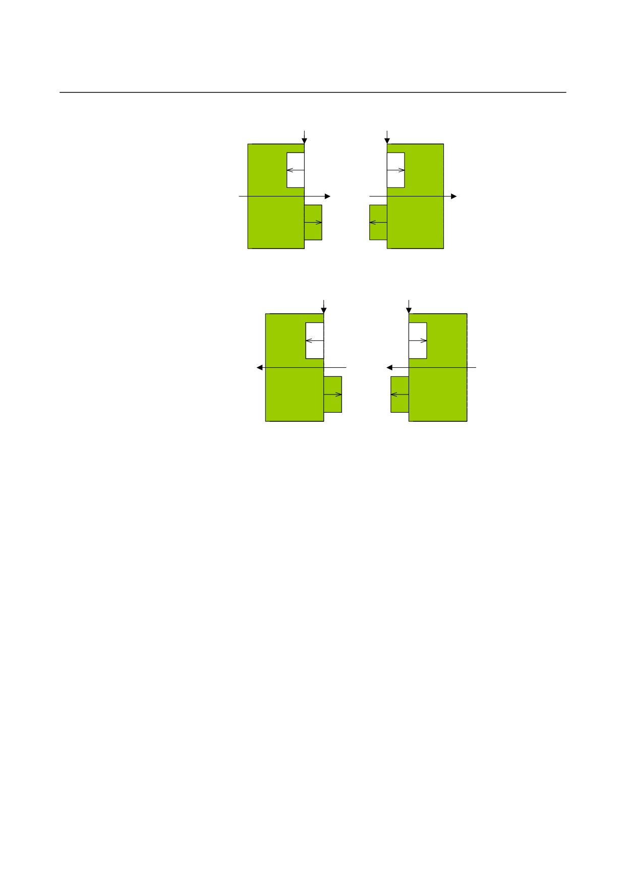
Data item
Meaning
Y
FACE POSITION
[+FACE ]: References the figure below (+ end face).
(initial value)
[-FACE ]: References the figure below (- end face).
- 569 -
2.TURNING
CYCLE MACHINING TYPES
B-63874EN/05
Reference position
Reference position
(-)
Depth
Depth
(-)
+Z
+Z
(+)
Height
Height
(+)
+end face
- end face
Reference position
Reference position
(-)
Depth
Depth
(-)
+Z
+Z
(+)
Height
Height
(+)
- end face
+ end face
- 570 -

B-63874EN/05
CYCLE MACHINING TYPES 3.SLANT FACE MACHINING (COORDINATE CONVERSION)
3
SLANT FACE MACHINING
(COORDINATE CONVERSION)
NOTE
To use slant face machining with MANUAL GUIDE
i, the option for the three-dimensional coordinate
conversion function is required.
For details, refer to the relevant manual issued by
the machine tool builder.
- 571 -
3.SLANT FACE MACHINING (COORDINATE CONVERSION) CYCLE MACHINING TYPES B-63874EN/05
3.1
SUPPORTABLE MACHINE CONFIGURATION
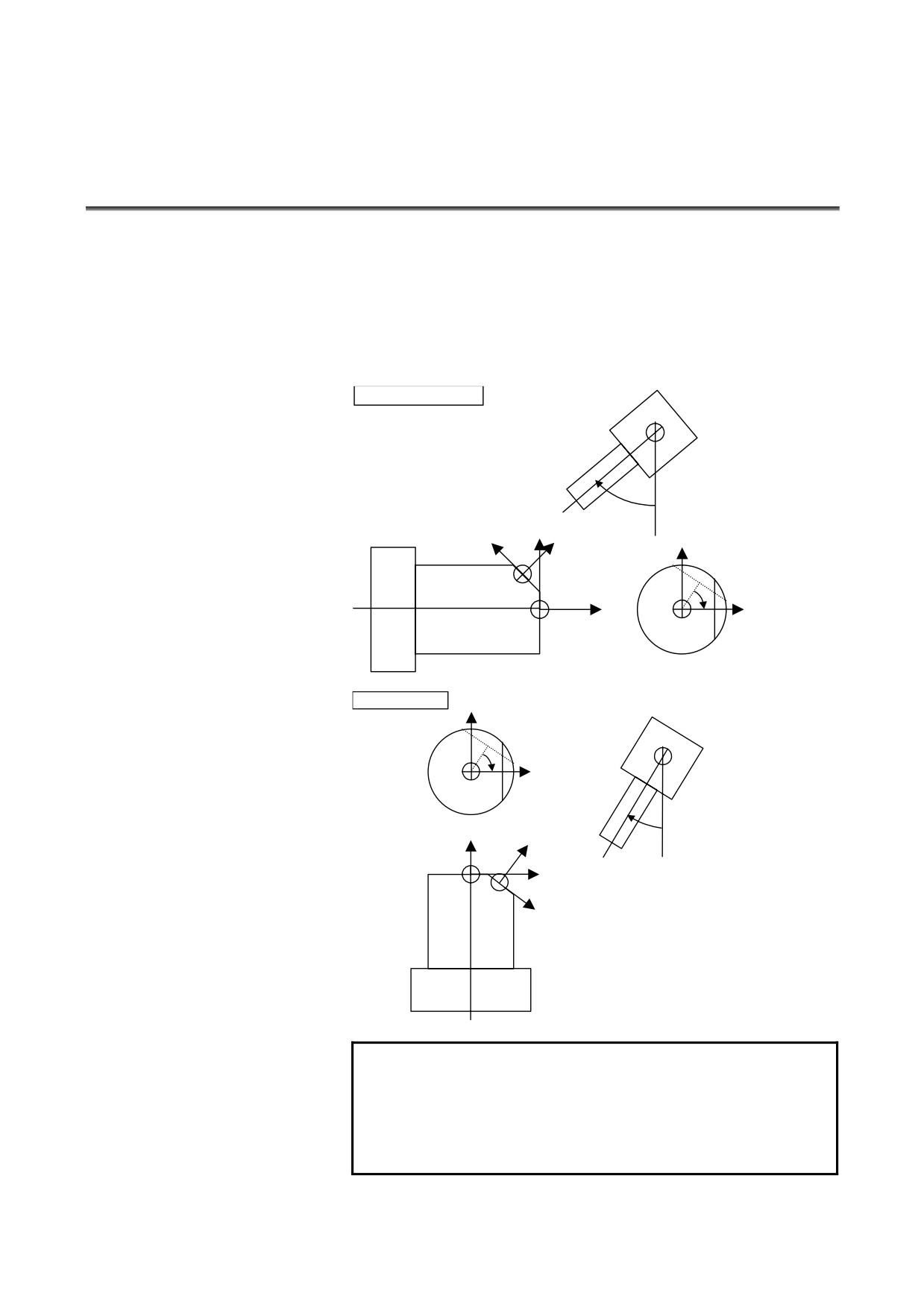
With MANUAL GUIDE i, slant face machining, which is a mixture of
table rotation and tool rotation, can be specified.
Those parameters that support a machine configuration used must be set
beforehand.
(1) Mixture type
This type of machining machines a slant face by workpiece
rotation and tool rotation.
Horizontal type
Tool
B
X
X’
Y
Z’
Z
X
C
Workpiece
Vertical type
Y
X
C
Tool
Z
B
Z’
X
X’
Workpiece
NOTE
It is assumed that the C-axis rotates about the
Z-axis, and the rotation center is on the Z-axis.
Moreover, it is assumed that the B-axis rotates
about the Y-axis, and the rotation center is on the
Y-axis.
- 572 -
B-63874EN/05
CYCLE MACHINING TYPES 3.SLANT FACE MACHINING (COORDINATE CONVERSION)
3.2
SLANT FACE MACHINING COMMAND (COORDINATE
CONVERSION)
When slant face machining is performed with MANUAL GUIDE i, a
slant face to be machined must be first specified with the coordinate
conversion command, then a machining program for milling to be
performed must be input.
Upon completion of slant face machining, coordinate conversion
cancellation must be specified.
NOTE
Slant face machining can be performed with the
following types of milling (all on the XY plane):
1. Hole machining
2. Facing
3. Contouring
4. Pocketing
5. Grooving
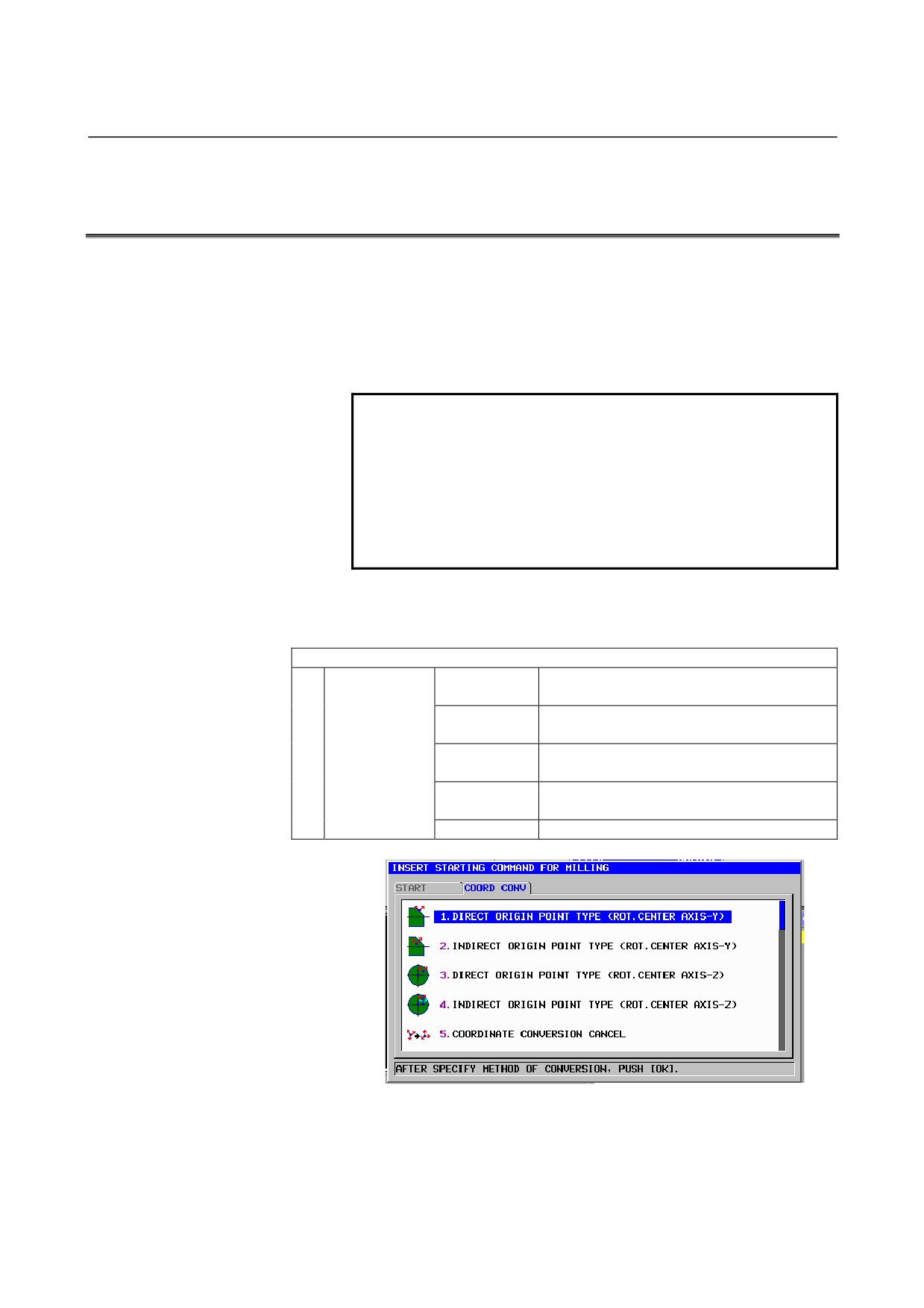
With MANUAL GUIDE i, the G code commands listed below are
available to enable coordinate conversion for slant face machining.
Coordinate conversion
G1952
Direct origin specification (with the rotation
center on the Y-axis)
G1953
Indirect origin specification (with the rotation
center on the Y-axis)
Command
G1954
Direct origin specification (with the rotation
block
center on the Z-axis)
G1955
Indirect origin specification (with the rotation
center on the Z-axis)
G1959
Coordinate conversion cancel
- 573 -
3.SLANT FACE MACHINING (COORDINATE CONVERSION) CYCLE MACHINING TYPES B-63874EN/05
NOTE
G code for coordinate conversion can be selected
from the "COORDINATE CONVERSION" tab on
the milling start command menu (displayed by
pressing [START] on the milling menu).
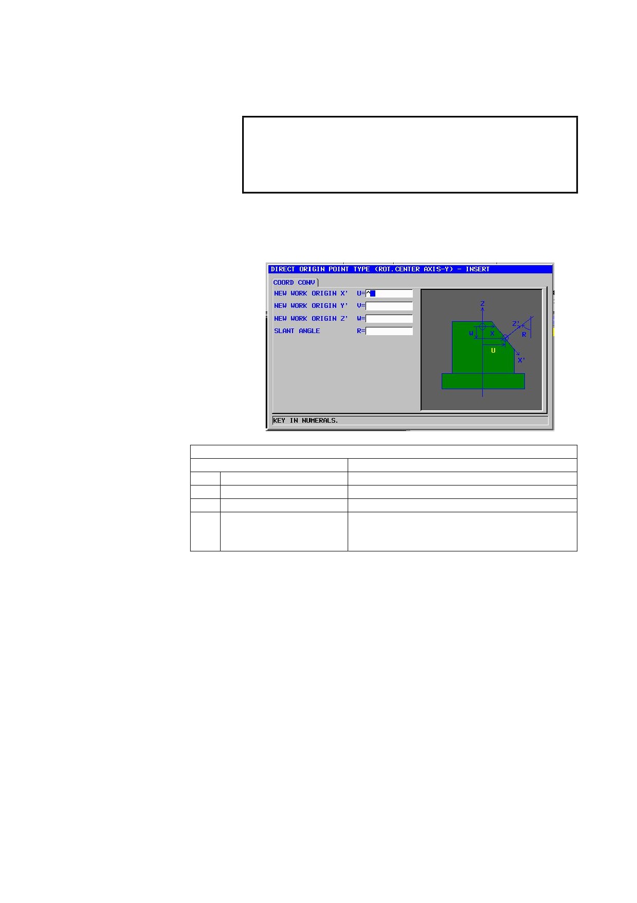
Direct origin specification (with the rotation center on the Y-axis): G1952
A machining surface rotates about the point (reference point) that serves
as the new workpiece origin of the slant face.
COORD CONVERSION
Data item
Meaning
U
NEW WORK ORIGIN X’
X coordinate of the workpiece origin of a slant face
V
NEW WORK ORIGIN Y’
Y coordinate of the workpiece origin of a slant face
W
NEW WORK ORIGIN Z’
Z coordinate of the workpiece origin of a slant face
R
SLANT ANGLE
Signed angle relative to the Z-axis. The CW
direction viewed from the plus direction of the
rotation axis is positive. (-90≤R≤90).
- 574 -
B-63874EN/05
CYCLE MACHINING TYPES 3.SLANT FACE MACHINING (COORDINATE CONVERSION)
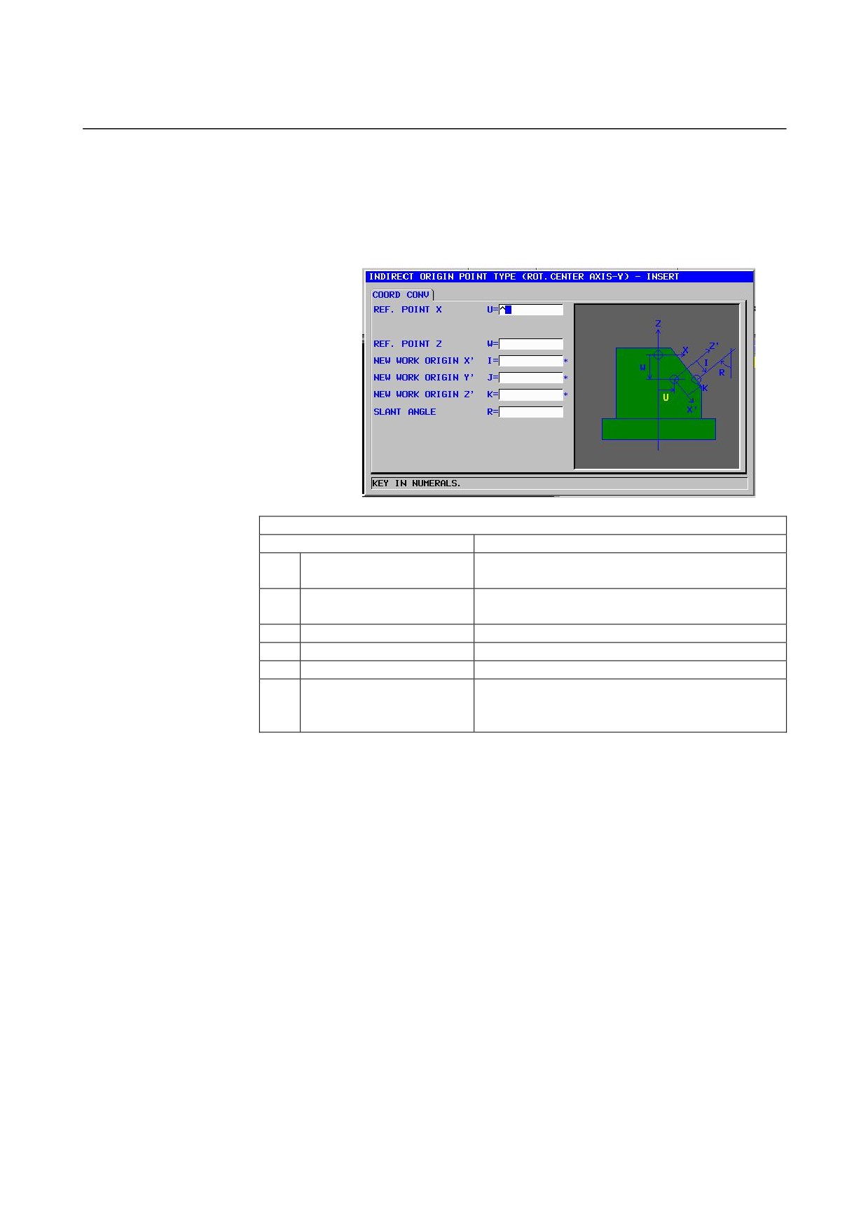
Indirect origin specification (with the rotation center on the Y-axis): G1953
A machining surface rotates about a specified reference point, and the
workpiece origin of a slant face, that is, a new machining surface, is to be
specified based on the distance from the reference point
(positive/negative value).
COORD CONVERSION
Data item
Meaning
U
REF. POINT X
X coordinate of a reference point (workpiece
coordinate system before rotation)
W
REF. POINT Z
Z coordinate of a reference point (workpiece
coordinate system before rotation)
I
NEW WORK ORIGIN X’
X coordinate of the workpiece origin of a slant face
J
NEW WORK ORIGIN Y’
Y coordinate of the workpiece origin of a slant face
K
NEW WORK ORIGIN Z’
Z coordinate of the workpiece origin of a slant face
R
SLANT ANGLE
Signed angle relative to the Z-axis. The CW
direction viewed from the plus direction of the
rotation axis is positive. (-90≤R≤90).
- 575 -
3.SLANT FACE MACHINING (COORDINATE CONVERSION) CYCLE MACHINING TYPES B-63874EN/05
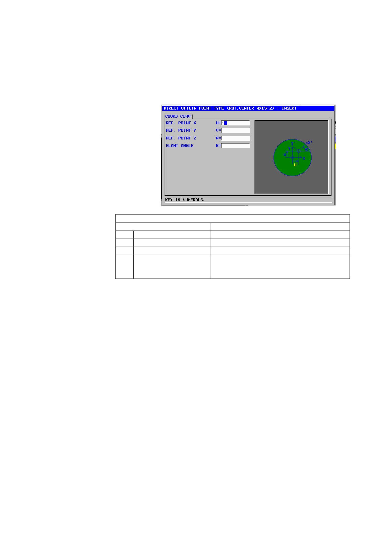
Direct origin specification (with the rotation center on the Z-axis): G1954
The machining plane rotates about the new point (reference point) that
is to become the workpiece origin of the XY plane.
COORD CONVERSION
Data item
Meaning
U
REF. POINT X
X coordinate of a new workpiece origin
V
REF. POINT Y
Y coordinate of a new workpiece origin
W
REF. POINT Z
Z coordinate of a new workpiece origin
R
SLANT ANGLE
Signed angle with respect to the X-axis. The CW
direction viewed from the plus rotation axis
direction is positive (-90 ≤ R ≤ 90).
- 576 -
B-63874EN/05
CYCLE MACHINING TYPES 3.SLANT FACE MACHINING (COORDINATE CONVERSION)
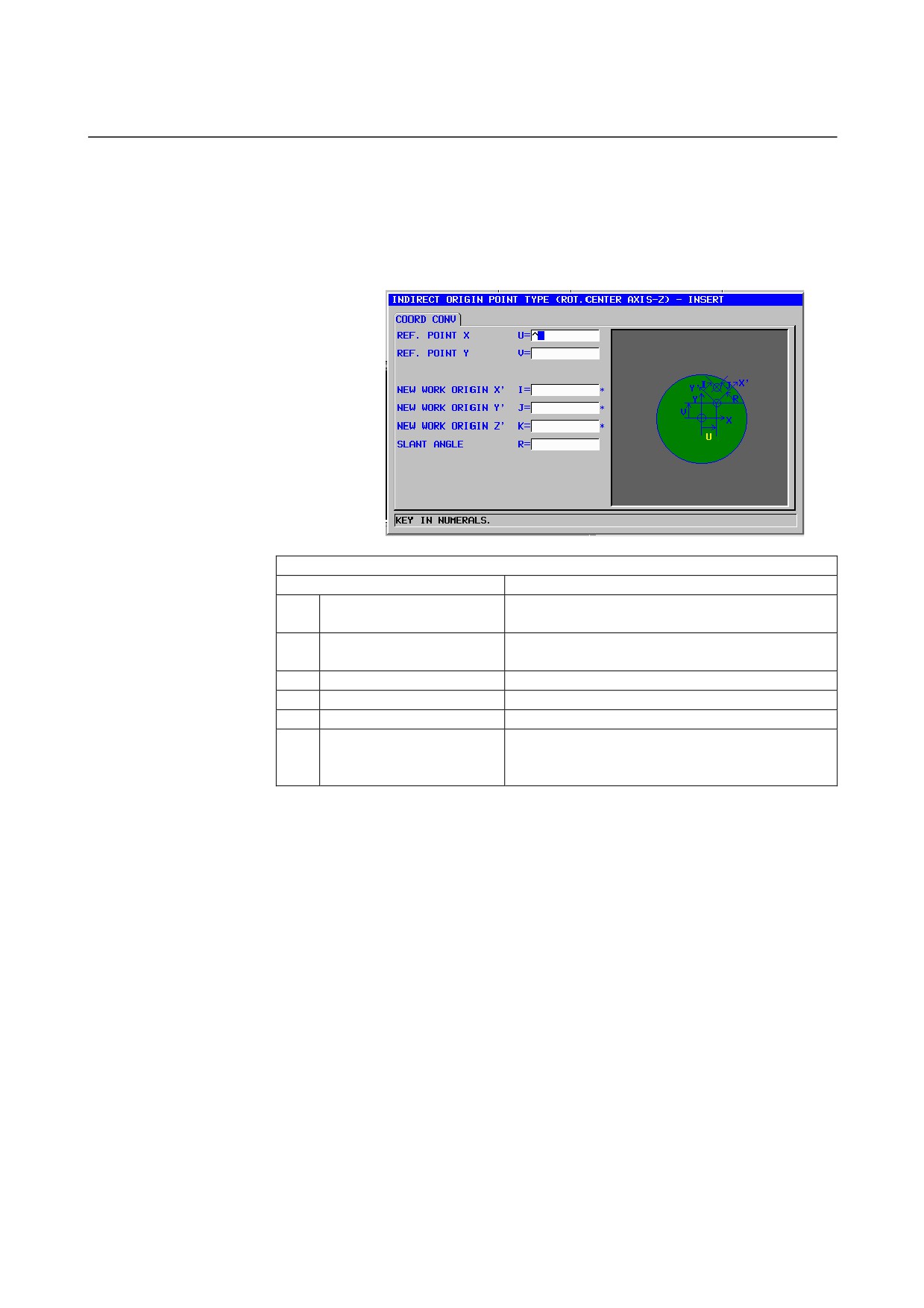
Indirect origin specification (with the rotation center on the Z-axis): G1955
The machining plane rotates about a specified reference point. Define
the workpiece origin of the XY plane, which is a new machining plane,
by specifying the distance (positive/negative value) from the reference
point.
COORD CONVERSION
Data item
Meaning
U
REF. POINT X
X coordinate of a reference point (workpiece
coordinate system before rotation)
W
REF. POINT Y
Y coordinate of a reference point (workpiece
coordinate system before rotation)
I
NEW WORK ORIGIN X’
X coordinate of the workpiece origin of the slant
J
NEW WORK ORIGIN Y’
Y coordinate of the workpiece origin of the slant
K
NEW WORK ORIGIN Z’
Z coordinate of the workpiece origin of the slant
R
SLANT ANGLE
Signed angle with respect to the Z-axis. The CW
direction viewed from the plus rotation axis
direction is positive (-90 ≤ R ≤ 90).
- 577 -
3.SLANT FACE MACHINING (COORDINATE CONVERSION) CYCLE MACHINING TYPES B-63874EN/05
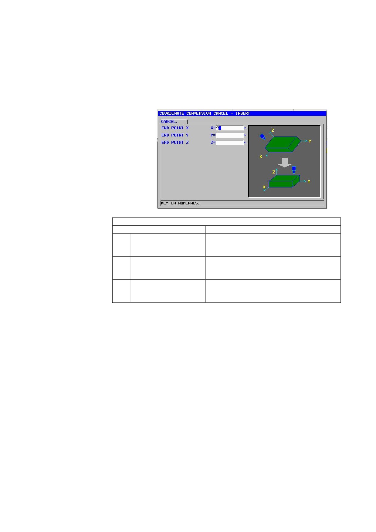
Coordinate conversion cancel: G1959
After coordinate conversion is canceled, the tool moves to the entered
end point by rapid traverse. If no end point is specified, the tool will
not move.
CANCEL
Data item
Meaning
X*
END POINT X
X coordinate to which the tool is to move by rapid
traverse after coordinate conversion is canceled. If
this data is omitted, the tool will not move.
Y*
END POINT Y
Y coordinate to which the tool is to move by rapid
traverse after coordinate conversion is canceled. If
this data is omitted, the tool will not move.
Z*
END POINT Z
Z coordinate to which the tool is to move by rapid
traverse after coordinate conversion is canceled. If
this data is omitted, the tool will not move.
- 578 -
IV. MULTI-PATH LATHE FUNCTIONS
(FOR Series 16i/18i/21i ONLY)
B-63874EN/04
MULTI-PATH LATHE FUNCTIONS
1.MULTI-PATH LATHE APPLICATION
1
MULTI-PATH LATHE APPLICATION
•
The multi-path lathe option is required in this function.
•
This function corresponds to the following CNC control units.
2 CPU - 2-path lathe CNC , 2CPU - 3-path lathe CNC
NOTE
1 The multi-path lathe function is not supported for
the Series 30i.
2 The SET-UP Guidance function or the Tool
Management function is unsupported in this
function.
3 This function cannot be used with the MANUAL
GUIDE i simulator for the personal computer.
- 581 -