FANUC MANUAL GUIDE i. OPERATOR’S MANUAL - page 18
2.TURNING
CYCLE MACHINING TYPES
B-63874EN/05
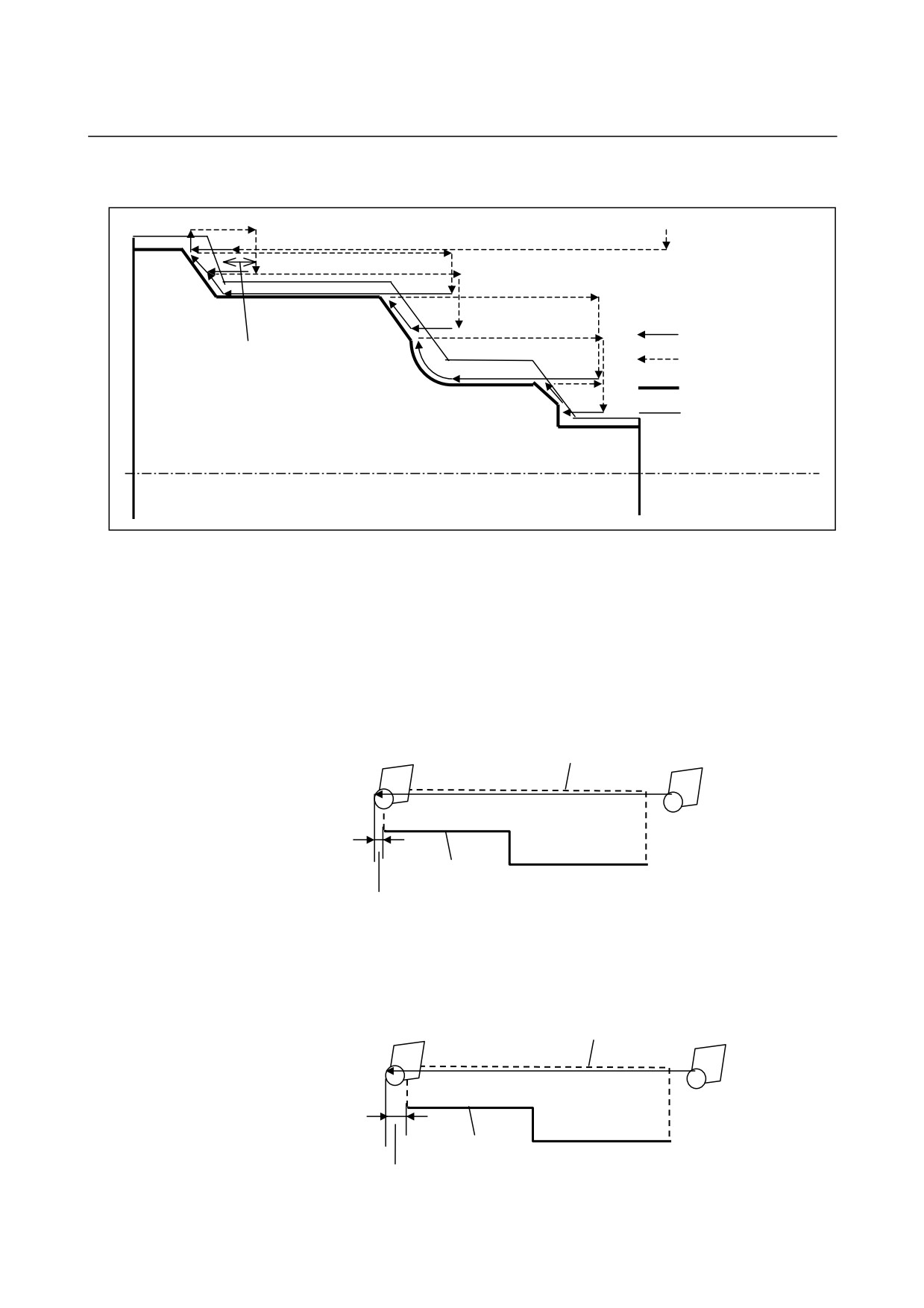
Example of outer-surface machining
Start point
: Tool path for cutting
: Tool path for
Clearance
rapid traverse
: Product figure
: Blank figure
Motion of the tool in the cutting direction on the blank element portion
When the tool advances in the cutting direction, the excessive amount
of travel of the tool is as describe below.
When bit 0 of parameter No. 27120 is set to 0, and the tool advances
in the cutting direction, the excessive amount of travel of the tool is
nose radius R if the attribute of the figure across which the tool moves
is the blank element. In this case, the excessive amount of travel is
the distance from the end point of the part figure.
Blank figure
Product figure
R
When bit 0 of parameter No. 27120 is set to 1, and the tool advances
in the cutting direction, the excessive amount of travel of the tool is
[clearance + 2 × nose radius R] if the attribute of the figure across
which the tool moves is the blank element. In this case, the
excessive amount of travel is the distance from the blank element.
Blank figure
Product figure
Clearance+2R
- 492 -
B-63874EN/05
CYCLE MACHINING TYPES
2.TURNING
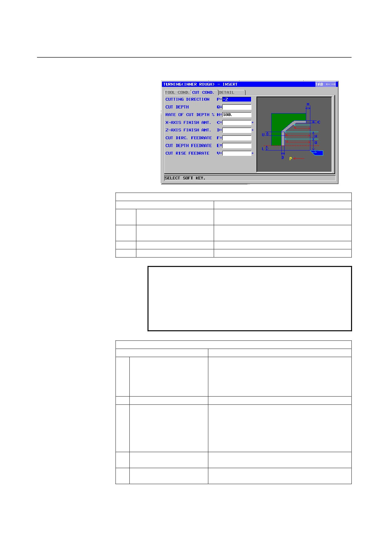
Inner surface roughing: G1121
TOOL COND.
Data item
Meaning
R
NOSE RADIUS
Tool nose radius of a roughing tool (positive
value)
A
CUT EDGE ANGLE
Cutting edge angle of a roughing tool (positive
value)
B
NOSE ANGLE
Tool angle of a roughing tool (positive value)
J
IMAGINARY TOOL NOSE
Imaginary tool nose position of a roughing tool
NOTE
1 Tab ‘TOOL COND.’ is enabled when bit 0 (TLG) of
parameter No. 27102 = 1.
2 The operator ordinarily sets the above data on the
tab of ‘TOOL DATA’ in Tool Offset window.
Therefore, it is not necessary to display the tab
‘TOOL COND.’
CUT COND.
Data item
Meaning
P
CUTTING DIRECTION
[-Z]
: Cuts in the -Z direction.
[+Z]
: Cuts in the +Z direction.
Remark) [+Z] is used for cutting in the reverse
direction or for machining with a
subspindle.
(COPY)
Q
CUT DEPTH
Depth of each cut (radius value, positive value)
H
RATE OF CUT DEPTH
Change rate for the depth of cut. Specify a change
rate in steps of 1%. A second depth of cut and
subsequent ones are sequentially multiplied by a
specified change rate. The default is 100%, meaning
that the depth of cut remains unchanged. (1 to 200,
positive value)
C*
X-AXIS FINISH AMT.
Finishing allowance in the X-axis direction. The
blank is regarded as 0. (radius value, positive value)
D*
Z-AXIS FINISH AMT.
Finishing allowance in the Z-axis direction. The
blank is regarded as 0. (radius value, positive value)
- 493 -

2.TURNING
CYCLE MACHINING TYPES
B-63874EN/05
CUT COND.
Data item
Meaning
F
CUT DIRC.FEEDRATE
Feedrate applicable when the tool cuts in the
workpiece radius direction (positive value)
E
CUT DEPTH FEEDRATE
Feedrate applicable when the tool cuts in the Z-axis
direction (positive value)
V
CUT RISE FEEDRATE
Feedrate applicable when the tool cuts up in the
direction of retraction from the workpiece (positive
value)
DETAIL
Data item
Meaning
K
1ST OVERRIDE
Feedrate override value for the first cut. Specify an
override value in steps of 1%. The default is 100%.
(1 - 200, positive value)
Remark) This data item is used, for example, to cut
the black coating of a cast workpiece.
W
CUT RISE METHOD
[SPEED]: The tool retracts by a distance specified
with ESCAPE AMOUNT in the XZ
direction immediately after cutting.
[CUT]
: The tool retracts by a "retract" distance"
after cutting along the figure.
(COPY)
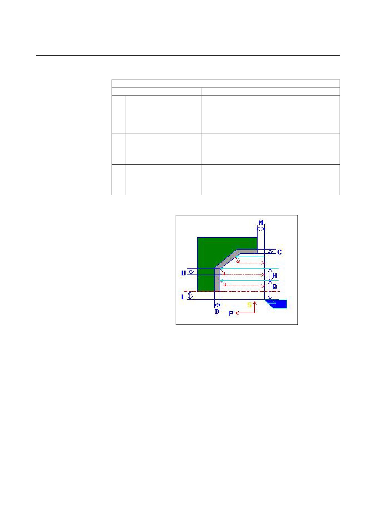
U
ESCAPE AMOUNT
Distance by which the tool retracts from a cutting
surface after each cut (radius value, positive value)
Remark) By referring to the parameter No. 27128
(minimum clamp value), the system sets
the data as an initial value.
L
X-AXIS CLEARANCE
Distance between a blank and machining start point
(approach point) in the X-axis direction (radius
value, positive value)
Remark) By referring to the parameter No. 27129
(minimum clamp value), the system sets
the data as an initial value.
M
Z-AXIS CLEARANCE
Distance between a blank and machining start point
(approach point) in the Z-axis direction (radius value,
positive value)
Remark) By referring to the parameter No. 27130
(minimum clamp value), the system sets
the data as an initial value.
Z
APROCH MOTION
[Z→X]
: From the current position to the
machining start point, the tool moves in
the Z-axis direction and then in the
X-axis direction.
[X→Z]
: From the current position to the
machining start point, the tool moves in
the Z-axis direction and then in the
X-axis direction. (initial value)
[2 AXES]
: From the current position to the
machining start point, the tool moves
simultaneously in the X- and Z-axis
directions.
- 494 -
B-63874EN/05
CYCLE MACHINING TYPES
2.TURNING
DETAIL
Data item
Meaning
S
CUT DEPTH DIRECTION
As to X axis Cut direction,
[-X]
: Cuts in the -X direction.
[+X]
: Cuts in the +X direction.
Remark) This data item is enable when the
parameter No.27100#0 = 1.
(COPY)
X
POCKET CUTTING
[CUT]
: Cuts a pocket. (initial value)
[NOTHIN] : Does not cut a pocket.
Remark) This data item is enable when the
parameter No.27100#1 = 1.
Y
OVERHANG CUTTING
[CUT]
: Cuts an overhang. (initial value)
[NOTHIN] : Does not cut an overhang.
Remark) This data item is enable when the
parameter No.27100#1 = 1.
• Tool path
<1> The tool moves to the position "cut-in start point + clearance (L,
M)" by rapid traverse.
<2> After cutting in in the X-axis direction at the feedrate
(F)
specified for the cutting direction, the tool cuts in to the
entered-figure position where there is still a finishing allowance
in the Z-axis direction at the feedrate (E) specified for the cut-in
direction.
<3> If [SPEED] is selected, the tool immediately retracts by a return
clearance (U) in the X- and Z-axis direction. If [CUT] is selected,
the tool first cuts along the figure and then retracts by a return
clearance (U) in the X- and Z-axis direction.
<4> The tool moves to the cut-in start position in the Z-axis direction
by rapid traverse.
<5> Steps <2> to <4> are repeated until the lowest portion in the
X-axis direction is reached.
<6> If there is another pocket, the tool is positioned on the pocket,
and steps <2> to <4> are repeated.
<7> Once all portions are cut, the tool retracts to the position "cut-in
start position + clearance (M)" in the Z-axis direction at the rapid
traverse rate.
- 495 -
2.TURNING
CYCLE MACHINING TYPES
B-63874EN/05
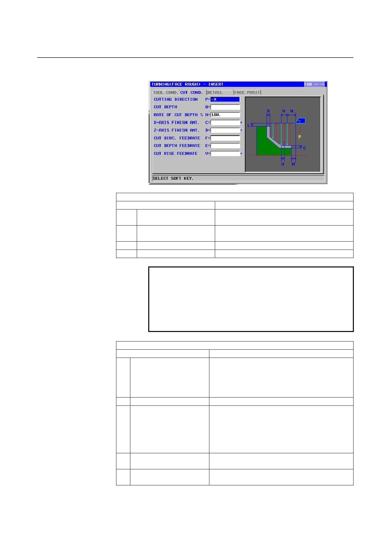
End face roughing: G1122
TOOL COND.
Data item
Meaning
R
NOSE RADIUS
Tool nose radius of a roughing tool (positive
value)
A
CUT EDGE ANGLE
Cutting edge angle of a roughing tool (positive
value)
B
NOSE ANGLE
Tool angle of a roughing tool (positive value)
J
IMAGINARY TOOL NOSE
Imaginary tool nose position of a roughing tool
NOTE
1 Tab ‘TOOL COND.’ is enabled when bit 0 (TLG) of
parameter No. 27102 = 1.
2 The operator ordinarily sets the above data on the
tab of ‘TOOL DATA’ in Tool Offset window.
Therefore, it is not necessary to display the tab
‘TOOL COND.’
CUT COND.
Data item
Meaning
P
CUTTING DIRECTION
[-X]
: Cuts in the -X direction.
[+X]
: Cuts in the +X direction.
Remark) [+X] is used for cutting in the reverse
direction or for machining with a
subspindle.
(COPY)
Q
CUT DEPTH
Depth of each cut (radius value, positive value)
H
RATE OF CUT DEPTH
Change rate for the depth of cut. Specify a change
rate in steps of 1%. A second depth of cut and
subsequent ones are sequentially multiplied by a
specified change rate. The default is 100%, meaning
that the depth of cut remains unchanged. (1 to 200,
positive value)
C*
X-AXIS FINISH AMT.
Finishing allowance in the X-axis direction. The
blank is regarded as 0. (radius value, positive value)
D*
Z-AXIS FINISH AMT.
Finishing allowance in the Z-axis direction. The
blank is regarded as 0. (radius value, positive value)
- 496 -

B-63874EN/05
CYCLE MACHINING TYPES
2.TURNING
CUT COND.
Data item
Meaning
F
CUT DIRC.FEEDRATE
Feedrate applicable when the tool cuts in the
workpiece radius direction (positive value)
E
CUT DEPTH FEEDRATE
Feedrate applicable when the tool cuts in the Z-axis
direction (positive value)
V
CUT RISE FEEDRATE
Feedrate applicable when the tool cuts up in the
direction of retraction from the workpiece (positive
value)
DETAIL
Data item
Meaning
K
1ST OVERRIDE
Feedrate override value for the first cut. Specify an
override value in steps of 1%. The default is 100%.
(1 - 200, positive value)
Remark) This data item is used, for example, to cut
the black coating of a cast workpiece.
W
CUT RISE METHOD
[SPEED]: The tool retracts by a distance specified
with ESCAPE AMOUNT in the XZ
direction immediately after cutting. (initial
value)
[CUT]
: The tool retracts by a "retract" distance"
after cutting along the figure.
(COPY)
U
ESCAPE AMOUNT
Distance by which the tool retracts from a cutting
surface after each cut (radius value, positive value)
Remark) By referring to the parameter No. 27128
(minimum clamp value), the system sets
the data as an initial value.
L
X-AXIS CLEARANCE
Distance between a blank and machining start point
(approach point) in the X-axis direction (radius
value, positive value)
Remark) By referring to the parameter No. 27129
(minimum clamp value), the system sets
the data as an initial value.
M
Z-AXIS CLEARANCE
Distance between a blank and machining start point
(approach point) in the Z-axis direction (radius value,
positive value)
Remark) By referring to the parameter No. 27130
(minimum clamp value), the system sets
the data as an initial value.
Z
APROCH MOTION
[Z→X]
: From the current position to the
machining start point, the tool moves in
the Z-axis direction and then in the
X-axis direction. (initial value)
[X→Z]
: From the current position to the
machining start point, the tool moves in
the Z-axis direction and then in the
X-axis direction.
[2 AXES]
: From the current position to the
machining start point, the tool moves
simultaneously in the X- and Z-axis
directions.
- 497 -
2.TURNING
CYCLE MACHINING TYPES
B-63874EN/05
DETAIL
Data item
Meaning
X
POCKET CUTTING
[CUT]
: Cuts a pocket. (initial value)
[NOTHIN] : Does not cut a pocket.
Remark) This data item is enable when the
parameter No.27100#1 = 1.
Y
OVERHANG CUTTING
[CUT]
: Cuts an overhang. (initial value)
[NOTHIN] : Does not cut an overhang.
Remark) This data item is enable when the
parameter No.27100#1 = 1.
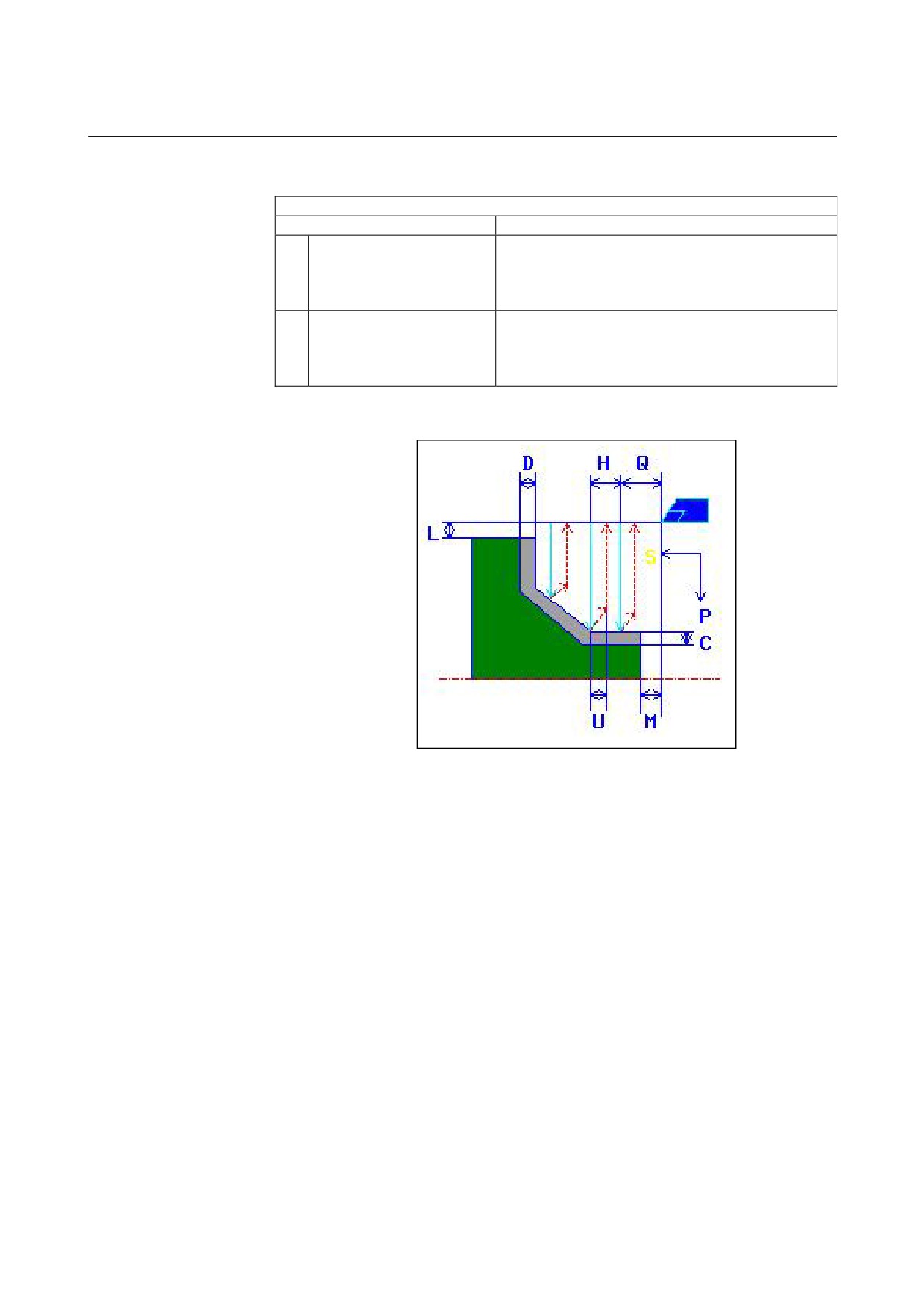
• Tool path
<1> The tool moves to the position "cut-in start point + clearance (L,
M)" by rapid traverse.
<2> After cutting in in the Z-axis direction at the feedrate
(F)
specified for the cutting direction, the tool cuts in to the
entered-figure position where there is still a finishing allowance
in the X-axis direction at the feedrate (E) specified for the cut-in
direction.
<3> If [SPEED] is selected, the tool immediately retracts by a return
clearance (U) in the X- and Z-axis direction. If [CUT] is selected,
the tool first cuts along the figure and then retracts by a return
clearance (U) in the X- and Z-axis direction.
<4> The tool moves to the cut-in start position in the X-axis direction
by rapid traverse.
<5> Steps <2> to <4> are repeated until the lowest portion in the
Z-axis direction is reached.
<6> If there is another pocket, the tool is positioned on the pocket,
and steps <2> to <4> are repeated.
<7> Once all portions are cut, the tool retracts to the position "cut-in
start position + clearance (M)" in the Z-axis direction at the rapid
traverse rate.
- 498 -
B-63874EN/05
CYCLE MACHINING TYPES
2.TURNING
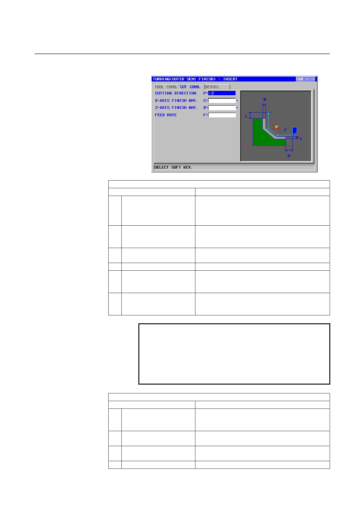
Outer surface semifinishing: G1123
TOOL COND.
Data item
Meaning
I
INPUT TYPE
[INPUT] : Directly inputs the tool nose radius of a
tool used for semifinishing. (initial value)
[REF.]
: Inputs the offset number of a tool used for
semifinishing to read the offset value.
R
NOSE RADIUS
Tool nose radius of a roughing tool (positive value)
Remark) This data item is indicated only when
[INPUT] is selected for INPUT TYPE.
A
CUT EDGE ANGLE
Cutting edge angle of a roughing tool (positive
value)
B
NOSE ANGLE
Tool angle of a roughing tool (positive value)
J
IMAGINARY TOOL NOSE
Imaginary tool nose position of a roughing tool
Remark) This data item is indicated only when
[INPUT] is selected for INPUT TYPE.
T
OFFSET NO.
Offset number of a roughing tool (positive value)
Remark) This data item is indicated only when
[REF.] is selected for INPUT TYPE.
NOTE
1 Tab ‘TOOL COND.’ is enabled when bit 0 (TLG) of
parameter No. 27102 = 1.
2 The operator ordinarily sets the above data on the
tab of ‘TOOL DATA’ in Tool Offset window.
Therefore, it is not necessary to display the tab
‘TOOL COND.’
CUT COND.
Data item
Meaning
P
CUTTING DIRECTION
[-Z]
: Cuts in the -Z direction.
[+Z]
: Cuts in the +Z direction.
(COPY)
C*
X-AXIS FINISH AMT.
Finishing allowance in the X-axis direction. The
blank is regarded as 0. (radius value, positive value)
D*
Z-AXIS FINISH AMT.
Finishing allowance in the Z-axis direction. The
blank is regarded as 0. (radius value, positive value)
F
FEED RATE
Cutting feedrate for semifinishing (positive value)
- 499 -

2.TURNING
CYCLE MACHINING TYPES
B-63874EN/05
DETAIL
Data item
Meaning
L
X-AXIS CLEARANCE
Distance between a blank and machining start point
(approach point) in the X-axis direction (radius
value, positive value)
Remark) By referring to the parameter No.
27129(minimum clamp value), the system
sets the data as an initial value.
M
Z-AXIS CLEARANCE
Distance between a blank and machining start point
(approach point) in the Z-axis direction (radius value,
positive value)
Remark) By referring to the parameter No. 27130
(minimum clamp value), the system sets
the data as an initial value.
Z
APROCH MOTION
[Z→X]
: From the current position to the
machining start point, the tool moves in
the Z-axis direction and then in the
X-axis direction. (initial value)
[X→Z]
: From the current position to the
machining start point, the tool moves in
the Z-axis direction and then in the
X-axis direction.
[2 AXES]
: From the current position to the
machining start point, the tool moves
simultaneously in the X- and Z-axis
directions.
S
CUT DEPTH DIRECTION
As to X axis Cut direction,
[-X]
: Cuts in the -X direction.
[+X]
: Cuts in the +X direction.
Remark) This data item is enable when the
parameter No.27100#0 = 1.
(COPY)
X
POCKET CUTTING
[CUT]
: Cuts a pocket. (initial value)
[NOTHIN] : Does not cut a pocket.
Remark) This data item is enable when the
parameter No.27100#1 = 1.
Y
OVERHANG CUTTING
[CUT]
: Cuts an overhang. (initial value)
[NOTHIN] : Does not cut an overhang.
Remark) This data item is enable when the
parameter No.27100#1 = 1.
- 500 -
B-63874EN/05
CYCLE MACHINING TYPES
2.TURNING
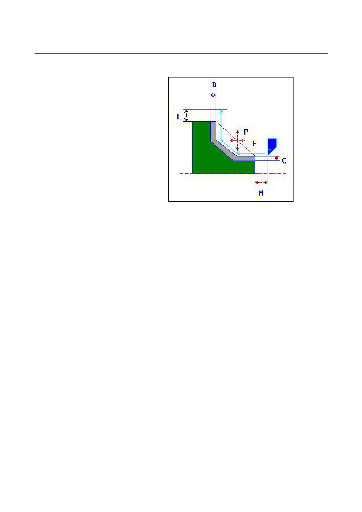
• Tool path
<1> The tool moves to the position "cut-in start point + clearance (L,
M)" by rapid traverse.
<2> The tool cuts along the entered figure on which the finishing
allowance is left uncut at the semifinishing feedrate until the final
figure is obtained.
<3> Once all portions are cut, the tool retracts to the position "cut-in
start position + clearance (L)" in the X-axis direction at the rapid
traverse rate.
- 501 -
2.TURNING
CYCLE MACHINING TYPES
B-63874EN/05
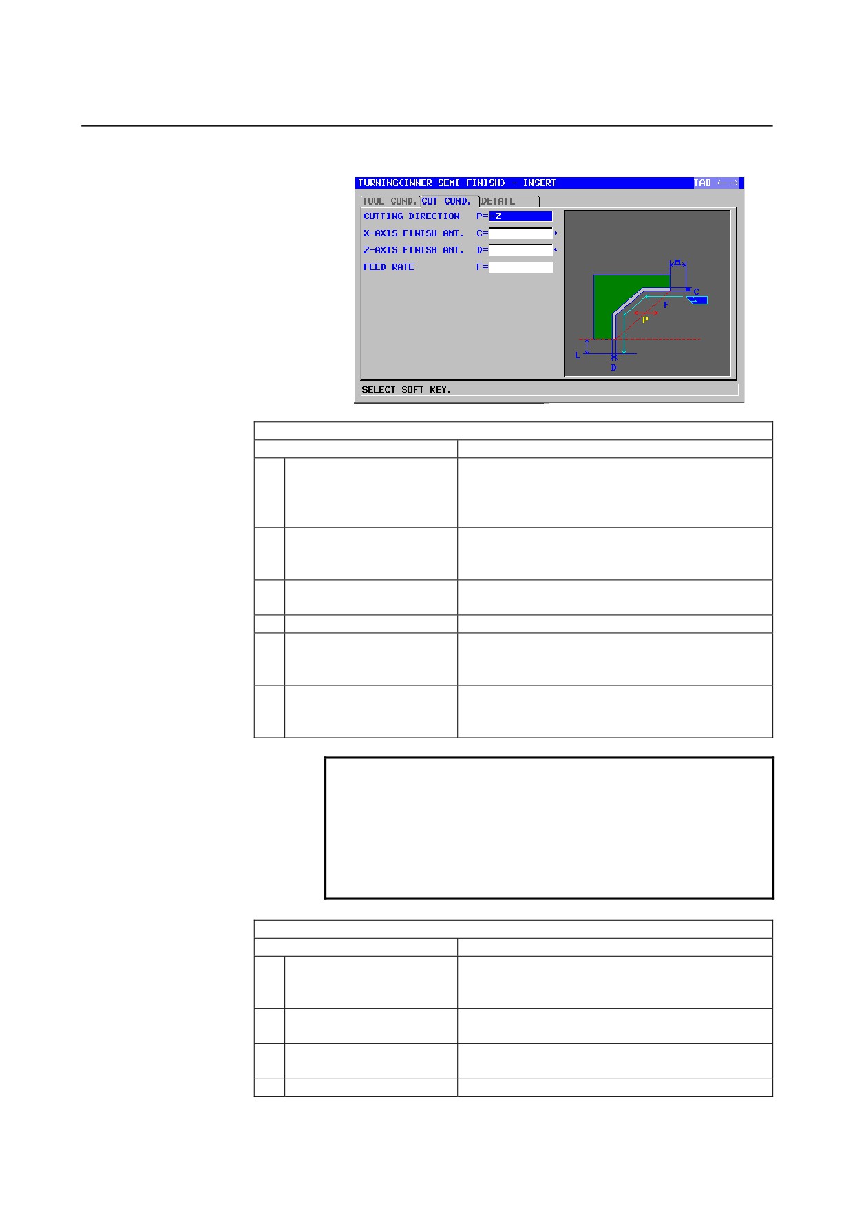
Inner surface semifinishing: G1124
TOOL COND.
Data item
Meaning
I
INPUT TYPE
[INPUT] : Directly inputs the tool nose radius of a
tool used for semifinishing. (initial value)
[REF.]
: Inputs the offset number of a tool used for
semifinishing to read the offset value.
R
NOSE RADIUS
Tool nose radius of a roughing tool (positive value)
Remark) This data item is indicated only when
[INPUT] is selected for INPUT TYPE.
A
CUT EDGE ANGLE
Cutting edge angle of a roughing tool (positive
value)
B
NOSE ANGLE
Tool angle of a roughing tool (positive value)
J
IMAGINARY TOOL NOSE
Imaginary tool nose position of a roughing tool
Remark) This data item is indicated only when
[INPUT] is selected for INPUT TYPE.
T
OFFSET NO.
Offset number of a roughing tool (positive value)
Remark) This data item is indicated only when
[REF.] is selected for INPUT TYPE.
NOTE
1 Tab ‘TOOL COND.’ is enabled when bit 0 (TLG) of
parameter No. 27102 = 1.
2 The operator ordinarily sets the above data on the
tab of ‘TOOL DATA’ in Tool Offset window.
Therefore, it is not necessary to display the tab
‘TOOL COND.’
CUT COND.
Data item
Meaning
P
CUTTING DIRECTION
[-Z]
: Cuts in the -Z direction.
[+Z]
: Cuts in the +Z direction.
(COPY)
C*
X-AXIS FINISH AMT.
Finishing allowance in the X-axis direction. The
blank is regarded as 0. (radius value, positive value)
D*
Z-AXIS FINISH AMT.
Finishing allowance in the Z-axis direction. The
blank is regarded as 0. (radius value, positive value)
F
FEED RATE
Cutting feedrate for semifinishing (positive value)
- 502 -

B-63874EN/05
CYCLE MACHINING TYPES
2.TURNING
DETAIL
Data item
Meaning
L
X-AXIS CLEARANCE
Distance between a blank and machining start point
(approach point) in the X-axis direction (radius
value, positive value)
Remark) By referring to the parameter No. 27129
(minimum clamp value), the system sets
the data as an initial value.
M
Z-AXIS CLEARANCE
Distance between a blank and machining start point
(approach point) in the Z-axis direction (radius value,
positive value)
Remark) By referring to the parameter No. 27130
(minimum clamp value), the system sets
the data as an initial value.
Z
APROCH MOTION
[Z→X]
: From the current position to the
machining start point, the tool moves in
the Z-axis direction and then in the
X-axis direction.
[X→Z]
: From the current position to the
machining start point, the tool moves in
the Z-axis direction and then in the
X-axis direction. (initial value)
[2 AXES]
: From the current position to the
machining start point, the tool moves
simultaneously in the X- and Z-axis
directions.
S
CUT DEPTH DIRECTION
As to X axis Cut direction,
[-X]
: Cuts in the -X direction.
[+X]
: Cuts in the +X direction.
Remark) This data item is enable when the
parameter No.27100#0 = 1.
(COPY)
X
POCKET CUTTING
[CUT]
: Cuts a pocket. (initial value)
[NOTHIN] : Does not cut a pocket.
Remark) This data item is enable when the
parameter No.27100#1 = 1.
Y
OVERHANG CUTTING
[CUT]
: Cuts an overhang. (initial value)
[NOTHIN] : Does not cut an overhang.
Remark) This data item is enable when the
parameter No.27100#1 = 1.
- 503 -
2.TURNING
CYCLE MACHINING TYPES
B-63874EN/05
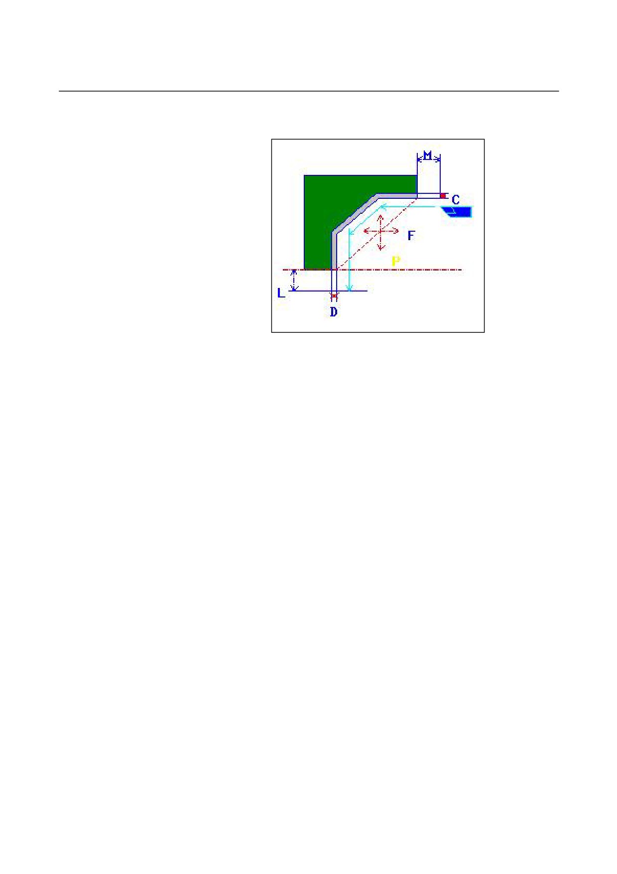
• Tool path
<1> The tool moves to the position "cut-in start point + clearance (L,
M)" by rapid traverse.
<2> The tool cuts along the entered figure on which the finishing
allowance is left uncut at the semifinishing feedrate until the final
figure is obtained.
<3> Once all portions are cut, the tool retracts to the position "cut-in
start position + clearance (M)" in the Z-axis direction at the rapid
traverse rate.
- 504 -
B-63874EN/05
CYCLE MACHINING TYPES
2.TURNING
End face semifinishing: G1125
TOOL COND.
Data item
Meaning
I
INPUT TYPE
[INPUT] : Directly inputs the tool nose radius of a
tool used for semifinishing. (initial value)
[REF.]
: Inputs the offset number of a tool used for
semifinishing to read the offset value.
R
NOSE RADIUS
Tool nose radius of a roughing tool (positive value)
Remark) This data item is indicated only when
[INPUT] is selected for INPUT TYPE.
A
CUT EDGE ANGLE
Cutting edge angle of a roughing tool (positive
value)
B
NOSE ANGLE
Tool angle of a roughing tool (positive value)
J
IMAGINARY TOOL NOSE
Imaginary tool nose position of a roughing tool
Remark) This data item is indicated only when
[INPUT] is selected for INPUT TYPE.
T
OFFSET NO.
Offset number of a roughing tool (positive value)
Remark) This data item is indicated only when
[REF.] is selected for INPUT TYPE.
NOTE
1 Tab ‘TOOL COND.’ is enabled when bit 0 (TLG) of
parameter No. 27102 = 1.
2 The operator ordinarily sets the above data on the
tab of ‘TOOL DATA’ in Tool Offset window.
Therefore, it is not necessary to display the tab
‘TOOL COND.’
- 505 -

2.TURNING
CYCLE MACHINING TYPES
B-63874EN/05
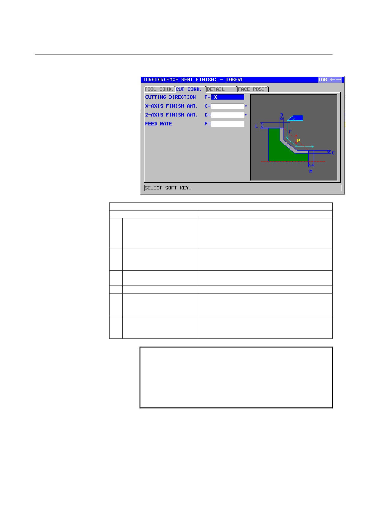
CUT COND.
Data item
Meaning
P
CUTTING DIRECTION
[-X]
: Cuts in the -X direction.
[+X]
: Cuts in the +X direction.
(COPY)
C*
X-AXIS FINISH AMT.
Finishing allowance in the X-axis direction. The
blank is regarded as 0. (radius value, positive value)
D*
Z-AXIS FINISH AMT.
Finishing allowance in the Z-axis direction. The
blank is regarded as 0. (radius value, positive value)
F
FEED RATE
Cutting feedrate for semifinishing (positive value)
DETAIL
Data item
Meaning
L
X-AXIS CLEARANCE
Distance between a blank and machining start point
(approach point) in the X-axis direction (radius
value, positive value)
Remark) By referring to the parameter No. 27129
(minimum clamp value), the system sets
the data as an initial value.
M
Z-AXIS CLEARANCE
Distance between a blank and machining start point
(approach point) in the Z-axis direction (radius value,
positive value)
Remark) By referring to the parameter No. 27130
(minimum clamp value), the system sets
the data as an initial value.
Z
APROCH MOTION
[Z→X]
: From the current position to the
machining start point, the tool moves in
the Z-axis direction and then in the
X-axis direction. (initial value)
[X→Z]
: From the current position to the
machining start point, the tool moves in
the Z-axis direction and then in the
X-axis direction.
[2 AXES]
: From the current position to the
machining start point, the tool moves
simultaneously in the X- and Z-axis
directions.
X
POCKET CUTTING
[CUT]
: Cuts a pocket. (initial value)
[NOTHIN] : Does not cut a pocket.
Remark) This data item is enable when the
parameter No.27100#1 = 1.
Y
OVERHANG CUTTING
[CUT]
: Cuts an overhang. (initial value)
[NOTHIN] : Does not cut an overhang.
Remark) This data item is enable when the
parameter No.27100#1 = 1.
- 506 -
B-63874EN/05
CYCLE MACHINING TYPES
2.TURNING
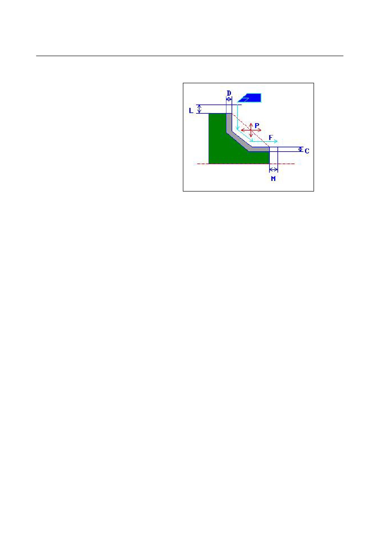
• Tool path
<1> The tool moves to the position "cut-in start point + clearance (L,
M)" by rapid traverse.
<2> The tool cuts along the entered figure on which the finishing
allowance is left uncut at the semifinishing feedrate until the final
figure is obtained.
<3> Once all portions are cut, the tool retracts to the position "cut-in
start position + clearance (M)" in the Z-axis direction at the rapid
traverse rate.
- 507 -
2.TURNING
CYCLE MACHINING TYPES
B-63874EN/05
Outer surface finishing: G1126
TOOL COND.
Data item
Meaning
I
INPUT TYPE
[INPUT] : Directly inputs the tool nose radius of a
tool used for semifinishing. (initial value)
[REF.]
: Inputs the offset number of a tool used for
semifinishing to read the offset value.
R
NOSE RADIUS
Tool nose radius of a roughing tool (positive value)
Remark) This data item is indicated only when
[INPUT] is selected for INPUT TYPE.
A
CUT EDGE ANGLE
Cutting edge angle of a roughing tool (positive
value)
B
NOSE ANGLE
Tool angle of a roughing tool (positive value)
J
IMAGINARY TOOL NOSE
Imaginary tool nose position of a roughing tool
Remark) This data item is indicated only when
[INPUT] is selected for INPUT TYPE.
T
OFFSET NO.
Offset number of a roughing tool (positive value)
Remark) This data item is indicated only when
[REF.] is selected for INPUT TYPE.
NOTE
1 Tab ‘TOOL COND.’ is enabled when bit 0 (TLG) of
parameter No. 27102 = 1.
2 The operator ordinarily sets the above data on the
tab of ‘TOOL DATA’ in Tool Offset window.
Therefore, it is not necessary to display the tab
‘TOOL COND.’
- 508 -

B-63874EN/05
CYCLE MACHINING TYPES
2.TURNING
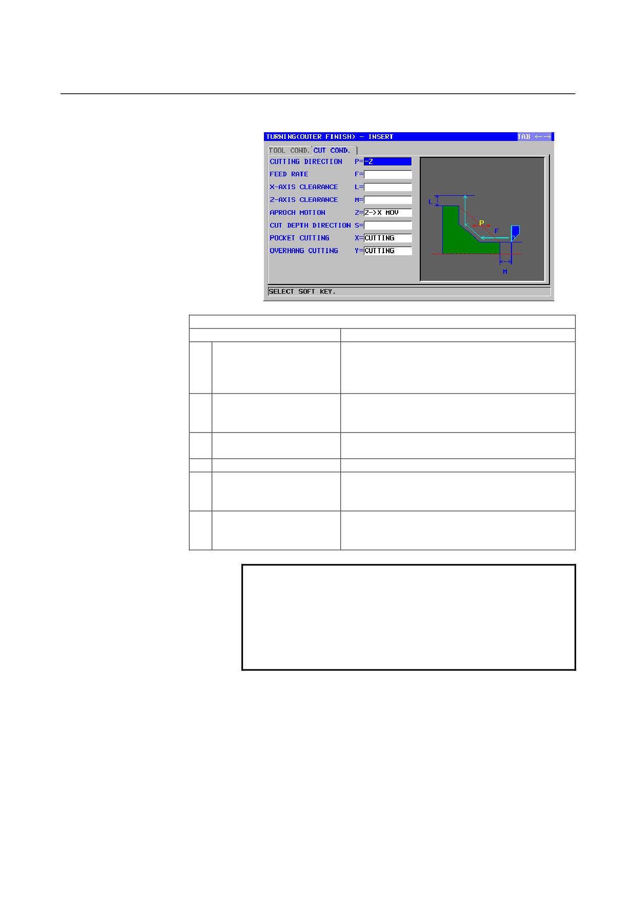
CUT COND.
Data item
Meaning
P
CUTTING DIRECTION
[-Z]
: Cuts in the -Z direction.
[+Z]
: Cuts in the +Z direction.
(COPY)
F
FEED RATE
Cutting feedrate for finishing (positive value)
L
X-AXIS CLEARANCE
Distance between a blank and machining start point
(approach point) in the X-axis direction (radius
value, positive value)
Remark) By referring to the parameter No. 27129
(minimum clamp value), the system sets the
data as an initial value.
M
Z-AXIS CLEARANCE
Distance between a blank and machining start point
(approach point) in the Z-axis direction (radius value,
positive value)
Remark) By referring to the parameter No. 27130
(minimum clamp value), the system sets
the data as an initial value.
Z
APROCH MOTION
[Z→X]
: From the current position to the
machining start point, the tool moves in
the Z-axis direction and then in the
X-axis direction. (initial value)
[X→Z]
: From the current position to the
machining start point, the tool moves in
the Z-axis direction and then in the
X-axis direction.
[2 AXES]
: From the current position to the
machining start point, the tool moves
simultaneously in the X- and Z-axis
directions.
S
CUT DEPTH DIRECTION
As to X axis Cut direction,
[-X]
: Cuts in the -X direction.
[+X]
: Cuts in the +X direction.
Remark) This data item is enable when the
parameter No.27100#0 = 1.
(COPY)
X
POCKET CUTTING
[CUT]
: Cuts a pocket. (initial value)
[NOTHIN] : Does not cut a pocket.
Remark) This data item is enable when the
parameter No.27100#1 = 1.
Y
OVERHANG CUTTING
[CUT]
: Cuts an overhang. (initial value)
[NOTHIN] : Does not cut an overhang.
Remark) This data item is enable when the
parameter No.27100#1 = 1.
- 509 -
2.TURNING
CYCLE MACHINING TYPES
B-63874EN/05
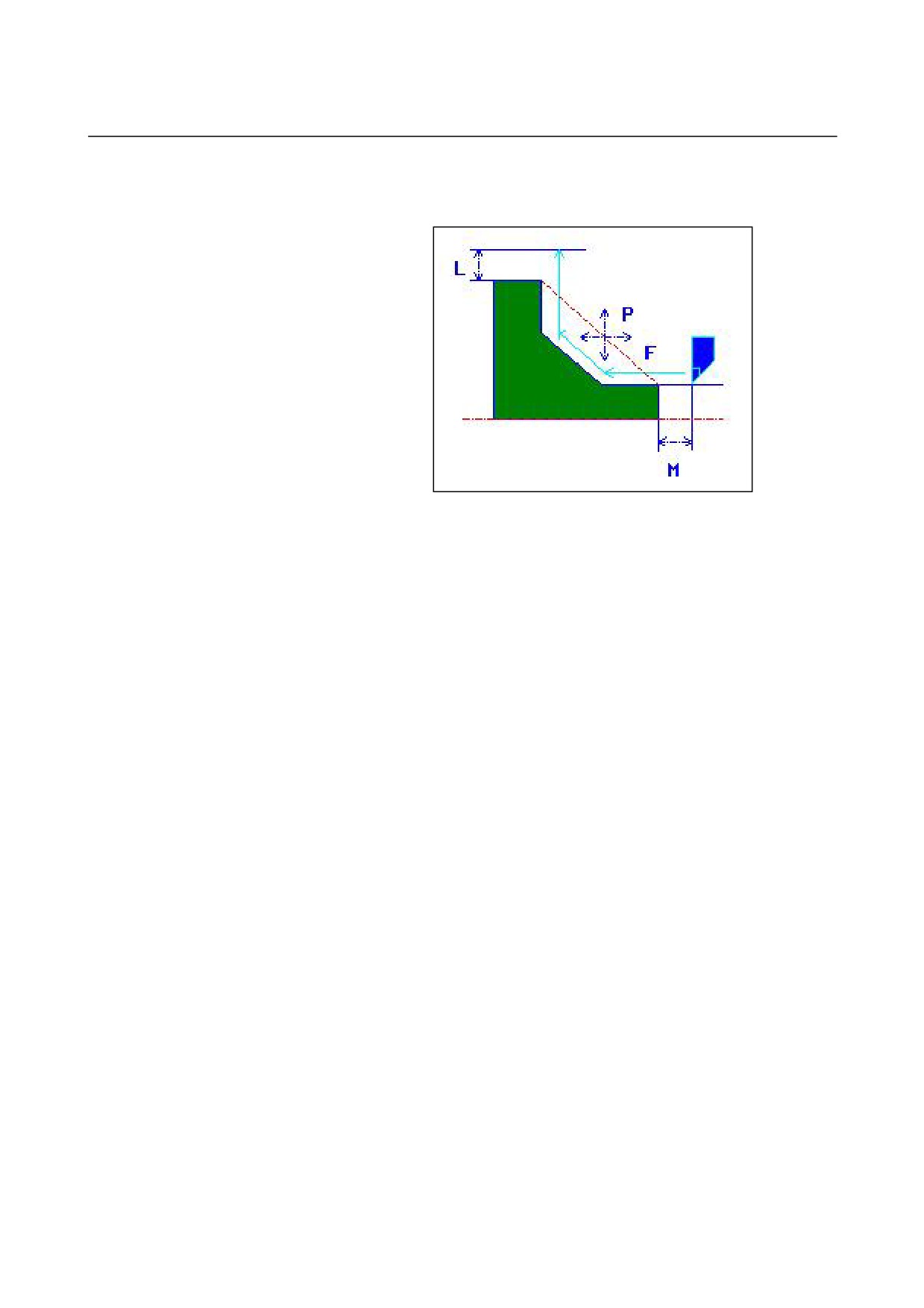
• Tool path
<1> The tool moves to the position "cut-in start point + clearance (L,
M)" by rapid traverse.
<2> The tool cuts along the entered figure at the finishing feedrate
until the final figure is obtained.
<3> Once all portions are cut, the tool retracts to the position "cut-in
start position + clearance (L)" in the X-axis direction at the rapid
traverse rate.
- 510 -
B-63874EN/05
CYCLE MACHINING TYPES
2.TURNING
Inner surface finishing: G1127
TOOL COND.
Data item
Meaning
I
INPUT TYPE
[INPUT] : Directly inputs the tool nose radius of a
tool used for semifinishing. (initial value)
[REF.]
: Inputs the offset number of a tool used for
semifinishing to read the offset value.
R
NOSE RADIUS
Tool nose radius of a roughing tool (positive value)
Remark) This data item is indicated only when
[INPUT] is selected for INPUT TYPE.
A
CUT EDGE ANGLE
Cutting edge angle of a roughing tool (positive
value)
B
NOSE ANGLE
Tool angle of a roughing tool (positive value)
J
IMAGINARY TOOL NOSE
Imaginary tool nose position of a roughing tool
Remark) This data item is indicated only when
[INPUT] is selected for INPUT TYPE.
T
OFFSET NO.
Offset number of a roughing tool (positive value)
Remark) This data item is indicated only when
[REF.] is selected for INPUT TYPE.
NOTE
1 Tab ‘TOOL COND.’ is enabled when bit 0 (TLG) of
parameter No. 27102 = 1.
2 The operator ordinarily sets the above data on the
tab of ‘TOOL DATA’ in Tool Offset window.
Therefore, it is not necessary to display the tab
‘TOOL COND.’
- 511 -

2.TURNING
CYCLE MACHINING TYPES
B-63874EN/05
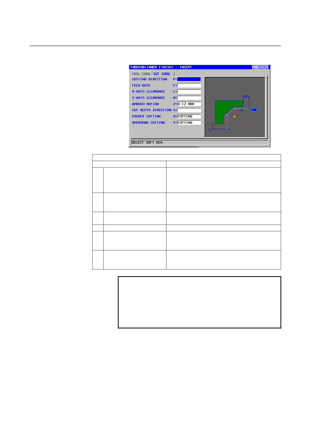
CUT COND.
Data item
Meaning
P
CUTTING DIRECTION
[-Z]
: Cuts in the -Z direction.
[+Z]
: Cuts in the +Z direction.
(COPY)
F
FEED RATE
Cutting feedrate for finishing (positive value)
L
X-AXIS CLEARANCE
Distance between a blank and machining start point
(approach point) in the X-axis direction (radius
value, positive value)
Remark) By referring to the parameter No. 27129
(minimum clamp value), the system sets the
data as an initial value.
M
Z-AXIS CLEARANCE
Distance between a blank and machining start point
(approach point) in the Z-axis direction (radius value,
positive value)
Remark) By referring to the parameter No. 27130
(minimum clamp value), the system sets
the data as an initial value.
Z
APROCH MOTION
[Z→X]
: From the current position to the
machining start point, the tool moves in
the Z-axis direction and then in the
X-axis direction.
[X→Z]
: From the current position to the
machining start point, the tool moves in
the Z-axis direction and then in the
X-axis direction. (initial value)
[2 AXES]
: From the current position to the
machining start point, the tool moves
simultaneously in the X- and Z-axis
directions.
S
CUT DEPTH DIRECTION
As to X axis Cut direction,
[-X]
: Cuts in the -X direction.
[+X]
: Cuts in the +X direction.
Remark) This data item is enable when the
parameter No.27100#0 = 1.
(COPY)
X
POCKET CUTTING
[CUT]
: Cuts a pocket. (initial value)
[NOTHIN] : Does not cut a pocket.
Remark) This data item is enable when the
parameter No.27100#1 = 1.
Y
OVERHANG CUTTING
[CUT]
: Cuts an overhang. (initial value)
[NOTHIN] : Does not cut an overhang.
Remark) This data item is enable when the
parameter No.27100#1 = 1.
- 512 -
B-63874EN/05
CYCLE MACHINING TYPES
2.TURNING
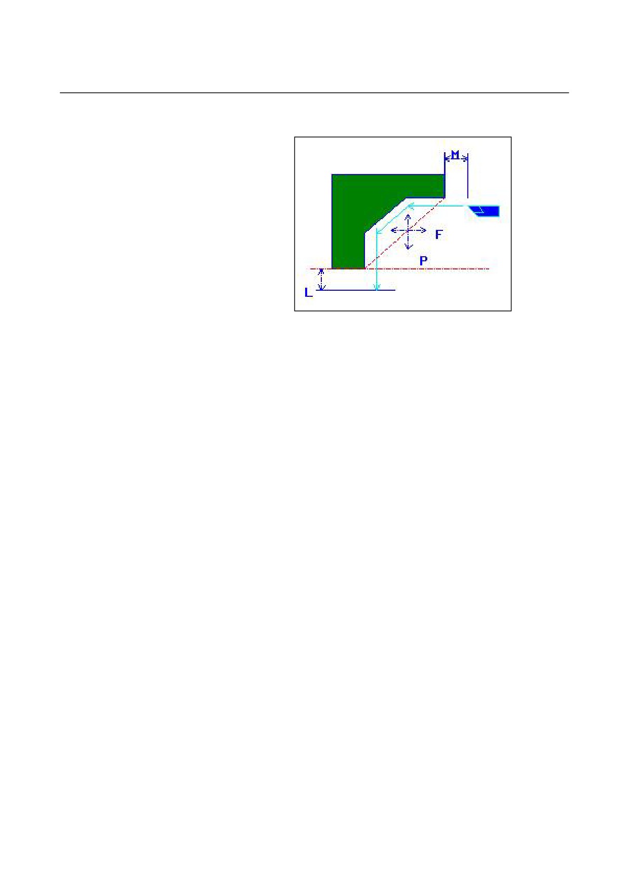
• Tool path
<1> The tool moves to the position "cut-in start point + clearance (L,
M)" by rapid traverse.
<2> The tool cuts along the entered figure at the finishing feedrate
until the final figure is obtained.
<3> Once all portions are cut, the tool retracts to the position "cut-in
start position + clearance (M)" in the Z-axis direction at the rapid
traverse rate.
- 513 -
2.TURNING
CYCLE MACHINING TYPES
B-63874EN/05
End face finishing: G1128
TOOL COND.
Data item
Meaning
I
INPUT TYPE
[INPUT] : Directly inputs the tool nose radius of a
tool used for semifinishing.
[REF.]
: Inputs the offset number of a tool used for
semifinishing to read the offset value.
R
NOSE RADIUS
Tool nose radius of a roughing tool (positive value)
Remark) This data item is indicated only when
[INPUT] is selected for INPUT TYPE.
A
CUT EDGE ANGLE
Cutting edge angle of a roughing tool (positive
value)
B
NOSE ANGLE
Tool angle of a roughing tool (positive value)
J
IMAGINARY TOOL NOSE
Imaginary tool nose position of a roughing tool
Remark) This data item is indicated only when
[INPUT] is selected for INPUT TYPE.
T
OFFSET NO.
Offset number of a roughing tool (positive value)
Remark) This data item is indicated only when
[REF.] is selected for INPUT TYPE.
NOTE
1 Tab ‘TOOL COND.’ is enabled when bit 0 (TLG) of
parameter No. 27102 = 1.
2 The operator ordinarily sets the above data on the
tab of ‘TOOL DATA’ in Tool Offset window.
Therefore, it is not necessary to display the tab
‘TOOL COND.’
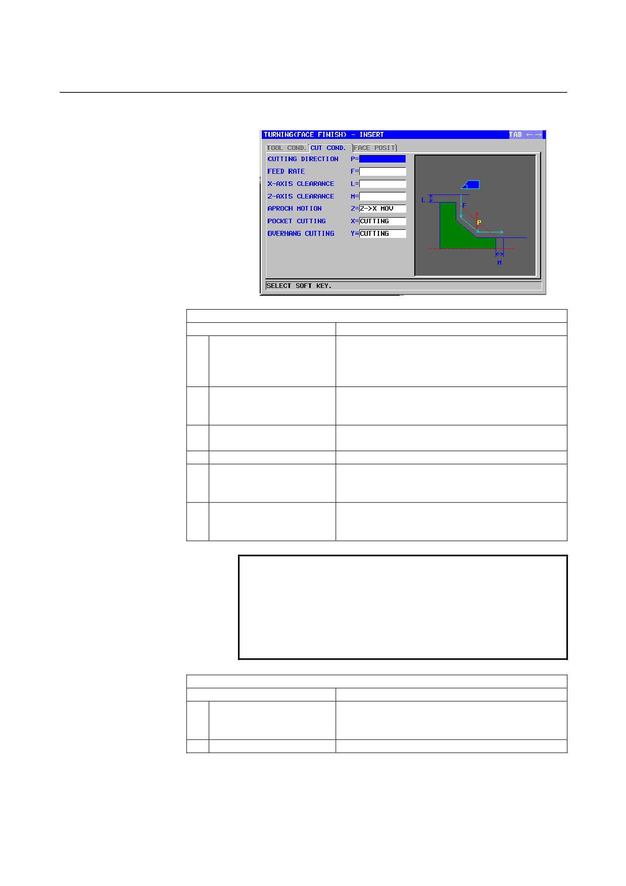
CUT COND.
Data item
Meaning
P
CUTTING DIRECTION
[-X]
: Cuts in the -X direction.
[+X]
: Cuts in the +X direction.
(COPY)
F
FEED RATE
Cutting feedrate for finishing (positive value)
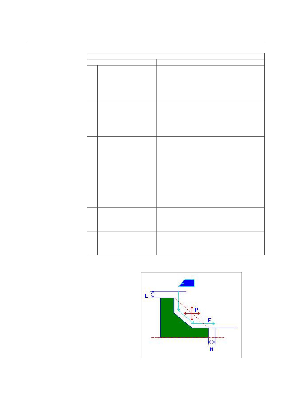
- 514 -
B-63874EN/05
CYCLE MACHINING TYPES
2.TURNING
CUT COND.
Data item
Meaning
L
X-AXIS CLEARANCE
Distance between a blank and machining start point
(approach point) in the X-axis direction (radius
value, positive value)
Remark) By referring to the parameter No. 27129
(minimum clamp value), the system sets the
data as an initial value.
M
Z-AXIS CLEARANCE
Distance between a blank and machining start point
(approach point) in the Z-axis direction (radius value,
positive value)
Remark) By referring to the parameter No. 27130
(minimum clamp value), the system sets
the data as an initial value.
Z
APROCH MOTION
[Z→X]
: From the current position to the
machining start point, the tool moves in
the Z-axis direction and then in the
X-axis direction. (initial value)
[X→Z]
: From the current position to the
machining start point, the tool moves in
the Z-axis direction and then in the
X-axis direction.
[2 AXES]
: From the current position to the
machining start point, the tool moves
simultaneously in the X- and Z-axis
directions.
X
POCKET CUTTING
[CUT]
: Cuts a pocket. (initial value)
[NOTHIN] : Does not cut a pocket.
Remark) This data item is enable when the
parameter No.27100#1 = 1.
Y
OVERHANG CUTTING
[CUT]
: Cuts an overhang. (initial value)
[NOTHIN] : Does not cut an overhang.
Remark) This data item is enable when the
parameter No.27100#1 = 1.
•
Tool path
<1> The tool moves to the position "cut-in start point + clearance (L,
M)" by rapid traverse.
- 515 -
2.TURNING
CYCLE MACHINING TYPES
B-63874EN/05
<2> The tool cuts along the entered figure at the finishing feedrate
until the final figure is obtained.
<3> Once all portions are cut, the tool retracts to the position "cut-in
start position + clearance (M)" in the Z-axis direction at the rapid
traverse rate.
2.2.2
Arbitrary Figure Blocks for Turning
When an arbitrary figure is input, a function such as the automatic
intersection calculation function can be used. For details, see Section 5.5,
"ARBITRARY FIGURES FOR TURNING (ZX PLANE)," in Part II.
- 516 -
B-63874EN/05
CYCLE MACHINING TYPES
2.TURNING
2.3
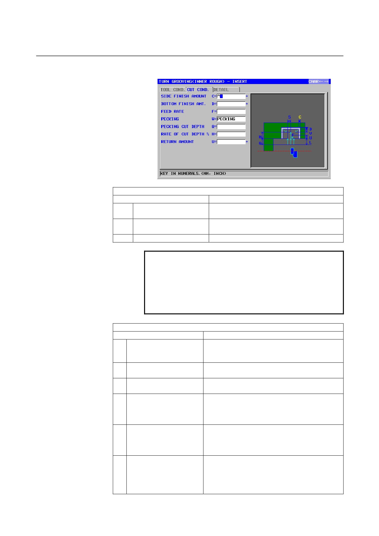
TURNING GROOVING
2.3.1
Machining Type Blocks for Turning Grooving
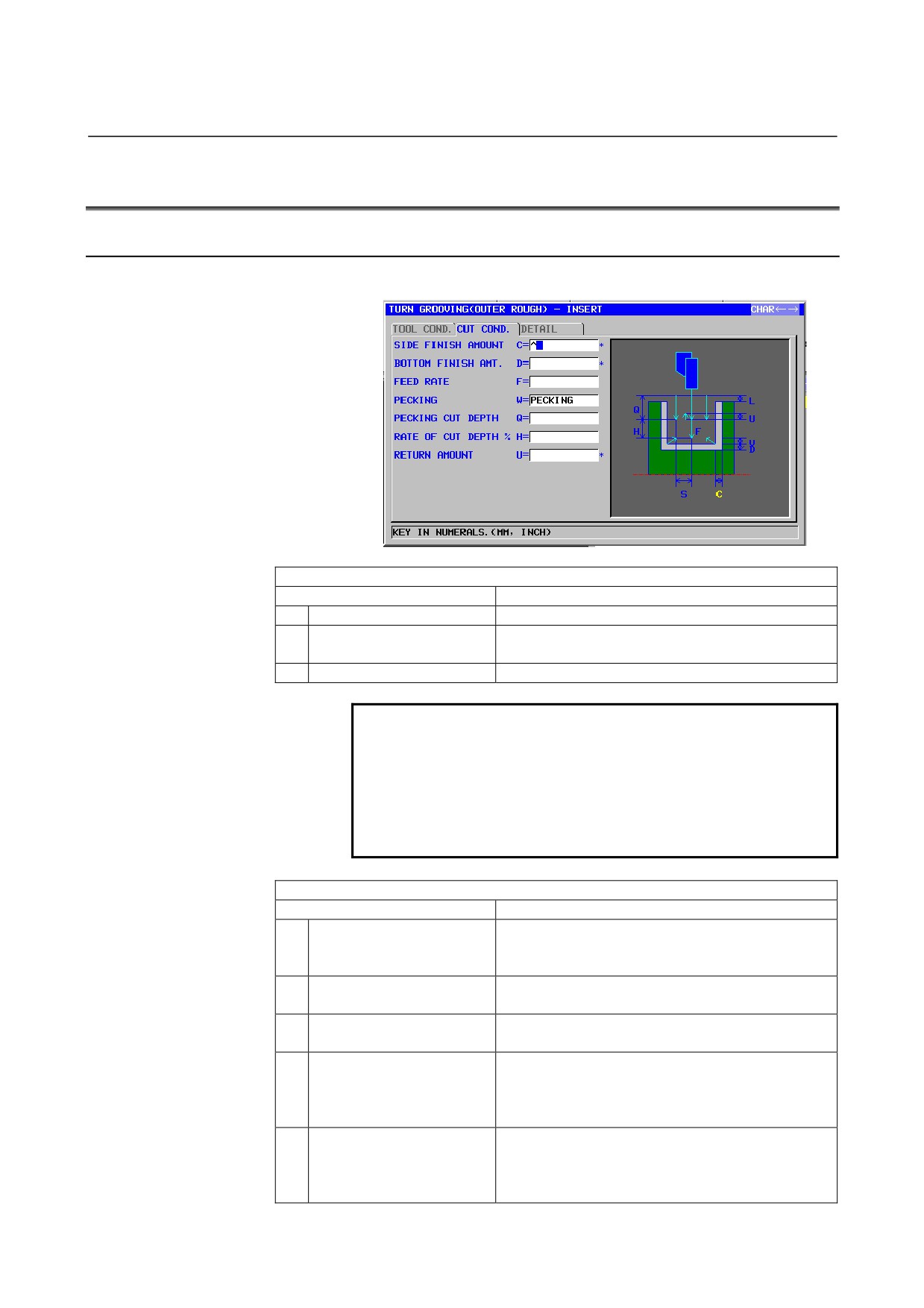
Outer surface roughing: G1130
TOOL COND.
Data item
Meaning
R
NOSE RADIUS
Tool nose radius of a grooving tool. (positive value)
B
TOOL WIDTH
Tool width of a grooving tool (radius value, positive
value)
J
IMAGINARY TOOL NOSE
Imaginary tool nose position of a grooving tool.
NOTE
1 Tab ‘TOOL COND.’ is enabled when bit 0 (TLG) of
parameter No. 27102 = 1.
2 The operator ordinarily sets the above data on the
tab of ‘TOOL DATA’ in Tool Offset window.
Therefore, it is not necessary to display the tab
‘TOOL COND.’
CUT COND.
Data item
Meaning
C*
SIDE FINISH AMOUNT
Finishing allowance for the side faces of a groove.
The blank is regarded as 0. (radius value, positive
value)
D*
BOTTOM FINISH AMT.
Finishing allowance for the bottom of a groove. The
blank is regarded as 0. (radius value, positive value)
F
FEED RATE
Feedrate for cutting in the tool axis direction
(positive value)
W
PECKING
[NOTHIN] : Does not perform pecking in cutting for
grooving (initial value).
[PECKIN] : Performs pecking in cutting for
grooving.
Q
PECKING CUT DEPTH
Depth of cut in the tool axis direction per pecking
operation (radius value, positive value)
Remark) This data item is indicated only when
[PECKIN] is selected for PECKING.
- 517 -
2.TURNING
CYCLE MACHINING TYPES
B-63874EN/05
CUT COND.
Data item
Meaning
H
RATE OF CUT DEPTH
Change rate for the depth of cut. Specify a change
rate in steps of 1%. A second depth of cut and
subsequent ones are sequentially multiplied by a
specified change rate. (1 to 200, positive value)
(COPY)
U*
ESCAPE AMOUNT
Distance by which the tool retracts from a cutting
surface after each cut by pecking. (radius value,
positive value)
(COPY)
DETAIL
Data item
Meaning
L
CLEARANCE
Distance between the top surface of a groove and a
machining start point (approach point) in the Z-axis
direction (radius value, positive value)
Remark) By referring to the parameter No. 27176
(minimum clamp value), the system sets
the data as an initial value.
P
DWELL
Dwell time applicable when the tool reaches the
bottom of a groove.
(in seconds, positive value)
(COPY)
Z
APROCH MOTION
[Z→X]
: From the current position to the
machining start point, the tool moves in
the Z-axis direction and then in the
X-axis direction. (initial value)
[X→Z]
: From the current position to the
machining start point, the tool moves in
the Z-axis direction and then in the
X-axis direction.
[2 AXES]
: From the current position to the
machining start point, the tool moves
simultaneously in the X- and Z-axis
directions.
S
CUT DEPTH FOR WIDTH
Depth of each cut in the grooving tool width direction
(radius value, positive value)
(COPY)
V*
ESCAPE AMOUNT
Distance by which the tool retracts from a cutting
surface after each cut. The blank is regarded as 0.
(radius value, positive value)
Remark) By referring to the parameter No. 27177
(minimum clamp value), the system sets
the data as an initial value.
A
CUT DEPTH DIRECTION
As to X axis Cut direction,
[-X]
: Cuts in the -X direction.
[+X]
: Cuts in the +X direction.
Remark) This data item is enable when the
parameter No.27100#0 = 1.
(COPY)
- 518 -
B-63874EN/05
CYCLE MACHINING TYPES
2.TURNING
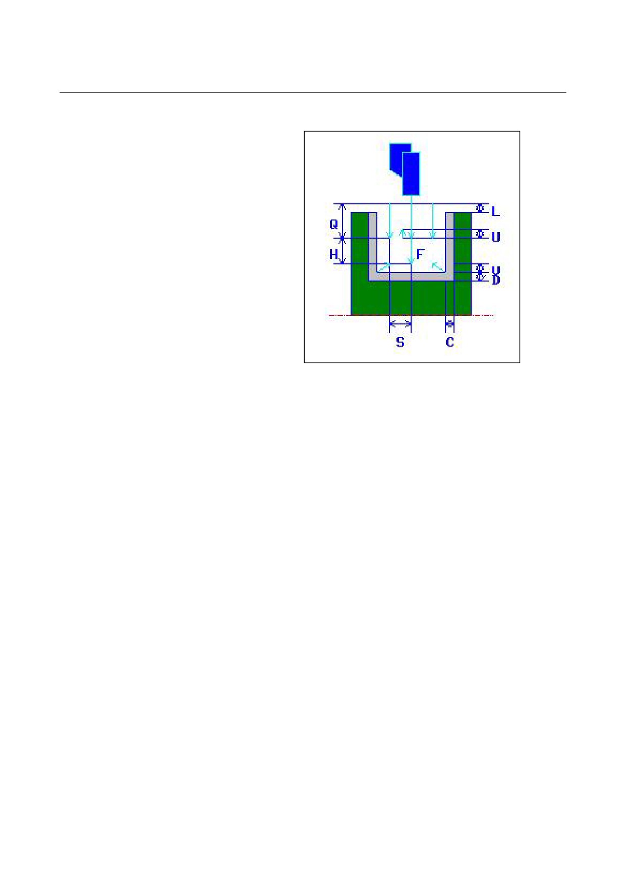
• Tool path
<1> The tool moves to the position "cut-in start point + clearance (L,
M)" by rapid traverse.
<2> After moving to the center of the groove (in the Z-axis direction)
by rapid traverse, the tool cuts in in the X-axis direction at the
feedrate
(F) specified for the cutting direction. If pecking is
specified, the tool cuts a specified pecking amount while
retracting in the +X-axis direction between pecking cycles.
<3> When the tool reaches the groove bottom (but the finishing
allowance) in the X-axis direction, the tool retracts in the
+X-axis direction, shifts by a cut-in amount through the width in
the -Z-axis direction, and then cuts in the X-axis direction.
<4> After step <3> is repeated until one groove wall is reached, the
tool cuts another wall.
<5> After all portions are cut, the tool moves to the position "cut-in
start position + clearance (L)" in the X-axis direction by rapid
traverse.
- 519 -
2.TURNING
CYCLE MACHINING TYPES
B-63874EN/05
Inner surface roughing: G1131
TOOL COND.
Data item
Meaning
R
NOSE RADIUS
Tool nose radius of a grooving tool. (positive
value)
B
TOOL WIDTH
Tool width of a grooving tool (radius value,
positive value)
J
IMAGINARY TOOL NOSE
Imaginary tool nose position of a grooving tool.
NOTE
1 Tab ‘TOOL COND.’ is enabled when bit 0 (TLG) of
parameter No. 27102 = 1.
2 The operator ordinarily sets the above data on the
tab of ‘TOOL DATA’ in Tool Offset window.
Therefore, it is not necessary to display the tab
‘TOOL COND.’
CUT COND.
Data item
Meaning
C*
SIDE FINISH AMOUNT
Finishing allowance for the side faces of a groove.
The blank is regarded as 0. (radius value, positive
value)
D*
BOTTOM FINISH AMT.
Finishing allowance for the bottom of a groove. The
blank is regarded as 0. (radius value, positive value)
F
FEED RATE
Feedrate for cutting in the tool axis direction
(positive value)
W
PECKING
[NOTHIN] : Does not perform pecking in cutting for
grooving (initial value).
[PECKIN] : Performs pecking in cutting for
grooving.
Q
PECKING CUT DEPTH
Depth of cut in the tool axis direction per pecking
operation (radius value, positive value)
Remark) This data item is indicated only when
[PECKIN] is selected for PECKING.
H
RATE OF CUT DEPTH
Change rate for the depth of cut. Specify a change
rate in steps of 1%. A second depth of cut and
subsequent ones are sequentially multiplied by a
specified change rate. (1 to 200, positive value)
(COPY)
- 520 -
B-63874EN/05
CYCLE MACHINING TYPES
2.TURNING
CUT COND.
Data item
Meaning
U*
ESCAPE AMOUNT
Distance by which the tool retracts from a cutting
surface after each cut by pecking.
(radius value,
positive value)
(COPY)
DETAIL
Data item
Meaning
L
CLEARANCE
Distance between the top surface of a groove and a
machining start point (approach point) in the Z-axis
direction (radius value, positive value)
Remark) By referring to the parameter No. 27176
(minimum clamp value), the system sets
the data as an initial value.
P
DWELL
Dwell time applicable when the tool reaches the
bottom of a groove. (in seconds, positive value)
(COPY)
Z
APROCH MOTION
[Z→X]
: From the current position to the
machining start point, the tool moves in
the Z-axis direction and then in the
X-axis direction.
[X→Z]
: From the current position to the
machining start point, the tool moves in
the Z-axis direction and then in the
X-axis direction. (initial value)
[2 AXES]
: From the current position to the
machining start point, the tool moves
simultaneously in the X- and Z-axis
directions.
S
CUT DEPTH FOR WIDTH
Depth of each cut in the grooving tool width direction
(radius value, positive value)
(COPY)
V*
ESCAPE AMOUNT
Distance by which the tool retracts from a cutting
surface after each cut. The blank is regarded as 0.
(radius value, positive value)
Remark) By referring to the parameter No. 27177
(minimum clamp value), the system sets
the data as an initial value.
A
CUT DEPTH DIRECTION
As to X axis Cut direction,
[-X]
: Cuts in the -X direction.
[+X]
: Cuts in the +X direction.
Remark) This data item is enable when the
parameter No.27100#0 = 1.
(COPY)
- 521 -