FANUC MANUAL GUIDE i. OPERATOR’S MANUAL - page 17
1.MILLING
CYCLE MACHINING TYPES
B-63874EN/05
1.7.3
Fixed Form Figure Blocks for Grooving (YZ Plane, XC Plane)
The same fixed-figure block types as for the XY plane explained in
the previous subsection are available for the YZ plane and the XC
plane (polar coordinate interpolation plane). They are provided with
the following G codes.
The data to be set for the YZ and XC planes is the same as for the XY
plane except that the XY plane is changed to the YZ or XC plane and
that the direction in which the tool moves to cut is changed to the
X-axis (YZ plane) or the Z-axis (XC plane).
Square
: G1320 (YZ plane)
Circle
: G1321 (YZ plane)
Track
: G1322 (YZ plane)
Radial groove : G1323 (YZ plane)
Square
: G1520 (XC plane, polar coordinate interpolation plane)
Circle
: G1521 (XC plane, polar coordinate interpolation plane)
Track
: G1522 (XC plane, polar coordinate interpolation plane)
Radial groove : G1523 (XC plane, polar coordinate interpolation plane)
NOTE
When performing machining (polar coordinate
interpolation) on the XC plane, note the following:
(When bit 2 of parameter No. 27000 = 0)
The mode needs to be switched to the polar
coordinate interpolation mode beforehand.
Specifically, enter G12.1 before the machining
type.
Enter G13.1 for canceling polar coordinate
interpolation as required.
(When bit 2 of parameter No. 27000 = 1)
G12.1 and G13.1 are automatically output before
and after cycle machining, respectively.
- 462 -
B-63874EN/05
CYCLE MACHINING TYPES
1.MILLING
1.7.4
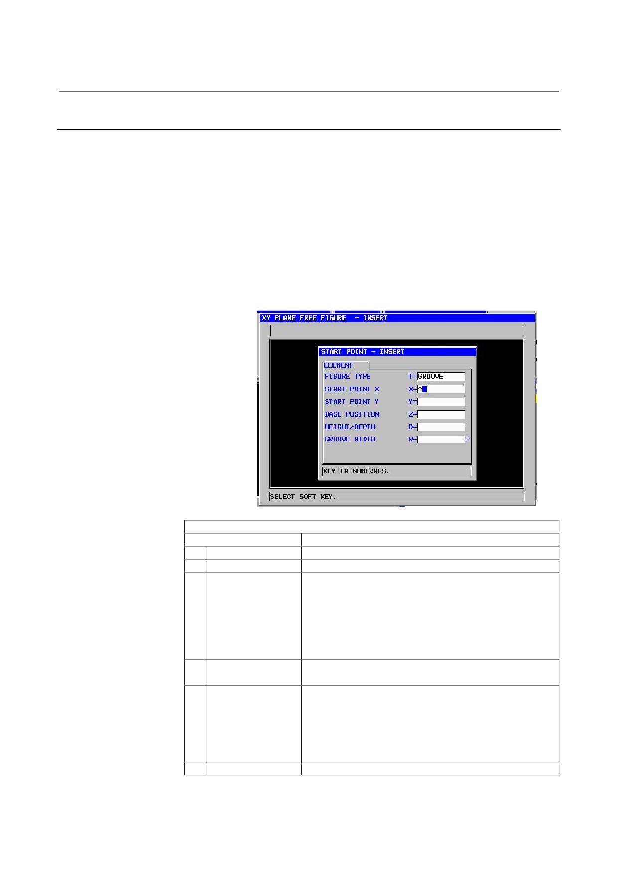
Arbitrary Figure Blocks for Grooving (XY Plane)
When an arbitrary figure for grooving is input, data such as a figure type
and machining reference position is specified in the start point block.
Other data items to be input such as a straight line and arc are exactly the
same as for arbitrary figures of other machining types.
So, this subsection describes only the start point block of an arbitrary
figure for pocketing.
For other arbitrary figures, see Chapter
5, "DETAILED
DESCRIPTIONS ABOUT ENTERING ARBITRARY FIGURES", in
Part II.
When an arbitrary figure is specified for grooving, a groove with a
specified width is cut along the arbitrary figure line.
Start point: G1200 (XY plane)
ELEMENT
Data item
Meaning
X
START POINT X
X coordinate of the start point of an arbitrary figure
Y
START POINT Y
Y coordinate of the start point of an arbitrary figure
T
FIGURE TYPE
[FACE]
: Used as a figure for facing
[CONVEX]
: Used as an outer figure for contouring
[CONCAVE] : Used as an inner figure for contouring or as a
figure for pocketing
[GROOVE] : Used as a figure for grooving
Remark) When grooving is selected as machining type, be
sure to select [GROOVE].
B
BASE POSITION
Z coordinate of the bottom of a groove or the top surface of
a workpiece subject to grooving (in the tool axis direction)
L
HEIGHT/DEPTH
When the top surface of a workpiece is selected as the
BASE POSITION, specify the distance to the bottom of the
groove by using a negative value (radius value). → Depth
When the bottom of a groove is selected as the BASE
POSITION, specify the distance to the top surface of the
groove by using a positive value (radius value). → Height
D
GROOVE WIDTH
Groove width (radius value, positive value)
- 463 -
1.MILLING
CYCLE MACHINING TYPES
B-63874EN/05
1.7.5
Arbitrary Figure Blocks for Grooving (YZ Plane, XC Plane, ZC
Plane, XA Plane)
The same arbitrary-figure block types as for the XY plane explained
in the previous subsection are available for the YZ plane, the XC
plane (polar coordinate interpolation plane), ZC plane and XA plane
(cylindrical surface). Their start points are specified with the
following G codes.
The data to be set for the YZ, XC, ZC, XA planes is the same as for
the XY plane except that the XY plane is changed to the YZ, XC, ZC
or XA plane and that the direction in which the tool moves to cut is
changed to the X-axis (YZ and ZC planes) or the Z-axis (XC and XA
plane).
Start point : G1300 (YZ plane)
Start point : G1500 (XC plane, polar coordinate interpolation plane)
Start point : G1600 (ZC plane, cylindrical surface)
Start point : G1700 (XA plane, cylindrical surface)
NOTE
1
When performing machining (polar coordinate
interpolation) on the XC plane, note the following:
(When bit 2 of parameter No. 27000 = 0)
The mode needs to be switched to the polar
coordinate interpolation mode beforehand.
Specifically, enter G12.1 before the machining
type.
Enter G13.1 for canceling polar coordinate
interpolation as required.
(When bit 2 of parameter No. 27000 = 1)
G12.1 and G13.1 are automatically output before
and after cycle machining, respectively.
2
When performing machining (cylindrical
interpolation) on the ZC and XA plane, note the
following:
(When bit 3 of parameter No. 27000 = 0)
The mode needs to be switched to the cylindrical
coordinate interpolation mode beforehand.
Specifically, enter G07.1C (cylinder radius) before
the machining type.
Enter G07.1C0 for canceling cylindrical
interpolation as required.
(When bit 3 of parameter No. 27000 = 1)
G07.1C (cylinder radius) and G07.1C0 are
automatically output before and after cycle
machining, respectively.
3
The following parameter setting is necessary to
execute XA plane cycle.
• No.27003#2=1, 27003#1=0 and 27003#0=0
- 464 -
B-63874EN/05
CYCLE MACHINING TYPES
1.MILLING
1.8
C-AXIS GROOVING
1.8.1
Machining Type Blocks for C-axis Grooving
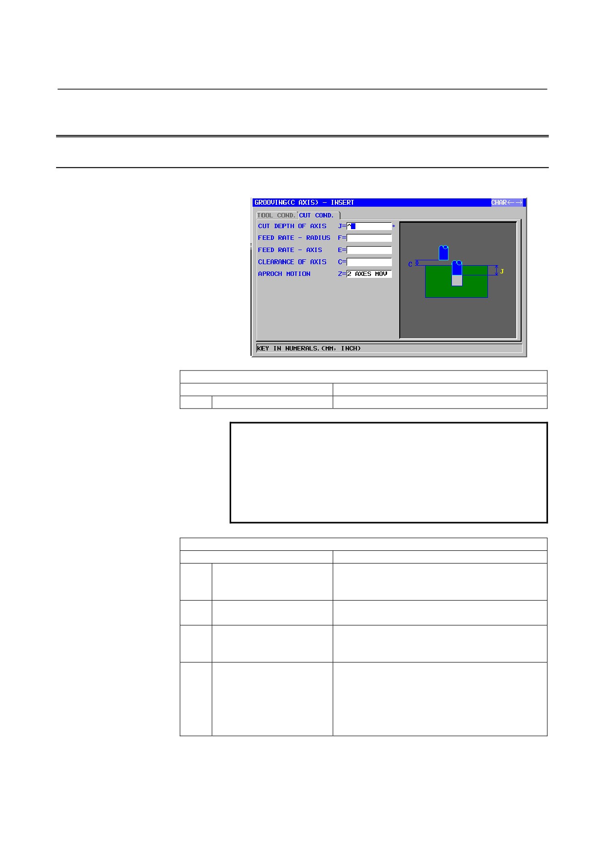
Roughing: G1056
TOOL COND.
Data item
Meaning
D
TOOL DIAMETER
End mill diameter
NOTE
1 Tab ‘TOOL COND.’ is enabled when bit 0 (TLG) of
parameter No. 27002 = 1.
2 The operator ordinarily sets the above data on the
tab of ‘TOOL DATA’ in Tool Offset window.
Therefore, it is not necessary to display the tab
‘TOOL COND.’
CUT COND.
Data item
Meaning
J*
CUT DEPTH OF AXIS
Depth of cut in the tool axis direction per cutting
operation. By default, one cutting operation is
used. (radius value, positive value)
F
FEED RATE- RADIUS
Feedrate applicable when cutting is performed in
the side face direction of the end mill
E
FEEDRATE - AXIS
Feedrate applicable when cutting is performed in
the tool axis direction toward the bottom of a side
face being machined
C
CLEARANCE OF AXIS
Distance between the surface of a blank being
machined and a cutting start point (point R) in the
tool axis direction (radius value, positive value)
Remark) By referring to the parameter No.27009
(minimum clamp value), the system sets
the data as Initial value.
- 465 -

1.MILLING
CYCLE MACHINING TYPES
B-63874EN/05
CUT COND.
Data item
Meaning
Z
APROCH MOTION
[2 AXES]
: When moving from the current
position to the machining start point,
the tool first moves in the machining
plane in two-axis synchronous
operation and then moves along the
tool axis. (initial value)
[3 AXES]
: The tool moves from the current
position to the machining start point in
three-axis synchronous operation.
- 466 -

B-63874EN/05
CYCLE MACHINING TYPES
1.MILLING
1.8.2
Figure Blocks for C-axis Grooving and A-axis Grooving
As C-axis grooving figures, a "C-axis groove on the polar coordinate
plane (XC plane)", "X-axis groove on the polar coordinate plane (XC
plane)", "C-axis groove on the cylindrical surface (ZC plane)", "A-axis
groove on the cylindrical surface (XA plane)", "Z-axis groove on the
cylindrical surface (ZC plane)" and "X-axis groove on the cylindrical
surface (XA plane)" are available. When any of these figures is specified,
a groove with the diameter as large as the end mill diameter is cut.
In C-axis grooving, in-feed cutting in the tool axis direction is performed,
but in-feed cutting in the width direction is not performed.
NOTE
C-axis grooving uses neither polar coordinate
interpolation nor cylinder interpolation. So, it is
unnecessary to switch to the polar coordinate
interpolation or cylinder interpolation mode.
- 467 -
1.MILLING
CYCLE MACHINING TYPES
B-63874EN/05
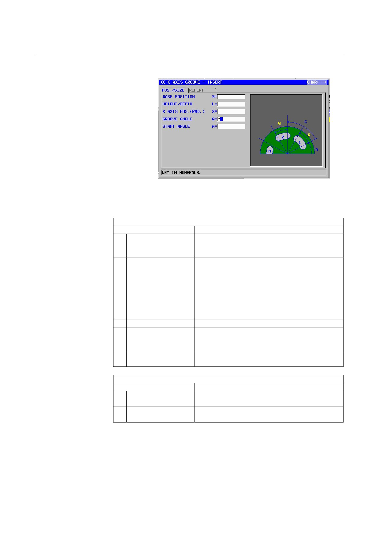
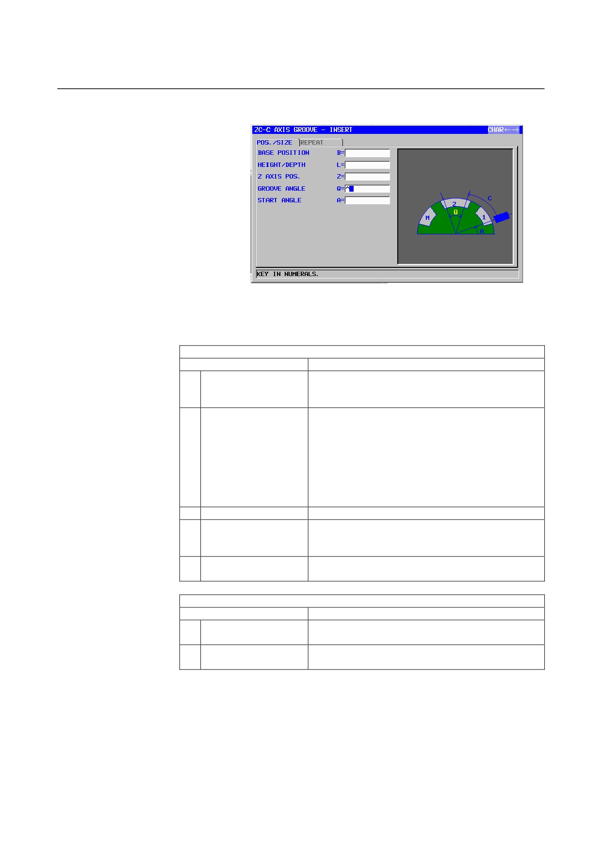
C-axis groove: G1570 (XC plane, end face)
On the end face of a workpiece, circular grooves are cut by rotating the
C-axis with the X-axis position of the tool fixed. Multiple grooves of the
same figure can be cut.
POS./SIZE
Data item
Meaning
B
BASE POSITION
Z coordinate of the bottom of a groove or the top
surface of a workpiece subject to grooving (in the tool
axis direction)
L
HEIGHT/DEPTH
When the top surface of a workpiece is selected as the
BASE POSITION, specify the distance to the bottom of
the groove by using a negative value (radius value).
→ Depth
When the bottom of a groove is selected as the BASE
POSITION, specify the distance to the top surface of the
groove by using a positive value (radius value).
→ Height
X
X AXIS POS.(RAD.)
X coordinate of the center line of a groove (radius value)
Q
GROOVE ANGLE
Center angle formed by the start point (tool center) and
end point (tool center) of a groove (positive or negative
value)
A
START ANGLE
C coordinate of the start point (tool center) of the first
groove
REPEAT
Data item
Meaning
C*
PITCH ANGLE
Center angle formed by the start points (tool centers) of
two adjacent grooves (positive or negative value)
M
GROOVE NUMBER
Number of grooves to be cut (positive value)
*
- 468 -
B-63874EN/05
CYCLE MACHINING TYPES
1.MILLING
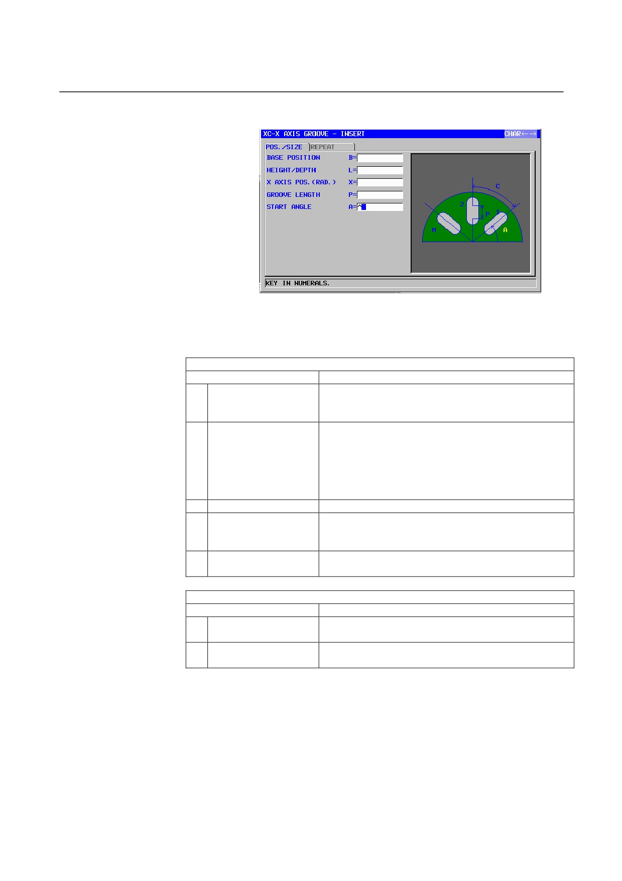
X-axis groove: G1571 (XC plane, end face)
On the end face of a workpiece, radial grooves are cut by moving the tool
in the X-axis direction with the C-axis position fixed. Multiple grooves of
the same figure can be cut.
POS./SIZE
Data item
Meaning
B
BASE POSITION
Z coordinate of the bottom of a groove or the top surface
of a workpiece subject to grooving (in the tool axis
direction)
L
HEIGHT/DEPTH
When the top surface of a workpiece is selected as the
BASE POSITION, specify the distance to the bottom of the
groove by using a negative value (radius value). → Depth
When the bottom of a groove is selected as the BASE
POSITION, specify the distance to the top surface of the
groove by using a positive value (radius value). → Height
X
X AXIS POS.(RAD.)
X coordinate of the start point of a groove (radius value)
P
GROOVE LENGTH
Distance between the start point (tool center) and end
point (tool center) of a groove (radius value,
positive/negative value)
A
START ANGLE
C coordinate of the start point (tool center) of the first
groove
REPEAT
Data item
Meaning
C*
PITCH ANGLE
Center angle formed by the start points (tool centers) of
two adjacent grooves (positive or negative value)
M
GROOVE NUMBER
Number of grooves to be cut (positive value)
*
- 469 -
1.MILLING
CYCLE MACHINING TYPES
B-63874EN/05
C-axis groove: G1670 (cylindrical surface)
On the peripheral surface of a workpiece, grooves are cut by rotating the
C-axis with the Z-axis position of the tool fixed. Multiple grooves of the
same figure can be cut.
POS./SIZE
Data item
Meaning
B
BASE POSITION
X coordinate of the bottom of a groove or the top
surface of a workpiece subject to grooving (in the tool
axis direction)
L
HEIGHT/DEPTH
When the top surface of a workpiece is selected as the
BASE POSITION, specify the distance to the bottom of
the groove by using a negative value (radius value).
→ Depth
When the bottom of a groove is selected as the BASE
POSITION, specify the distance to the top surface of the
groove by using a positive value (radius value).
→ Height
Z
Z AXIS POS.
Z coordinate of the center line of a groove
Q
GROOVE ANGLE
Center angle formed by the start point (tool center) and
end point (tool center) of a groove (positive or negative
value)
A
START ANGLE
C coordinate of the start point (tool center) of the first
groove
REPEAT
Data item
Meaning
C*
PITCH ANGLE
Center angle formed by the start points (tool centers) of
two adjacent grooves (positive or negative value)
M
GROOVE NUMBER
Number of grooves to be cut (positive value)
*
- 470 -
B-63874EN/05
CYCLE MACHINING TYPES
1.MILLING
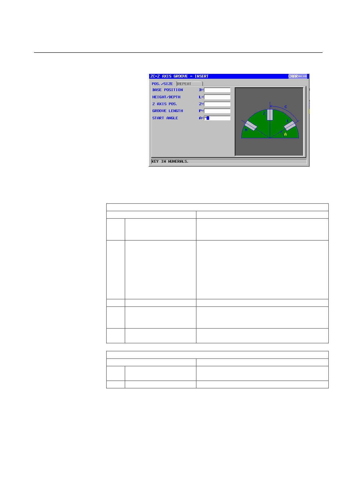
Z-axis groove: G1671 (cylindrical surface)
On the peripheral surface of a workpiece, straight grooves are cut by
moving the tool in the Z-axis direction with the C-axis position fixed.
Multiple grooves of the same figure can be cut.
POS./SIZE
Data item
Meaning
B
BASE POSITION
X coordinate of the bottom of a groove or the top
surface of a workpiece subject to grooving (in the
tool axis direction)
L
HEIGHT/DEPTH
When the top surface of a workpiece is selected as
the BASE POSITION, specify the distance to the
bottom of the groove by using a negative value
(radius value). → Depth
When the bottom of a groove is selected as the
BASE POSITION, specify the distance to the top
surface of the groove by using a positive value
(radius value). → Height
Z
Z AXIS POS.
Z coordinate of the start point of a groove
P
GROOVE LENGTH
Distance between the start point (tool center) and
end point (tool center) of a groove (radius value,
positive/negative value)
A
START ANGLE
C coordinate of the start point (tool center) of the first
groove
REPEAT
Data item
Meaning
C*
PITCH ANGLE
Center angle formed by the start points (tool centers)
of two adjacent grooves (positive or negative value)
M*
GROOVE NUMBER
Number of grooves to be cut (positive value)
- 471 -

1.MILLING
CYCLE MACHINING TYPES
B-63874EN/05
1.9
REAR END FACING BY MILLING
1.9.1
Rear End Facing
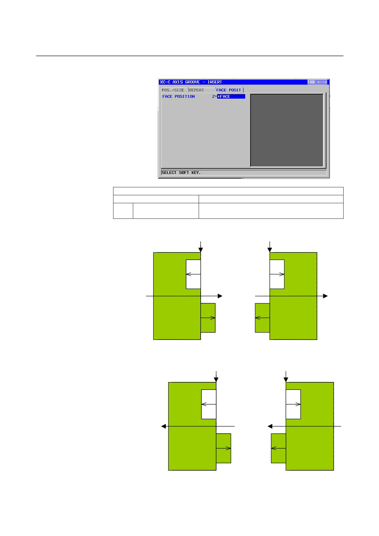
By setting bit 4 of parameter No. 27000 to 1, the input item "FACE
POSITION" is displayed on the figure menu for milling below. By
entering this data, rear end facing is enabled.
1.
Arbitrary-figure (XY plane) - Start point : G1200
2.
Hole position (XY plane) - Random points : G1210
3.
Hole position (XY plane) - Linear points (same interval) : G1211
4.
Hole position (XY plane) - Linear points (different interval) :
G1212
5.
Hole position (XY plane) - Grid points : G1213
6.
Hole position (XY plane) - Rectangle points : G1214
7.
Hole position (XY plane) - Circle points : G1215
8.
Hole position (XY plane) - Arc points (same interval): G1216
9.
Hole position
(XY plane) - Arc points (different interval)
:
G1217
10.
Fixed-figure (XY plane) - Rectangle : G1220
11.
Fixed-figure (XY plane) - Circle : G1221
12.
Fixed-figure (XY plane) - Track : G1222
13.
Fixed-figure (XY plane) - Radial groove : G1223
14.
Arbitrary-figure (XC plane) - Start point : G1500
15.
Fixed-figure (XC plane) - Rectangle : G1520
16.
Fixed-figure (XC plane) - Circle : G1521
17.
Fixed-figure (XC plane) - Track : G1522
18.
Fixed-figure (XC plane) - Radial groove : G1523
19.
C-axis groove on the polar coordinate plane: G1570
20.
X-axis groove on the polar coordinate plane : G1571
21.
C-axis hole on the polar coordinate plane (circle points) : G1572
22.
C-axis hole on the polar coordinate plane
(random points) :
G1573
- 472 -
B-63874EN/05
CYCLE MACHINING TYPES
1.MILLING
Example) C-axis groove on the polar coordinate plane: G1570
FACE POSIT
Data item
Meaning
Z
FACE POSITION
[+FACE ]: References the figure below (+ end face).
[-FACE ]: References the figure below (- end face).
Reference position
Reference position
(-)
Depth
Depth
(-)
+Z
+Z
(+)
Height
Height
(+)
+ end face
- end face
Reference position
Reference position
(-)
Depth
Depth
(-)
+Z
+Z
(+)
Height
Height
(+)
- end face
+ end face
- 473 -

1.MILLING
CYCLE MACHINING TYPES
B-63874EN/05
1.10
ADDRESS SETTING OF ROTATION AXIS
1.10.1
Support for C-Axis Machining with Rotation Axis
By setting bit
0 of parameter No.
27001 to
1, the input item
"ROTATION AXIS NAME" is displayed on the figure menu for
milling below. By entering this data, C-axis machining using a
rotation axis is enabled.
1.
Rectangle on the polar coordinate plane: G1520
2.
Circle on the polar coordinate plane : G1521
3.
Track on the polar coordinate plane : G1522
4.
Radial groove on the polar coordinate plane : G1523
5.
C-axis groove on the polar coordinate plane: G1570
6.
X-axis groove on the polar coordinate plane: G1571
7.
C-axis hole on the polar coordinate plane (circle points) : G1572
8.
C-axis hole on the polar coordinate plane
(random points) :
G1573
9.
C-axis groove on the cylindrical surface : G1670
10. X-axis groove on the cylindrical surface : G1671
11. C-axis hole on the cylindrical surface (circle points) : G1672
12. C-axis hole on the cylindrical surface (random points) : G1673
13. Arbitrary-figure on the end face : G1500
13. Arbitrary-figure on the cylindrical surface : G1600
- 474 -
B-63874EN/05
CYCLE MACHINING TYPES
1.MILLING
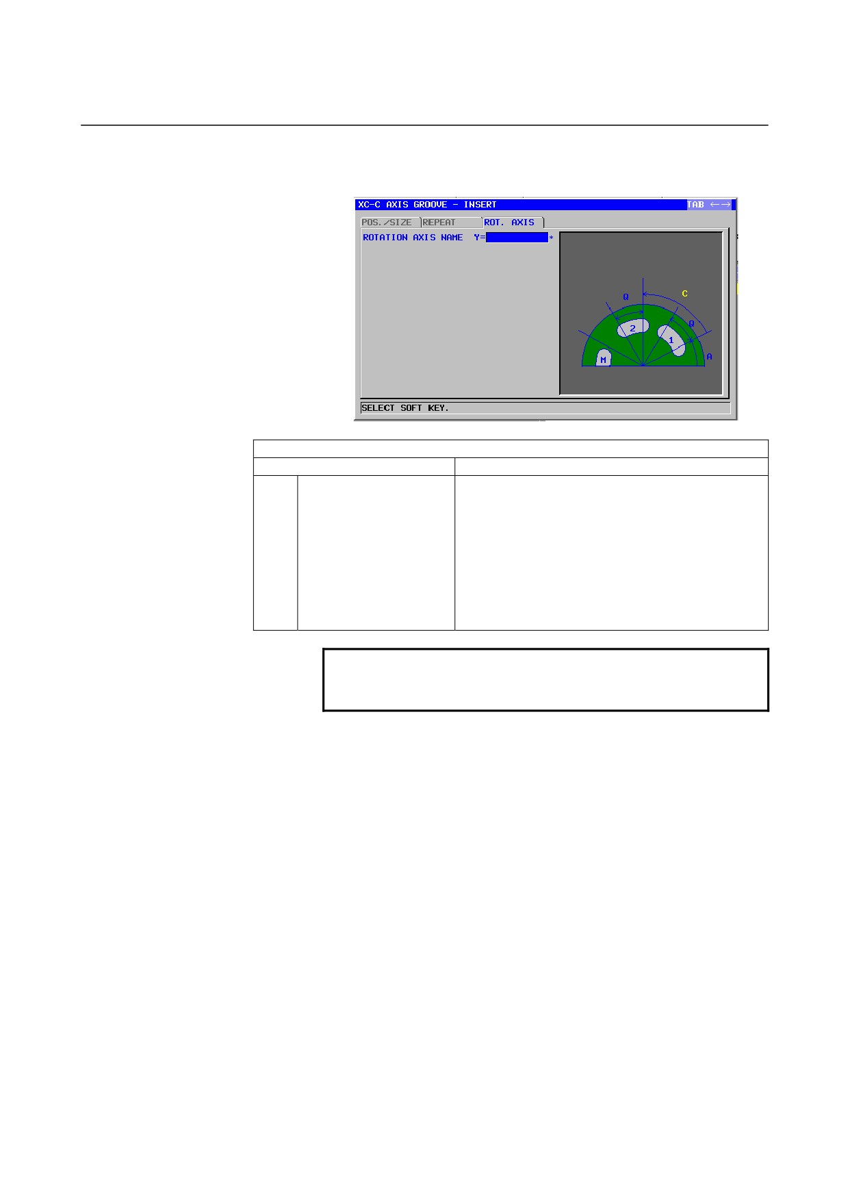
Example) C-axis groove on the polar coordinate plane: G1570
ROT. AXIS
Data item
Meaning
Y
ROTATION AXIS NAME
When bit 1 of parameter No. 27001 #1 = 1
[C]: The rotation axis is the C-axis.
[A]: The rotation axis is the A-axis.
When bit 2 of parameter No. 27001 #2 = 1
[C]: The rotation axis is the C-axis.
[B]: The rotation axis is the B-axis.
When bit 3 of parameter No. 27001 #3 = 1
[C]: The rotation axis is the C-axis.
[E]: The rotation axis is the E-axis.
NOTE
This data item is enabled when the parameter
No.27001#0 = 1.
- 475 -
1.MILLING
CYCLE MACHINING TYPES
B-63874EN/05
1.11
C AXIS CLAMPING M CODE OUTPUT
1.11.1
Outline
C axis clamping and unclamping M codes are automatically output in
C axis cycles as followings, which position C axis in the cycle motion.
* C axis represents a rotating axis around Z axis in this
specifications.
(1) Hole machining cycles
In hole machining cycles combined with following figures, C
axis clamping and unclamping M codes are automatically output.
a) C-axis hole on the end face
: G1572
b) C-axis hole on the end face (arbitrary)
: G1573
c) C-axis hole on the cylindrical surface (arbitrary) : G1672
d) C-axis hole on the cylindrical surface (arbitrary) : G1673
(2) Grooving cycles
In grooving cycles combined with following figures, C axis
clamping and unclamping M codes are automatically output.
a) X-axis groove on the end face : G1571
b) Z-axis groove on the cylindrical surface : G1671
1.11.2
Value of M Code Output
M code set in following parameters are output
When zero is set, M code is not output.
(1) C axis clamping M code for main spindle
: Parameter No.27005
(2) C axis unclamping M code for main spindle : Parameter No.27006
(3) C axis clamping M code for sub spindle
: Parameter No.27011
(4) C axis unclamping M code for sub spindle
: Parameter No.27012
- 476 -
B-63874EN/05
CYCLE MACHINING TYPES
1.MILLING
1.11.3 Distinction between Main and Sub Spindle
When an axis name “C” is specified in figure command and no axis
name is specified, M code set in parameter No.27005 or 27006 for
main spindle is output.
When an axis name “A”, “B”, or “E” is specified in figure command,
M code set in parameter No.27011 or 27012 for sub spindle is output.
1.11.4
Position of M Code Output
(1)
Hole machining cycle
G90
G17
Mb
*1
G00 X(x1) C(c1) Z(I point)
G99
G81 Z(depth) R(R point) F(feed) Ma
*1
Mb
X(x2) C(c2) Ma
*1
Mb
X(x3) C(c3) Ma
*1
Mb
G80
G00 Z(I point)
*1 Ma means C axis clamping M code, Mb means C axis
unclamping one.
a, b should be set in parameters No.27005, No.27006,
No.27011 and No.27012.
When value of the parameter is zero, no M code is output.
(2)
Grooving Cycle
a) X-axis groove on the end face : G1571
G1056J10.C2.F100.E100.Z2
C axis grooving cycle command
G1571B0.L-10.X40.P20.A0.C120.M2.Z1.Y1.
X-axis groove on the end face
In case above commands are specified, C axis unclamping
M code is output at the beginning of a cycle, C axis
clamping M code is output before cutting motion, and C
axis unclamping M code is output after cutting motion
during a cycle
Mβ
* 1
G17
G0X80.C0.
- 477 -
1.MILLING
CYCLE MACHINING TYPES
B-63874EN/05
G0Z2.
Mα
* 1
G1Z-10.F100.
G1X40.F100.
G1Z2.F100.
Mβ
* 1
G17
G0X80.C120.
G0Z2.
Mα
* 1
G1Z-10.F100.
G1X40.F100.
G1Z2.F100.
Mb
.....................................* 1
*1 Mα means C axis clamping M code, Mβ means C axis
un clamping one.
α, β should be set in parameters No.27005, No.27006,
No.27011 and No.27012.
When value of the parameter is zero, no M code is
output.
b)
Z-axis groove on the cylindrical surface : G1671
G1056J10.C2.F100.E100.Z2.
C axis grooving command
G1671B50.L-10.Z-30.P20.A0.C120.M2.Y1.
Z-axis groove on the cylindrical surface
In case above commands are specified, C axis unclamping
M code is output at the beginning of a cycle, C axis
clamping M code is output before cutting motion, and C
axis unclamping M code is output after cutting motion
during a cycle
Mβ
*1
G19
G0Z-30.C0.
G0X104.
Mα
* 1
G1X80.F100.
G1Z-50.F100.
G1X104.F100.
Mβ
* 1
G19
G0Z-30.C120.
G0X104.
Mα
* 1
G1X80.F100.
G1Z-50.F100.
G1X104.F100.
Mβ
* 1
- 478 -
B-63874EN/05
CYCLE MACHINING TYPES
1.MILLING
*1 Mα means C axis clamping M code, Mβ means C axis
un clamping one.
α, β should be set in parameters No.27005, No.27006,
No.27011 and No.27012. When value of the parameter
is zero, no M code is output.
- 479 -
2.TURNING
CYCLE MACHINING TYPES
B-63874EN/05
2
TURNING
With MANUAL GUIDE i, the cycles motions listed below are available
for turning.
Hole machining (workpiece rotation)
G1100
Center drilling
G1101
Drilling
Machining type block
G1102
Tapping
G1103
Reaming
G1104
Boring
Turning
G1120
Outer surface roughing
G1121
Inner surface roughing
G1122
End face roughing
G1123
Outer surface semifinishing
Machining type block
G1124
Inner surface semifinishing
G1125
End face semifinishing
G1126
Outer surface finishing
G1127
Inner surface finishing
G1128
End face finishing
G1450
Start point
G1451
Straight line
G1452
Arc (CW)
Turning figure block
G1453
Arc (CCW)
(ZX plane)
G1454
Chamfer
G1455
Corner rounding
G1456
End
Turning groove
G1130
Outer surface roughing
G1131
Inner surface roughing
G1132
End face roughing
G1133
Outer surface roughing and finishing
Machining type block
G1134
Inner surface roughing and finishing
G1135
End face roughing and finishing
G1136
Outer surface finishing
G1137
Inner surface finishing
G1138
End face finishing
G1470
Outer normal groove
G1471
Outer trapezoidal groove
Groove figure block
G1472
Inner normal groove
(ZX plane)
G1473
Inner trapezoidal groove
G1474
End face normal groove
G1475
End face trapezoidal groove
- 480 -
B-63874EN/05
CYCLE MACHINING TYPES
2.TURNING
Threading
G1140
Outer surface
Machining type block
G1141
Inner surface
G1460
General-purpose thread
G1461
Metric thread
Thread figure block
G1462
Unified thread
(ZX plane)
G1463
PT thread
G1464
PF thread
NOTE
1
When cycle motions are input with MANUAL
GUIDE i, sets of a machining type block and figure
blocks must be input in succession for all cycle
motions except turning hole machining.
For one machining type block, multiple figure
blocks can be input.
However, multiple sets of arbitrary figures can be
input, with one set including up to 50 figures
enclosed between a start point and end block.
2
For each item marked with [*] in the tables below, a
standard value is automatically set if no value is
input.
The screen displays [*] to the right of a data item.
3
In some of the input data items, the system sets
the last inputed data as an initial data. As to these
input data items, the mark of “(COPY)” was
described.
4
The motions go back to the start point where the
machining cycle started after completing the all
cycle motions.
(It is possible not to go back the satrt point when
the parameter No.27102#7 is set to 1.)
5
Cycle machining cannot be performed in any of
control modes of the high-speed and high-precision
functions (commands for advanced preview
control, AI advanced preview control, AI contour
control, AI nano contour control, high-precision
contour control, AI high-precision contour control,
and AI nano high-precision contour control). To
perform cycle machining, control mode must be
canceled.
6
On the CNC for lathe turning with G-code system B
or C, when cycle machining is specified, G90 must
be specified in advance to make a switchover to
the absolute coordinate system. For hole
machining by turning (with the tool rotated), G98
(initial level return) or G99 (R position level return)
must be specified in advance.
- 481 -
2.TURNING
CYCLE MACHINING TYPES
B-63874EN/05
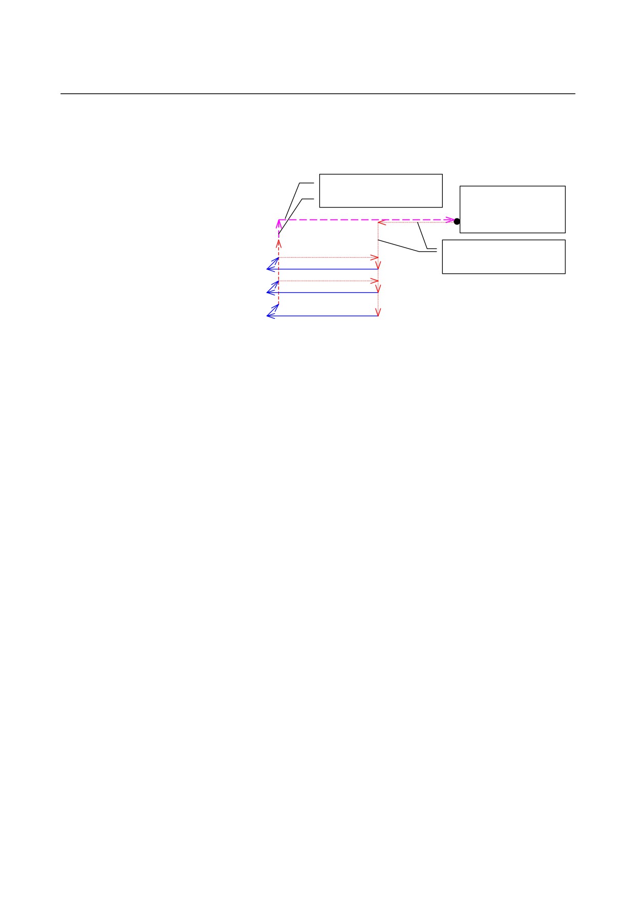
Remarks) Cycle retract motions
In case of No.27102#7=0, Retracting motions indicated as bloken
lines in the following drawing will be outputted. The order of
motion axis will be opposite to the approched motions
Retracting motion of a
machining cycle
Position where the
machining cycle
started
Approaching motions
of a machining cycle
In case of carrying out plural figures machining by one G4 digit
cycle, such like grooving, this retracting motions will be
available at the last figure machining.
- 482 -
B-63874EN/05
CYCLE MACHINING TYPES
2.TURNING
2.1
HOLE MACHINING (WORKPIECE ROTATION)
2.1.1
Machining Type Blocks for Hole Machining (Workpiece
Rotation)
NOTE
Hole machining (workpiece rotation) is performed
only at the center of a workpiece. So, unlike other
cycle motions, figure blocks cannot be specified.
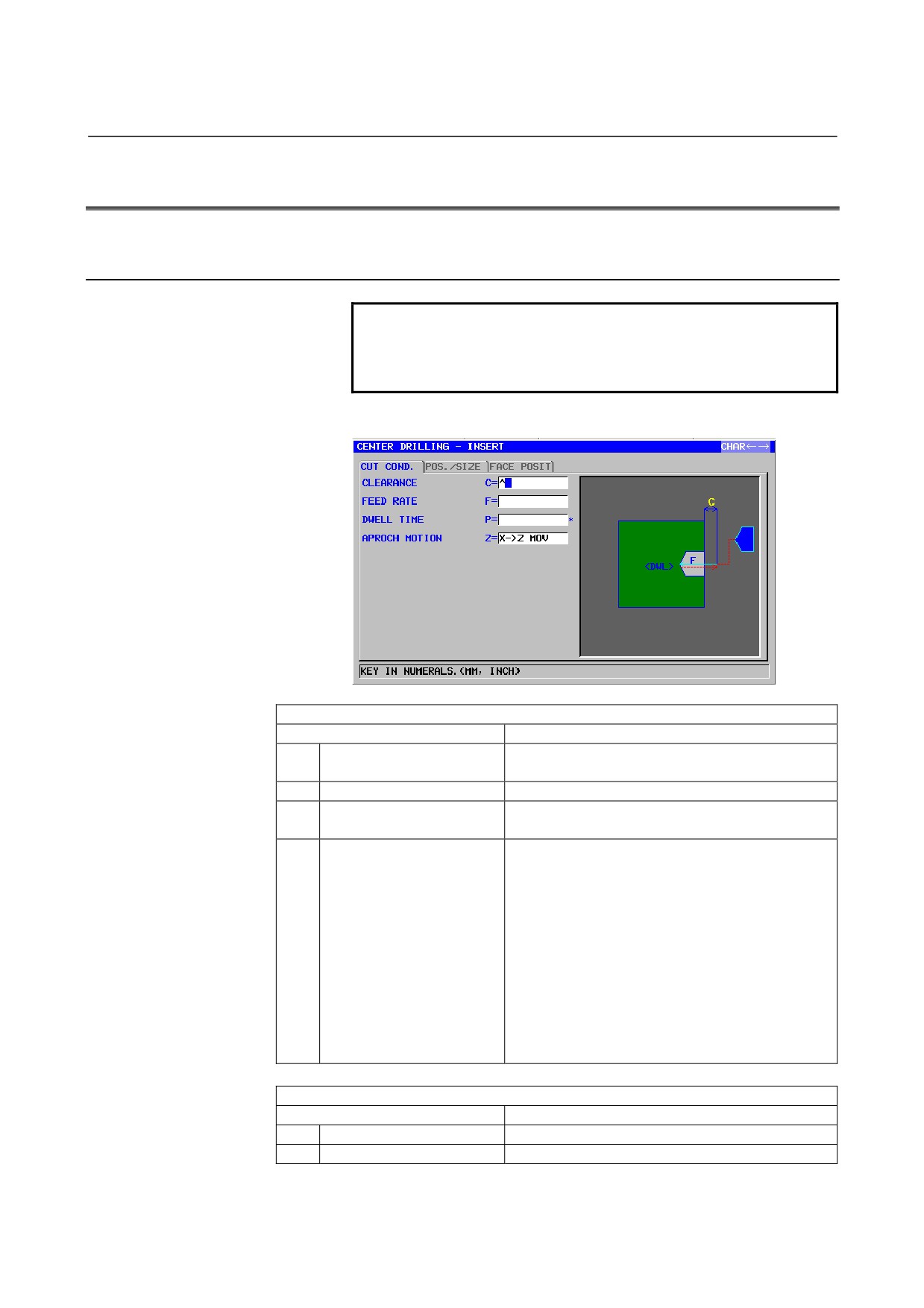
Center drilling: G1100
CUT COND.
Data item
Meaning
C
CLEARANCE
Distance between the surface of a workpiece and
point R (radius value, positive value)
(COPY)
F
FEED RATE
Cutting feedrate (positive value)
(COPY)
P*
DWELL TIME
Dwell time at the bottom of a hole (in seconds,
positive value)
(COPY)
Z
APROCH MOTION
[Z→X]
: From the current position to the
machining start point, the tool moves in
the Z-axis direction and then in the
X-axis direction.
[X→Z]
: From the current position to the
machining start point, the tool moves in
the Z-axis direction and then in the
X-axis direction. (initial value)
[2 AXES] : From the current position to the
machining start point, the tool moves
simultaneously in the X- and Z-axis
directions.
POS./SIZE
Data item
Meaning
B
BASE POSITION
Z coordinate of the surface of a workpiece
L
CUT DEPTH
Hole depth (radius value, negative value)
- 483 -
2.TURNING
CYCLE MACHINING TYPES
B-63874EN/05
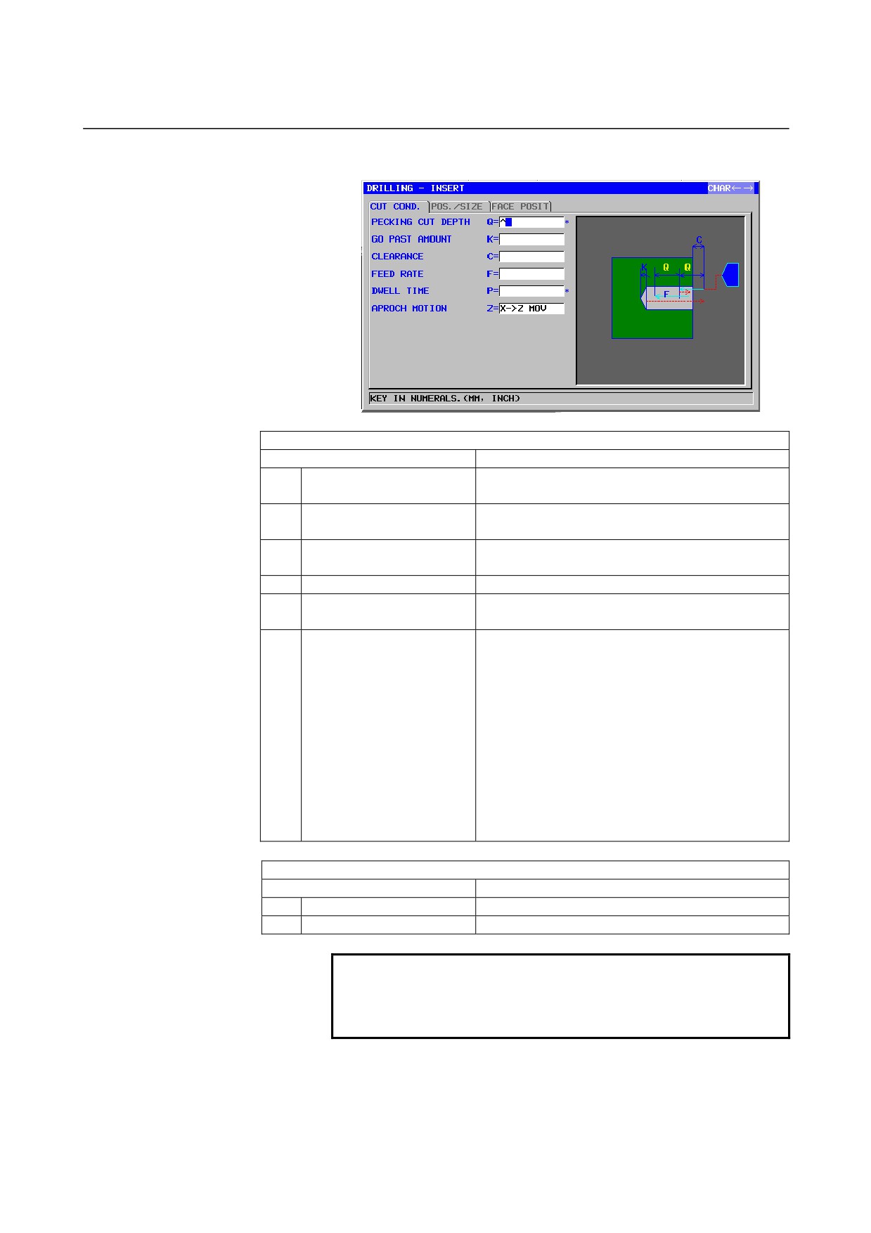
Drilling: G1101
CUT COND.
Data item
Meaning
Q*
PECKING CUT DEPT
Depth of cut per drilling operation (radius value,
positive value)
(COPY)
(Note)
K*
GO PAST AMOUNT
Length of the incomplete hole at the tip of the tool
(radius value, positive value)
(COPY)
C
CLEARANCE
Distance between the surface of a workpiece and
point R (radius value, positive value)
(COPY)
F
FEED RATE
Cutting feedrate (positive value)
(COPY)
P*
DWELL TIME
Dwell time at the bottom of a hole (in seconds)
(COPY)
Z
APROCH MOTION
[Z→X]
: From the current position to the
machining start point, the tool moves in
the Z-axis direction and then in the
X-axis direction.
[X→Z]
: From the current position to the
machining start point, the tool moves in
the Z-axis direction and then in the
X-axis direction. (initial value)
[2 AXES] : From the current position to the
machining start point, the tool moves
simultaneously in the X- and Z-axis
directions.
POS./SIZE
Data item
Meaning
B
BASE POSITION
Z coordinate of the surface of a workpiece
L
CUT DEPTH
Hole depth (radius value, negative value)
NOTE
The system refers to the parameter No.5114 as the
return amount. Therefore, please set No.5114 to
the suitable value before machining.
- 484 -
B-63874EN/05
CYCLE MACHINING TYPES
2.TURNING
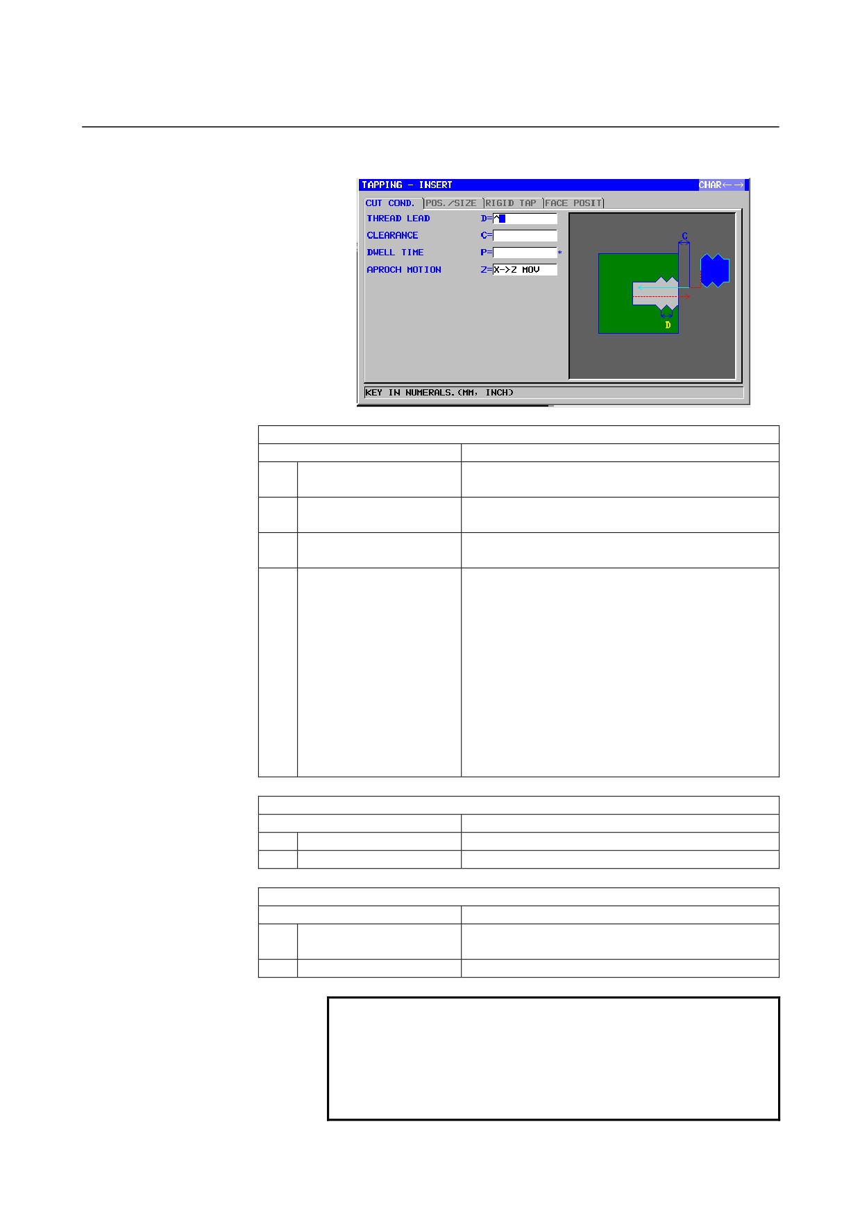
Tapping: G1102
CUT COND.
Data item
Meaning
D
THREAD LEAD
Lead of a tapping tool (radius value, positive value)
(COPY)
C
CLEARANCE
Distance between the surface of a workpiece and
point R (radius value, positive value)
(COPY)
P*
DWELL TIME
Dwell time at the bottom of a hole (in seconds,
positive value)
(COPY)
Z
APROCH MOTION
[Z→X]
: From the current position to the
machining start point, the tool moves in
the Z-axis direction and then in the
X-axis direction.
[X→Z]
: From the current position to the
machining start point, the tool moves in
the Z-axis direction and then in the
X-axis direction. (initial value)
[2 AXES] : From the current position to the
machining start point, the tool moves
simultaneously in the X- and Z-axis
directions.
POS./SIZE
Data item
Meaning
B
BASE POSITION
Z coordinate of the surface of a workpiece
L
CUT DEPTH
Hole depth (radius value, negative value)
RIGID TAP
Data item
Meaning
R
TAP TYPE
[FLOAT]
: Specifies the float tap. (initial value)
[RIGID]
: Specifies the rigid tap. (Note)
S
SPINDLE SPEED
Spindle speed (min-1)
NOTE
When you use the rigid tap M code command
(No.5200#0=0), the system refers to the parameter
No.5210 or No.5212 as M code. Therefore, please
set No.5210 or No.5212 to the suitable value
before machining.
- 485 -
2.TURNING
CYCLE MACHINING TYPES
B-63874EN/05
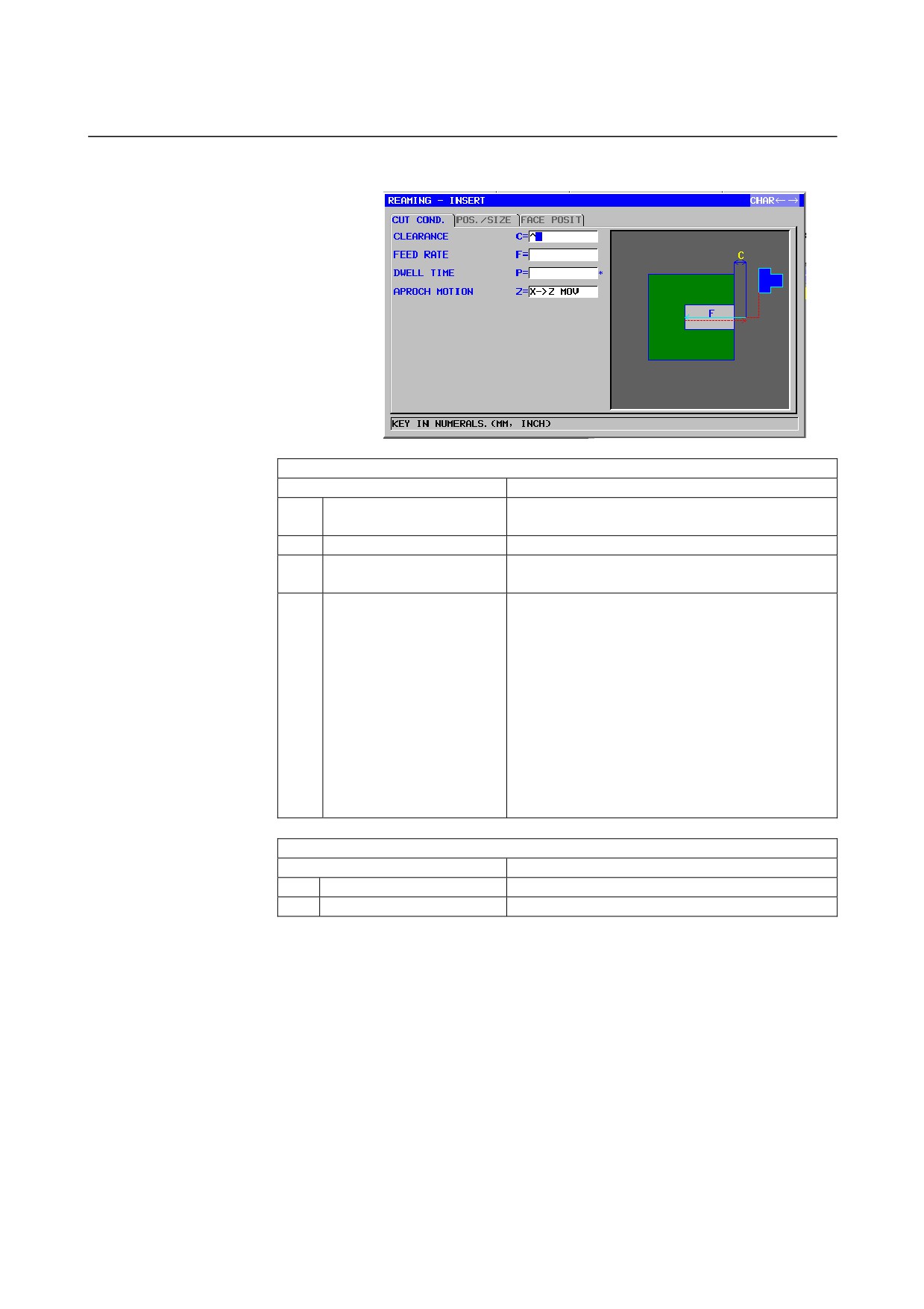
Reaming: G1103
CUT COND.
Data item
Meaning
C
CLEARANCE
Distance between the surface of a workpiece and
point R (radius value, positive value)
(COPY)
F
FEED RATE
Cutting feedrate (positive value)
(COPY)
P*
DWELL TIME
Dwell time at the bottom of a hole (in seconds,
positive value)
(COPY)
Z
APROCH MOTION
[Z→X]
: From the current position to the
machining start point, the tool moves in
the Z-axis direction and then in the
X-axis direction.
[X→Z]
: From the current position to the
machining start point, the tool moves in
the Z-axis direction and then in the
X-axis direction. (initial value)
[2 AXES]: From the current position to the
machining start point, the tool moves
simultaneously in the X- and Z-axis
directions.
POS./SIZE
Data item
Meaning
B
BASE POSITION
Z coordinate of the surface of a workpiece
L
CUT DEPTH
Hole depth (radius value, negative value)
- 486 -
B-63874EN/05
CYCLE MACHINING TYPES
2.TURNING
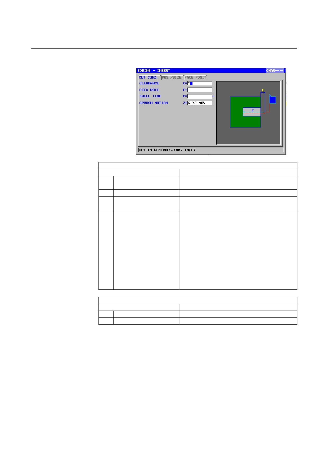
Boring: G1104
CUT COND.
Data item
Meaning
C
CLEARANCE
Distance between the surface of a workpiece and
point R (radius value, positive value)
(COPY)
F
FEED RATE
Cutting feedrate (positive value)
(COPY)
P*
DWELL TIME
Dwell time at the bottom of a hole (in seconds,
positive value)
(COPY)
Z
APROCH MOTION
[Z→X]
: From the current position to the
machining start point, the tool moves in
the Z-axis direction and then in the
X-axis direction.
[X→Z]
: From the current position to the
machining start point, the tool moves in
the Z-axis direction and then in the
X-axis direction. (initial value)
[2 AXES] : From the current position to the
machining start point, the tool moves
simultaneously in the X- and Z-axis
directions.
POS./SIZE
Data item
Meaning
B
BASE POSITION
Z coordinate of the surface of a workpiece
L
CUT DEPTH
Hole depth (radius value, negative value)
- 487 -
2.TURNING
CYCLE MACHINING TYPES
B-63874EN/05
2.2
TURNING
2.2.1
Machining Type Blocks for Turning
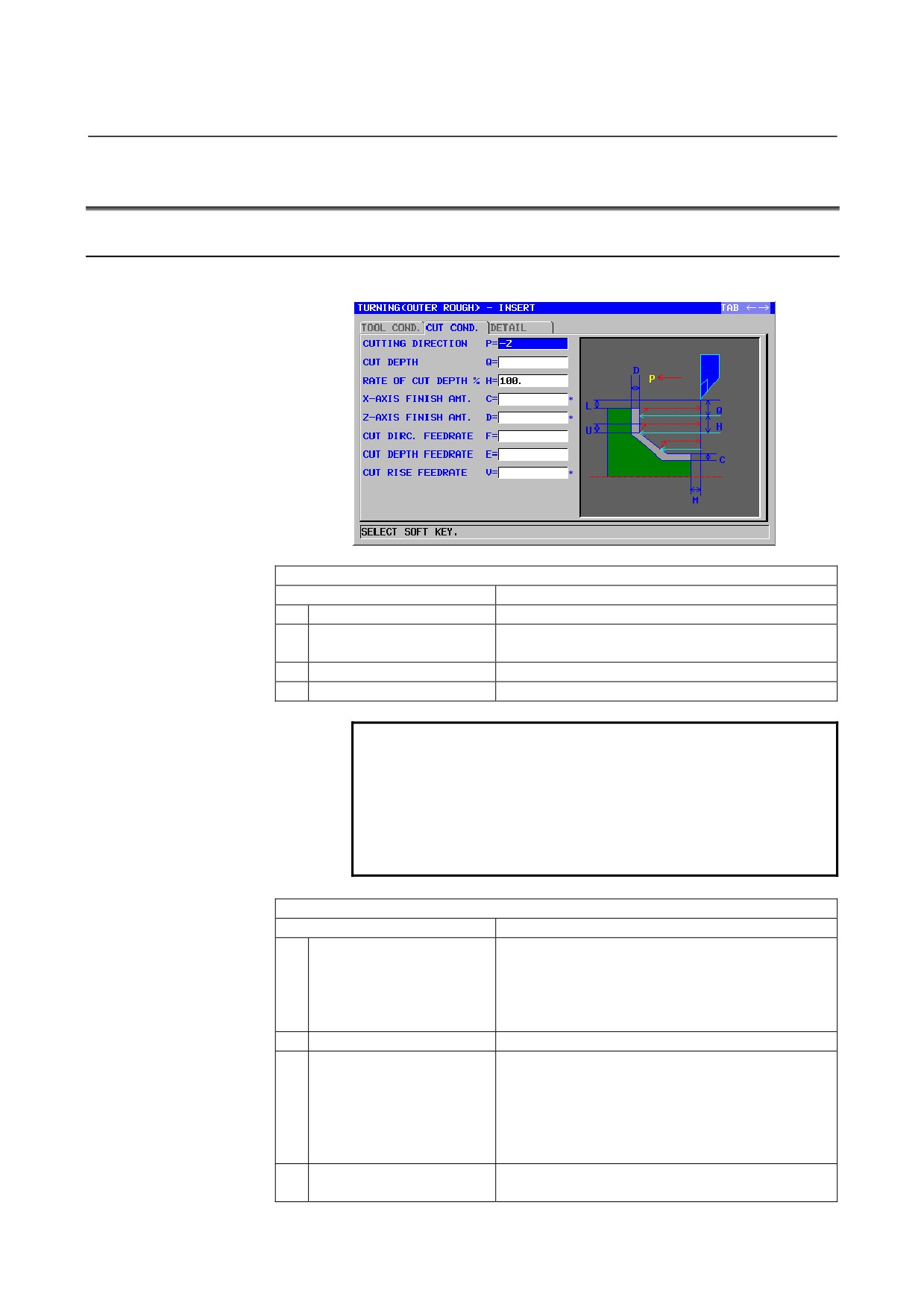
Outer surface roughing: G1120
TOOL COND.
Data item
Meaning
R
NOSE RADIUS
Tool nose radius of a roughing tool (positive value)
A
CUT EDGE ANGLE
Cutting edge angle of a roughing tool (positive
value)
B
NOSE ANGLE
Tool angle of a roughing tool (positive value)
J
IMAGINARY TOOL NOSE
Imaginary tool nose position of a roughing tool
NOTE
1 Tab ‘TOOL COND.’ is enabled when bit 0 (TLG) of
parameter No. 27102 = 1.
2 The operator ordinarily sets the above data on the
tab of ‘TOOL DATA’ in Tool Offset window.
Therefore, it is not necessary to display the tab
‘TOOL COND.’
CUT COND.
Data item
Meaning
P
CUTTING DIRECTION
[-Z]
: Cuts in the -Z direction.
[+Z]
: Cuts in the +Z direction.
Remark) [+Z] is used for cutting in the reverse
direction or for machining with a
subspindle.
(COPY)
Q
CUT DEPTH
Depth of each cut (radius value, positive value)
H
RATE OF CUT DEPTH
Change rate for the depth of cut. Specify a change
rate in steps of 1%. A second depth of cut and
subsequent ones are sequentially multiplied by a
specified change rate. The default is 100%, meaning
that the depth of cut remains unchanged. (1 to 200,
positive value)
C*
X-AXIS FINISH AMT.
Finishing allowance in the X-axis direction. The
blank is regarded as 0. (radius value, positive value)
- 488 -
B-63874EN/05
CYCLE MACHINING TYPES
2.TURNING
CUT COND.
Data item
Meaning
D*
Z-AXIS FINISH AMT.
Finishing allowance in the Z-axis direction. The
blank is regarded as 0. (radius value, positive value)
F
CUT DIRC.FEEDRATE
Feedrate applicable when the tool cuts in the
workpiece radius direction (positive value)
E
CUT DEPTH FEEDRATE
Feedrate applicable when the tool cuts in the Z-axis
direction (positive value)
V
CUT RISE FEEDRATE
Feedrate applicable when the tool cuts up in the
direction of retraction from the workpiece (positive
value)
DETAIL
Data item
Meaning
K
1ST OVERRIDE
Feedrate override value for the first cut. Specify an
override value in steps of 1%. The default is 100%.
(1 - 200, positive value)
Remark) This data item is used, for example, to cut
the black coating of a cast workpiece.
W
CUT RISE METHOD
[SPEED]: The tool retracts by a distance specified
with ESCAPE AMOUNT in the XZ
direction immediately after cutting.
[CUT]
: The tool retracts by a "retract" distance"
after cutting along the figure.
(COPY)
U
ESCAPE AMOUNT
Distance by which the tool retracts from a cutting
surface after each cut (radius value, positive value)
Remark) By referring to the parameter No. 27128
(minimum clamp value), the system sets
the data as an initial value.
L
X-AXIS CLEARANCE
Distance between a blank and machining start point
(approach point) in the X-axis direction (radius
value, positive value)
Remark) By referring to the parameter No. 27129
(minimum clamp value), the system sets
the data as an initial value.
M
Z-AXIS CLEARANCE
Distance between a blank and machining start point
(approach point) in the Z-axis direction (radius value,
positive value)
Remark) By referring to the parameter No. 27130
(minimum clamp value), the system sets
the data as an initial value.
Z
APROCH MOTION
[Z→X]
: From the current position to the
machining start point, the tool moves in
the Z-axis direction and then in the
X-axis direction. (initial value)
[X→Z]
: From the current position to the
machining start point, the tool moves in
the Z-axis direction and then in the
X-axis direction.
[2 AXES]
: From the current position to the
machining start point, the tool moves
simultaneously in the X- and Z-axis
directions.
- 489 -
2.TURNING
CYCLE MACHINING TYPES
B-63874EN/05
DETAIL
Data item
Meaning
S
CUT DEPTH DIRECTION
As to X axis Cut direction,
[-X]
: Cuts in the -X direction.
[+X]
: Cuts in the +X direction.
Remark) This data item is enable when the
parameter No.27100#0 = 1.
(COPY)
X
POCKET CUTTING
[CUT]
: Cuts a pocket. (initial value)
[NOTHIN] : Does not cut a pocket.
Remark) This data item is enable when the
parameter No.27100#1 = 1.
Y
OVERHANG CUTTING
[CUT]
: Cuts an overhang. (initial value)
[NOTHIN] : Does not cut an overhang.
Remark) This data item is enable when the
parameter No.27100#1 = 1.
- 490 -
B-63874EN/05
CYCLE MACHINING TYPES
2.TURNING
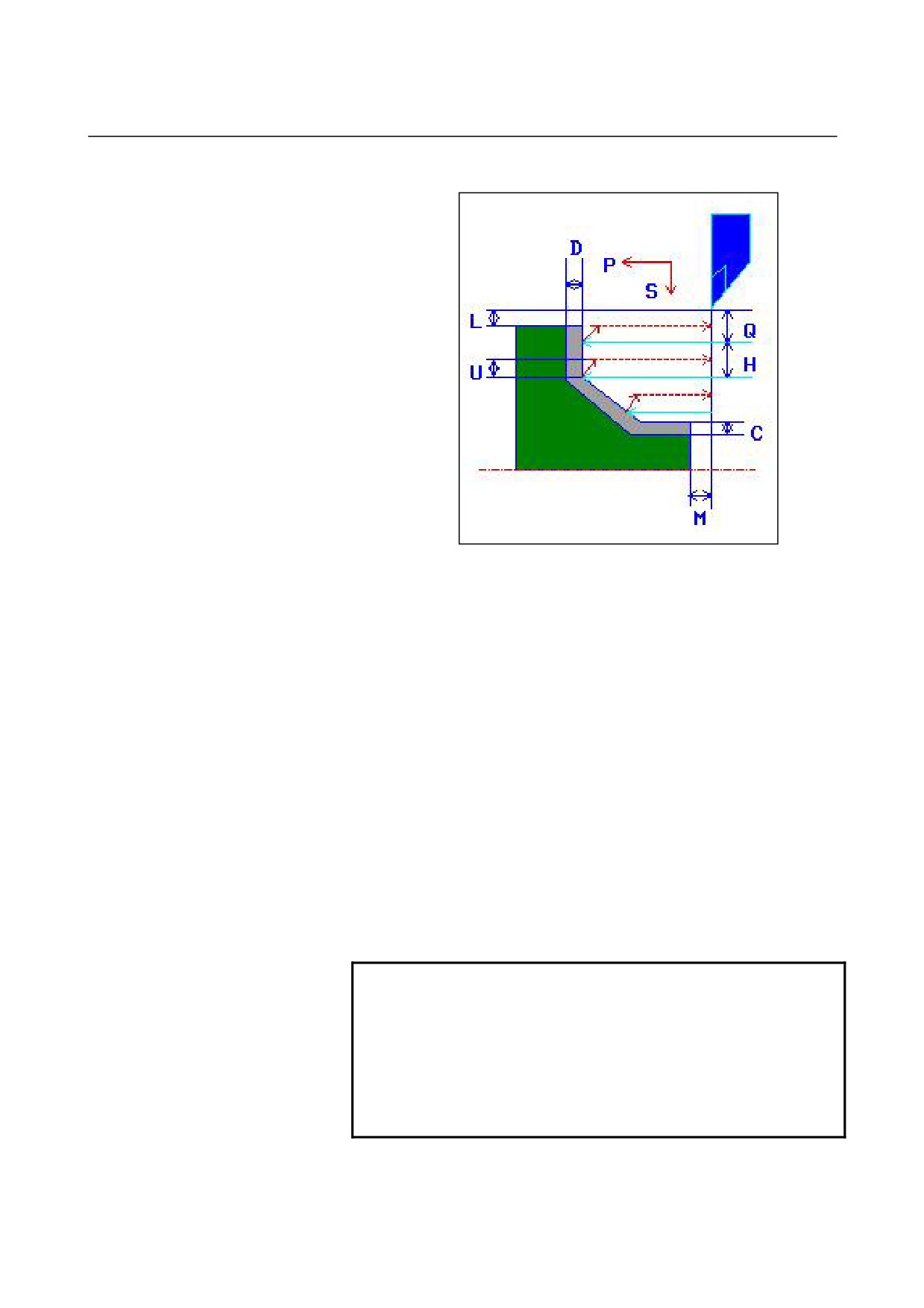
• Tool path
<1> The tool moves to the position "cut-in start point + clearance (L,
M)" by rapid traverse.
<2> After cutting in in the X-axis direction at the feedrate
(F)
specified for the cutting direction, the tool cuts in to the
entered-figure position where there is still a finishing allowance
in the Z-axis direction at the feedrate (E) specified for the cut-in
direction.
<3> If [SPEED] is selected, the tool immediately retracts by a return
clearance (U) in the X- and Z-axis direction. If [CUT] is selected,
the tool first cuts along the figure and then retracts by a return
clearance (U) in the X- and Z-axis direction.
<4> The tool moves to the cut-in start position in the Z-axis direction
by rapid traverse.
<5> Steps <2> to <4> are repeated until the lowest portion in the
X-axis direction is reached.
<6> If there is another pocket, the tool is positioned on the pocket,
and steps <2> to <4> are repeated.
<7> Once all portions are cut, the tool retracts to the position "cut-in
start position + clearance (L)" in the X-axis direction at the rapid
traverse rate.
NOTE
It is possible to specify "PART" and "BLANK" as
"ELEMENT TYPE" for an individual arbitrary figure.
This "BLANK" can be used to enter an arbitrary
figure resembling a blank figure to be actually
machined, so any portion other than the blank
portion will not be cut. This way, optimum rough
turning can be realized.
- 491 -