FANUC MANUAL GUIDE i. OPERATOR’S MANUAL - page 15
1.MILLING
CYCLE MACHINING TYPES
B-63874EN/05
DETAIL
Data item
Meaning
Z
APROCH MOTION
[2 AXES]
: When moving from the current
position to the machining start point,
the tool first moves in the machining
plane in two-axis synchronous
operation and then moves along the
tool axis. (initial value)
[3 AXES]
: The tool moves from the current
position to the machining start point in
three-axis synchronous operation.
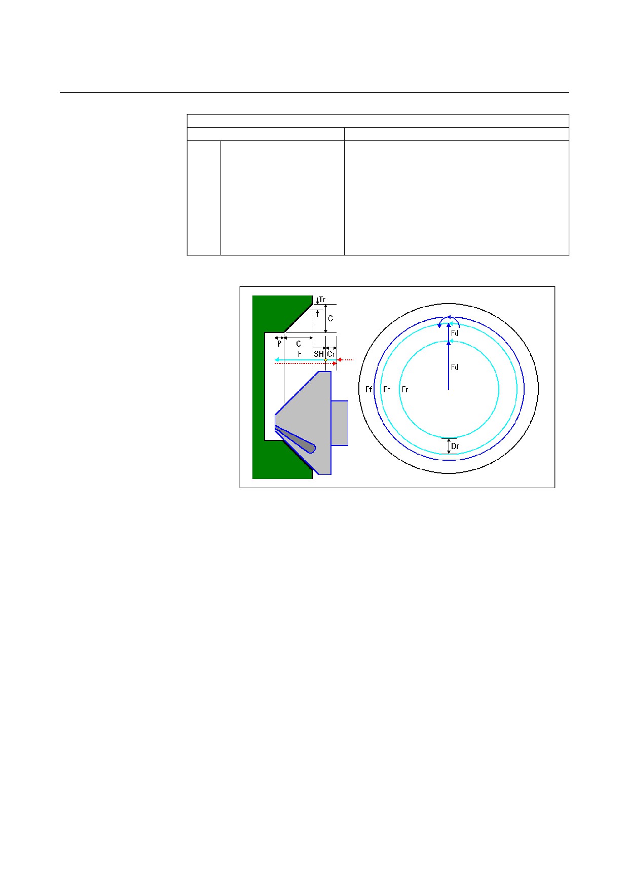
• Tool path
<1> The tool moves to the position "cutting start position + clearance
(Cr)" by rapid traverse.
<2> The tool moves to the position "amount to be chamfered (C) +
ejection stroke (P)" at the feedrate (F) specified for cutting.
<3> The tool cuts in to the portion to be chamfered by the cut depth
(Dr) in the tool radius direction at the feedrate (Fd) specified for
both-edge thread cutting.
<4> The tool cuts along the contour of the hole machining profile at
the feedrate (Fr) specified for single-edge thread cutting.
<5> Steps
<3> and
<4> are repeated until only the finishing
allowance (Tr) in the tool radius direction is left uncut.
<6> The tool turns around the finishing allowance (Tr) in the tool
radius direction to perform finishing at the feedrate (Ff) specified
for finishing.
<7> The tool moves to the position "cut-in start position + clearance
(Cr)" by rapid traverse.
- 402 -
B-63874EN/05
CYCLE MACHINING TYPES
1.MILLING
1.4.2
Fixed Form Figure Blocks for Contouring (XY Plane)
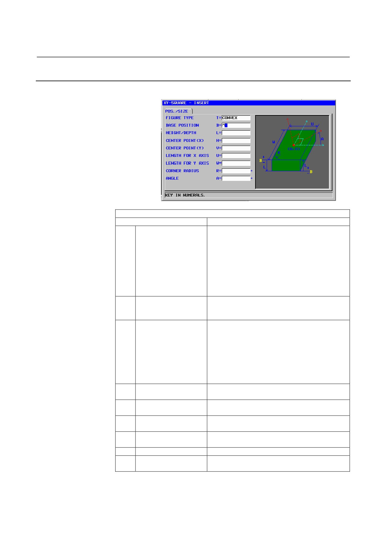
Square: G1220 (XY plane)
POS./SIZE
Data item
Meaning
T
FIGURE TYPE
[FACE]
: Used as a figure for facing
[CONVEX]
: Used as an outer figure for contouring
[CONCAVE] : Used as an inner figure for contouring
or as a figure for pocketing
[GROOVE] : Used as a figure for grooving
Remark) When contouring is selected as machining
type, select [CONVEX] if an outer figure is
to be machined; if an inner figure is to be
machined, select [CONCAVE].
B
BASE POSITION
Z coordinate of the top surface or the bottom of the
side face of a part to be subject to contouring (in the
tool axis direction)
L
HEIGHT/DEPTH
When the top surface of a workpiece is selected as
the BASE POSITION, specify the distance to the
bottom of the side face by using a negative value
(radius value). → Depth
When the bottom of a side face is selected as the
BASE POSITION, specify the distance to the top
surface of the workpiece by using a positive value
(radius value). → Height
H
CENTER POINT (X)
X coordinate of the center position of a rectangular
figure
V
CENTER POINT (Y)
Y coordinate of the center position of a rectangular
figure
U
LENGTH FOR X AXIS
Length of the side in the X-axis direction (radius
value, positive value)
W
LENGTH FOR Y AXIS
Length of the side in the Y-axis direction (radius
value, positive value)
R*
CORNER RADIUS
Radius for corner rounding (positive value)
A*
ANGLE
Inclination angle of a rectangular figure relative to
the X-axis (positive or negative value)
- 403 -
1.MILLING
CYCLE MACHINING TYPES
B-63874EN/05
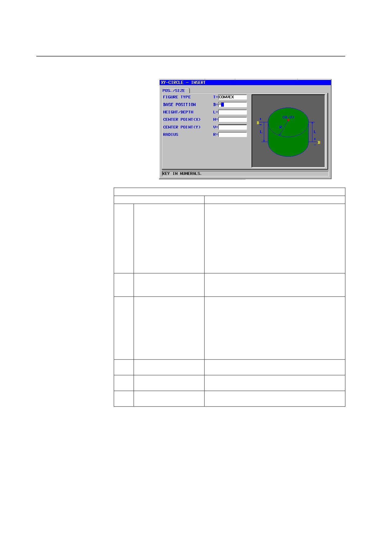
Circle: G1221 (XY plane)
POS./SIZE
Data item
Meaning
T
FIGURE TYPE
[FACE]
: Used as a figure for facing
[CONVEX]
: Used as an outer figure for contouring
[CONCAVE] : Used as an inner figure for contouring
or as a figure for pocketing
[GROOVE] : Used as a figure for grooving
Remark) When contouring is selected as machining
type, select [CONVEX] if an outer figure is
to be machined; if an inner figure is to be
machined, select [CONCAVE].
B
BASE POSITION
Z coordinate of the top surface or the bottom of the
side face of a part to be subject to contouring (in the
tool axis direction)
L
HEIGHT/DEPTH
When the top surface of a workpiece is selected as
the BASE POSITION, specify the distance to the
bottom of the side face by using a negative value
(radius value). → Depth
When the bottom of a side face is selected as the
BASE POSITION, specify the distance to the top
surface of the workpiece by using a positive value
(radius value). → Height
H
CENTER POINT (X)
X coordinate of the center position of a circular
figure
V
CENTER POINT (Y)
Y coordinate of the center position of a circular
figure
R
RADIUS
Radius of a circular figure (radius value, positive
value)
- 404 -
B-63874EN/05
CYCLE MACHINING TYPES
1.MILLING
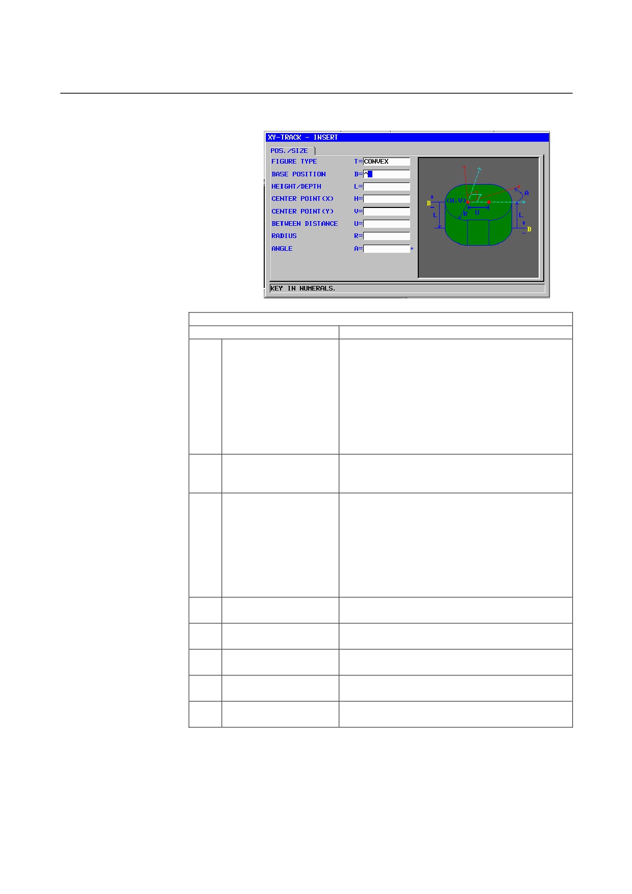
Track: G1222 (XY plane)
POS./SIZE
Data item
Meaning
T
FIGURE TYPE
[FACE]
: Used as a figure for facing
[CONVEX]
: Used as an outer figure for contouring
[CONCAVE] : Used as an inner figure for contouring
or as a figure for pocketing
[GROOVE] : Used as a figure for grooving
Remark) When contouring is selected as machining
type, select [CONVEX] if an outer figure is
to be machined; if an inner figure is to be
machined, select [CONCAVE].
B
BASE POSITION
Z coordinate of the top surface or the bottom of the
side face of a part to be subject to contouring(in the
tool axis direction)
L
HEIGHT/DEPTH
When the top surface of a workpiece is selected as
the BASE POSITION, specify the distance to the
bottom of the side face by using a negative value
(radius value). → Depth
When the bottom of a side face is selected as the
BASE POSITION, specify the distance to the top
surface of the workpiece by using a positive value
(radius value). → Height
H
CENTER POINT (X)
X coordinate of the center position of the left
semicircle
V
CENTER POINT (Y)
Y coordinate of the center position of the left
semicircle
U
BETWEEN DISTANCE
Distance between the centers of the right and left
semicircles (radius value, positive value)
R
RADIUS
Radius of the left and right semicircles (radius value,
positive value)
A*
ANGLE
Inclination angle of a track figure relative to the
X-axis (positive or negative value)
- 405 -
1.MILLING
CYCLE MACHINING TYPES
B-63874EN/05
1.4.3
Fixed Form Figure Blocks for Contouring (YZ Plane, XC
Plane)
The same fixed-figure block types as for the XY plane explained in
the previous subsection are available for the YZ plane and the XC
plane (polar coordinate interpolation plane). They are provided with
the following G codes.
The data to be set for the YZ and XC planes is the same as for the XY
plane except that the XY plane is changed to the YZ or XC plane and
that the direction in which the tool moves to cut is changed to the
X-axis (YZ plane) or the Z-axis (XC plane).
Square
: G1320 (YZ plane)
Square
: G1520 (XC plane), polar coordinate interpolation plane)
Circle
: G1321 (YZ plane)
Circle
: G1521 (XC plane), polar coordinate interpolation plane)
Track
: G1322 (YZ plane)
Track
: G1522 (XC plane), polar coordinate interpolation plane)
NOTE
When performing machining (polar coordinate
interpolation) on the XC plane, note the following:
(When bit 2 of parameter No. 27000 = 0)
The mode needs to be switched to the polar
coordinate interpolation mode beforehand.
Specifically, enter G12.1 before the machining
type.
Enter G13.1 for canceling polar coordinate
interpolation as required.
(When bit 2 of parameter No. 27000 = 1)
G12.1 and G13.1 are automatically output before
and after cycle machining, respectively.
- 406 -
B-63874EN/05
CYCLE MACHINING TYPES
1.MILLING
1.4.4
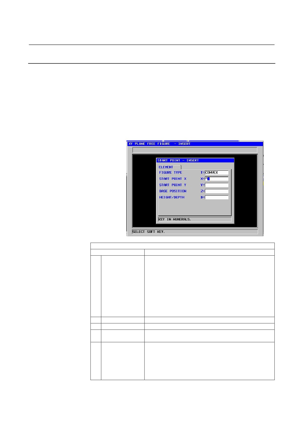
Arbitrary Figure Blocks for Contouring (XY Plane)
When an arbitrary figure for contouring is input, data such as a figure
type and machining reference position is specified in the start point block.
Other data items to be input such as a straight line and arc are exactly the
same as for arbitrary figures of other machining types.
So, this subsection describes only the start point block of an arbitrary
figure for contouring.
For other arbitrary figures, see Chapter
5, "DETAILED
DESCRIPTIONS ABOUT ENTERING ARBITRARY FIGURES," in
Part II.
Start point: G1200 (XY plane)
ELEMENT
Data item
Meaning
T
FIGURE TYPE
[FACE]
: Used as a figure for facing
[CONVEX]
: Used as an outer figure for contouring
[CONCAVE] : Used as an inner figure for contouring and
emboss machining or as a figure for pocketing
[GROOVE] : Used as a figure for grooving
[OPEN]
: Used when only one side is cut during
contouring
Remark) When contouring is specified as a machining type,
one of [CONVEX], [CONCAVE], and [OPEN] must
be selected.
X
START POINT X
X coordinate of the start point of an arbitrary figure
Y
START POINT Y
Y coordinate of the start point of an arbitrary figure
Z
BASE POSITION
Z coordinate of the top surface or the bottom of the side face
of a part to be subject to contouring (tool axis direction)
L
HEIGHT/DEPTH
When the top surface of a workpiece is selected as the BASE
POSITION, specify the distance to the bottom of the side
face by using a negative value (radius value). → Depth
When the bottom of a side face is selected as the BASE
POSITION, specify the distance to the top surface of the
workpiece by using a positive value (radius value). → Height
- 407 -

1.MILLING
CYCLE MACHINING TYPES
B-63874EN/05
ELEMENT
Data item
Meaning
P
FIGURE
[RIGHT] : The right side of an entered figure as viewed with
ATTRIBUTE
respect to the direction of movement is cut. (initial
value)
[LEFT]
: The left side of an entered figure as viewed with
respect to the direction of movement is cut. (initial
value)
Remark) These items are displayed only when [OPEN] is
selected as a figure type.
- 408 -
B-63874EN/05
CYCLE MACHINING TYPES
1.MILLING
1.4.5
Arbitrary Figure Blocks for Contouring (YZ Plane, XC Plane,
ZC Plane, XA Plane)
The same arbitrary-figure block types as for the XY plane explained
in the previous subsection are available for the YZ plane, the XC
plane (polar coordinate interpolation plane), ZC plane and XA plane
(cylindrical surface). Their start points are specified with the
following G codes.
The data to be set for the YZ, XC, ZC planes and XA plane is the
same as for the XY plane except that the XY plane is changed to the
YZ, XC, ZC XA plane and that the direction in which the tool moves
to cut is changed to the X-axis (YZ and ZC planes) or the Z-axis (XC
and XA plane).
Start point : G1300 (YZ plane)
Start point : G1500 (XC plane, polar coordinate interpolation plane)
Start point : G1600 (ZC plane, cylindrical surface)
Start point : G1700 (XA plane, cylindrical surface)
NOTE
1
When performing machining (polar coordinate
interpolation) on the XC plane, note the following:
(When bit 2 of parameter No. 27000 = 0)
The mode needs to be switched to the polar
coordinate interpolation mode beforehand.
Specifically, enter G12.1 before the machining
type.
Enter G13.1 for canceling polar coordinate
interpolation as required.
(When bit 2 of parameter No. 27000 = 1)
G12.1 and G13.1 are automatically output before
and after cycle machining, respectively.
2
When performing machining (cylindrical
interpolation) on the ZC and XA plane, note the
following:
(When bit 3 of parameter No. 27000 = 0)
The mode needs to be switched to the cylindrical
coordinate interpolation mode beforehand.
Specifically, enter G07.1C (cylinder radius) before
the machining type.
Enter G07.1C0 for canceling cylindrical
interpolation as required.
(When bit 3 of parameter No. 27000 = 1)
G07.1C (cylinder radius) and G07.1C0 are
automatically output before and after cycle
machining, respectively.
3
The following parameter setting is necessary to
execute XA plane cycle.
• No.27003#2=1, 27003#1=0 and 27003#0=0
- 409 -
1.MILLING
CYCLE MACHINING TYPES
B-63874EN/05
1.5
EMBOSS MACHINING
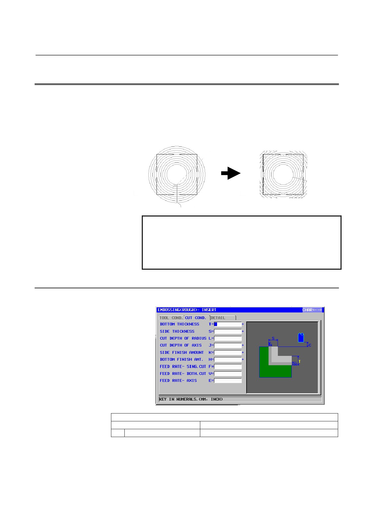
In the case of the contouring, the tool cuts along the side-face contour
of the machining profile and performs in-feed machining in the tool
radius direction. These tool passes sometimes generate many air-cut
movement as the following left figure.
So, the machining called “EMBOSS MACHINING CYCLE” that can
reduce the air-cut passes as the following right figure is prepared.
NOTE
1 This function is available when parameter
No.27000#7=1.
2 The parameters for the machining conditions for
embossing cycles are same with the parameters for
pocketing cycles. (Ex. No. 27066)
1.5.1
Machining Type Blocks for Emboss machining
Rough: G1080
TOOL COND.
Data item
Meaning
D
TOOL DIAMETER
End mill diameter
- 410 -
B-63874EN/05
CYCLE MACHINING TYPES
1.MILLING
NOTE
1 Tab ‘TOOL COND.’ is enabled when bit 0 (TLG) of
parameter No. 27002 = 1.
2 The operator ordinarily sets the above data on the
tab of ‘TOOL DATA’ in Tool Offset window.
Therefore, it is not necessary to display the tab
‘TOOL COND.’
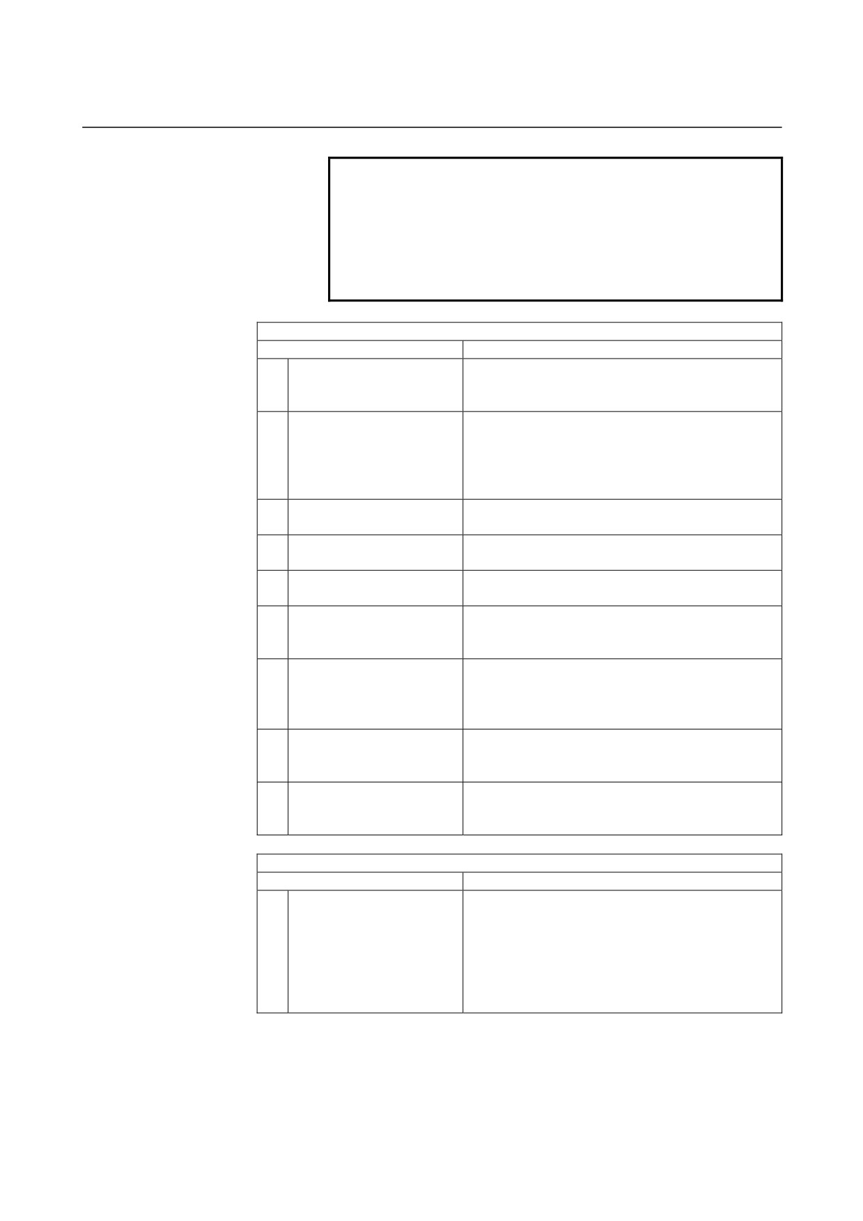
CUT COND.
Data item
Meaning
T*
BOTTOM THICKNESS
Cutting allowance of the bottom in side face
machining. The blank is regarded as 0. (radius
value, positive value)
S*
SIDE THICKNESS
Cutting allowance of the side face. The blank is
regarded as 0. (radius value, positive value)
Remark) When both the side surplus thickness and
bottom surplus thickness are omitted, an
entire pocket area is cut.
L
CUT DEPTH OF RADIUS
Depth of cut on the side face (tool radius direction)
per cutting operation (radius value, positive value)
J
CUT DEPTH OF AXIS
Depth of cut in the tool axis direction per cutting
operation (radius value, positive value)
K*
SIDE FINISH AMOUNT
Finishing allowance on the side face. The blank is
regarded as 0. (radius value, positive value)
H*
BOTTOM FINISHI AMT.
Finishing allowance at the bottom in side face
machining. The blank is regarded as 0. (radius
value, positive value)
F
FEED RATE- SING.CUT
Feedrate applicable when only the one-side cutter
portion of an end mill is used for cutting. This
feedrate is used for cutting in retract operation and
on the side face other than initial cutting.
V
FEED RATE- BOTH.CUT
Feedrate applicable when the entire front side of an
end mill is used for cutting. This feedrate is used for
initial cutting.
E
FEED RATE- AXIS
Feedrate applicable when cutting is performed in the
tool axis direction toward the bottom of a side face
being machined
DETAIL
Data item
Meaning
W
UP CUT/DOWN CUT
[UP CUT]
: Performs machining in up-cut mode,
assuming that the tool is rotating
clockwise.
[DWNCUT] : Performs machining in down-cut
mode, assuming that the tool is
rotating clockwise.
(COPY)
- 411 -

1.MILLING
CYCLE MACHINING TYPES
B-63874EN/05
DETAIL
Data item
Meaning
B
CLEARANCE OF RADIUS
Distance between the side face and a tool retract
position in the tool radius direction (radius value,
positive value)
Remark1) When one pocket cutting operation is
completed, the tool performs a retract
operation in the tool axis direction from
the side face of the pocket by this
clearance amount.
Remark2) By referring to the parameter No.27009
(minimum clamp value), the system sets
the data as Initial value.
C
CLEARANCE OF AXIS
Distance between the surface of a blank being
machined and a cutting start point (point R) in the
tool axis direction (radius value, positive value)
Remark) By referring to the parameter No.27009
(minimum clamp value), the system sets
the data as Initial value.
Z
APROCH MOTION
[2 AXES]
: When moving from the current position
to the machining start point, the tool first
moves in the machining plane in
two-axis synchronous operation and
then moves along the tool axis. (initial
value)
[3 AXES]
: The tool moves from the current
position to the machining start point in
three-axis synchronous operation.
- 412 -

B-63874EN/05
CYCLE MACHINING TYPES
1.MILLING
Bottom Finish: G1081
TOOL COND.
Data item
Meaning
D
TOOL DIAMETER
End mill diameter
NOTE
1 Tab ‘TOOL COND.’ is enabled when bit 0 (TLG) of
parameter No. 27002 = 1.
2 The operator ordinarily sets the above data on the
tab of ‘TOOL DATA’ in Tool Offset window.
Therefore, it is not necessary to display the tab
‘TOOL COND.’
CUT COND.
Data item
Meaning
T*
BOTTOM THICKNESS
Cutting allowance at the bottom in side face
machining. The blank is regarded as 0. (radius
value, positive value)
K*
SIDE FINISH AMOUNT
Finishing allowance of the side face. The blank is
regarded as 0. (radius value, positive value)
H*
BOTTOM FINISHI AMT.
Finishing allowance at the bottom in side face
machining. The blank is regarded as 0. (radius
value, positive value)
L
CUT DEPTH OF RADIUS
Depth of cut on the side face (tool radius direction)
per cutting operation (radius value, positive value)
F
FEED RATE- SING.CUT
Feedrate applicable when only the one-side cutter
portion of an end mill is used for cutting. This
feedrate is used for cutting in retract operation and
on the side face other than initial cutting.
V
FEED RATE- BOTH.CUT
Feedrate applicable when the entire front side of an
end mill is used for cutting. This feedrate is used for
initial cutting.
E
FEED RATE- AXIS
Feedrate applicable when cutting is performed in the
tool axis direction toward the bottom of a side face
being machined
- 413 -

1.MILLING
CYCLE MACHINING TYPES
B-63874EN/05
DETAIL
Data item
Meaning
W
UP CUT/DOWN CUT
[UP CUT]
: Performs machining in up-cut mode,
assuming that the tool is rotating
clockwise.
[DWNCUT] : Performs machining in down-cut
mode, assuming that the tool is
rotating clockwise.
(COPY)
B
CLEARANCE OF RADIUS
Distance between the side face and a tool retract
position in the tool radius direction (radius value,
positive value)
Remark1) When one pocket cutting operation is
completed, the tool performs a retract
operation in the tool axis direction from
the side face of the pocket by this
clearance amount.
Remark2) By referring to the parameter No.27009
(minimum clamp value), the system sets
the data as Initial value.
C
CLEARANCE OF AXIS
Distance between the surface of a blank being
machined and a cutting start point (point R) in the
tool axis direction (radius value, positive value)
Remark) By referring to the parameter No.27009
(minimum clamp value), the system sets
the data as Initial value.
Z
APROCH MOTION
[2 AXES]
: When moving from the current position
to the machining start point, the tool first
moves in the machining plane in
two-axis synchronous operation and
then moves along the tool axis. (initial
value)
[3 AXES]
: The tool moves from the current
position to the machining start point in
three-axis synchronous operation.
- 414 -
B-63874EN/05
CYCLE MACHINING TYPES
1.MILLING
Side face finish: G1082
TOOL COND.
Data item
Meaning
I
INPUT
[INPUT] : Inputs a cutter compensation value directly.
[REF.]
: Inputs a cutter compensation number to
read a cutter compensation value by that
number.
D
TOOL DIAMETER
End mill diameter (positive value)
Remark) This item is indicated only when [INPUT] is
selected for INPUT.
M
CUTTER COMP.NO.
Cutter compensation number of an end mill (positive
value)
Remark) This item is indicated only when [REF.] is
selected for INPUT.
NOTE
1 Tab ‘TOOL COND.’ is enabled when bit 0 (TLG) of
parameter No. 27002 = 1.
2 The operator ordinarily sets the above data on the
tab of ‘TOOL DATA’ in Tool Offset window.
Therefore, it is not necessary to display the tab
‘TOOL COND.’
3 Tab ‘TOOL COND.’ is not enabled when bit 3 (PF3)
of parameter No. 27061 = 1.
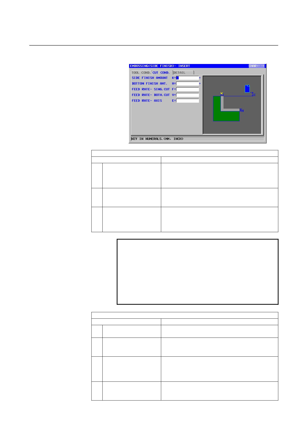
CUT COND.
Data item
Meaning
K*
SIDE FINISH AMOUNT
Finishing allowance of the side face. The blank is
regarded as 0. (radius value, positive value)
H*
BOTTOM FINISHI AMT.
Finishing allowance at the bottom in side face
machining. The blank is regarded as 0. (radius
value, positive value)
F
FEED RATE- SING.CUT
Feedrate applicable when only the one-side cutter
portion of an end mill is used for cutting. This feedrate
is used for cutting in retract operation and on the side
face other than initial cutting.
V
FEED RATE- BOTH.CUT
Feedrate applicable when the entire front side of an
end mill is used for cutting. This feedrate is used for
initial cutting.
- 415 -
1.MILLING
CYCLE MACHINING TYPES
B-63874EN/05
CUT COND.
Data item
Meaning
E
FEED RATE- AXIS
Feedrate applicable when cutting is performed in the
tool axis direction toward the bottom of a side face
being machined
DETAIL
Data item
Meaning
W
UP CUT/DOWN CUT
[UP CUT]
: Performs machining in up-cut mode,
assuming that the tool is rotating
clockwise.
[DWNCUT] : Performs machining in down-cut mode,
assuming that the tool is rotating
clockwise.
(COPY)
C
CLEARANCE OF AXIS
Distance between the surface of a blank being
machined and a cutting start point (point R) in the tool
axis direction (radius value, positive value)
Remark) By referring to the parameter No.27009
(minimum clamp value), the system sets the
data as Initial value.
P
APPROACH TYPE
[ARC]
: Approaches a side face along an arc.
[TANGEN]: Approaches a side face along the straight
line tangent to the first figure in side face
cutting.
[VERTIC] : Approaches a side face along the straight
line normal to the first figure in side face
cutting.
(COPY)
R
APPROACH RAD./DIST.
Radius when [ARC] is specified.
Straight line length when [TANGEN] or [VERTIC] is
specified. (radius value, positive value)
Remark) By referring to the parameter No.27010
(minimum clamp value), the system sets the
data as Initial value.
A*
APPROACH ANGLE
Center angle of the arc when [ARC] is specified. The
default is 90 degrees. (positive value)
Remark) This data item is indicated only when [ARC]
is selected for APPROACH TYPE.
(COPY)
Q
ESCAPE TYPE
[ARC]
: Retracts from a side face along an arc.
[TANGEN]: Retracts from a side face along the
straight line tangent to the last figure in
side face cutting.
[VERTIC] : Retracts from a side face along the
straight line normal to the last figure in
side face cutting.
(COPY)
- 416 -

B-63874EN/05
CYCLE MACHINING TYPES
1.MILLING
DETAIL
Data item
Meaning
X
ESCAPE RAD./DIST.
Radius when [ARC] is specified.
Straight line length when [TANGEN] or [VERTIC] is
specified. (radius value, positive value)
Remark) By referring to the parameter No.27010
(minimum clamp value), the system sets the
data as Initial value.
Y*
ESCAPE ANGLE
Center angle of the arc when [ARC] is specified. The
default is 90 degrees. (positive value)
Remark) This data item is indicated only when [ARC]
is selected for ESCAPE TYPE.
(COPY)
Z
APROCH MOTION
[2 AXES]
: When moving from the current position to
the machining start point, the tool first
moves in the machining plane in two-axis
synchronous operation and then moves
along the tool axis. (initial value)
[3 AXES]
: The tool moves from the current position
to the machining start point in three-axis
synchronous operation.
- 417 -
1.MILLING
CYCLE MACHINING TYPES
B-63874EN/05
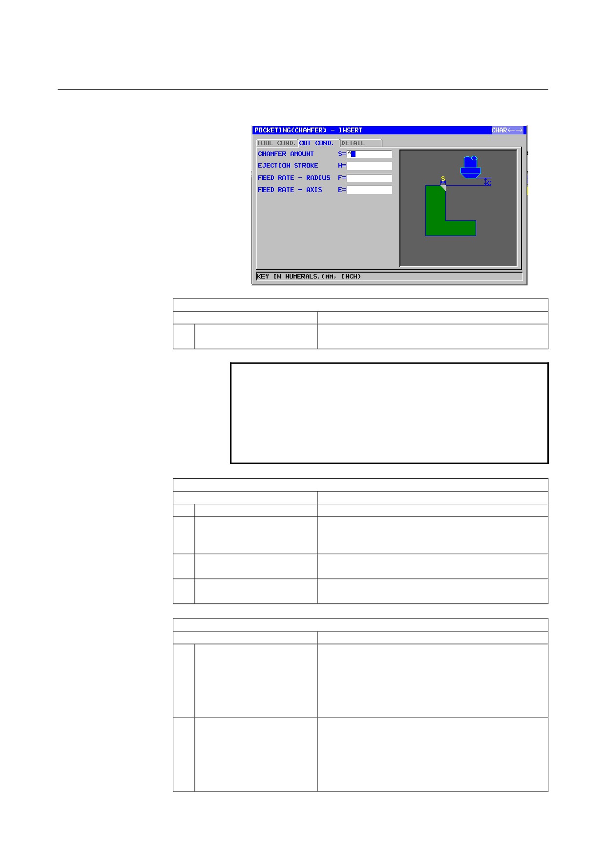
Chamfer: G1083
TOOL COND.
Data item
Meaning
K
TOOL SMALL DIAMETER
Diameter of the tip of a chamfering tool (positive
value)
NOTE
1 Tab ‘TOOL COND.’ is enabled when bit 0 (TLG) of
parameter No. 27002 = 1.
2 The operator ordinarily sets the above data on the
tab of ‘TOOL DATA’ in Tool Offset window.
Therefore, it is not necessary to display the tab
‘TOOL COND.’
CUT COND.
Data item
Meaning
S
CHAMFER AMOUNT
Chamfer length (radius value, positive value)
H
EJECTION STROKE
Distance between the tip of a chamfering tool and an
actually cut position in the tool axis direction (radius
value, positive value)
F
FEED RATE - RADIUS
Feedrate applicable when cutting is performed in the
tool radius direction
E
FEED RATE - AXIS
Feedrate applicable when cutting is performed in the
tool axis direction
DETAIL
Data item
Meaning
W
UP CUT/DOWN CUT
[UP CUT]
: Performs machining in up-cut mode,
assuming that the tool is rotating
clockwise.
[DWNCUT] : Performs machining in down-cut mode,
assuming that the tool is rotating
clockwise. (initial value)
C
CLEARANCE OF AXIS
Distance between the surface of a blank being
machined and a cutting start point (point R) in the tool
axis direction (radius value, positive value)
Remark) By referring to the parameter No.27009
(minimum clamp value), the system sets the
data as Initial value.
- 418 -

B-63874EN/05
CYCLE MACHINING TYPES
1.MILLING
DETAIL
Data item
Meaning
P
APPROACH TYPE
[ARC]
: Approaches a side face along an arc.
[TANGEN]: Approaches a side face along the straight
line tangent to the first figure in side face
cutting.
[VERTIC] : Approaches a side face along the straight
line normal to the first figure in side face
cutting.
(COPY)
R
APPROACH RAD./DIST.
Radius when [ARC] is specified.
Straight line length when [TANGEN] or [VERTIC] is
specified. (radius value, positive value)
Remark) By referring to the parameter No.27010
(minimum clamp value), the system sets the
data as Initial value.
A*
APPROACH ANGLE
Center angle of the arc when [ARC] is specified. The
default is 90 degrees. (positive value)
Remark) This data item is indicated only when [ARC]
is selected for APPROACH TYPE.
(COPY)
Q
ESCAPE TYPE
[ARC]
: Retracts from a side face along an arc.
[TANGEN]: Retracts from a side face along the
straight line tangent to the last figure in
side face cutting.
[VERTIC] : Retracts from a side face along the
straight line normal to the last figure in
side face cutting.
(COPY)
X
ESCAPE RAD./DIST.
Radius when [ARC] is specified.
Straight line length when [TANGEN] or [VERTIC] is
specified. (radius value, positive value)
Remark) By referring to the parameter No.27010
(minimum clamp value), the system sets the
data as Initial value.
Y*
ESCAPE ANGLE
Center angle of the arc when [ARC] is specified. The
default is 90 degrees. (positive value)
Remark) This data item is indicated only when [ARC]
is selected for ESCAPE TYPE.
(COPY)
Z
APROCH MOTION
[2 AXES]
: When moving from the current position to
the machining start point, the tool first
moves in the machining plane in two-axis
synchronous operation and then moves
along the tool axis. (initial value)
[3 AXES]
: The tool moves from the current position
to the machining start point in three-axis
synchronous operation.
- 419 -
1.MILLING
CYCLE MACHINING TYPES
B-63874EN/05
1.5.2
Arbitrary Figure Blocks for Emboss machining (XY Plane)
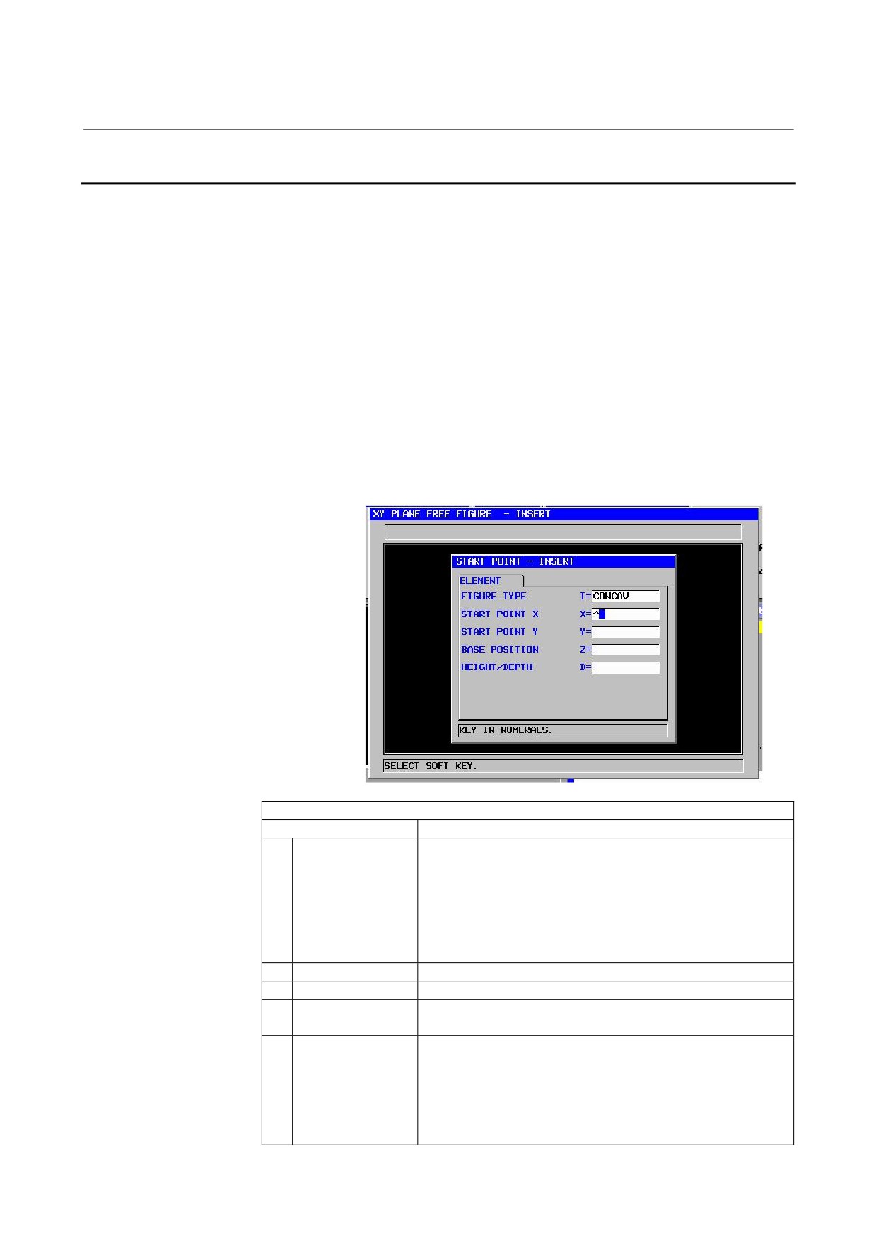
When an arbitrary figure for emboss machining is input, data such as a
figure type and machining reference position is specified in the start
point block. Other data items to be input such as a straight line and arc
are exactly the same as for arbitrary figures of other machining types.
So, this subsection describes only the start point block of an arbitrary
figure for pocketing.
For other arbitrary figures, see Chapter
5, "DETAILED
DESCRIPTIONS ABOUT ENTERING ARBITRARY FIGURES," in
Part II.
In creating the arbitrary figure for the emboss machining, create the
arbitrary figures which are the outside boundary of the cutting area at
fast. After finishing the outside boundary figures, press [ISLAND]
soft key and create the arbitrary figures which are the contour product
figure.
Start point: G1200 (XY plane)
ELEMENT
Data item
Meaning
T
FIGURE TYPE
[FACE]
: Used as a figure for facing
[CONVEX]
: Used as an outer figure for contouring
[CONCAVE] : Used as an inner figure for contouring and
emboss machining or as a figure for pocketing
[GROOVE] : Used as a figure for grooving
Remark) When emboss machining is selected as machining
type, be sure to select [CONCAVE].
X
START POINT X
X coordinate of the start point of an arbitrary figure
Y
START POINT Y
Y coordinate of the start point of an arbitrary figure
B
BASE POSITION
Z coordinate of the top surface of a workpiece subject to
pocketing or the bottom of a pocket (in the tool axis direction)
L
HEIGHT/DEPTH
When the top surface of a workpiece is selected as the BASE
POSITION, specify the distance to the bottom of the side
face by using a negative value (radius value). → Depth
When the bottom of the side face is selected as the BASE
POSITION, specify the distance to the top surface of the
pocket by using a positive value (radius value). → Height
- 420 -
B-63874EN/05
CYCLE MACHINING TYPES
1.MILLING
1.5.3
Arbitrary Figure Blocks for Emboss machining (YZ Plane, XC
Plane, ZC Plane, XA plane)
The same arbitrary-figure block types as for the XY plane explained
in the previous subsection are available for the YZ plane, the XC
plane (polar coordinate interpolation plane), ZC plane and XA plane
(cylindrical surface). Their start points are specified with the
following G codes.
The data to be set for the YZ, XC, ZC and XA planes is the same as
for the XY plane except that the XY plane is changed to the YZ, XC,
ZC or XA plane and that the direction in which the tool moves to cut
is changed to the X-axis (YZ and ZC planes) or the Z-axis (XC and
XA plane).
Start point : G1300 (YZ plane)
Start point : G1500 (XC plane, polar coordinate interpolation plane)
Start point : G1600 (ZC plane, cylindrical surface)
Start point : G1700 (XA plane, cylindrical surface)
NOTE
1
When performing machining (polar coordinate
interpolation) on the XC plane, note the following:
(When bit 2 of parameter No. 27000 = 0)
The mode needs to be switched to the polar
coordinate interpolation mode beforehand.
Specifically, enter G12.1 before the machining
type.
Enter G13.1 for canceling polar coordinate
interpolation as required.
(When bit 2 of parameter No. 27000 = 1)
G12.1 and G13.1 are automatically output before
and after cycle machining, respectively.
2
When performing machining (cylindrical
interpolation) on the ZC and XA plane, note the
following:
(When bit 3 of parameter No. 27000 = 0)
The mode needs to be switched to the cylindrical
coordinate interpolation mode beforehand.
Specifically, enter G07.1C (cylinder radius) before
the machining type.
Enter G07.1C0 for canceling cylindrical
interpolation as required.
(When bit 3 of parameter No. 27000 = 1)
G07.1C (cylinder radius) and G07.1C0 are
automatically output before and after cycle
machining, respectively.
3
The following parameter setting is necessary to
execute XA plane cycle.
No.27003#2=1, 27003#1=0 and 27003#0=0
- 421 -
1.MILLING
CYCLE MACHINING TYPES
B-63874EN/05
1.6
POCKETING
1.6.1
Machining Type Blocks for Pocketing
Rough: G1040
TOOL COND.
Data item
Meaning
D
TOOL DIAMETER
End mill diameter
NOTE
1 Tab ‘TOOL COND.’ is enabled when bit 0 (TLG) of
parameter No. 27002 = 1.
2 The operator ordinarily sets the above data on the
tab of ‘TOOL DATA’ in Tool Offset window.
Therefore, it is not necessary to display the tab
‘TOOL COND.’
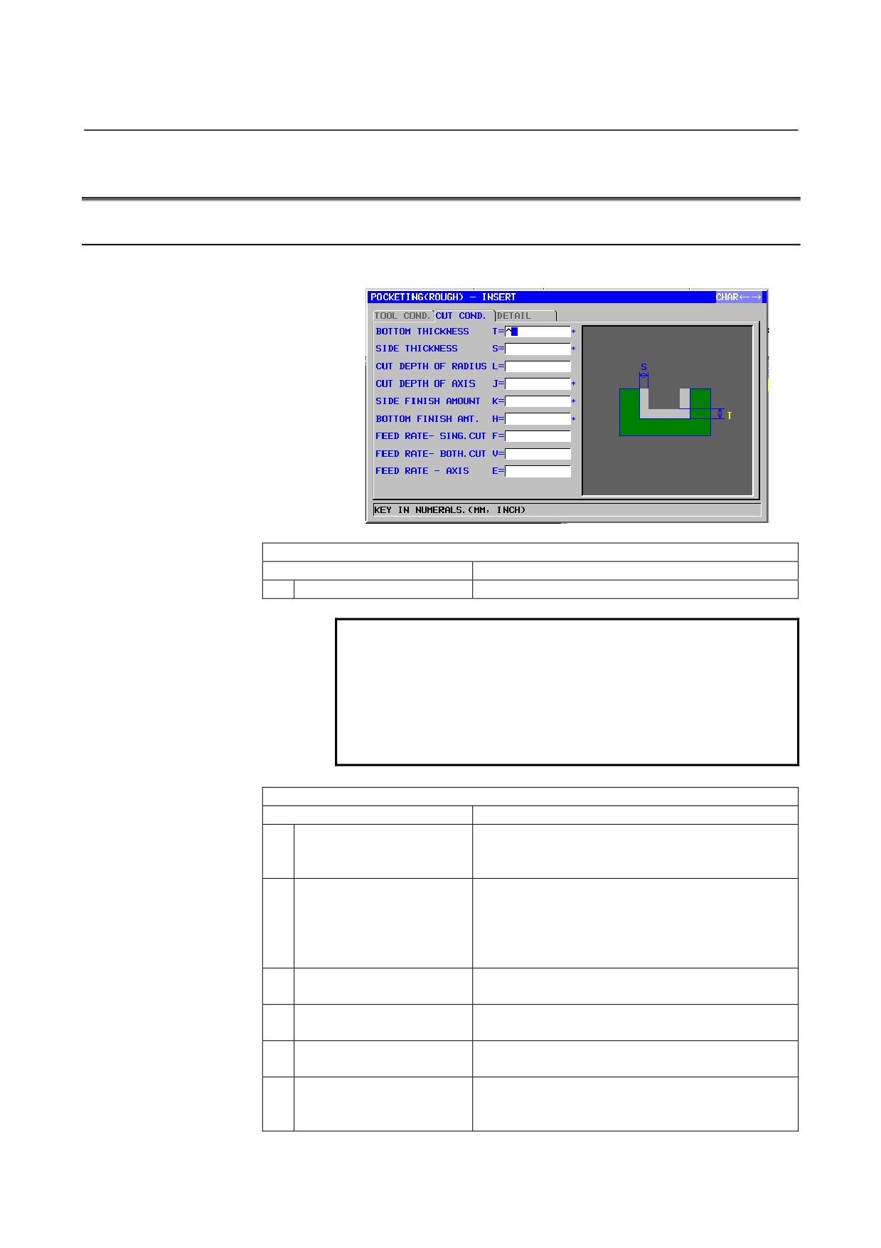
CUT COND.
Data item
Meaning
T*
BOTTOM THICKNESS
Cutting allowance of the bottom in side face
machining. The blank is regarded as 0. (radius
value, positive value)
S*
SIDE THICKNESS
Cutting allowance of the side face. The blank is
regarded as 0. (radius value, positive value)
Remark) When both the side surplus thickness and
bottom surplus thickness are omitted, an
entire pocket area is cut.
L
CUT DEPTH OF RADIUS
Depth of cut on the side face (tool radius direction)
per cutting operation (radius value, positive value)
J
CUT DEPTH OF AXIS
Depth of cut in the tool axis direction per cutting
operation (radius value, positive value)
K*
SIDE FINISH AMOUNT
Finishing allowance on the side face. The blank is
regarded as 0. (radius value, positive value)
H*
BOTTOM FINISHI AMT.
Finishing allowance at the bottom in side face
machining. The blank is regarded as 0. (radius
value, positive value)
- 422 -
B-63874EN/05
CYCLE MACHINING TYPES
1.MILLING
CUT COND.
Data item
Meaning
F
FEED RATE- SING.CUT
Feedrate applicable when only the one-side cutter
portion of an end mill is used for cutting. This
feedrate is used for cutting in retract operation and
on the side face other than initial cutting.
V
FEED RATE- BOTH.CUT
Feedrate applicable when the entire front side of an
end mill is used for cutting. This feedrate is used for
initial cutting.
E
FEED RATE- AXIS
Feedrate applicable when cutting is performed in the
tool axis direction toward the bottom of a side face
being machined
NOTE
When a non-zero value is input for just one of the
data items, side surplus thickness and bottom
surplus thickness, cutting is performed for the input
surplus thickness, and for the omitted surplus
thickness, cutting operation is not performed on the
assumption that the omitted surplus thickness is 0.
When non-zero values are input for both the side
surplus thickness and bottom surplus thickness,
cutting is performed for each surplus thickness.
DETAIL
Data item
Meaning
W
UP CUT/DOWN CUT
[UP CUT]
: Performs machining in up-cut mode,
assuming that the tool is rotating
clockwise.
[DWNCUT] : Performs machining in down-cut
mode, assuming that the tool is
rotating clockwise.
(COPY)
B
CLEARANCE OF RADIUS
Distance between the wall of a pocket and a tool
retract position in the tool radius direction (radius
value, positive value)
Remark1) When one pocket cutting operation is
completed, the tool performs a retract
operation in the tool axis direction from
the side face of the pocket by this
clearance amount.
Remark2) By referring to the parameter No.27009
(minimum clamp value), the system sets
the data as Initial value.
C
CLEARANCE OF AXIS
Distance between the surface of a blank being
machined and a cutting start point (point R) in the
tool axis direction (radius value, positive value)
Remark) By referring to the parameter No.27009
(minimum clamp value), the system sets
the data as Initial value.
- 423 -

1.MILLING
CYCLE MACHINING TYPES
B-63874EN/05
DETAIL
Data item
Meaning
Z
APROCH MOTION
[2 AXES]
: When moving from the current position
to the machining start point, the tool first
moves in the machining plane in
two-axis synchronous operation and
then moves along the tool axis. (initial
value)
[3 AXES]
: The tool moves from the current
position to the machining start point in
three-axis synchronous operation.
A*
CUT ANGLE
Angle at which the tool cuts into the pocket
obliquely. The blank is regarded as 0 degrees. (in
one-degree increments, positive value)
Remark) By performing cutting also using the side
face of an end mill, the load on the tool can
be reduced.
(COPY)
P*
START PT.(1ST AXIS)
1st-axis coordinate of the cutting start point of
pocketing. When omitting this item, also omit the
2nd-axis coordinate. In this case, the coordinates of
the start point are determined automatically.
Remark1) The 1st axis is the X-axis on the XY
plane, the Y-axis on the YZ plane, the
X-axis on the XC plane, the Z-axis on the
ZC plane, or the X-axis on the XA plane.
Remark2) This item is enable when the parameter
No. 27060#7(PR7) = 1.
Q*
START PT.(2ND AXIS)
2nd-axis coordinate of the cutting start point of
pocketing. When this item is omitted, the coordinate
is determined automatically.
Remark1) The 2nd axis is the Y-axis on the XY
plane, the Z-axis on the YZ plane, the
C-axis on the XC plane, the C-axis on the
ZC plane, or the A-axis on the XA plane.
Remark2) This item is enable when the parameter
No. 27060#7(PR7) = 1.
- 424 -
B-63874EN/05
CYCLE MACHINING TYPES
1.MILLING
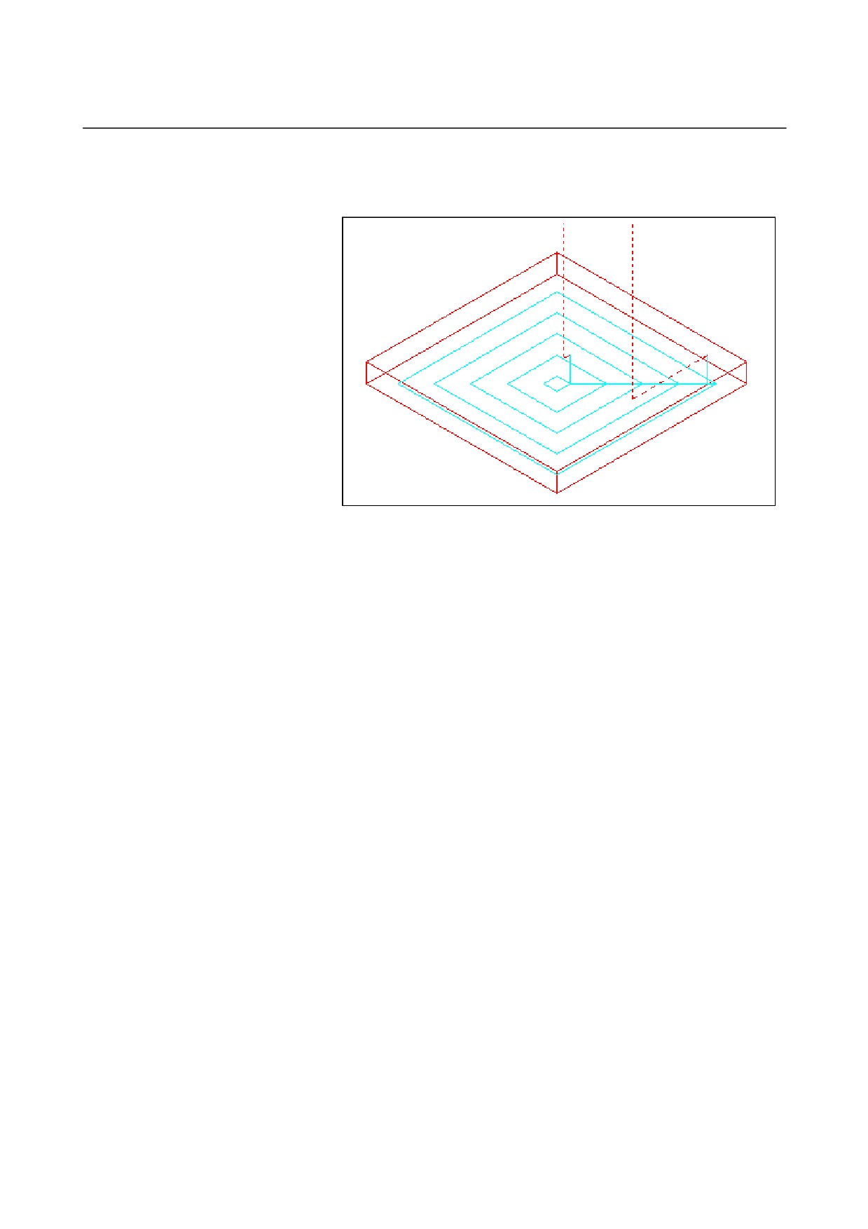
• Tool path
The inside of a pocket machining profile is cut off in a spiral manner.
The following tool path is created.
More than one island machining profile and more than one cavity
machining profile can be defined for a pocket machining profile. The
island machining profiles are left uncut.
The cavity machining profiles are detoured so that they will not be
cut.
The tool path is created in such a way that an anticipated interference
with pocket machining profiles or island machining profiles can be
avoided.
The created tool path is effective because retraction in the tool axis
direction is avoided as much as possible.
For this tool path, in-feed machining in the tool axis direction is
possible.
Only specified cutting allowances can be cut off.
The direction of cutting can be either up-cut or down-cut. The
direction of cutting is controlled automatically around islands.
It is possible to cut in from the inside and outside of the machining
profile.
If there is a portion left uncut at a corner, it is possible to
automatically discriminate the uncut portion and cut it off.
It is possible to cut in at an arbitrary angle in the tool axis direction.
It is possible to specify an arbitrary position as a cutting start point.
It is possible to determine a cutting start point automatically.
It is possible to select a movement method for tool movement.
It is possible to control automatically a cut-in depth on the island
machining profile top surface automatically.
It is possible to set up cutting conditions, such as finishing allowance
for island machining profiles, for each island machining profile.
- 425 -
1.MILLING
CYCLE MACHINING TYPES
B-63874EN/05
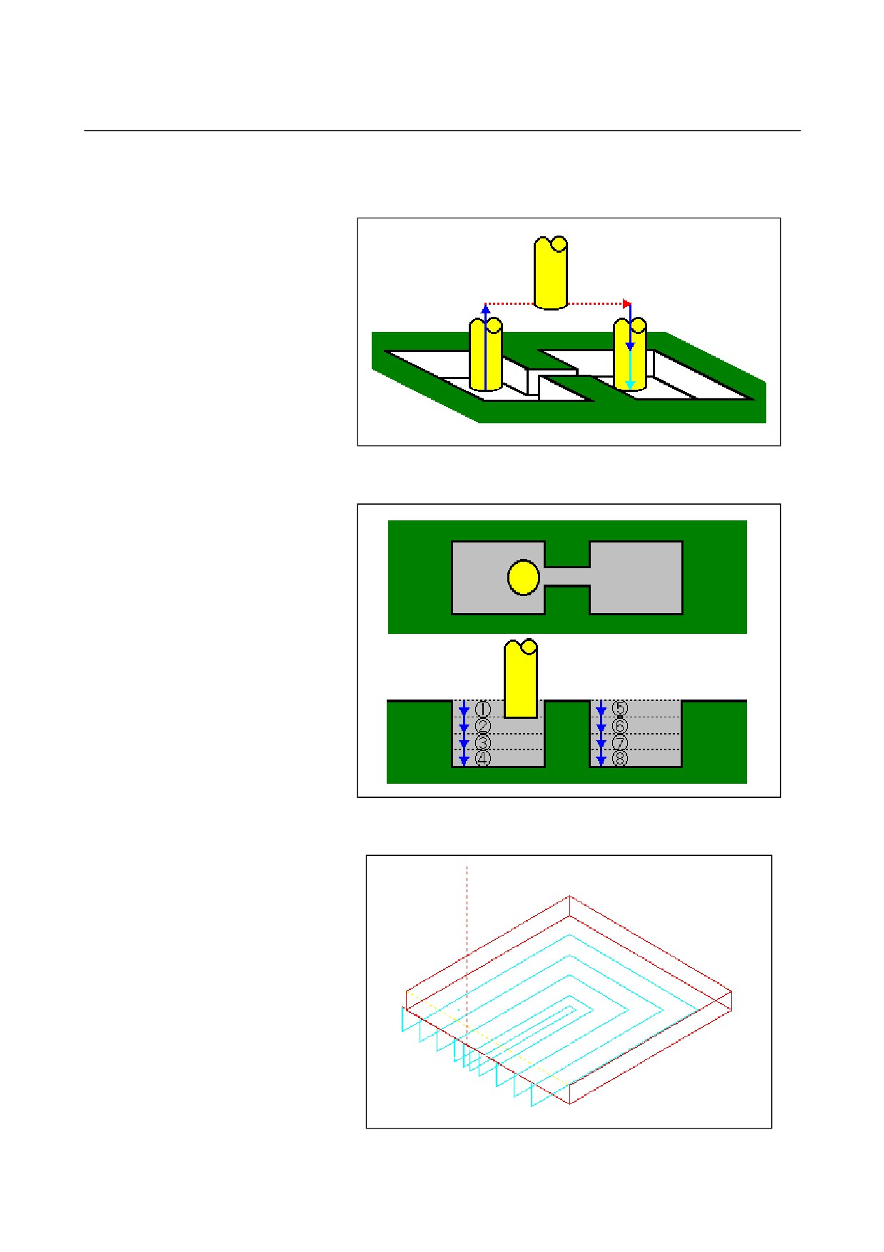
In the following pocket machining profile, which has a pocket through
which the tool can pass, the tool is lifted automatically to cut only a
range that can be cut.
If there is more than one cut in the tool axis direction, each range is
cut completely before another.
A contour specified as an open element of a pocket machining profile
is cut off as shown below.
- 426 -
B-63874EN/05
CYCLE MACHINING TYPES
1.MILLING
Bottom Finish: G1041
TOOL COND.
Data item
Meaning
D
TOOL DIAMETER
End mill diameter
NOTE
1 Tab ‘TOOL COND.’ is enabled when bit 0 (TLG) of
parameter No. 27002 = 1.
2 The operator ordinarily sets the above data on the
tab of ‘TOOL DATA’ in Tool Offset window.
Therefore, it is not necessary to display the tab
‘TOOL COND.’
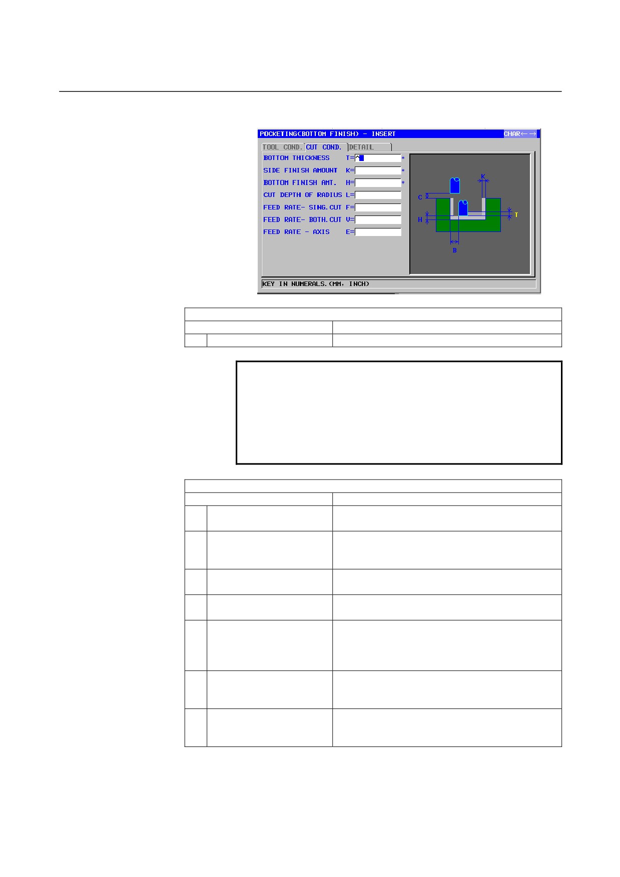
CUT COND.
Data item
Meaning
T*
BOTTOM THICKNESS
Cutting allowance at the bottom of a pocket. The
blank is regarded as 0. (radius value, positive value)
K*
SIDE FINISH AMOUNT
Finishing allowance on the side face of a pocket.
The blank is regarded as 0. (radius value, positive
value)
H*
BOTTOM FINISHI AMT.
Finishing allowance at the bottom of a pocket. The
blank is regarded as 0. (radius value, positive value)
L
CUT DEPTH OF RADIUS
Depth of cut on the side face (tool radius direction)
per cutting operation (radius value, positive value)
F
FEED RATE- SING.CUT
Feedrate applicable when only the one-side cutter
portion of an end mill is used for cutting. This
feedrate is used for cutting in retract operation and
on the side face other than initial cutting.
V
FEED RATE- BOTH.CUT
Feedrate applicable when the entire front side of an
end mill is used for cutting. This feedrate is used for
initial cutting.
E
FEED RATE- AXIS
Feedrate applicable when cutting is performed in the
tool axis direction toward the bottom of a side face
being machined
- 427 -

1.MILLING
CYCLE MACHINING TYPES
B-63874EN/05
DETAIL
Data item
Meaning
W
UP CUT/DOWN CUT
[UP CUT]
: Performs machining in up-cut mode,
assuming that the tool is rotating
clockwise.
[DWNCUT] : Performs machining in down-cut
mode, assuming that the tool is
rotating clockwise.
(COPY)
B
CLEARANCE OF RADIUS
Distance between the wall of a pocket and a tool
retract position in the tool radius direction (radius
value, positive value)
Remark1) When one pocket cutting operation is
completed, the tool performs a retract
operation in the tool axis direction from
the side face of the pocket by this
clearance amount.
Remark2) By referring to the parameter No.27009
(minimum clamp value), the system sets
the data as Initial value.
C
CLEARANCE OF AXIS
Distance between the surface of a blank being
machined and a cutting start point (point R) in the
tool axis direction (radius value, positive value)
Remark) By referring to the parameter No.27009
(minimum clamp value), the system sets
the data as Initial value.
Z
APROCH MOTION
[2 AXES]
: When moving from the current position
to the machining start point, the tool first
moves in the machining plane in
two-axis synchronous operation and
then moves along the tool axis. (initial
value)
[3 AXES]
: The tool moves from the current
position to the machining start point in
three-axis synchronous operation.
A*
CUT ANGLE
Angle at which the tool cuts into the pocket
obliquely. The blank is regarded as 0 degrees. (in
one-degree increments, positive value)
Remark) By performing cutting also using the side
face of an end mill, the load on the tool can
be reduced.
(COPY)
- 428 -
B-63874EN/05
CYCLE MACHINING TYPES
1.MILLING
DETAIL
Data item
Meaning
P*
START PT.(1ST AXIS)
1st-axis coordinate of the cutting start point of
pocketing. When omitting this item, also omit the
2nd-axis coordinate. In this case, the coordinates of
the start point are determined automatically.
Remark1) The 1st axis is the X-axis on the XY
plane, the Y-axis on the YZ plane, the
X-axis on the XC plane, the Z-axis on the
ZC plane, or the X-axis on the XA plane.
Remark2) This item is enable when the parameter
No. 27060#7(PR7) = 1.
Q*
START PT.(2ND AXIS)
2nd-axis coordinate of the cutting start point of
pocketing. When this item is omitted, the coordinate
is determined automatically.
Remark1) The 2nd axis is the Y-axis on the XY
plane, the Z-axis on the YZ plane, the
C-axis on the XC plane, the C-axis on the
ZC plane, or the A-axis on the XA plane.
Remark2) This item is enable when the parameter
No. 27060#7(PR7) = 1.
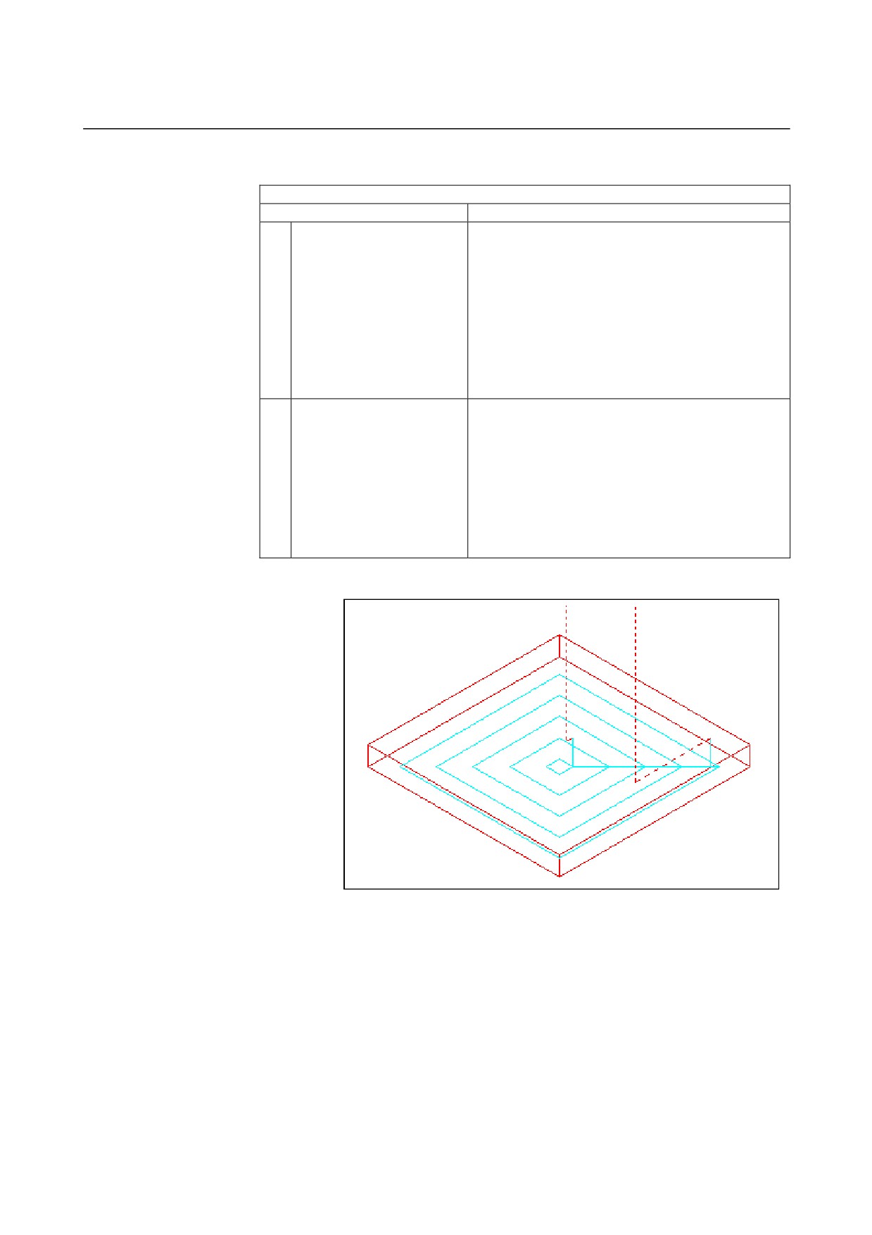
• Tool path
The bottom surface of a pocket machining profile is finished in a
spiral manner.
The tool path for it is the same as for pocketing (roughing).
See descriptions about pocketing (roughing) for details.
No in-feed machining in the tool axis direction is performed, though.
The top surface of island machining profiles is not cut off either.
- 429 -
1.MILLING
CYCLE MACHINING TYPES
B-63874EN/05
Side face finish: G1042
TOOL COND.
Data item
Meaning
I
INPUT
[INPUT] : Inputs a cutter compensation value directly.
[REF.]
: Inputs a cutter compensation number to
read a cutter compensation value by that
number.
D
TOOL DIAMETER
End mill diameter (positive value)
Remark) This item is indicated only when [INPUT] is
selected for INPUT.
M
CUTTER COMP.NO.
Cutter compensation number of an end mill (positive
value)
Remark) This item is indicated only when [REF.] is
selected for INPUT.
NOTE
1 Tab ‘TOOL COND.’ is enabled when bit 0 (TLG) of
parameter No. 27002 = 1.
2 The operator ordinarily sets the above data on the
tab of ‘TOOL DATA’ in Tool Offset window.
Therefore, it is not necessary to display the tab
‘TOOL COND.’
3 Tab ‘TOOL COND.’ is not enabled when bit 3 (PF3)
of parameter No. 27061 = 1.
CUT COND.
Data item
Meaning
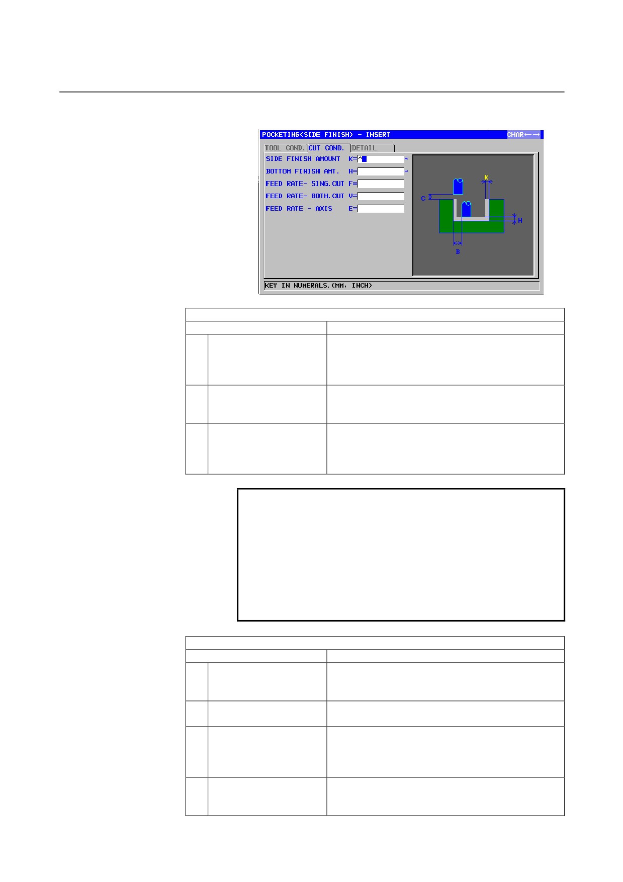
K*
SIDE FINISH AMOUNT
Finishing allowance on the side face of a pocket.
The blank is regarded as 0. (radius value, positive
value)
H*
BOTTOM FINISHI AMT.
Finishing allowance at the bottom of a pocket. The
blank is regarded as 0. (radius value, positive value)
F
FEED RATE- SING.CUT
Feedrate applicable when only the one-side cutter
portion of an end mill is used for cutting. This feedrate
is used for cutting in retract operation and on the side
face other than initial cutting.
V
FEED RATE- BOTH.CUT
Feedrate applicable when the entire front side of an
end mill is used for cutting. This feedrate is used for
initial cutting.
- 430 -
B-63874EN/05
CYCLE MACHINING TYPES
1.MILLING
CUT COND.
Data item
Meaning
E
FEED RATE- AXIS
Feedrate applicable when cutting is performed in the
tool axis direction toward the bottom of a side face
being machined
DETAIL
Data item
Meaning
W
UP CUT/DOWN CUT
[UP CUT]
: Performs machining in up-cut mode,
assuming that the tool is rotating
clockwise.
[DWNCUT] : Performs machining in down-cut mode,
assuming that the tool is rotating
clockwise.
(COPY)
C
CLEARANCE OF AXIS
Distance between the surface of a blank being
machined and a cutting start point (point R) in the tool
axis direction (radius value, positive value)
Remark) By referring to the parameter No.27009
(minimum clamp value), the system sets the
data as Initial value.
P
APPROACH TYPE
[ARC]
: Approaches a side face along an arc.
[TANGEN]: Approaches a side face along the straight
line tangent to the first figure in side face
cutting.
[VERTIC] : Approaches a side face along the straight
line normal to the first figure in side face
cutting.
(COPY)
R
APPROACH RAD./DIST.
Radius when [ARC] is specified.
Straight line length when [TANGEN] or [VERTIC] is
specified. (radius value, positive value)
Remark) By referring to the parameter No.27010
(minimum clamp value), the system sets the
data as Initial value.
A*
APPROACH ANGLE
Center angle of the arc when [ARC] is specified. The
default is 90 degrees. (positive value)
Remark) This data item is indicated only when [ARC]
is selected for APPROACH TYPE.
(COPY)
Q
ESCAPE TYPE
[ARC]
: Retracts from a side face along an arc.
[TANGEN]: Retracts from a side face along the
straight line tangent to the last figure in
side face cutting.
[VERTIC] : Retracts from a side face along the
straight line normal to the last figure in
side face cutting.
(COPY)
- 431 -