FANUC MANUAL GUIDE i. OPERATOR’S MANUAL - page 14
1.MILLING
CYCLE MACHINING TYPES
B-63874EN/05
DETAIL
Data item
Meaning
A
CUTTING DIRECTION
[RIGHT] : Performs cutting rightward as indicated
in the illustration. When both directions
are selected, cutting for the first cutting
path is performed rightward.
[LEFT]
: Performs cutting leftward as indicated in
the illustration. When both directions
are selected, cutting for the first cutting
path is performed leftward.
[UP]
: Performs cutting upward as indicated in
the illustration. When both directions
are selected, cutting for the first cutting
path is performed upward.
[DOWN] : Performs cutting downward as indicated
in the illustration. When both directions
are selected, cutting for the first cutting
path is performed downward.
Remark) The actual cutting direction is determined
by the coordinate axis indicated in the
illustration.
(COPY)
B
CUT DEPTH DIRECTION
[RIGHT] : Performs cutting while shifting the
cutting path rightward as indicated in
the illustration.
[LEFT]
: Performs cutting while shifting the
cutting path leftward as indicated in the
illustration.
[UP]
: Performs cutting while shifting the
cutting path upward as indicated in the
illustration.
[DOWN] : Performs cutting while shifting the
cutting path downward as indicated in
the illustration.
Remark) The actual cutting direction is determined
by the coordinate axis indicated in the
illustration.
(COPY)
Z
APROCH MOTION
[2 AXES]
: When moving from the current
position to the machining start point,
the tool first moves in the machining
plane in two-axis synchronous
operation and then moves along the
tool axis. (initial value)
[3 AXES]
: The tool moves from the current
position to the machining start point in
three-axis synchronous operation.
- 372 -
B-63874EN/05
CYCLE MACHINING TYPES
1.MILLING
Finish: G1021
TOOL COND.
Data item
Meaning
D
TOOL DIAMETER
Face mill diameter
NOTE
1 Tab ‘TOOL COND.’ is enabled when bit 0 (TLG) of
parameter No. 27002 = 1.
2 The operator ordinarily sets the above data on the
tab of ‘TOOL DATA’ in Tool Offset window.
Therefore, it is not necessary to display the tab
‘TOOL COND.’
CUT COND.
Data item
Meaning
L
CUT DEPTH OF RADIUS
Depth of cut in the tool radius direction to the next
cutting path
F
FEED RATE - RADIUS
Feedrate applicable when cutting is performed in
the tool radius direction
E
FEED RATE - AXIS
Feedrate applicable when cutting is performed in
the tool axis direction
- 373 -

1.MILLING
CYCLE MACHINING TYPES
B-63874EN/05
DETAIL
Data item
Meaning
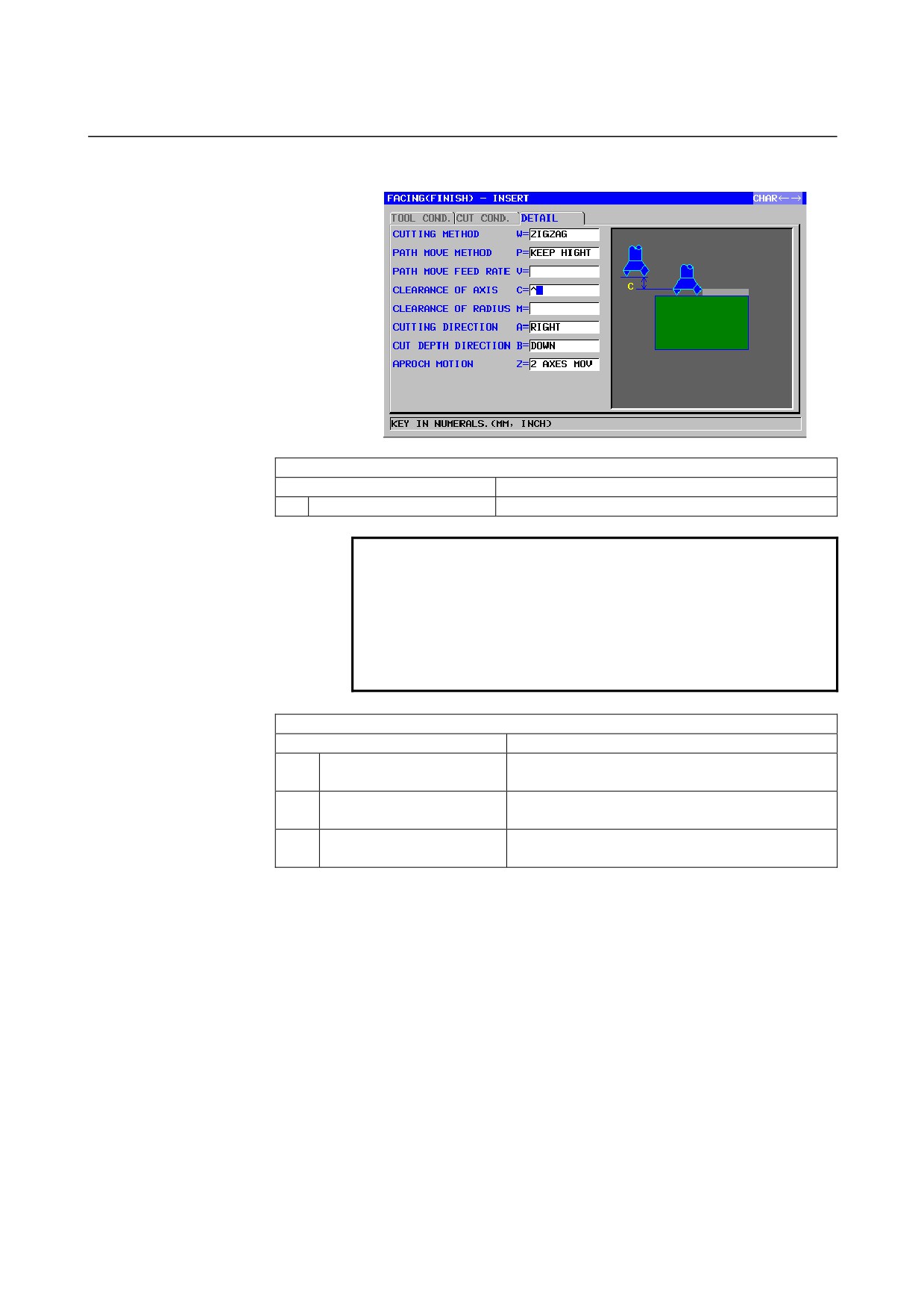
W
CUTTING METHOD
[SINGLE] : Cutting in the tool radius direction is
always performed in the same
direction.
[ZIGZAG] : Cutting in the tool radius direction is
performed back and forth.
(COPY)
P
PATH MOVE METHOD
[PULL]
: Retracts to point R before moving to the
start point of the next cutting path (in
the tool axis direction).
[KEEP]
: Moves to the start point of the next
cutting path directly without retracting to
point R.
Remark1) This data item is indicated only when
[ZIGZAG] is selected for CUTTING
METHOD, and [KEEP] is set
automatically.
Remark2) This data item is enabled when the
parameter No.27030#0(FC0) = 1.
(COPY)
V
PATH MOVE FEED RATE
Feedrate applicable when the tool moves to the
start point of the next cutting path. Initially, the
feedrate is set to 0, allowing the tool to move at a
rapid traverse rate.
(COPY)
Remark1) This data item is indicated only when
[ZIGZAG] is selected for CUTTING
METHOD.
Remark2) This data item is enabled when the
parameter No.27030#0(FC0) = 1.
C
CLEARANCE OF AXIS
Distance between the surface of a blank being
machined and a cutting start point (point R) in the
tool axis direction (radius value)
Remark) By referring to the parameter No.27009
(minimum clamp value), the system sets
the data as Initial value.
M
CLERANCE OF RADIUS
Distance between the end of a blank being
machined and the end of the tool placed at the
retract position (radius value)
Remark) By referring to the parameter No.27009
(minimum clamp value), the system sets
the data as Initial value.
- 374 -
B-63874EN/05
CYCLE MACHINING TYPES
1.MILLING
DETAIL
Data item
Meaning
A
CUTTING DIRECTION
[RIGHT] : Performs cutting rightward as indicated
in the illustration. When both directions
are selected, cutting for the first cutting
path is performed rightward.
[LEFT]
: Performs cutting leftward as indicated in
the illustration. When both directions
are selected, cutting for the first cutting
path is performed leftward.
[UP]
: Performs cutting upward as indicated in
the illustration. When both directions
are selected, cutting for the first cutting
path is performed upward.
[DOWN] : Performs cutting downward as indicated
in the illustration. When both directions
are selected, cutting for the first cutting
path is performed downward.
Remark) The actual cutting direction is determined
by the coordinate axis indicated in the
illustration.
(COPY)
B
CUT DEPTH DIRECTION
[RIGHT] : Performs cutting while shifting the
cutting path rightward as indicated in
the illustration.
[LEFT]
: Performs cutting while shifting the
cutting path leftward as indicated in the
illustration.
[UP]
: Performs cutting while shifting the
cutting path upward as indicated in the
illustration.
[DOWN] : Performs cutting while shifting the
cutting path downward as indicated in
the illustration.
Remark) The actual cutting direction is determined
by the coordinate axis indicated in the
illustration.
(COPY)
Z
APROCH MOTION
[2 AXES]
: When moving from the current
position to the machining start point,
the tool first moves in the machining
plane in two-axis synchronous
operation and then moves along the
tool axis. (initial value)
[3 AXES]
: The tool moves from the current
position to the machining start point in
three-axis synchronous operation.
NOTE
When a cutting direction is selected, only those
menu items that are perpendicular to the cutting
direction can be displayed to delete unnecessary
options by setting bit 1 of parameter No. 27030 to 1.
- 375 -
1.MILLING
CYCLE MACHINING TYPES
B-63874EN/05
1.3.2
Fixed Form Figure Blocks for Facing (XY Plane)
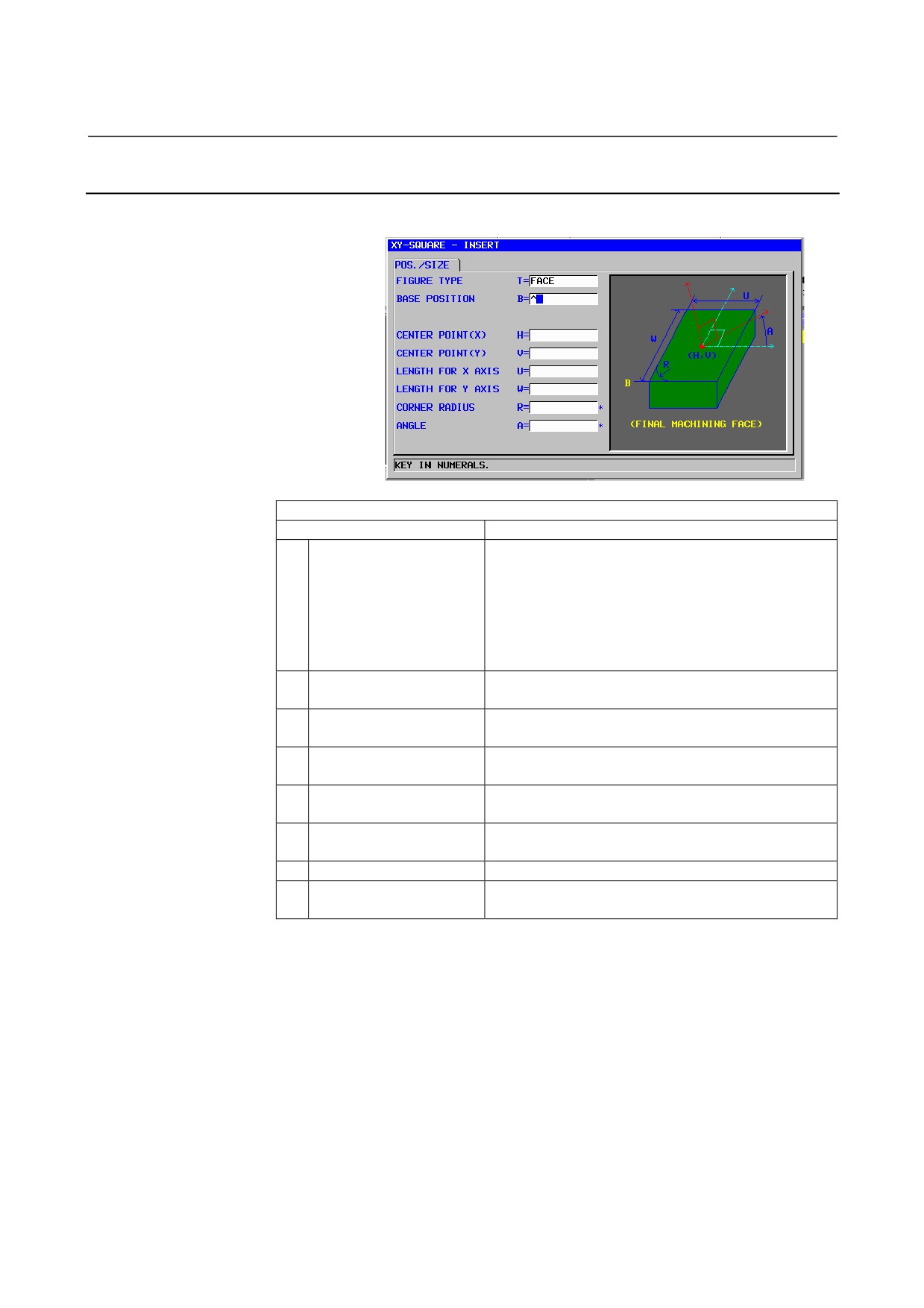
Square: G1220 (XY plane)
POS./SIZE
Data item
Meaning
T
FIGURE TYPE
[FACE]
: Used as a figure for facing
[CONVEX]
: Used as an outer figure for contouring
[CONCAVE] : Used as an inner figure for contouring
or as a figure for pocketing
[GROOVE] : Used as a figure for grooving
Remark) When facing is selected as machining type,
be sure to select [FACE].
B
BASE POSITION
Z coordinate of the final surface for facing (in the tool
axis direction)
H
CENTER POINT (X)
X coordinate of the center position of a rectangular
figure
V
CENTER POINT (Y)
Y coordinate of the center position of a rectangular
figure
U
LEBGTH FOR X AXIS
Length of the side in the X-axis direction (radius value,
positive value)
W
LENGTH FOR Y AXIS
Length of the side in the Y-axis direction (radius value,
positive value)
R*
CORNER RADIUS
Radius for corner rounding (positive value)
A*
ANGLE
Inclination angle of a rectangular figure relative to the
X-axis (positive or negative value)
- 376 -
B-63874EN/05
CYCLE MACHINING TYPES
1.MILLING
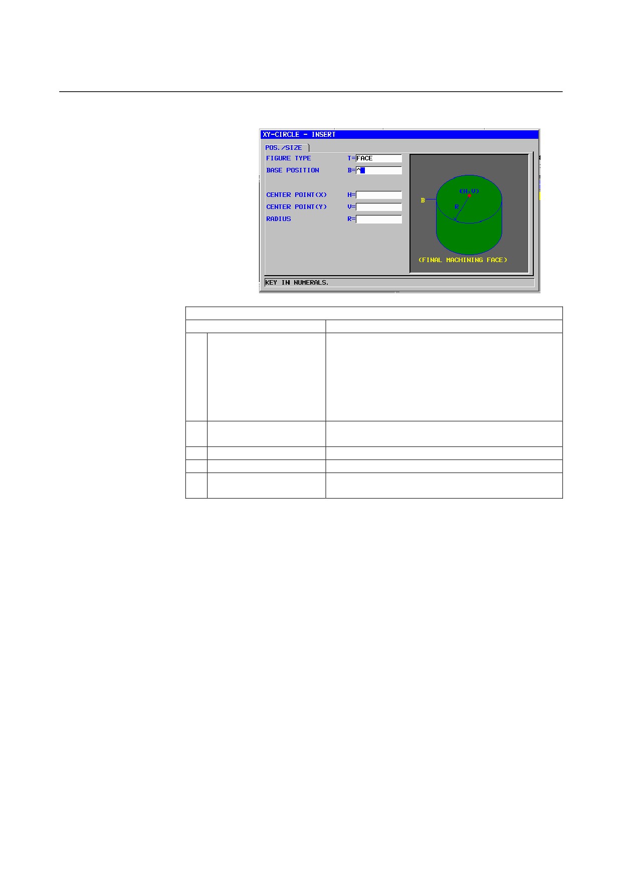
Circle: G1221 (XY plane)
POS./SIZE
Data item
Meaning
T
FIGURE TYPE
[FACE]
: Used as a figure for facing
[CONVEX]
: Used as an outer figure for contouring
[CONCAVE] : Used as an inner figure for contouring
or as a figure for pocketing
[GROOVE] : Used as a figure for grooving
Remark) When facing is selected as machining type,
be sure to select [FACE].
B
BASE POSITION
Z coordinate of the final surface for facing (in the tool
axis direction)
H
CENTER POINT (X)
X coordinate of the center position of a circular figure
V
CENTER POINT (Y)
Y coordinate of the center position of a circular figure
R
RADIUS
Radius of a circular figure (radius value, positive
value)
- 377 -
1.MILLING
CYCLE MACHINING TYPES
B-63874EN/05
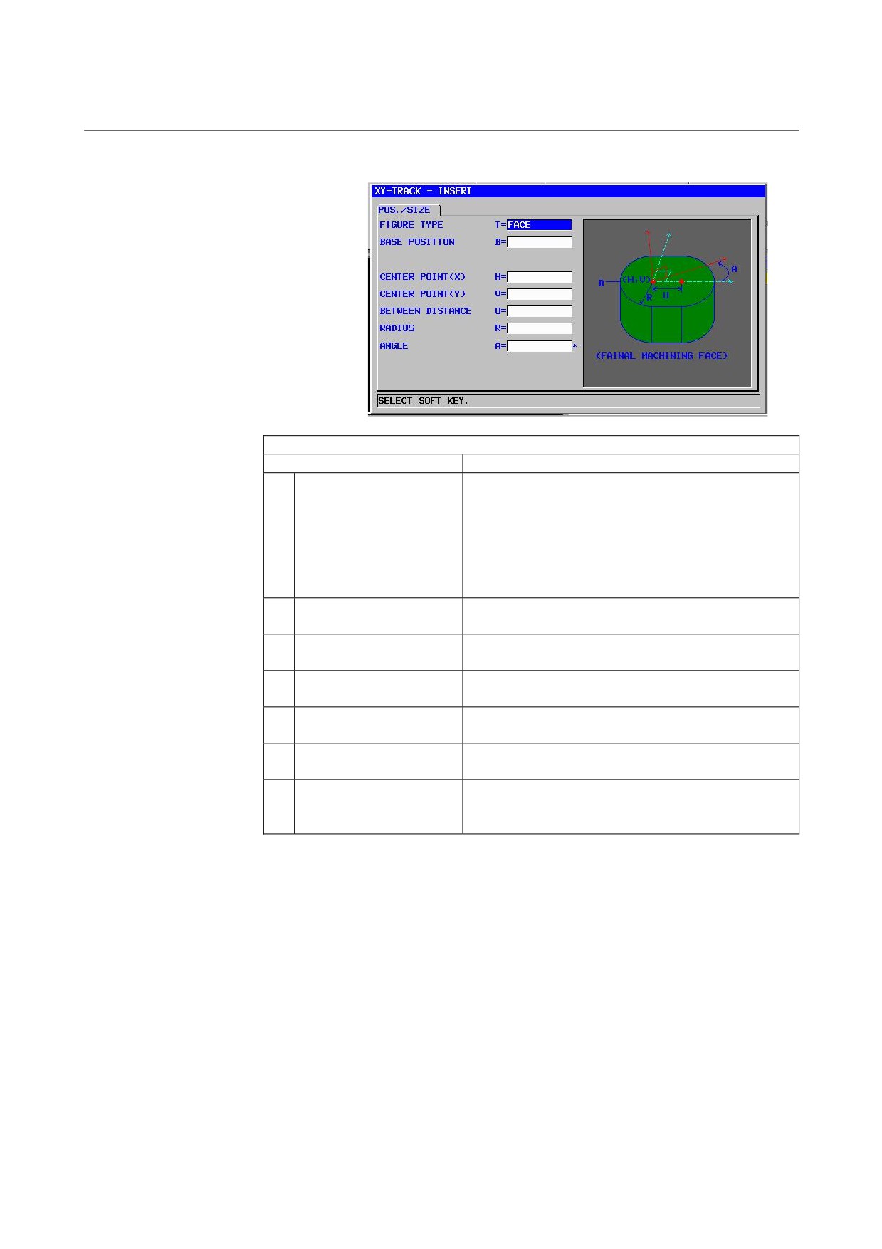
Track: G1222 (XY plane)
POS./SIZE
Data item
Meaning
T
FIGURE TYPE
[FACE]
: Used as a figure for facing
[CONVEX]
: Used as an outer figure for contouring
[CONCAVE] : Used as an inner figure for contouring
or as a figure for pocketing
[GROOVE] : Used as a figure for grooving
Remark) When facing is selected as machining type,
be sure to select [FACE].
B
BASE POSITION
Z coordinate of the final surface for facing (in the tool
axis direction)
H
CENTER POINT (X)
X coordinate of the center position of the left
semicircle
V
CENTER POINT (Y)
Y coordinate of the center position of the left
semicircle
U
BETWEEN DISTANCE
Distance between the centers of the right and left
semicircles (radius value, positive value)
R
RADIUS
Radius of the left and right semicircles (radius value,
positive value)
A*
ANGLE
Inclination angle of a track figure relative to the X-axis.
The blank is regarded as 0 degrees. (positive or
negative value)
- 378 -
B-63874EN/05
CYCLE MACHINING TYPES
1.MILLING
1.3.3
Fixed Form Figure Blocks for Facing (YZ Plane, XC Plane)
The same fixed-figure block types as for the XY plane explained in
the previous subsection are available for the YZ plane and the XC
plane (polar coordinate interpolation plane). They are provided with
the following G codes.
The data to be set for the YZ and XC planes is the same as for the XY
plane except that the XY plane is changed to the YZ or XC plane and
that the direction in which the tool moves to cut is changed to the
X-axis (YZ plane) or the Z-axis (XC plane).
Square
: G1320 (YZ plane)
Circle
: G1321 (YZ plane)
Track
: G1322 (YZ plane)
Square
: G1520 (XC plane, polar coordinate interpolation plane)
Circle
: G1521 (XC plane, polar coordinate interpolation plane)
Track
: G1522 (XC plane, polar coordinate interpolation plane)
NOTE
When performing machining (polar coordinate
interpolation) on the XC plane, note the following:
(When bit 2 of parameter No. 27000 = 0)
The mode needs to be switched to the polar
coordinate interpolation mode beforehand.
Specifically, enter G12.1 before the machining
type.
Enter G13.1 for canceling polar coordinate
interpolation as required.
(When bit 2 of parameter No. 27000 = 1)
G12.1 and G13.1 are automatically output before
and after cycle machining, respectively.
- 379 -
1.MILLING
CYCLE MACHINING TYPES
B-63874EN/05
1.3.4
Arbitrary Figure Blocks for Facing (XY Plane)
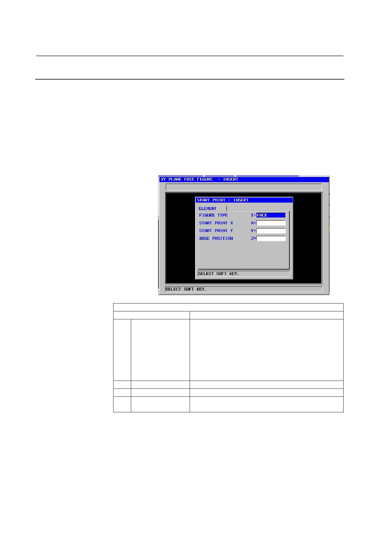
When an arbitrary figure for facing is input, data such as a figure type
and machining reference position is specified in the start point block.
Other data items to be input such as a straight line and arc are exactly the
same as for arbitrary figures of other machining types.
So, this subsection describes only the start point block of an arbitrary
figure for facing.
For other arbitrary figures, see Chapter
5, "DETAILED
DESCRIPTIONS ABOUT ENTERING ARBITRARY FIGURES," in
Part II.
Start point: G1200 (XY plane)
ELEMENT
Data item
Meaning
T
FIGURE TYPE
[FACE]
: Used as a figure for facing
[CONVEX]
: Used as an outer figure for contouring
[CONCAVE] : Used as an inner figure for contouring and
emboss machining or as a figure for
pocketing
[GROOVE] : Used as a figure for grooving
Remark) When facing is selected as machining type, be
sure to select [FACE].
X
START POINT X
X coordinate of the start point of an arbitrary figure
Y
START POINT Y
Y coordinate of the start point of an arbitrary figure
Z
BASE POSITION
Z coordinate of the final surface for facing (in the tool axis
direction)
- 380 -
B-63874EN/05
CYCLE MACHINING TYPES
1.MILLING
1.3.5
Arbitrary Figure Blocks for Facing (YZ Plane, XC Plane, ZC
Plane, XA Plane)
The same arbitrary-figure block types as for the XY plane explained
in the previous subsection are available for the YZ plane, the XC
plane (polar coordinate interpolation plane), ZC plane and XA plane
(cylindrical surface). Their start points are specified with the
following G codes.
The data to be set for the YZ, XC, ZC, and XA planes is the same as
for the XY plane except that the XY plane is changed to the YZ, XC,
ZC or XA plane and that the direction in which the tool moves to cut
is changed to the X-axis (YZ and ZC planes) or the Z-axis (XC and
XA plane).
Start point : G1300 (YZ plane)
Start point : G1500 (XC plane, polar coordinate interpolation plane)
Start point : G1600 (ZC plane, plane)
Start point : G1700 (XA plane, plane)
NOTE
1
When performing machining (polar coordinate
interpolation) on the XC plane, note the following:
(When bit 2 of parameter No. 27000 = 0)
The mode needs to be switched to the polar
coordinate interpolation mode beforehand.
Specifically, enter G12.1 before the machining
type.
Enter G13.1 for canceling polar coordinate
interpolation as required.
(When bit 2 of parameter No. 27000 = 1)
G12.1 and G13.1 are automatically output before
and after cycle machining, respectively.
2
When performing machining (cylindrical
interpolation) on the ZC and XA plane, note the
following:
(When bit 3 of parameter No. 27000 = 0)
The mode needs to be switched to the cylindrical
coordinate interpolation mode beforehand.
Specifically, enter G07.1C (cylinder radius) before
the machining type.
Enter G07.1C0 for canceling cylindrical
interpolation as required.
(When bit 3 of parameter No. 27000 = 1)
G07.1C (cylinder radius) and G07.1C0 are
automatically output before and after cycle
machining, respectively.
3
The following parameter setting is necessary to
execute XA plane cycle.
• No.27003#2=1, 27003#1=0 and 27003#0=0
- 381 -
1.MILLING
CYCLE MACHINING TYPES
B-63874EN/05
1.4
CONTOURING
1.4.1
Machining Type Blocks for Contouring
Outer Wall Rough: G1060
Inner Wall Rough: G1054
Partial Rough: G1068
TOOL COND.
Data item
Meaning
D
TOOL DIAMETER
End mill diameter
NOTE
1 Tab ‘TOOL COND.’ is enabled when bit 0 (TLG) of
parameter No. 27002 = 1.
2 The operator ordinarily sets the above data on the
tab of ‘TOOL DATA’ in Tool Offset window.
Therefore, it is not necessary to display the tab
‘TOOL COND.’
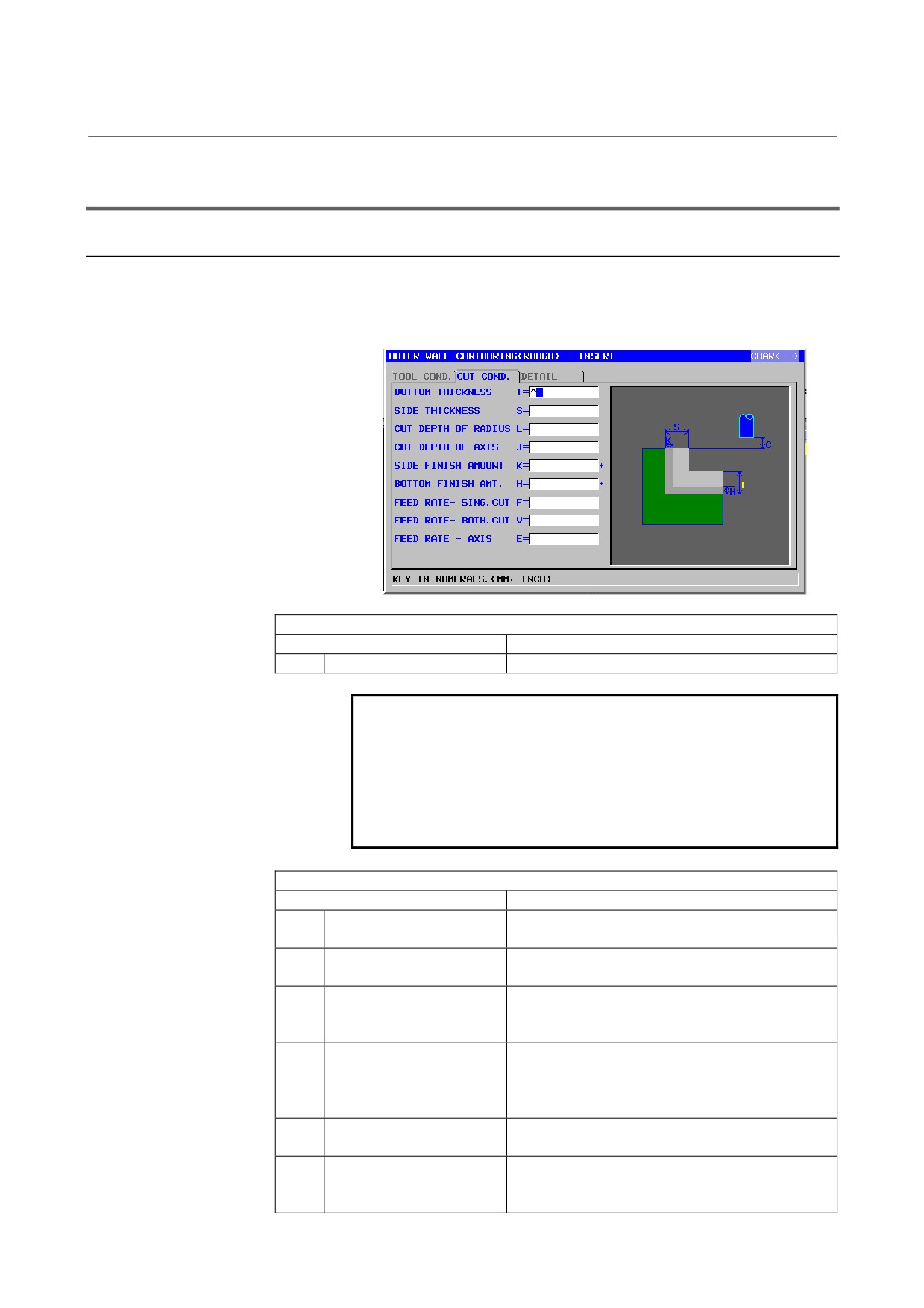
CUT COND
Data item
Meaning
T
BOTTOM THICKNESS
Cutting allowance of the bottom in side face
machining (radius value, positive value)
S
SIDE THICKNESS
Cutting allowance of the side face (radius value,
positive value)
L
CUT DEPTH OF RADIUS
Depth of cut per side face machining operation (in
the tool radius direction) (radius value, positive
value)
J
CUT DEPTH OF AXIS
Depth of cut in the tool axis direction per cutting
operation (radius value, positive value)
The default is (bottom surplus thickness - bottom
finishing allowance).
K*
SIDE FINISH AMOUNT
Finishing allowance on the side face. The blank is
regarded as 0. (radius value, positive value)
H*
BOTTOM FINISHI AMT.
Finishing allowance at the bottom in side face
machining. The blank is regarded as 0. (radius
value, positive value)
- 382 -
B-63874EN/05
CYCLE MACHINING TYPES
1.MILLING
CUT COND
Data item
Meaning
F
FEED RATE- SING.CUT
Feedrate applicable when only the one-side cutter
portion of an end mill is used for cutting. This
feedrate is used for cutting in retract operation and
on the side face other than initial cutting.
V
FEED RATE- BOTH CUT
Feedrate applicable when the entire front side of
an end mill is used for cutting. This feedrate is
used for initial cutting.
E
FEED RATE - AXIS
Feedrate applicable when cutting is performed in
the tool axis direction toward the bottom of a side
face being machined
DETAIL
Data item
Meaning
M
INITIAL FEED OVERRIDE
Feedrate override value for the first cutting. The
initial value is 100 (1 to 200, positive value).
W
UP CUT/DOWN CUT
[UP CUT]
: Performs machining in up-cut mode,
assuming that the tool is rotating
clockwise.
[DWNCUT] : Performs machining in down-cut
mode, assuming that the tool is
rotating clockwise.
(COPY)
C
CLEARANCE OF AXIS
Distance between the surface of a blank being
machined and a cutting start point (point R) in the
tool axis direction (radius value, positive value)
Remark) By referring to the parameter No.27009
(minimum clamp value), the system sets
the data as Initial value.
P
APPROACH TYPE
[ARC]
: Approaches a side face along an arc.
[TANGEN]: Approaches a side face along the
straight line tangent to the first figure
in side face cutting.
[VERTIC] : Approaches a side face along the
straight line normal to the first figure in
side face cutting.
(COPY)
R
APPROACH RAD./DIST.
Radius when [ARC] is specified.
Straight line length when [TANGEN] or [VERTIC]
is specified. (radius value, positive value)
Remark) By referring to the parameter No.27010
(minimum clamp value), the system sets
the data as Initial value.
A*
APPROACH ANGLE
Center angle of the arc when [ARC] is specified.
The default is 90 degrees. (positive value)
Remark) This data item is indicated only when
[ARC] is selected for APPROACH TYPE.
(COPY)
- 383 -

1.MILLING
CYCLE MACHINING TYPES
B-63874EN/05
DETAIL
Data item
Meaning
Q
ESCAPE TYPE
[ARC]
: Retracts from a side face along an
arc.
[TANGEN]: Retracts from a side face along the
straight line tangent to the last figure
in side face cutting.
[VERTIC] : Retracts from a side face along the
straight line normal to the last figure in
side face cutting.
(COPY)
X
ESCAPE RAD./DIST.
Radius when [ARC] is specified.
Straight line length when [TANGEN] or [VERTIC]
is specified. (radius value, positive value)
Remark) By referring to the parameter No.27010
(minimum clamp value), the system sets
the data as Initial value.
Y*
ESCAPE ANGLE
Center angle of the arc when [ARC] is specified.
The default is 90 degrees. (positive value)
Remark) This data item is indicated only when
[ARC] is selected for ESCAPE TYPE.
(COPY)
Z
APROCH MOTION
[2 AXES]
: When moving from the current
position to the machining start point,
the tool first moves in the machining
plane in two-axis synchronous
operation and then moves along the
tool axis. (initial value)
[3 AXES]
: The tool moves from the current
position to the machining start point in
three-axis synchronous operation.
- 384 -
B-63874EN/05
CYCLE MACHINING TYPES
1.MILLING
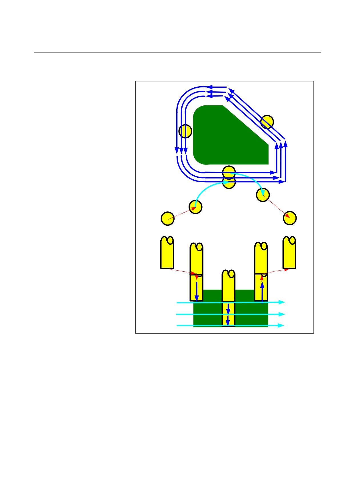
• Tool path
In-feed machining
in the tool radius
direction
Approach
Retract
In-feed machining
in the tool axis
direction
The side-face contour of a machining profile is cut off.
The following tool path is created.
<1> The tool moves to above the approach start point.
<2> The tool moves to the height of the cutting surface.
<3> The tool cuts along the side-face contour of the machining
profile.
The tool performs in-feed machining in the tool radius direction until
the cutting allowance in the tool radius direction is removed.
<4> Steps <2> and <3> are repeated until the cutting allowance in the
tool axis direction is removed.
<5> The tool retracts.
- 385 -
1.MILLING
CYCLE MACHINING TYPES
B-63874EN/05
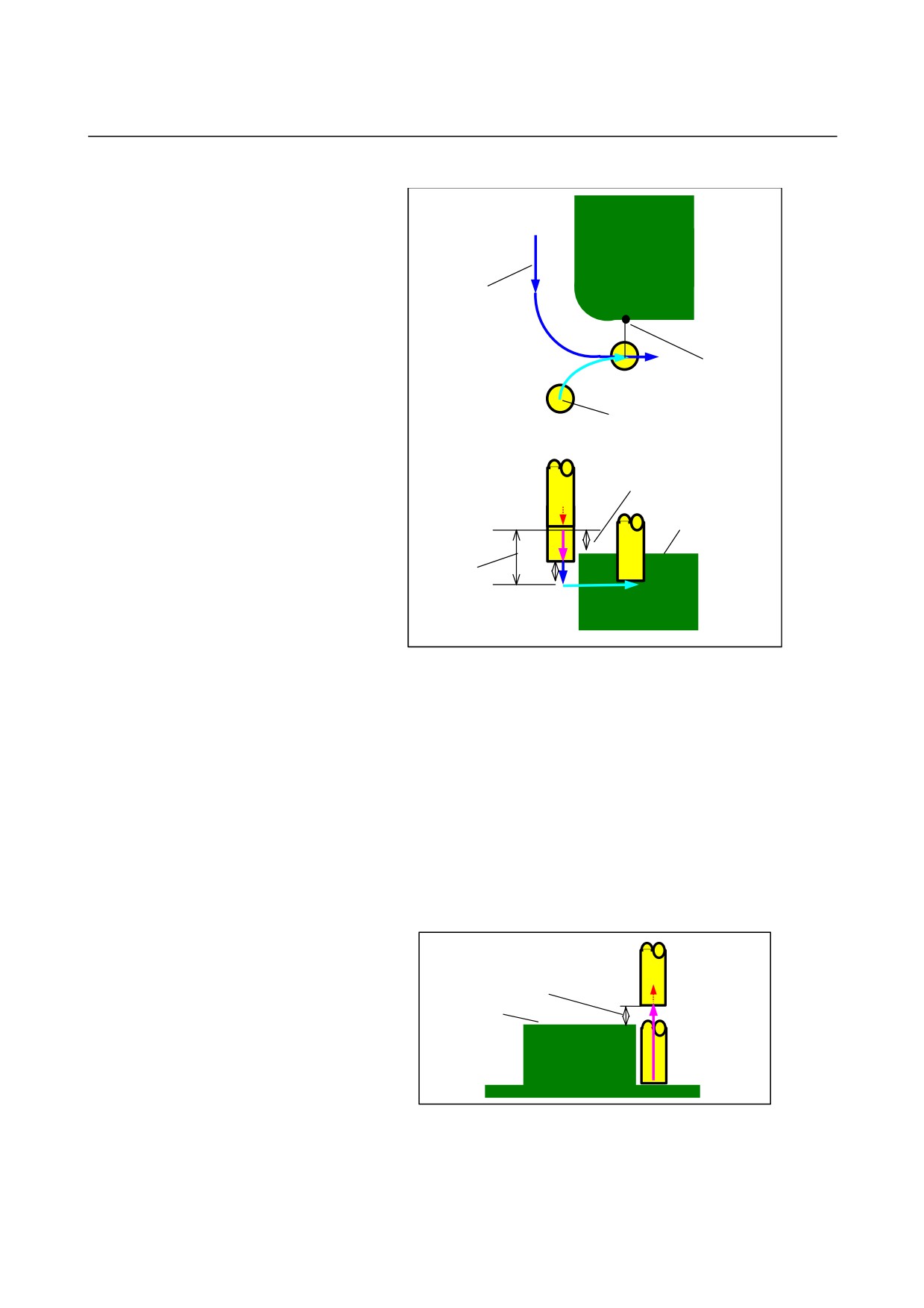
- Approach
First in-feed
machining cycle
in the tool radius
direction
Cutting start point
Approach start point
Clearance Ct in the tool axis direction
Machining profile top
surface height
Amount cut in the
Ftm
first in-feed
machining cycle
Ft
in the tool axis
direction
<1> The tool moves to the position "machining profile top surface
height
+ clearance
(Ct) in the tool axis direction" by rapid
traverse.
<2> The tool moves to the position "amount to be cut in the first
in-feed machining cycle in the tool axis direction - clearance (Ct)
in the tool axis direction" at the feedrate
(Ftm) specified for
movement in the tool axis direction.
<3> The tool cut in to the position "amount to be cut in the first
in-feed machining cycle in the tool axis direction" at the feedrate
(Ft) specified for cutting in the tool axis direction.
<4> The tool approaches, in the tool radius direction, the start point of
the first in-feed machining cycle in the tool radius direction.
- Retraction
Clearance (Ct) in the tool axis direction
Machining profile top surface height
Ftm
<1> The tool moves from the approach end point to the position
"machining profile top surface height + clearance (Ct) in the tool
axis direction" at the feedrate (Ftm) specified for movement in
the tool axis direction.
- 386 -
B-63874EN/05
CYCLE MACHINING TYPES
1.MILLING
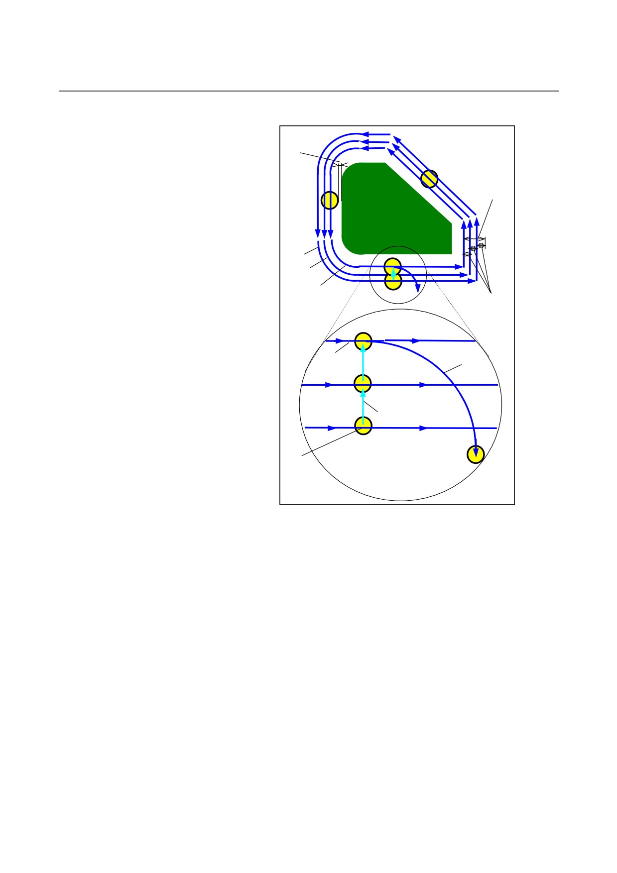
- In-feed machining in the tool radius direction
Finishing
allowance in the
tool radius
direction
Cutting
allowance in the
tool radius
direction
First in-
feed
machining
cycle
Second in-
feed
machining
Third in-feed machining
Amount to be
cut in each in-
feed machining
cycle in the tool
radius direction
Retraction from the wall at
the end of in-feed machining
Feedrate Fr specified for
in the tool radius direction
single-edge thread cutting
Feedrate Fd specified for
double-edge thread cutting
Start and end points of the first in-feed machining cycle
(they coincide in this case)
<1> The tool moves to cut along the contour from the first in-feed
machining cycle start point to the end point at the feedrate (Fs)
specified for single-edge thread cutting.
<2> The tool approaches, using the following method.
When the in-feed machining start point coincides with the in-feed
machining end point:
The tool directly approaches the next in-feed machining start point in
the normal direction at the feedrate (Fd) specified for double-edge
thread cutting.
When the in-feed machining start point does not coincide with the
in-feed machining end point:
The tool approaches the second in-feed machining start point.
<3> The tool moves to cut along the contour of the machining profile
at the feedrate (Fs) specified for single-edge thread cutting.
<4> Steps <2> and <3> are repeated until the cutting allowance
(cutting allowance in the tool radius direction
- finishing
allowance) is removed.
<5> The tool retracts.
- 387 -
1.MILLING
CYCLE MACHINING TYPES
B-63874EN/05
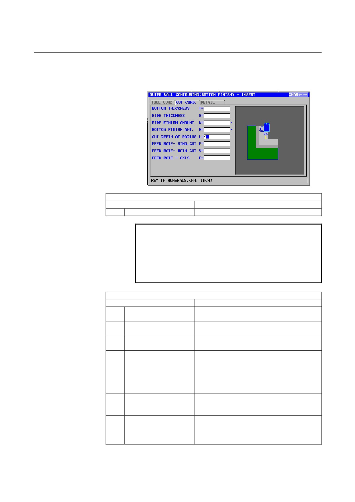
Outer Wall Bottom finish : G1061
Inner Wall Bottom finish : G1065
Partial Bottom finish : G1069
TOOL COND.
Data item
Meaning
D
TOOL DIAMETER
End mill diameter
NOTE
1 Tab ‘TOOL COND.’ is enabled when bit 0 (TLG) of
parameter No. 27002 = 1.
2 The operator ordinarily sets the above data on the
tab of ‘TOOL DATA’ in Tool Offset window.
Therefore, it is not necessary to display the tab
‘TOOL COND.’
CUT COND
Data item
Meaning
T
BOTTOM THICKNESS
Cutting allowance of the bottom in side face
machining (radius value, positive value)
S
SIDE THICKNESS
Cutting allowance of the side face (radius value,
positive value)
K*
SIDE FINISH AMOUNT
Finishing allowance on the side face. The blank
is regarded as 0. (radius value, positive value)
H*
BOTTOM FINISHI AMT.
Finishing allowance at the bottom in side face
machining. The blank is regarded as 0. (radius
value, positive value)
Remark) This data item is used when machining is
to be performed with a small amount of
cutting allowance left.
L
CUT DEPTH OF RADIUS
Depth of cut per side face machining operation (in
the tool radius direction) (radius value, positive
value)
F
FEED RATE- SING.CUT
Feedrate applicable when only the one-side cutter
portion of an end mill is used for cutting. This
feedrate is used for cutting in retract operation and
on the side face other than initial cutting.
- 388 -
B-63874EN/05
CYCLE MACHINING TYPES
1.MILLING
CUT COND
Data item
Meaning
V
FEED RATE- BOTH CUT
Feedrate applicable when the entire front side of
an end mill is used for cutting. This feedrate is
used for initial cutting.
E
FEED RATE- AXIS
Feedrate applicable when cutting is performed in
the tool axis direction toward the bottom of a side
face being machined
DETAIL
Data item
Meaning
W
UP CUT/DOWN CUT
[UP CUT]
: Performs machining in up-cut mode,
assuming that the tool is rotating
clockwise.
[DWNCUT] : Performs machining in down-cut
mode, assuming that the tool is
rotating clockwise.
(COPY)
C
CLEARANCE OF AXIS
Distance between the surface of a blank being
machined and a cutting start point (point R) in the
tool axis direction (radius value, positive value)
Remark) By referring to the parameter No.27009
(minimum clamp value), the system sets
the data as Initial value.
P
APPROACH TYPE
[ARC]
: Approaches a side face along an arc.
[TANGEN]: Approaches a side face along the
straight line tangent to the first figure
in side face cutting.
[VERTIC] : Approaches a side face along the
straight line normal to the first figure in
side face cutting.
(COPY)
R
APPROACH RAD./DIST.
Radius when [ARC] is specified.
Straight line length when [TANGEN] or [VERTIC]
is specified. (radius value, positive value)
Remark) By referring to the parameter No.27010
(minimum clamp value), the system sets
the data as Initial value.
A*
APPROACH ANGLE
Center angle of the arc when [ARC] is specified.
The default is 90 degrees. (positive value)
Remark) This data item is indicated only when
[ARC] is selected for APPROACH TYPE.
(COPY)
Q
ESCAPE TYPE
[ARC]
: Retracts from a side face along an
arc.
[TANGEN]: Retracts from a side face along the
straight line tangent to the last figure
in side face cutting.
[VERTIC] : Retracts from a side face along the
straight line normal to the last figure in
side face cutting.
(COPY)
- 389 -

1.MILLING
CYCLE MACHINING TYPES
B-63874EN/05
DETAIL
Data item
Meaning
X
ESCAPE RAD./DIST.
Radius when [ARC] is specified.
Straight line length when [TANGEN] or [VERTIC]
is specified. (radius value, positive value)
Remark) By referring to the parameter No.27010
(minimum clamp value), the system sets
the data as Initial value.
Y*
ESCAPE ANGLE
Center angle of the arc when [ARC] is specified.
The default is 90 degrees. (positive value)
Remark) This data item is indicated only when
[ARC] is selected for ESCAPE TYPE.
(COPY)
Z
APROCH MOTION
[2 AXES]
: When moving from the current
position to the machining start point,
the tool first moves in the machining
plane in two-axis synchronous
operation and then moves along the
tool axis. (initial value)
[3 AXES]
: The tool moves from the current
position to the machining start point in
three-axis synchronous operation.
- 390 -
B-63874EN/05
CYCLE MACHINING TYPES
1.MILLING
• Tool path
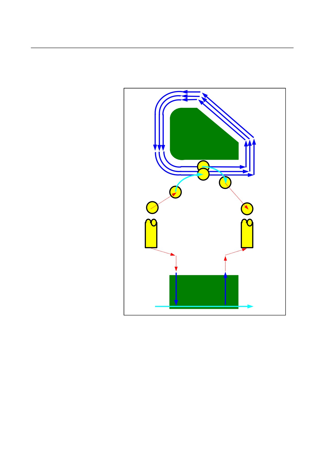
The bottom surface of the side-face contour of the machining profile is
finished.
The following tool path is created.
In-feed machining
in the tool radius
direction
Retract
Approach
<1> The tool approaches the approach start point of the machining
profile.
<2> The tool moves to the bottom surface height of the machining
profile.
<3> The tool moves to cut along the side-face contour of the
machining profile.
In-feed machining in the tool radius direction is performed until the
cutting allowance in the tool radius direction is removed.
<4> The tool retracts.
- 391 -
1.MILLING
CYCLE MACHINING TYPES
B-63874EN/05
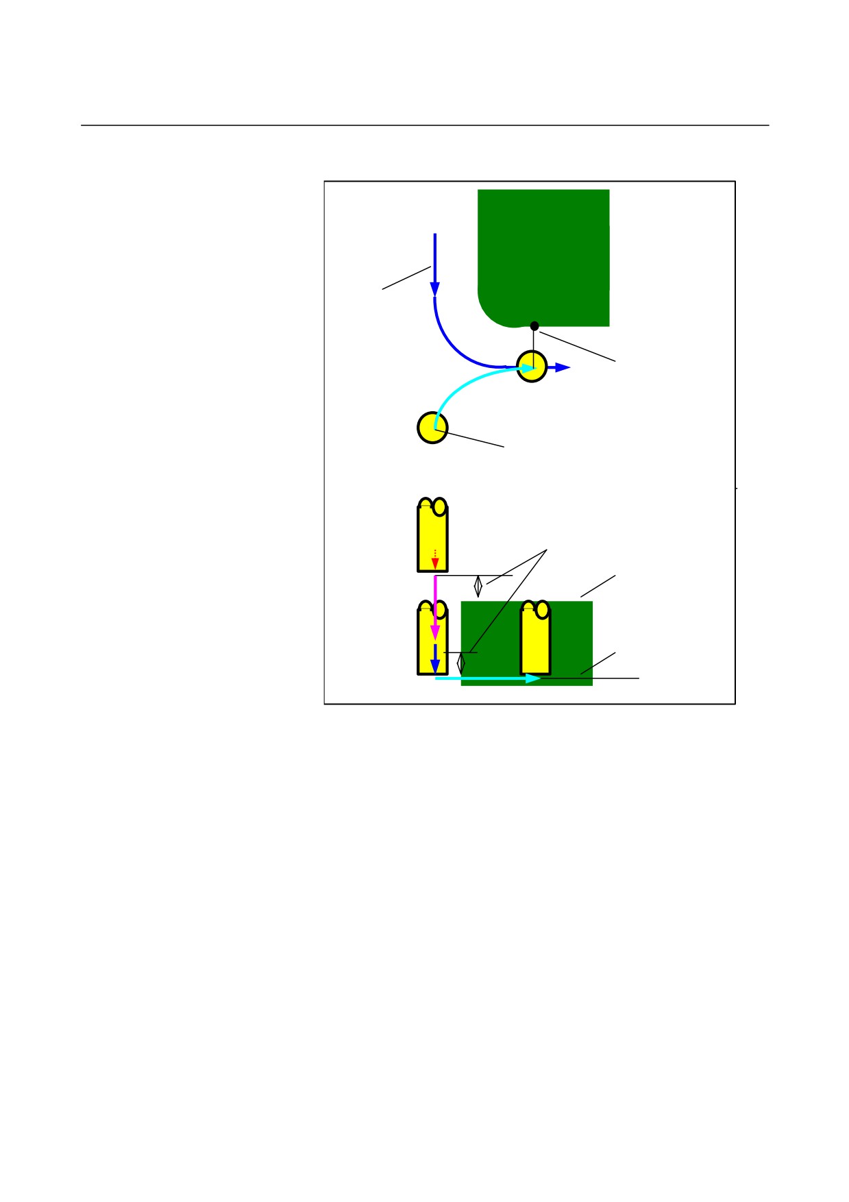
- Approach
First in-feed
machining cycle in
the tool radius
direction
Cutting start point
Approach start point
Clearance Ct in the tool axis direction
Machining profile top
surface height
Ftm
Machining profile
bottom surface
Ft
height
<1> The tool moves to the position "machining profile top surface
height
+ clearance
(Ct) in the tool axis direction" by rapid
traverse.
<2> The tool moves to the position "machining profile bottom surface
+ cutting allowance (Vt) in the tool axis direction + clearance
(Ct) in the tool axis direction" at the feedrate (Ftm) specified for
movement in the tool axis direction.
<3> The tool moves to the machining profile bottom surface at the
feedrate (Ft) specified for cutting in the tool axis direction.
<4> The tool approaches, in the tool radius direction, the in-feed
machining start point in the tool radius direction.
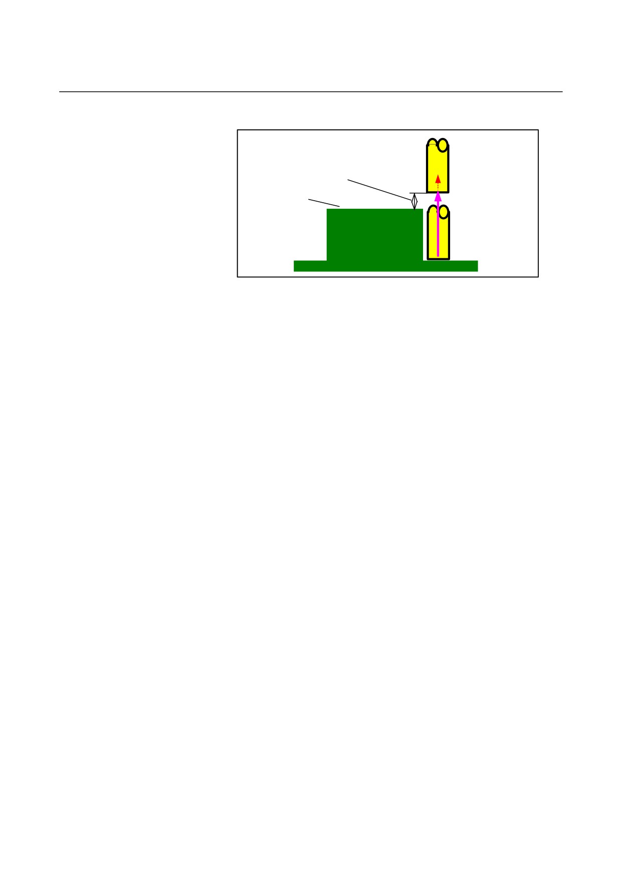
- 392 -
B-63874EN/05
CYCLE MACHINING TYPES
1.MILLING
- Retraction
Clearance Ct in the tool axis direction
Machining profile top
surface height
Ftm
<1> The tool moves from the approach end point to the position
"machining profile top height + clearance (Ct) in the tool axis
direction" at the feedrate (Ftm) specified for movement in the
tool axis direction.
-
In-feed machining in the tool radius direction
This movement is the same as for contouring (roughing).
See descriptions about contouring (roughing) for details.
- 393 -
1.MILLING
CYCLE MACHINING TYPES
B-63874EN/05
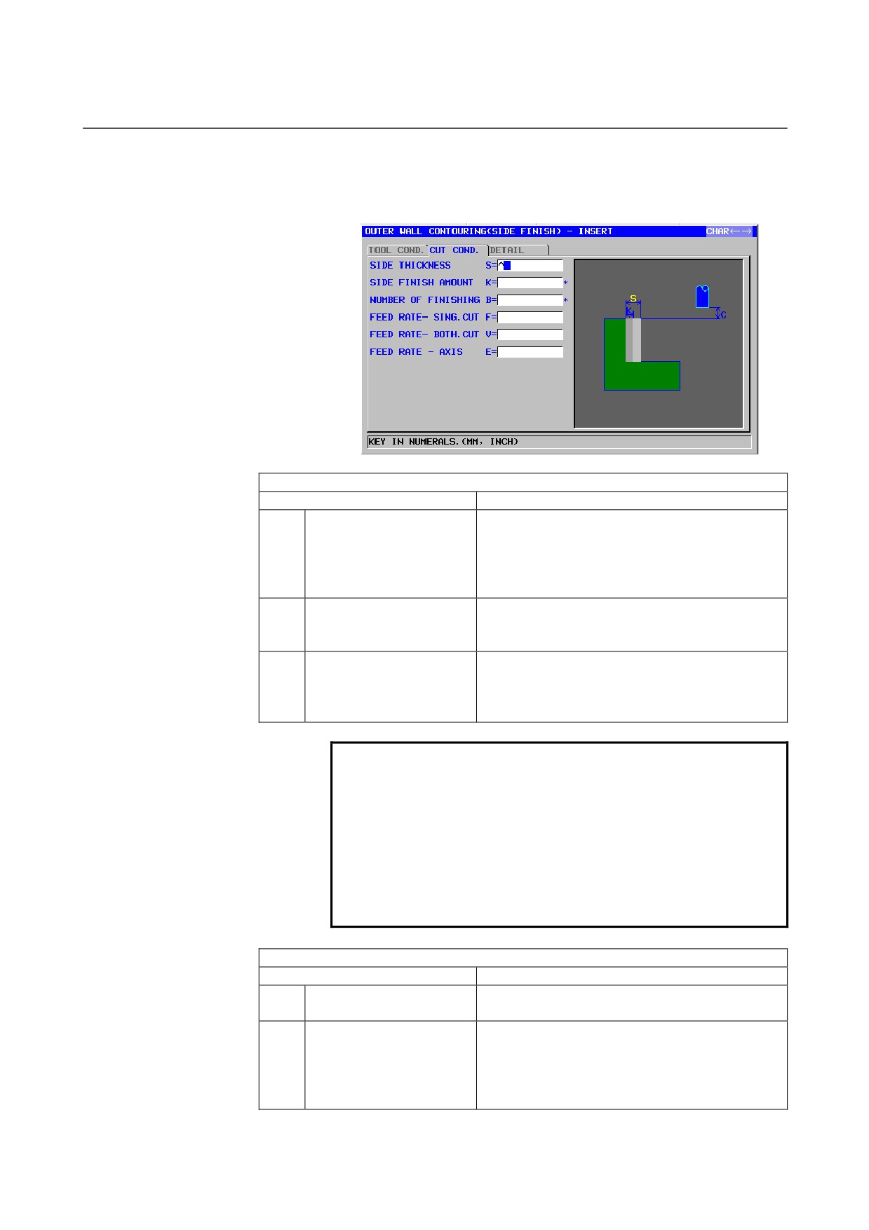
Outer Wall Side finish: G1062
Inner Wall Side finish : G1066
Partial Side finish : G1070
TOOL COND.
Data item
Meaning
I
INPUT TYPE
[INPUT] : Inputs a cutter compensation value
directly.
[REF.]
: Inputs a cutter compensation number to
read a cutter compensation value by
that number.
D
TOOL DIAMETER
End mill diameter (positive value)
Remark) This item is indicated only when [INPUT]
is selected for INPUT TYPE.
M
CUTTER COMP.NO.
Cutter compensation number of an end mill
(positive value)
Remark) This item is indicated only when [REF.] is
selected for INPUT TYPE.
NOTE
1 Tab ‘TOOL COND.’ is enabled when bit 0 (TLG) of
parameter No. 27002 = 1.
2 The operator ordinarily sets the above data on the
tab of ‘TOOL DATA’ in Tool Offset window.
Therefore, it is not necessary to display the tab
‘TOOL COND.’
3 Tab ‘TOOL COND.’ is not enabled when bit 3
(CN3) of parameter No. 27040 = 1.
CUT COND.
Data item
Meaning
S
SIDE THICKNESS
Cutting allowance in side face finishing (radius
value, positive value)
K*
SIDE FINISH AMOUNT
Finishing allowance of the side face. The blank is
regarded as 0. (radius value, positive value)
Remark) This data item is used when machining is
to be performed with a small amount of
cutting allowance left.
- 394 -
B-63874EN/05
CYCLE MACHINING TYPES
1.MILLING
CUT COND.
Data item
Meaning
B
NUMBER OF FINISHING
Number of cuts for finishing (positive value)
Remark) Depth of each cut = (side surplus
thickness)/(number of finishing cuts)
F
FEED RATE- SING.CUT
Feedrate applicable when only the one-side cutter
portion of an end mill is used for cutting. This
feedrate is used for cutting in retract operation and
on the side face other than initial cutting.
V
FEED RATE- BOTH.CUT
Feedrate applicable when the entire front side of
an end mill is used for cutting. This feedrate is
used for initial cutting.
E
FEED RATE- AXIS
Feedrate applicable when cutting is performed in
the tool axis direction toward the bottom of a side
face being machined
DETAIL
Data item
Meaning
W
UP CUT/DOWN CUT
[UP CUT]
: Performs machining in up-cut mode,
assuming that the tool is rotating
clockwise.
[DWNCUT] : Performs machining in down-cut
mode, assuming that the tool is
rotating clockwise.
(COPY)
C
CLEARANCE OF AXIS
Distance between the surface of a blank being
machined and a cutting start point (point R) in the
tool axis direction (radius value, positive value)
Remark) By referring to the parameter No.27009
(minimum clamp value), the system sets
the data as Initial value.
P
APPROACH TYPE
[ARC]
: Approaches a side face along an arc.
[TANGEN]: Approaches a side face along the
straight line tangent to the first figure
in side face cutting.
[VERTIC] : Approaches a side face along the
straight line normal to the first figure in
side face cutting.
(COPY)
R
APPROACH RAD./DIST.
Radius when [ARC] is specified.
Straight line length when [TANGEN] or [VERTIC]
is specified. (radius value, positive value)
Remark) By referring to the parameter No.27010
(minimum clamp value), the system sets
the data as Initial value.
A*
APPROACH ANGLE
Center angle of the arc when [ARC] is specified.
The default is 90 degrees. (positive value)
Remark) This data item is indicated only when
[ARC] is selected for APPROACH TYPE.
(COPY)
- 395 -

1.MILLING
CYCLE MACHINING TYPES
B-63874EN/05
DETAIL
Data item
Meaning
Q
ESCAPE TYPE
[ARC]
: Retracts from a side face along an
arc.
[TANGEN]: Retracts from a side face along the
straight line tangent to the last figure
in side face cutting.
[VERTIC] : Retracts from a side face along the
straight line normal to the last figure in
side face cutting.
(COPY)
X
ESCAPE RAD./DIST.
Radius when [ARC] is specified.
Straight line length when [TANGEN] or [VERTIC]
is specified. (radius value, positive value)
Remark) By referring to the parameter No.27010
(minimum clamp value), the system sets
the data as Initial value.
Y*
ESCAPE ANGLE
Center angle of the arc when [ARC] is specified.
The default is 90 degrees. (positive value)
Remark) This data item is indicated only when
[ARC] is selected for ESCAPE TYPE.
(COPY)
Z
APROCH MOTION
[2 AXES]
: When moving from the current
position to the machining start point,
the tool first moves in the machining
plane in two-axis synchronous
operation and then moves along the
tool axis. (initial value)
[3 AXES]
: The tool moves from the current
position to the machining start point in
three-axis synchronous operation.
- 396 -
B-63874EN/05
CYCLE MACHINING TYPES
1.MILLING
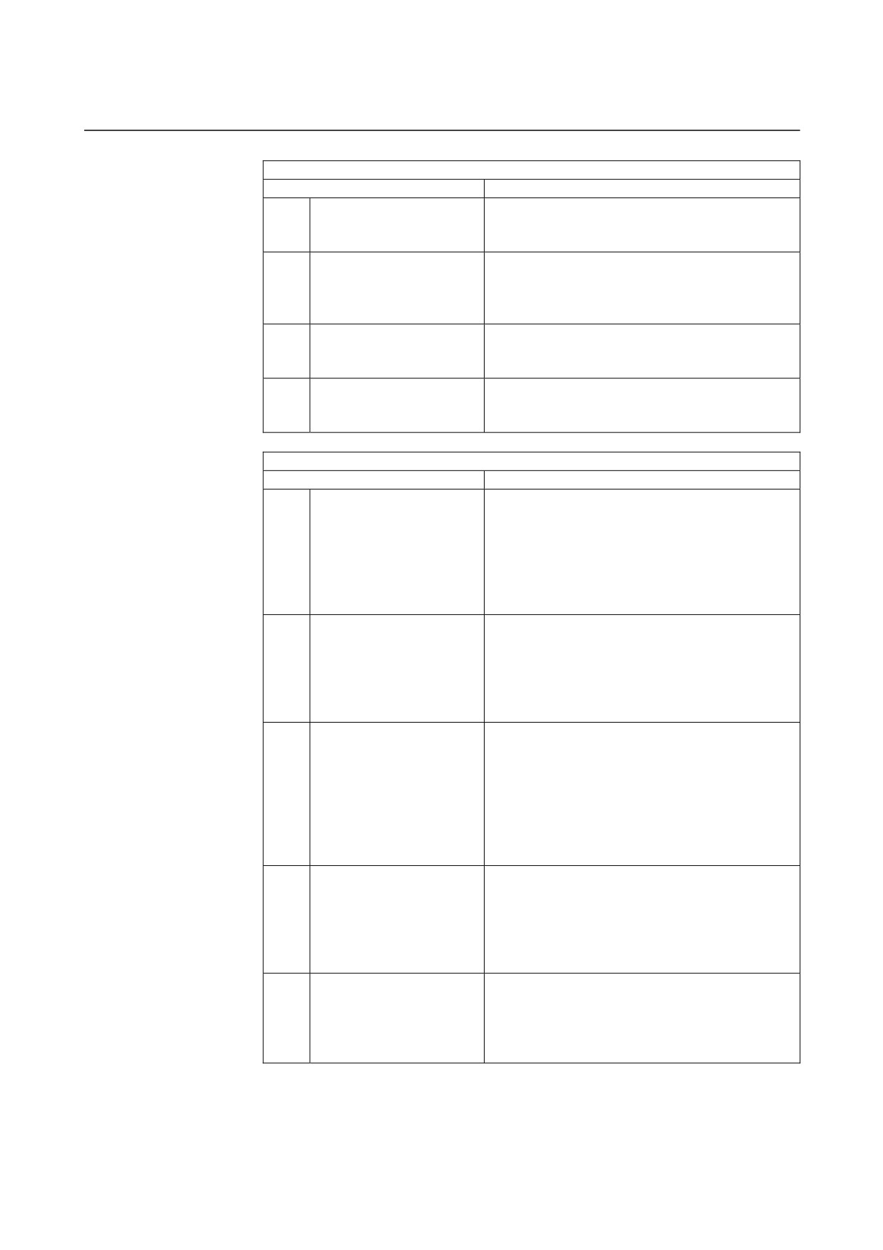
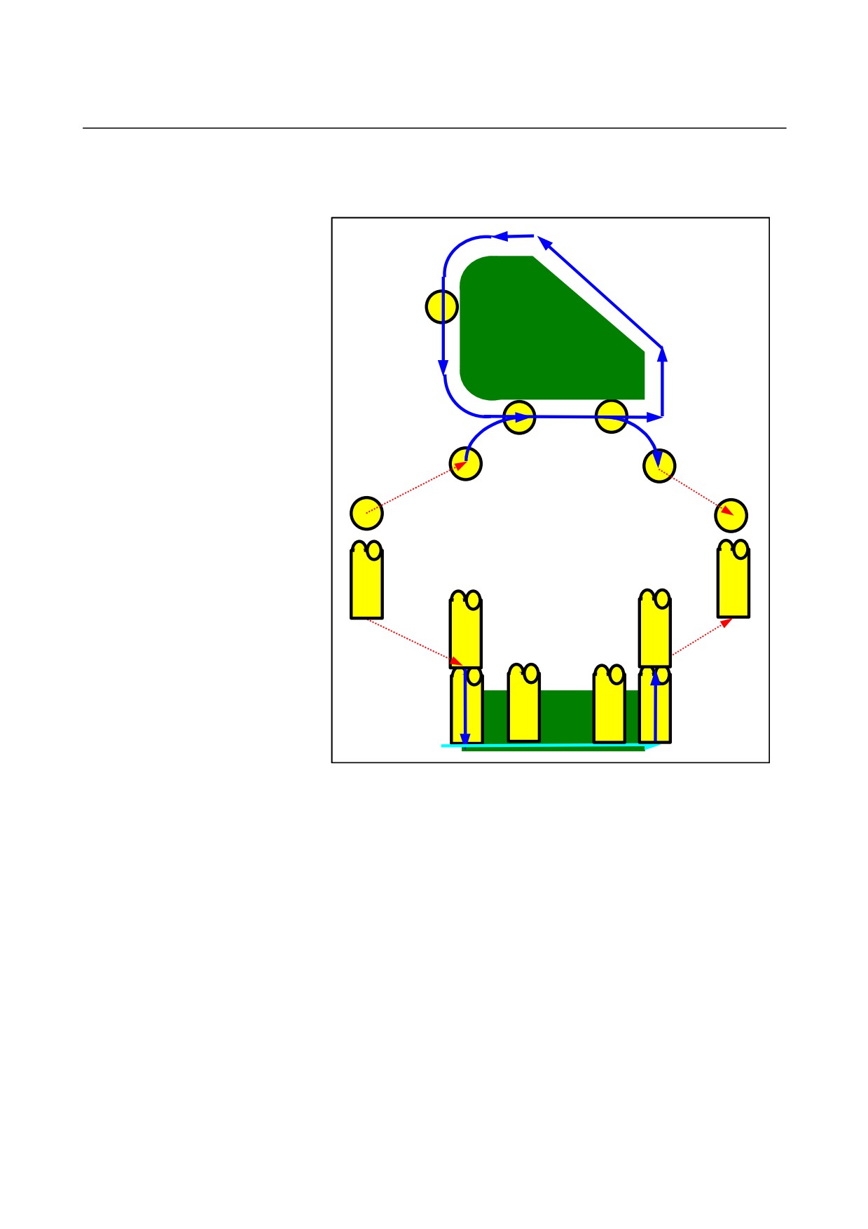
• Tool path
The side-face contour of the machining profile is finished.
The following tool path is created.
Approach
Retract
<1> The tool approaches a point above the approach start point.
<2> The tool moves to the bottom surface of the machining profile.
<3> The tool moves to cut along the side-face contour of the
machining profile.
In-feed machining is performed for the cutting allowance (Vt) in the
tool radius direction a specified number of finishing cycles.
<4> The tool retracts.
- 397 -
1.MILLING
CYCLE MACHINING TYPES
B-63874EN/05
- Approach
Cutting start point
Approach start point
Clearance Ct in the tool axis direction
Machining profile top
surface height
Ftm
Ft
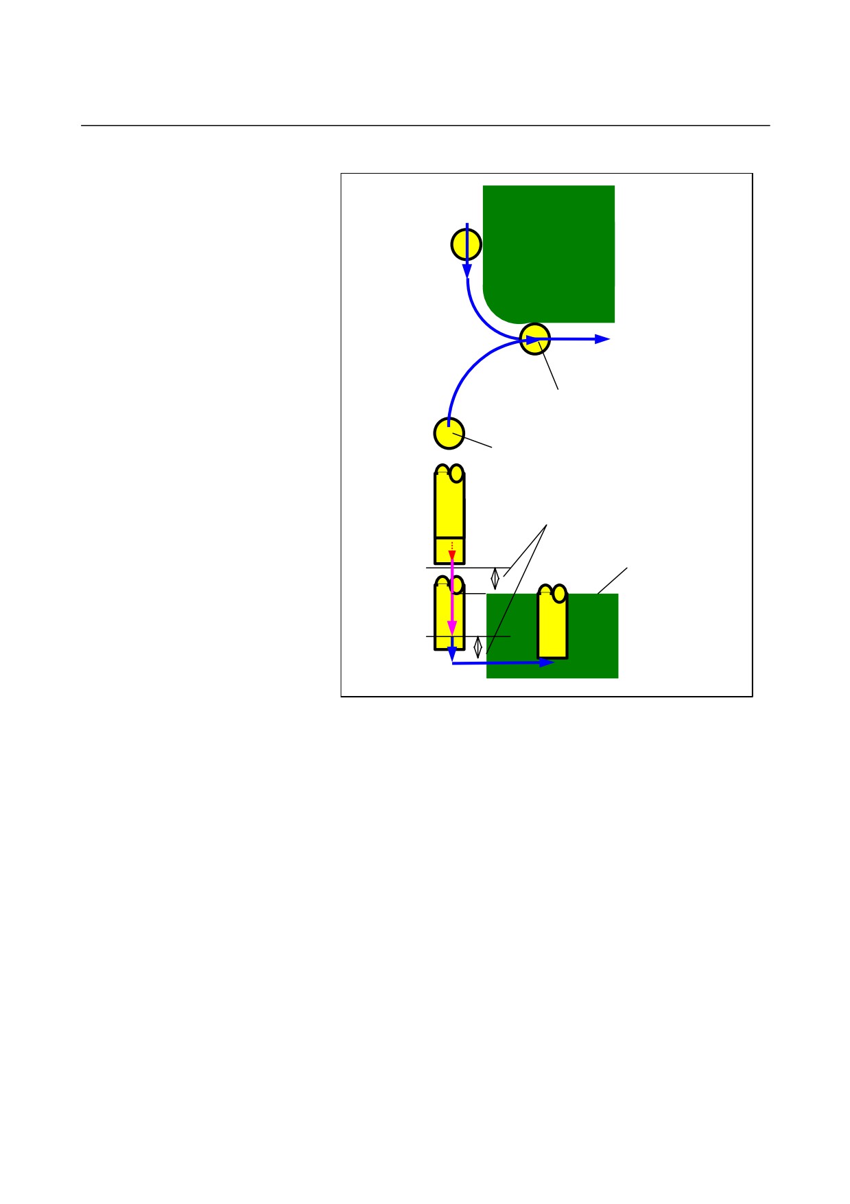
<1> The tool moves to the position "machining profile top surface
height
+ clearance
(Ct) in the tool axis direction" by rapid
traverse.
<2> The tool moves to the position "machining profile bottom surface
+ finishing allowance (Tt) in the tool axis direction + clearance
(Ct) in the tool axis direction" at the feedrate (Ftm) specified for
movement in the tool axis direction.
<3> The tool moves to the position "machining profile bottom surface
+ finishing allowance
(Tt) in the tool axis direction" at the
feedrate (Ft) specified for cutting in the machining profile.
<4> The tool approaches, in the tool radius direction, the in-feed
machining start point in the tool radius direction.
- 398 -
B-63874EN/05
CYCLE MACHINING TYPES
1.MILLING
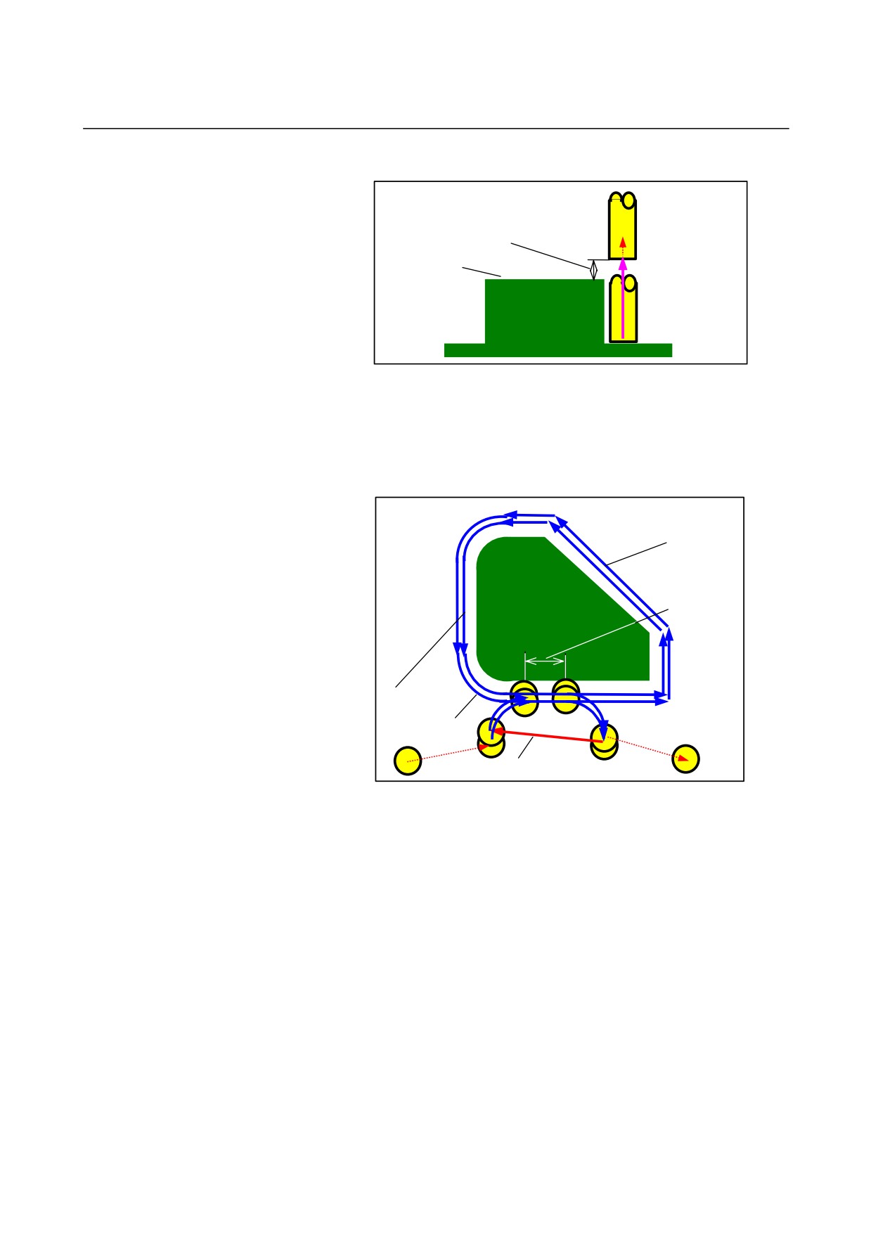
- Retraction
Clearance Ct in the tool axis direction
Machining profile top
surface height
Ftm
<1> The tool moves from the approach end point to the position
"machining profile top surface height + clearance (Ct) in the tool
axis direction" at the feedrate (Ftm) specified for movement in
the tool axis direction.
- In-feed machining in the tool radius direction
Feedrate Fr specified for cutting
in the tool radius direction
Overlapped length
Final finishing cycle
First finishing cycle
Feedrate Frm specified for movement
in the tool radius direction
<1> The tool approaches the cutting start point in the tool radius
direction at the feedrate (Fr) specified for cutting in the tool
radius direction.
<2> The tool moves to cut along the contour from the first in-feed
machining cycle start point to the first in-feed machining cycle
end point at the feedrate (Fr) specified for cutting in the tool
radius direction.
<3> The tool retracts from the cutting end point in the tool radius
direction at the feedrate (Fr) specified for cutting in the tool
radius direction.
<4> The tool approaches the next in-feed machining cycle start point,
using the specified [movement method for in-feed machining].
<5> Steps <2> to <4> are repeated as many times as the required
number of finishing cycles.
- 399 -
1.MILLING
CYCLE MACHINING TYPES
B-63874EN/05
Outer Wall Chamfer : G1063
Inner Wall Chamfer : G1067
Partial Chamfer : G1071
TOOL COND.
Data item
Meaning
K
TOOL SMALL DIAMETER
Diameter of the tip of a chamfering tool (positive
value)
NOTE
1 Tab ‘TOOL COND.’ is enabled when bit 0 (TLG) of
parameter No. 27002 = 1.
2 The operator ordinarily sets the above data on the
tab of ‘TOOL DATA’ in Tool Offset window.
Therefore, it is not necessary to display the tab
‘TOOL COND.’
CUT COND.
Data item
Meaning
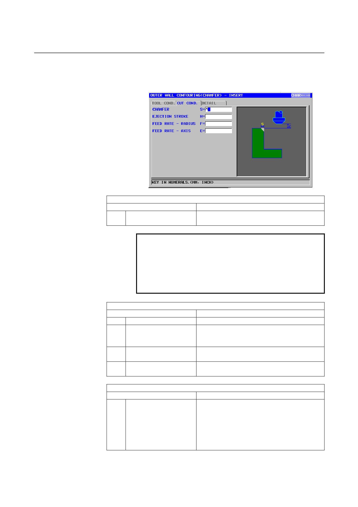
S
CHAMFER
Chamfer length (radius value, positive value)
H
EJECTION STROKE
Distance between the tip of a chamfering tool and
an actually cut position in the tool axis direction
(radius value, positive value)
F
FEED RATE- RADIUS
Feedrate applicable when cutting is performed in
the tool radius direction
E
FEED RATE- AXIS
Feedrate applicable when cutting is performed in
the tool axis direction
DETAIL
Data item
Meaning
W
UP CUT/DOWN CUT
[UP CUT]
: Performs machining in up-cut mode,
assuming that the tool is rotating
clockwise.
[DWNCUT] : Performs machining in down-cut
mode, assuming that the tool is
rotating clockwise.
(COPY)
- 400 -

B-63874EN/05
CYCLE MACHINING TYPES
1.MILLING
DETAIL
Data item
Meaning
C
CLEARANCE OF AXIS
Distance between the surface of a blank being
machined and a cutting start point (point R) in the
tool axis direction (radius value, positive value)
Remark) By referring to the parameter No.27009
(minimum clamp value), the system sets
the data as Initial value.
P
APPROACH TYPE
[ARC]
: Approaches a side face along an arc.
[TANGEN]: Approaches a side face along the
straight line tangent to the first figure
in side face cutting.
[VERTIC] : Approaches a side face along the
straight line normal to the first figure in
side face cutting.
(COPY)
R
APPROACH RAD./DIST.
Radius when [ARC] is specified.
Straight line length when [TANGEN] or [VERTIC]
is specified. (radius value, positive value)
Remark) By referring to the parameter No.27010
(minimum clamp value), the system sets
the data as Initial value.
A*
APPROACH ANGLE
Center angle of the arc when [ARC] is specified.
The default is 90 degrees. (positive value)
Remark) This data item is indicated only when
[ARC] is selected for APPROACH TYPE.
(COPY)
Q
ESCAPE TYPE
[ARC]
: Retracts from a side face along an
arc.
[TANGEN]: Retracts from a side face along the
straight line tangent to the last figure
in side face cutting.
[VERTIC] : Retracts from a side face along the
straight line normal to the last figure in
side face cutting.
(COPY)
X
ESCAPE RAD./DIST.
Radius when [ARC] is specified.
Straight line length when [TANGEN] or [VERTIC]
is specified. (radius value, positive value)
Remark) By referring to the parameter No.27010
(minimum clamp value), the system sets
the data as Initial value.
Y*
ESCAPE ANGLE
Center angle of the arc when [ARC] is specified.
The default is 90 degrees. (positive value)
Remark) This data item is indicated only when
[ARC] is selected for ESCAPE TYPE.
(COPY)
- 401 -