FANUC MANUAL GUIDE i. OPERATOR’S MANUAL - page 12
24.PROGRAM COORDINATE SYSTEM CHANGING FUNCTION AND TOOL OFFSET MEMORY CHANGING FUNCTION OPERATION
B-63874EN/05
24
PROGRAM COORDINATE SYSTEM
CHANGING FUNCTION AND TOOL
OFFSET MEMORY CHANGING
FUNCTION
Programming, machining simulation and input/output of data which
are fit for changing coordinate by
“Program Coordinate System
Changing Function” and “Tool Offset Memory Changing Function”
can be executed in MANUAL GUIDE i.
NOTE
1 About the details of these functions, refer to the
document of “FANUC Series 16 i /18 i /21 i -TB
Program Coordinate System Changing Function and
Tool Offset Memory Changing Function”
Specifications.
2 The Program Coordinate System Changing Functions
of MANUAL GUIDE i can be used under the following
case.
1) The axes, which are possible to reverse the
direction by the Program Coordinate System
Changing, must be Z-axis and Y-axis.
2) The right-handed coordinate system must be
still used after changing the program coordinate
system.
- 312 -
B-63874EN/05
OPERATION
24.PROGRAM COORDINATE SYSTEM CHANGING FUNCTION AND TOOL OFFSET MEMORY CHANGING FUNCTION
24.1 PROGRAM COORDINATE SYSTEM CHANGING
FUNCTION
In this paragraph, the way to select program coordinate during
operation, executing simulation and making arbitrary figures is
explained.
NOTE
1 The turning cycle option is essential to use this
function.
2 By setting the prameter No.14851#4=1, this
function becomes available
24.1.1 COORDINATE SYSTEM SELECTION COMMAND
The program coordinate system is selected by Process Start Block
G1992.
Insert Coordinate System Selection Command
<1> G1992 Block
When the cell is inserted on the first spindle side, the following
block is inserted.
(Please refer to the section of process list editing function about
cell.)
And when this block is executed, the program coordinate system
changes to the coordinate system-1.
G1992 S1 W1 (COMMENT) ;
When the cell is inserted on the second spindle side, the
following block is inserted. And when this block is executed,
the program coordinate system changes to the coordinate
system-2.
G1992 S2 W2 (COMMENT) ;
When the cell is copied or moved between the process list of the
different spindles,
‘W1’ or ‘W2’ are automatically changed
according to the spindle which the cell is moved to.
- 313 -
24.PROGRAM COORDINATE SYSTEM CHANGING FUNCTION AND TOOL OFFSET MEMORY CHANGING FUNCTION OPERATION
B-63874EN/05
Executing Program
When G1992 block is executed, the program coordinate system can be
changed by the followings.
<1> Change by M-code specified in the parameter
Please input M code number to parameter No.
27180 for
changing to the coordinate system-1 and to parameter No.
27181 for changing to the coordinate system-2.
When G1992 S** W** block is executed, the M-code which is
specified in the each parameter is outputted. Thus the program
coordinate system changes.
<2> Change by executing P-code macro sub-program specified in the
parameter
Please input P-code program number to parameter No. 27184
for changing to the coordinate system-1, and to parameter No.
27185 for changing to the coordinate system-2.
When G1992 S** W** block is executed, the P-code program
which is specified in the each parameter is outputted. Thus the
program coordinate system changes.
If both parameters the above <1> and <2> are specified, the P-code
program is called first. And next, the M-code is output.
- 314 -
B-63874EN/05
OPERATION
24.PROGRAM COORDINATE SYSTEM CHANGING FUNCTION AND TOOL OFFSET MEMORY CHANGING FUNCTION
24.1.2 COORDINATE OF ARBITRARY FIGURES (XZ, ZC, ZY PLANE)
On the following arbitrary figures entering window, the programming
figures are displayed according to the selected program coordinate
system.
<1> Arbitrary Figures for the XZ Plane
<2> Arbitrary Figures for the ZC Plane
<3> Arbitrary Figures for the ZY Plane
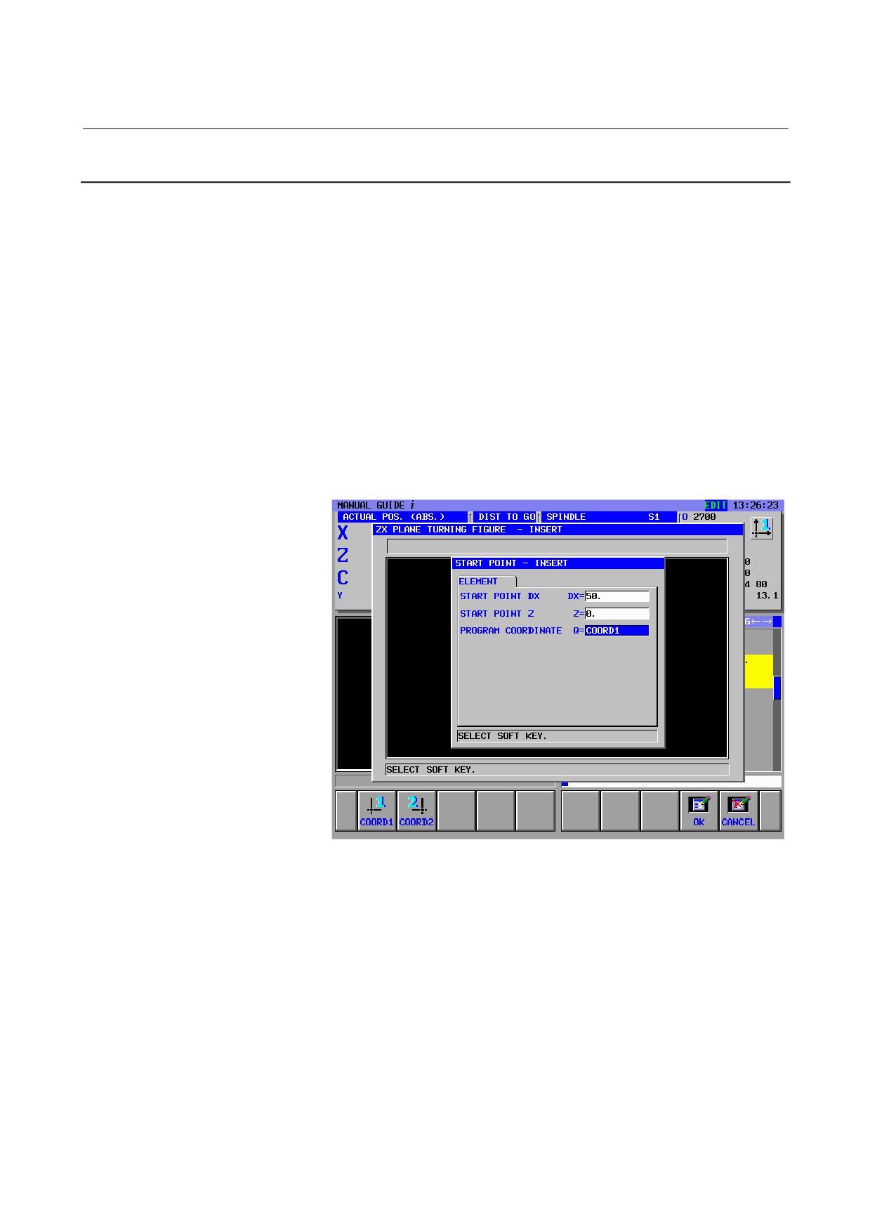
Select Display Coordinate System
The display of coordinate system can be selected on the entering
window for Start Point.
If “COORD1” is selected, the display of coordinate system changes to
the program coordinate system-1. And if “COORD2” is selected, the
display of coordinate system changes to the program coordinate
system-2.
Entering Window for Start Point
- 315 -
24.PROGRAM COORDINATE SYSTEM CHANGING FUNCTION AND TOOL OFFSET MEMORY CHANGING FUNCTION OPERATION
B-63874EN/05
24.1.3 MACHINING SIMULATION
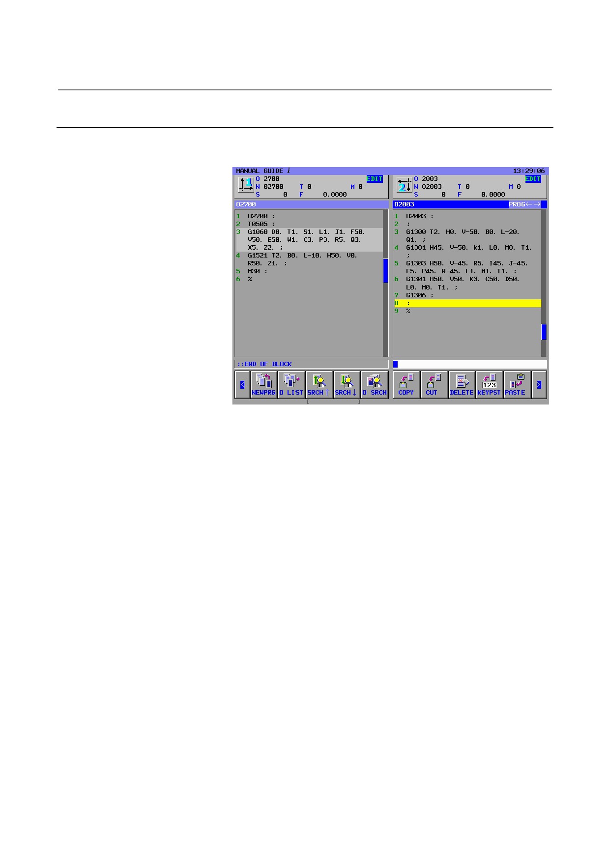
In the case of executing the machining simulation (Tool Path and
Animated), the program coordinate system is changed by the address
W1 and W2 of G1992 block.
NOTE
If the machining operation is finished at the status
of selecting the coordinate system-2 and the
machining operation is started again, the program
is executed on the coordinate system-2.
- 316 -
B-63874EN/05
OPERATION
24.PROGRAM COORDINATE SYSTEM CHANGING FUNCTION AND TOOL OFFSET MEMORY CHANGING FUNCTION
24.1.4 STATUS DIPLAY
The current program coordinate system displays in the status display
window by the icon.
The display icon, which is described the selected program coordinate
system, is specified by the parameters No.27188 and 27189.
- 317 -
24.PROGRAM COORDINATE SYSTEM CHANGING FUNCTION AND TOOL OFFSET MEMORY CHANGING FUNCTION OPERATION
B-63874EN/05
24.2 TOOL OFFSET MEMORY CHANGING FUNCTION
Tool offset, tool data and work shift for program coordinate system 1
and 2 can be inputted separately.
NOTE
The following functions can be used when the Tool
Offset Memory Changing Function is enabled.
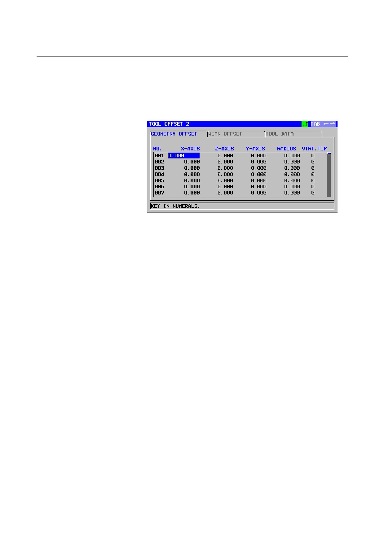
24.2.1 TOOL OFFSET DATA WINDOW
It is possible to set the tool offset data for each program coordinate
system 1 and 2.
Select Coordinate System
The display of the data for each coordinate system changes as
following by the parameter GCC(No.14851#6).
<1> In the case parameter GCC is 0
It is possible to change the display of the tool offset data for each
coordinate system by pressing the [1←→2] soft-key.
ACTPOS
MEASUR
+INPUT
INP.C.
CHCURS
1←→2
NO.SRH
CLOSE
<2> In the case parameter GCC is 1
The display of the tool offset data for each coordinate system changes
according to DO-signal(F0347#GCO) dynamically.
- 318 -
B-63874EN/05
OPERATION
24.PROGRAM COORDINATE SYSTEM CHANGING FUNCTION AND TOOL OFFSET MEMORY CHANGING FUNCTION
Display Selected Coordinate System
The symbol for the selected coordinate system is displayed in the title
of the window. The symbol is displayed according to the parameters
No.27188 and No.27189.
When the coordinate system-2 is selected.
Setting of Tool Data
When the Tool Offset Memory Changing Function is effective, the
maximum tool number which is possible to set to the tool data base is
as follows.
for Program Coordinate System-1 : 150
for Program Coordinate System-2 : 150
The tool data for each program coordinate system are possible to input
from and output to the memory card.
- 319 -

24.PROGRAM COORDINATE SYSTEM CHANGING FUNCTION AND TOOL OFFSET MEMORY CHANGING FUNCTION OPERATION
B-63874EN/05
24.2.2 WORKPIECE SHIFT OFFSET DATA WINDOW
It is possible to set the workpiece shift offset data for each program
coordinate system 1 and 2.
Select Coordinate System
The display of the data for each coordinate system changes as follows
by the parameter GCC(No.14851#6).
<1> In the case parameter GCC is 0
It is possible to change the display of workpiece shift data for each
coordinate system by pressing the [1←→2] soft-key.
ACTPOS
MEASUR
+INPUT
CHCURS
1←→2
NO.SRH
CLOSE
<2> In the case parameter GCC is 1
The display of the data for each coordinate system changes according
to DO-signal(F0347#GCO) dynamically.
- 320 -
B-63874EN/05
OPERATION
24.PROGRAM COORDINATE SYSTEM CHANGING FUNCTION AND TOOL OFFSET MEMORY CHANGING FUNCTION
24.3 SET-UP GUIDANCE FUNCTIONS
There is not improvement in Set-Up Guidance Function.
So, even if the Tool Offset Memory Changing Function is effective,
the exclusive measurement condition data and the calibration data for
each program coordinate system are not provided. So it had better to
distinguish these data between for the measurement in the program
coordinate system-1 and 2.
24.3.1 MANUAL MEASUREMENT
When Tool Measurement or Measure is executed, the measurement
data is set to the tool offset data of which program coordinate system
is selected.
24.3.2 MEASUREMENT CYCLE
When Tool Measurement or Measure is executed, the measurement
data is set to the tool offset data of which program coordinate system
is selected.
24.3.3 MEASUREMENT RESULT DISPLAY SCREEN
In the case that the measurement data is set to the tool offset data,
whether the offset data for program coordinate system-1 or for
program coordinate system-2 is described after ‘G’ or ‘W’ character
as follows.
(Example)
Z 0.973 Z 0.000
T-Z10-G1
-0.973
Geometry offset data for program coordinate system-1 was set.
Z 0.973 Z 0.000
T-Z10-G2
-0.973
Geometry offset data for program coordinate system-2 was set.
Z 0.973 Z 0.000
T-Z10-W1
-0.973
Wear offset data for program coordinate system-1 was set.
Z 0.973 Z 0.000
T-Z10-W2
-0.973
Wear offset data for program coordinate system- 2 was set.
- 321 -
24.PROGRAM COORDINATE SYSTEM CHANGING FUNCTION AND TOOL OFFSET MEMORY CHANGING FUNCTION OPERATION
B-63874EN/05
24.4 CAUTIONS
If the machining operation is finished at the status of selecting the
coordinate system-2 and the machining operation is started again, the
program is executed on the coordinate system-2.
So be sure to insert the coordinate system selection commands to
the top of the machining program to avoid executing machining
under the wrong coordinate system.
There are the following restrictions.
•
The Program Coordinate System Changing Functions and the
Tool Offset Memory Changing Functions can not be used on
turnin mode of compound machine.
- 322 -
III. CYCLE MACHINING TYPES
B-63874EN/05
CYCLE MACHINING TYPES
1.MILLING
1
MILLING
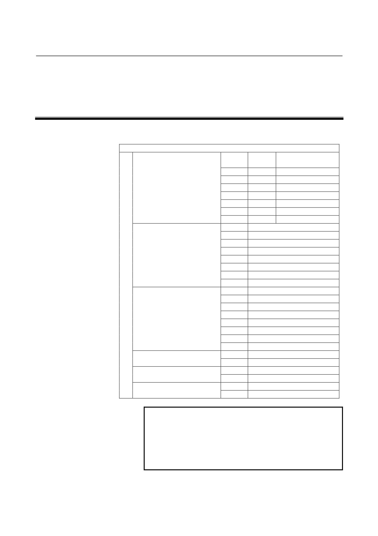
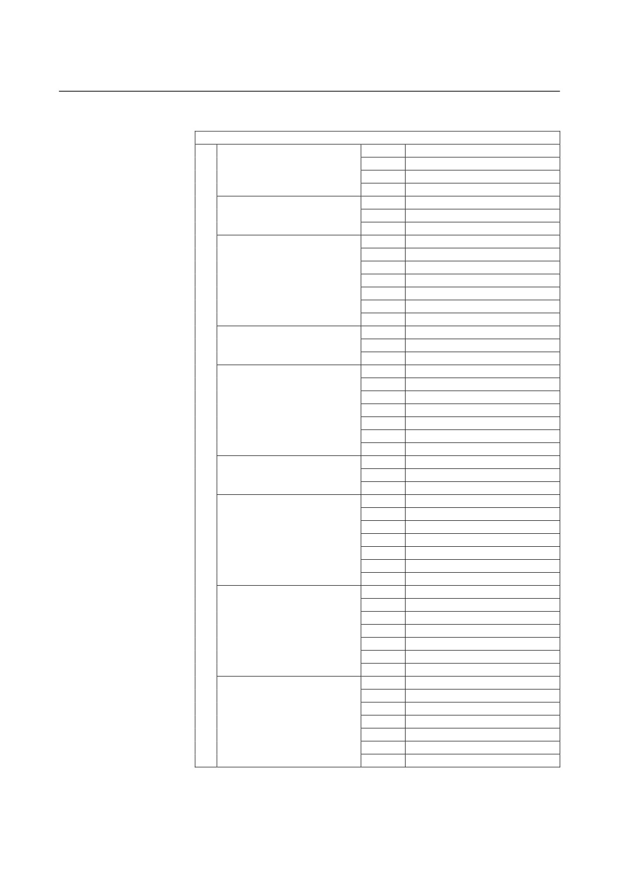
MANUAL GUIDE i supports the following types of milling.
Hole machining (with the tool rotated)
Machining type block
Milling
Turning
(Note)
(Note)
G1000
G1110
Center drilling
G1001
G1111
Drilling
G1002
G1112
Tapping
G1003
G1113
Reaming
G1004
G1114
Boring
G1005
-
Fine boring
G1006
-
Back boring
G1210
Random points
G1211
Linear points (same interval)
G1212
Linear points (different interval)
G1213
Grid points
Hole position block (XY plane)
G1214
Rectangle points
G1215
Circle points
G1216
Arc points (same interval)
G1217
Arc points (different interval)
G1310
Random points
G1311
Linear points (same interval)
G1312
Linear points (different interval)
G1313
Grid points
Hole position block (YZ plane)
G1314
Rectangle points
G1315
Circle points
G1316
Arc points (same interval)
G1317
Arc points (different interval)
Hole position block (XC plane,
G1572
Circle points
end face)
G1573
Random points
Hole position block (ZC plane,
G1672
Circle points
cylindrical surface)
G1673
Random points
Hole position block (XA plane,
G1772
Circle points
cylindrical surface)
G1773
Random points
NOTE
Hole Machining with the tool rotated has 2 type for
Milling machine and Turning machine (Lathe).
Therefore, please set the parameter No.27000 #1
in order to use suitable one for your machine.
No.27000#1=0 : For Milling machine
No.27000#1=1 : For Lathe
- 325 -
1.MILLING
CYCLE MACHINING TYPES
B-63874EN/05
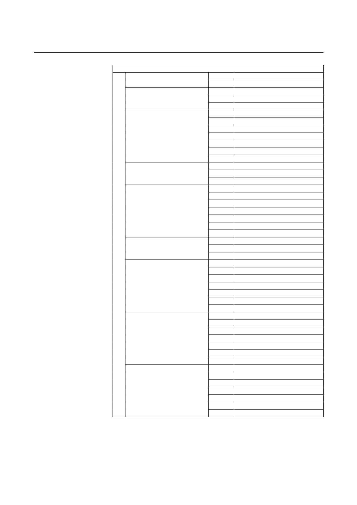
Facing
G1020
Roughing
Machining type block
G1021
Finishing
G1220
Rectangle
Fixed-figure block (XY plane)
G1221
Circle
G1222
Track
G1200
Start point
G1201
Straight line
G1202
Arc (CW)
Arbitrary-figure block
G1203
Arc (CCW)
(XY plane)
G1204
Chamfering
G1205
Corner rounding
G1206
End
G1320
Rectangle
Fixed-figure block
G1321
Circle
(YZ plane)
G1322
Track
G1300
Start point
G1301
Straight line
G1302
Arc (CW)
Arbitrary-figure block
G1303
Arc (CCW)
(YZ plane)
G1304
Chamfering
G1305
Corner rounding
G1306
End
G1520
Rectangle
Fixed figure block (XC plane,
G1521
Circle
end face)
G1522
Track
G1500
Start point
G1501
Straight line
G1502
Arc (CW)
Arbitrary-figure block (XC plane,
G1503
Arc (CCW)
end face)
G1504
Chamfering
G1505
Corner rounding
G1506
End
G1600
Start point
G1601
Straight line
G1602
Arc (CW)
Arbitrary-figure block (ZC plane,
G1603
Arc (CCW)
cylindrical surface)
G1604
Chamfering
G1605
Corner rounding
G1606
End
G1700
Start point
G1701
Straight line
G1702
Arc (CW)
Arbitrary-figure block (XA plane,
G1703
Arc (CCW)
cylindrical surface)
G1704
Chamfering
G1705
Corner rounding
G1706
End
- 326 -
B-63874EN/05
CYCLE MACHINING TYPES
1.MILLING
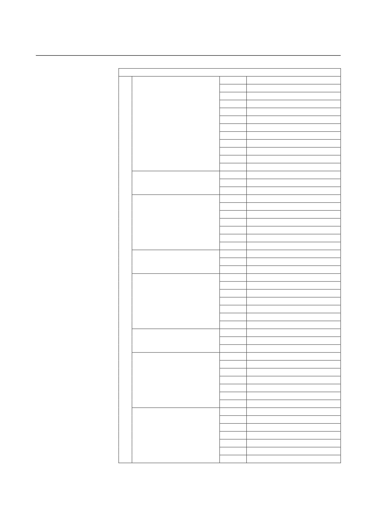
Contouring
G1060
Outer Wall Roughing
G1061
Outer Wall Bottom finishing
G1062
Outer Wall Side finishing
G1063
Outer Wall Chamfering
G1064
Inner Wall Roughing
G1065
Inner Wall Bottom finishing
Machining type block
G1066
Inner Wall Side finishing
G1067
Inner Wall Chamfering
G1068
Partial Roughing
G1069
Partial Bottom finishing
G1070
Partial Side finishing
G1071
Partial Chamfering
G1220
Rectangle
Fixed-figure block
G1221
Circle
(XY plane)
G1222
Track
G1200
Start point
G1201
Straight line
G1202
Arc (CW)
Arbitrary-figure block
G1203
Arc (CCW)
(XY plane)
G1204
Chamfering
G1205
Corner rounding
G1206
End
G1320
Rectangle
Fixed-figure block
G1321
Circle
(YZ plane)
G1322
Track
G1300
Start point
G1301
Straight line
G1302
Arc (CW)
Arbitrary-figure block
G1303
Arc (CCW)
(YZ plane)
G1304
Chamfering
G1305
Corner rounding
G1306
End
G1520
Rectangle
Fixed-figure block (XC plane,
G1521
Circle
end face)
G1522
Track
G1500
Start point
G1501
Straight line
G1502
Arc (CW)
Arbitrary-figure block (XC plane,
G1503
Arc (CCW)
end face)
G1504
Chamfering
G1505
Corner rounding
G1506
End
G1600
Start point
G1601
Straight line
G1602
Arc (CW)
Arbitrary-figure block (ZC plane,
G1603
Arc (CCW)
cylindrical surface)
G1604
Chamfering
G1605
Corner rounding
G1606
End
- 327 -
1.MILLING
CYCLE MACHINING TYPES
B-63874EN/05
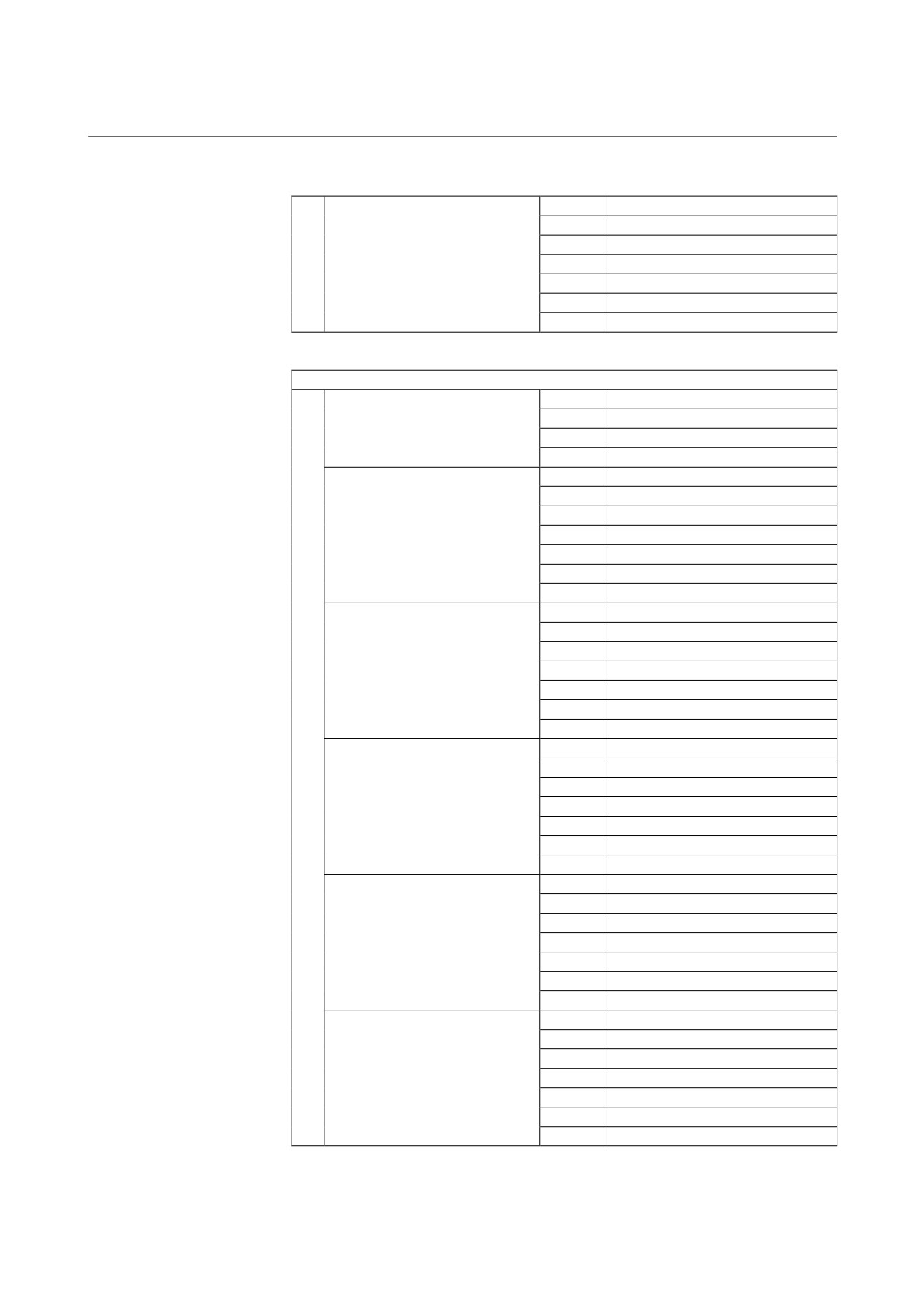
G1700
Start point
G1701
Straight line
G1702
Arc (CW)
Arbitrary-figure block (XA plane,
G1703
Arc (CCW)
cylindrical surface)
G1704
Chamfering
G1705
Corner rounding
G1706
End
Emboss machining
G1080
Roughing
G1081
Bottom finishing
Machining type block
G1082
Side finishing
G1083
Chamfering
G1200
Start point
G1201
Straight line
G1202
Arc (CW)
Arbitrary-figure block
G1203
Arc (CCW)
(XY plane)
G1204
Chamfering
G1205
Corner rounding
G1206
End
G1300
Start point
G1301
Straight line
G1302
Arc (CW)
Arbitrary-figure block
G1303
Arc (CCW)
(YZ plane)
G1304
Chamfering
G1305
Corner rounding
G1306
End
G1500
Start point
G1501
Straight line
G1502
Arc (CW)
Arbitrary-figure block (XC plane,
G1503
Arc (CCW)
end face)
G1504
Chamfering
G1505
Corner rounding
G1506
End
G1600
Start point
G1601
Straight line
G1602
Arc (CW)
Arbitrary-figure block (ZC plane,
G1603
Arc (CCW)
cylindrical surface)
G1604
Chamfering
G1605
Corner rounding
G1606
End
G1700
Start point
G1701
Straight line
G1702
Arc (CW)
Arbitrary-figure block (XA plane,
G1703
Arc (CCW)
cylindrical surface)
G1704
Chamfering
G1705
Corner rounding
G1706
End
- 328 -
B-63874EN/05
CYCLE MACHINING TYPES
1.MILLING
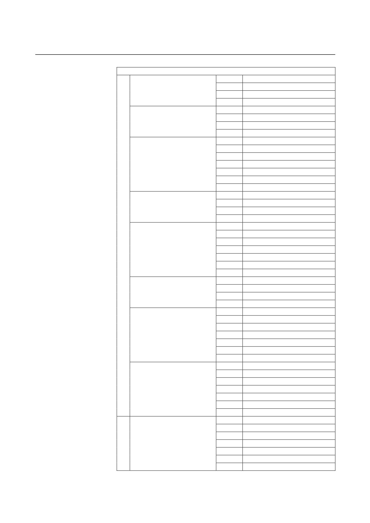
Pocketing
G1040
Roughing
G1041
Bottom finishing
Machining type block
G1042
Side finishing
G1043
Chamfering
G1220
Rectangle
Fixed-figure block
G1221
Circle
(XY plane)
G1222
Track
G1200
Start point
G1201
Straight line
G1202
Arc (CW)
Arbitrary-figure block
G1203
Arc (CCW)
(XY plane)
G1204
Chamfering
G1205
Corner rounding
G1206
End
G1320
Rectangle
Fixed-figure block
G1321
Circle
(YZ plane)
G1322
Track
G1300
Start point
G1301
Straight line
G1302
Arc (CW)
Arbitrary-figure block
G1303
Arc (CCW)
(YZ plane)
G1304
Chamfering
G1305
Corner rounding
G1306
End
G1520
Rectangle
Fixed-figure block (XC plane,
G1521
Circle
end face)
G1522
Track
G1500
Start point
G1501
Straight line
G1502
Arc (CW)
Arbitrary-figure block (XC plane,
G1503
Arc (CCW)
end face)
G1504
Chamfering
G1505
Corner rounding
G1506
End
G1600
Start point
G1601
Straight line
G1602
Arc (CW)
Arbitrary-figure block (ZC plane,
G1603
Arc (CCW)
cylindrical surface)
G1604
Chamfering
G1605
Corner rounding
G1606
End
G1700
Start point
G1701
Straight line
G1702
Arc (CW)
Arbitrary-figure block (XA plane,
G1703
Arc (CCW)
cylindrical surface)
G1704
Chamfering
G1705
Corner rounding
G1706
End
- 329 -
1.MILLING
CYCLE MACHINING TYPES
B-63874EN/05
Grooving
G1050
Roughing
G1051
Bottom finishing
Machining process block
G1052
Side finishing
G1053
Chamfering
G1220
Rectangle
Fixed-figure block
G1221
Circle
(XY plane)
G1222
Track
G1223
Radial groove
G1200
Start point
G1201
Straight line
G1202
Arc (CW)
Arbitrary-figure block
G1203
Arc (CCW)
(XY plane)
G1204
Chamfering
G1205
Corner rounding
G1206
End
G1320
Rectangle
Fixed-figure block
G1321
Circle
(YZ plane)
G1322
Track
G1323
Radial groove
G1300
Start point
G1301
Straight line
G1302
Arc (CW)
Arbitrary-figure block
G1303
Arc (CCW)
(YZ plane)
G1304
Chamfering
G1305
Corner rounding
G1306
End
G1520
Rectangle
Fixed-figure block (XC plane,
G1521
Circle
end face)
G1522
Track
G1523
Radial groove
G1500
Start point
G1501
Straight line
G1502
Arc (CW)
Arbitrary-figure block (XC plane,
G1503
Arc (CCW)
end face)
G1504
Chamfering
G1505
Corner rounding
G1506
End
G1600
Start point
G1601
Straight line
G1602
Arc (CW)
Arbitrary-figure block (ZC plane,
G1603
Arc (CCW)
cylindrical surface)
G1604
Chamfering
G1605
Corner rounding
G1606
End
G1700
Start point
G1701
Straight line
G1702
Arc (CW)
Arbitrary-figure block (XA plane,
G1703
Arc (CCW)
cylindrical surface)
G1704
Chamfering
G1705
Corner rounding
G1706
End
- 330 -

B-63874EN/05
CYCLE MACHINING TYPES
1.MILLING
C axis grooving
Machining process block
G1056
C axis grooving
Fixed-figure block (XC plane,
G1570
C axis groove
end face)
G1571
X axis groove
Fixed-figure block (ZC plane,
G1670
C axis groove
cylindrical surface)
G1671
Z axis groove
A axis grooving
Fixed-figure block (XA plane,
G1770
A axis groove
cylindrical surface)
G1771
X axis groove
- 331 -
1.MILLING
CYCLE MACHINING TYPES
B-63874EN/05
NOTE
1
MANUAL GUIDE i supports three types of hole
machining, that is, hole machining by milling, hole
machining by turning (with the tool rotated), and
hole machining by turning (with the workpiece
rotated).
On the CNC for milling, only hole machining by
milling is usable. On the CNC for lathe turning, hole
machining by turning (with the tool rotated) and
hole machining by turning (with the workpiece
rotated) are usable.
On the CNC for complex machining, all types of
machining are usable, and what machining type to
use can be selected using parameters.
Refer to manuals from respective machine tool
builders for explanations about what type is
actually usable.
2
When MANUAL GUIDE i is used to enter cycle
machining data, combinations of a machining type
block and a figure block must be entered in
succession for all machining types except hole
machining by turning.
More than one figure block can be entered for one
machining type block.
For arbitrary figures, however, more than one set of
arbitrary figures can be entered if one set is
assumed to consist of up to 90 figures enclosed
between start and end points.
3
A data item whose address is indicated with [*] in
the following tables is automatically set with a
typical value unless a value is entered for it. You
need to enter no data if you accept the typical
value.
4
On the screen, [*] is displayed in the right end of
the data item.
5
In some of the input data items, the system sets
the last inputted data as an initial data. As to these
input data items, the mark of “(COPY)” was
described.
6
In the input data item of “APROCH MOTION”,
when the machine is 2 axes of Maximum
simultaneously controlled axes, please sure not to
specify the [3 AXES] soft-key.
(If [3 AXES] is specified, the alarm 15 occurred
during execution of Cycles.)
- 332 -
B-63874EN/05
CYCLE MACHINING TYPES
1.MILLING
NOTE
7 In the input data item of “CUT ANGLE” of
Pocketing Rough (G1040) and Bottom Finish
(G1041), when the machine is 2 axes of Maximum
simultaneously controlled axes, please sure not to
set the data.
(If the data is set, the alarm 15 occurred during
execution of Cycles.)
8 The motions go back to the start point where the
machining cycle started after completing the all
cycle motions.
(It is possible not to go back to the start point when
the parameter No. 27002#7 is set to 1.)
9 Cycle machining cannot be performed in any of
control modes of the high-speed and high-precision
functions (commands for advanced preview
control, AI advanced preview control, AI contour
control, AI nano contour control, high-precision
contour control, AI high-precision contour control,
and AI nano high-precision contour control). To
perform cycle machining, control mode must be
canceled.
10 On the CNC for lathe turning with G-code system B
or C, when cycle machining is specified, G90 must
be specified in advance to make a switchover to
the absolute coordinate system. For hole
machining by turning (with the tool rotated), G98
(initial level return) or G99 (R position level return)
must be specified in advance.
11 On the CNC for milling, when cycle machining is
specified, a switchover to G90 (absolute command)
occurs internally. Therefore, G91 must be specified
if incremental commands are used after cycle
machining.
- 333 -
1.MILLING
CYCLE MACHINING TYPES
B-63874EN/05
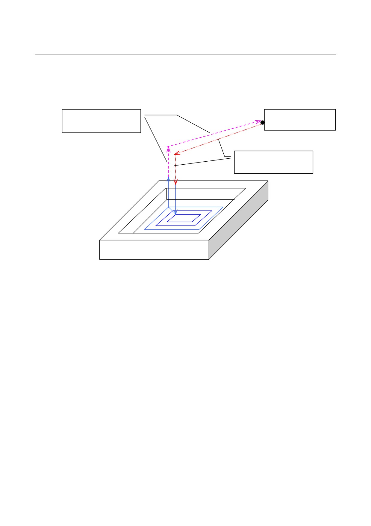
Remarks) Cycle retract motions
In case of No.27002#7=0, Retracting motions indicated as
broken lines in the following drawing will be outputted. The
order of motion axis will be opposite to the approached motions
Retracting motions of a
Position where the
machining cycle
machining cycle started
Approaching motions of a
machining cycle
In case of carrying out plural figures machining by one G4 digit cycle,
such like drilling or C-axis grooving, this retracting motions will be
available at the last figure machining.
- 334 -
B-63874EN/05
CYCLE MACHINING TYPES
1.MILLING
1.1
HOLE MACHINING BY MILLING
1.1.1
Hole Machining Type Block
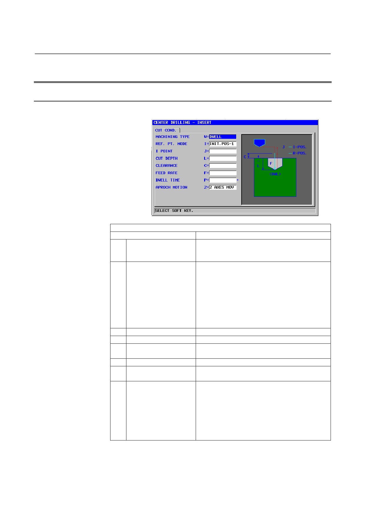
Center Drilling: G1000
CUT COND.
Data item
Meaning
W
MACHINING TYPE
[NORMAL] : No dwelling is performed.
(initial value)
[DWELL]
: Dwelling is performed.
I
REF. PT. MODE
[INIT-1]: An R position return is made in moving
between holes. Finally, a return is made to
the I point. (initial value)
[INIT-2]: All movements between holes, including
the last return, are made as an I point
return.
[REF.] : All movements between holes, including
the last return, are made as an R position
return.
J
I POINT
Coordinate of the I point
(COPY)
L
CUT DEPTH
Cut depth (radius value, negative value)
C
CLEARANCE
Distance between the workpiece surface and R
position (radius value, positive value)
(COPY)
F
FEED RATE
Cutting feedrate (positive value)
(COPY)
P*
DWELL TIME
Dwell time at the hole bottom. If omitted, 0 is
assumed. (units of seconds, positive value) (COPY)
Z
APROCH MOTION
[2 AXES] : When moving from the current position
to the machining start point, the tool first
moves in the machining plane in two-axis
synchronous operation and then moves
along the tool axis. (initial value)
[3 AXES] : The tool moves from the current position
to the machining start point in three-axis
synchronous operation.
- 335 -
1.MILLING
CYCLE MACHINING TYPES
B-63874EN/05
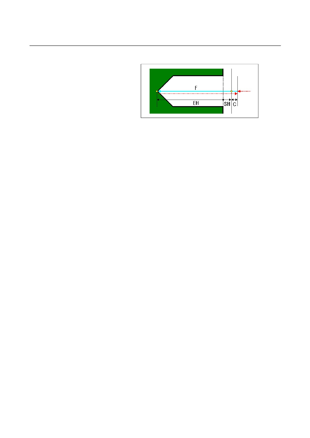
• Tool path
<1> Move the tool to the position "cutting start position + clearance
(C)" in rapid traverse.
<2> Move the tool to the cutting end position at the cutting feedrate
(F).
<3> Move the tool to the position "cutting start position + clearance
(C)" in rapid traverse.
- 336 -
B-63874EN/05
CYCLE MACHINING TYPES
1.MILLING
Drilling: G1001
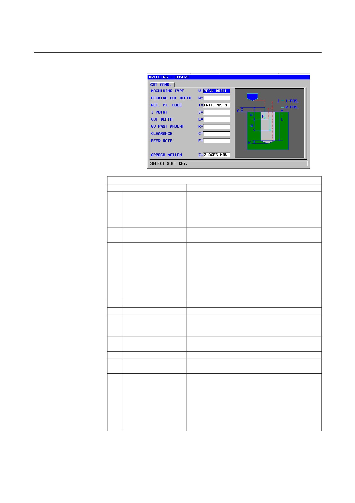
CUT COND.
Data item
Meaning
W
MACHINING TYPE
[NORMAL] : One cut with no dwelling performed
(initial value)
[DWELL]
: One cut with dwelling performed
[PECK]
: Peck drilling
(Note 1)
[H SPED]
: High-speed peck drilling
(Note 2)
Q
PECKING CUT DEPTH
Depth of cut made by one cut (radius value, positive
value)
(COPY)
I
REF. PT. MODE
[INIT-1] : An R position return is made in moving
between holes. Finally, a return is made to
the I point. (initial value)
[INIT-2] : All movements between holes, including the
last return, are made as an I point return.
[REF.]
: All movements between holes, including the
last return, are made as an R position
return.
J
I POINT
Coordinate of the I point
(COPY)
L
CUT DEPTH
Cut depth (radius value, negative value)
K
GO PAST AMOUNT
Length of the incomplete hole portion at the tool tip. If
omitted, 0 is assumed. (Radius value, positive value)
(COPY)
C
CLEARANCE
Distance between the workpiece surface and R
position (radius value, positive value)
(COPY)
F
FEED RATE
Cutting feedrate (positive value)
(COPY)
P*
DWELL TIME
Dwell time at the hole bottom. If omitted, 0 is
assumed. (units of seconds, positive value)
(COPY)
Z
APROCH MOTION
[2 AXES] : When moving from the current position to
the machining start point, the tool first
moves in the machining plane in two-axis
synchronous operation and then moves
along the tool axis. (initial value)
[3 AXES] : The tool moves from the current position
to the machining start point in three-axis
synchronous operation.
- 337 -
1.MILLING
CYCLE MACHINING TYPES
B-63874EN/05
NOTE
1 In the case of ‘MACHINING TYPE’ = ‘PECK’, the
system refers to the parameter No.5115 as the
return amount. Therefore, please set No.5115 to
suitable value before machining.
2 In the case of ‘MACHINING TYPE’ = ‘H SPED’, the
system refers to the parameter No.5114 as the
return amount. Therefore, please set No.5114 to
suitable value before machining.
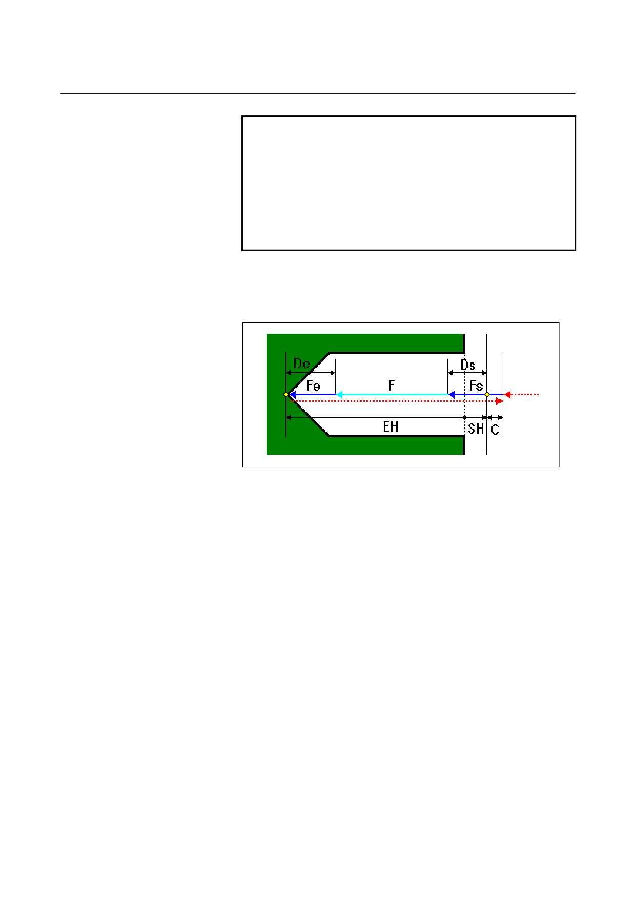
• Tool path
A drilling tool path can be selected from the following:
- [NORMAL]/[DWELL]
<1> Move the tool to the position "cutting start position + clearance
(C)" in rapid traverse.
<2> Move the tool to the cutting end position at the cutting feedrate
(F).
<3> Move the tool to the position "cutting start position + clearance
(C)" in rapid traverse.
- 338 -
B-63874EN/05
CYCLE MACHINING TYPES
1.MILLING
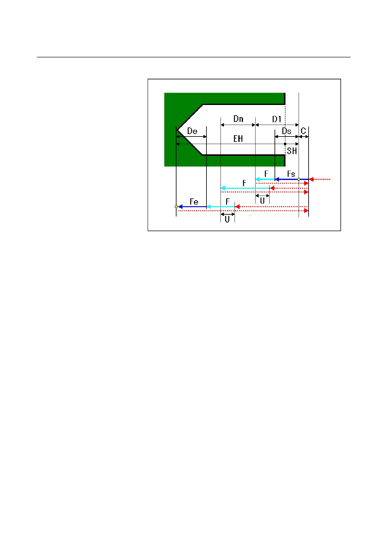
- [PECK]
<1> Move the tool to the position "cutting start position + clearance
(C)" in rapid traverse.
<2> Move the tool to the position "cutting start position - primary cut
depth (D1)" at the cutting feedrate (F).
<3> Move the tool to the position "cutting start position + clearance
(C)" in rapid traverse.
<4> Move the tool to the position "previous cutting end position +
return clearance (U)" in rapid traverse.
<5> Move the tool to the position "previous cutting end position -
compensation cut depth (Dn)" at the cutting feedrate (F).
<6> Repeat steps <3> to <5> until the last cutting end position is
reached.
<7> Move the tool to the position "cutting start position + clearance
(C)" in rapid traverse.
- 339 -
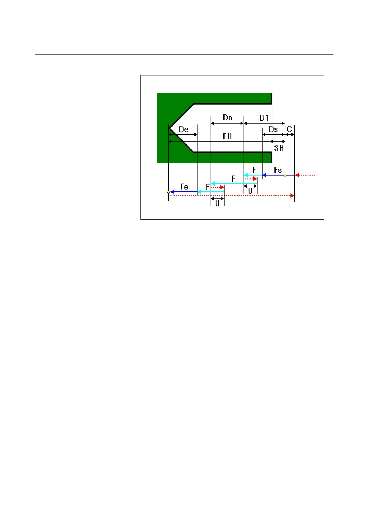
1.MILLING
CYCLE MACHINING TYPES
B-63874EN/05
- [H SPED]
<1> Move the tool to the position "cutting start position + clearance
(C)" in rapid traverse.
<2> Move the tool to the position "cutting start position - primary cut
depth (D1)" at the cutting feedrate (F).
<3> Move the tool to the position "current position + return clearance
(U)" in rapid traverse.
<4> Move the tool to cut to the position "previous cutting end
position - compensation cut depth (Dn)" at the cutting feedrate
(F).
<5> Repeat steps <3> and <4> until the cutting end position is
reached.
<6> Move the tool to the position "cutting start position + clearance
(C)" in rapid traverse.
- 340 -
B-63874EN/05
CYCLE MACHINING TYPES
1.MILLING
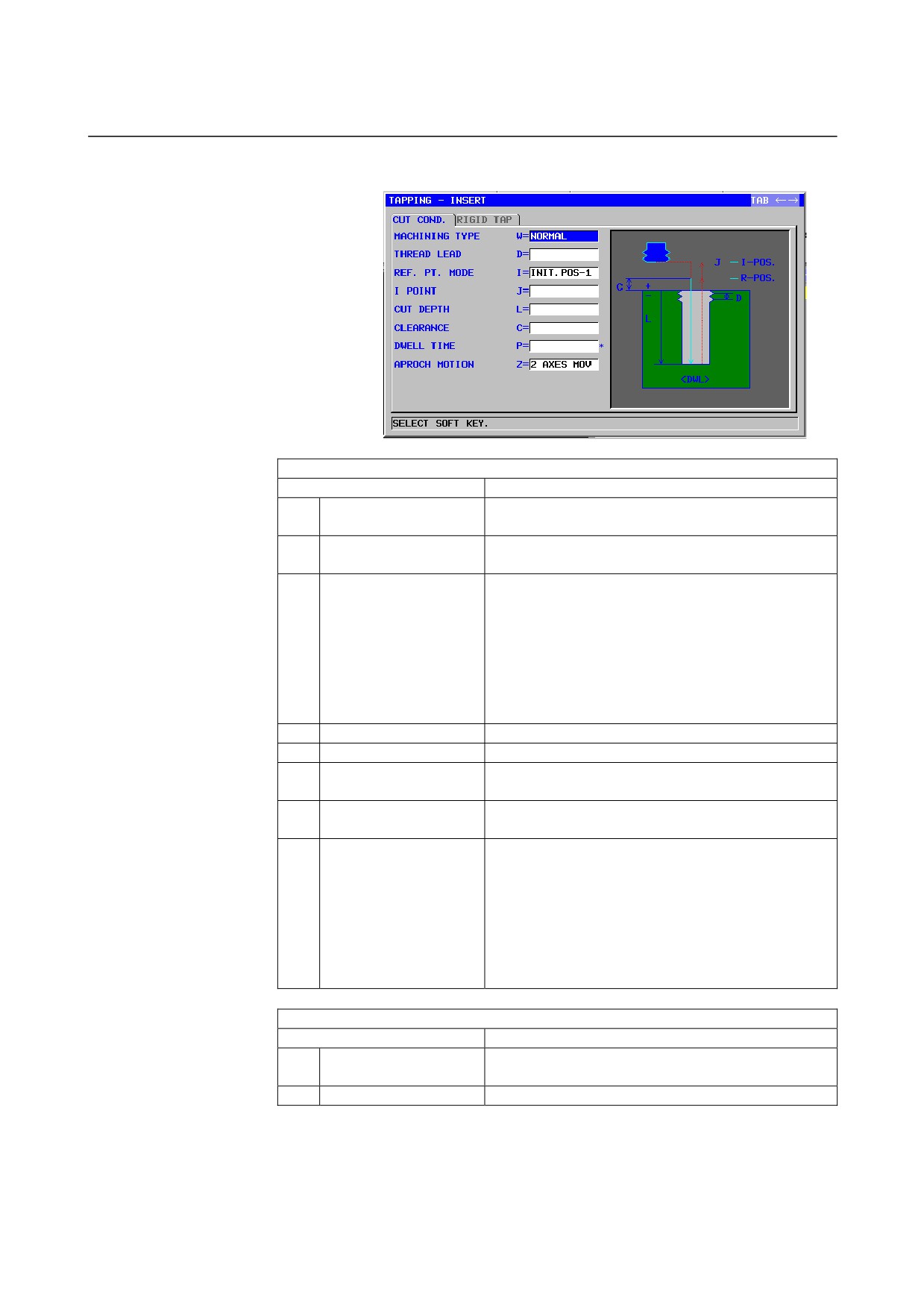
Tapping: G1002
CUT COND.
Data item
Meaning
W
MACHINING TYPE
[NORMAL] : CW tapping
(initial value)
[REVERS] : CCW tapping
D
THREAD LEAD
Tapping tool lead (radius value, positive value)
(COPY)
I
REF. PT. MODE
[INIT-1] : An R position return is made in moving
between holes. Finally, a return is made to
the I point. (initial value)
[INIT-2] : All movements between holes, including the
last return, are made as an I point return.
[REF.]
: All movements between holes, including the
last return, are made as an R position
return.
J
I POINT
Coordinate of the I point
(COPY)
L
CUT DEPTH
Cut depth (radius value, negative value)
C
CLEARANCE
Distance between the workpiece surface and R
position (radius value, positive value)
(COPY)
P*
DWELL TIME
Dwell time at the hole bottom. If omitted, 0 is
assumed. (units of seconds, positive value)
(COPY)
Z
APROCH MOTION
[2 AXES] : When moving from the current position to
the machining start point, the tool first
moves in the machining plane in two-axis
synchronous operation and then moves
along the tool axis. (initial value)
[3 AXES] : The tool moves from the current position
to the machining start point in three-axis
synchronous operation.
RIGID TAP
Data item
Meaning
R
TAP TYPE
[FLOAT]: Specifies the float tapping.
(initial value)
[RIGID]: Specifies the rigid tapping.
(Note)
S
SPINDLE SPEED
Spindle speed (min-1)
- 341 -