FANUC MANUAL GUIDE i. OPERATOR’S MANUAL - page 11
17.MEMORY CARD INPUT/OUTPUT FUNCTION OPERATION
B-63874EN/05
in the CNC, the currently selected path when multi-path lathe, are
outputted to the memory card with this name.
In case that the outputted file name should be changed, enter the
file name to OUTPUT FILE NAME and press [OUTPUT].
17.1.3 Memory Card Input Operation for Part Program
INPUT
INP.O.
DELETE
SEARCH
OUTPUT
FORMAT
RETURN
Select the file to be inputted by placing the cursor on it on the program
input/output window.
Pressing [INPUT] begins to read the part program in the file from
memory card to CNC.
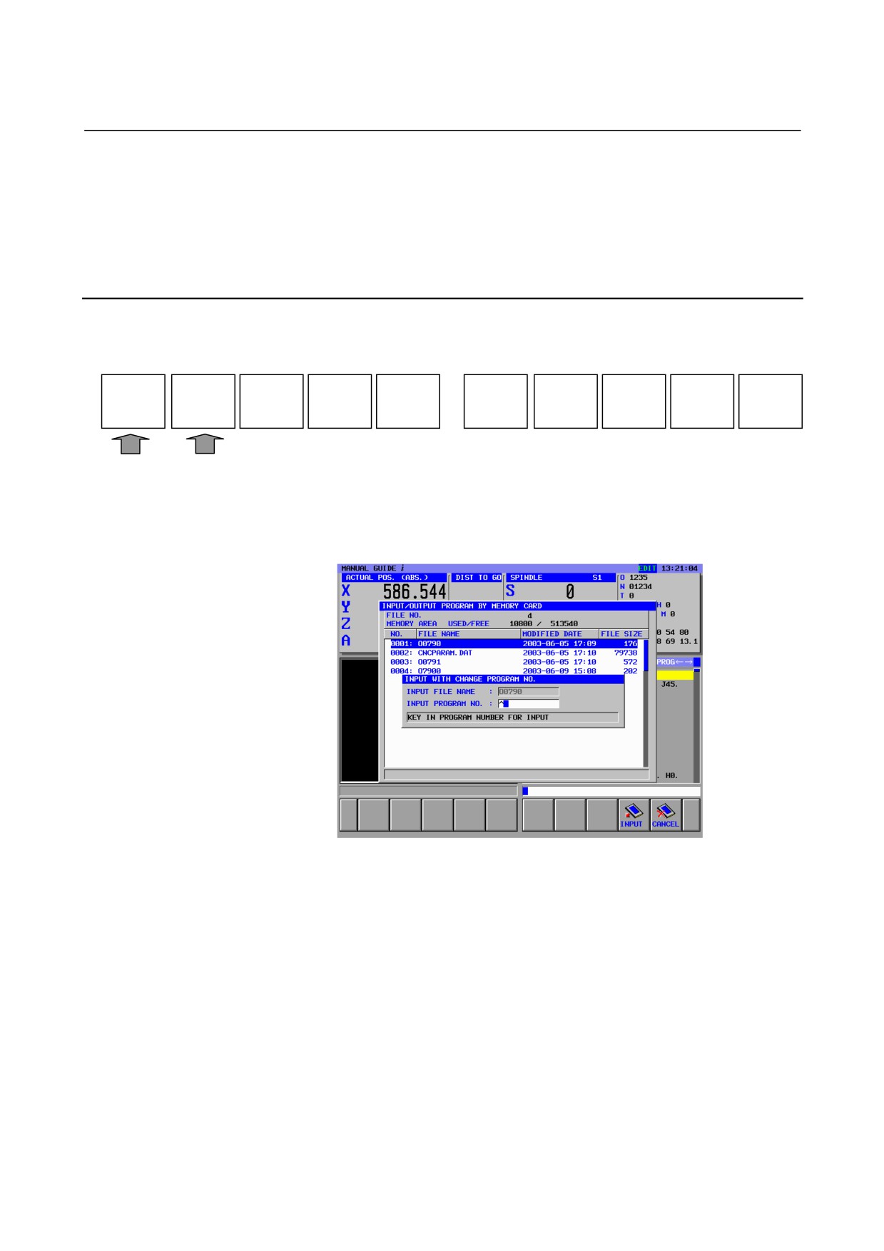
Pressing [INP.O.] displays the following window for changing the
reading program number, so enter the new program number and press
[INPUT].
When the file, in which all part program was outputted with file name
of “PROGRAM ALL”, is read to CNC with changing the program
number by [INP.O.], the program number of the 1st program is
changed to the new number.
- 282 -
B-63874EN/05
OPERATION
17.MEMORY CARD INPUT/OUTPUT FUNCTION
INPUT
INP.O.
DELETE
SEARCH
OUTPUT
FORMAT
RETURN
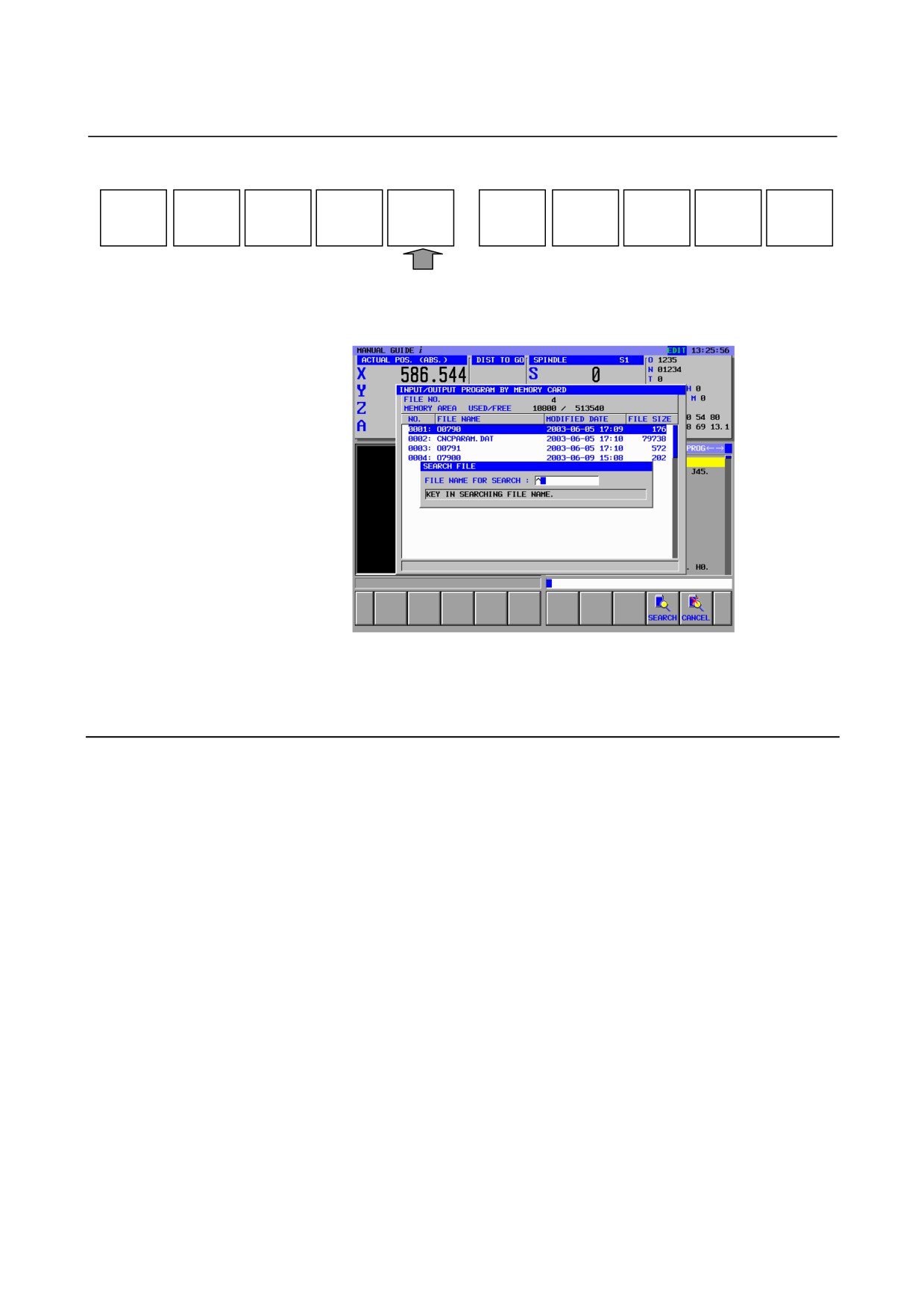
In order to search the file to be inputted to CNC, press [SEARCH] and
the following file searching window is displayed.
Enter the file name to be searched, and press [SEARCH], then the file
is searched if the file is stored in the memory card.
17.1.4 File Format Allowed for Memory Card Input/Output
Only text files can be input to and output from the memory card. The
file format described below must be observed.
<1> A file must start with "%" and "LF".
<2> A file must end with "%".
<3> For input, data read operation is skipped after the first "%" is
detected until an "LF" is detected.
<4> A block must end not with a semicolon (;) but with an "LF".
("LF" is 0A of ASCII code.)
<5> When a file containing lowercase alphabetic characters, kana
characters, and some special characters (such as $, \, and !) is
input, those characteristics are ignored.
<6> ASCII code is used as input/output code, regardless of the setting
parameter (ISO/EIA).
<7> Whether to output an "LF" only or an "LF, CR, CR" as an EOB
can be chosen using bit 3 (NCR) of parameter No. 0100.
<8> Characters usable for a file name
Alphabetic characters : A to Z
Numeric characters : 0 to 9
Special characters : $ & # % ' ( ) - @ ^ { } ~ ` ! _
- 283 -
17.MEMORY CARD INPUT/OUTPUT FUNCTION OPERATION
B-63874EN/05
17.2 MEMORY CARD INPUT/OUTPUT OF TOOL DATA
17.2.1 Memory Card Input/Output Screen of Tool Data
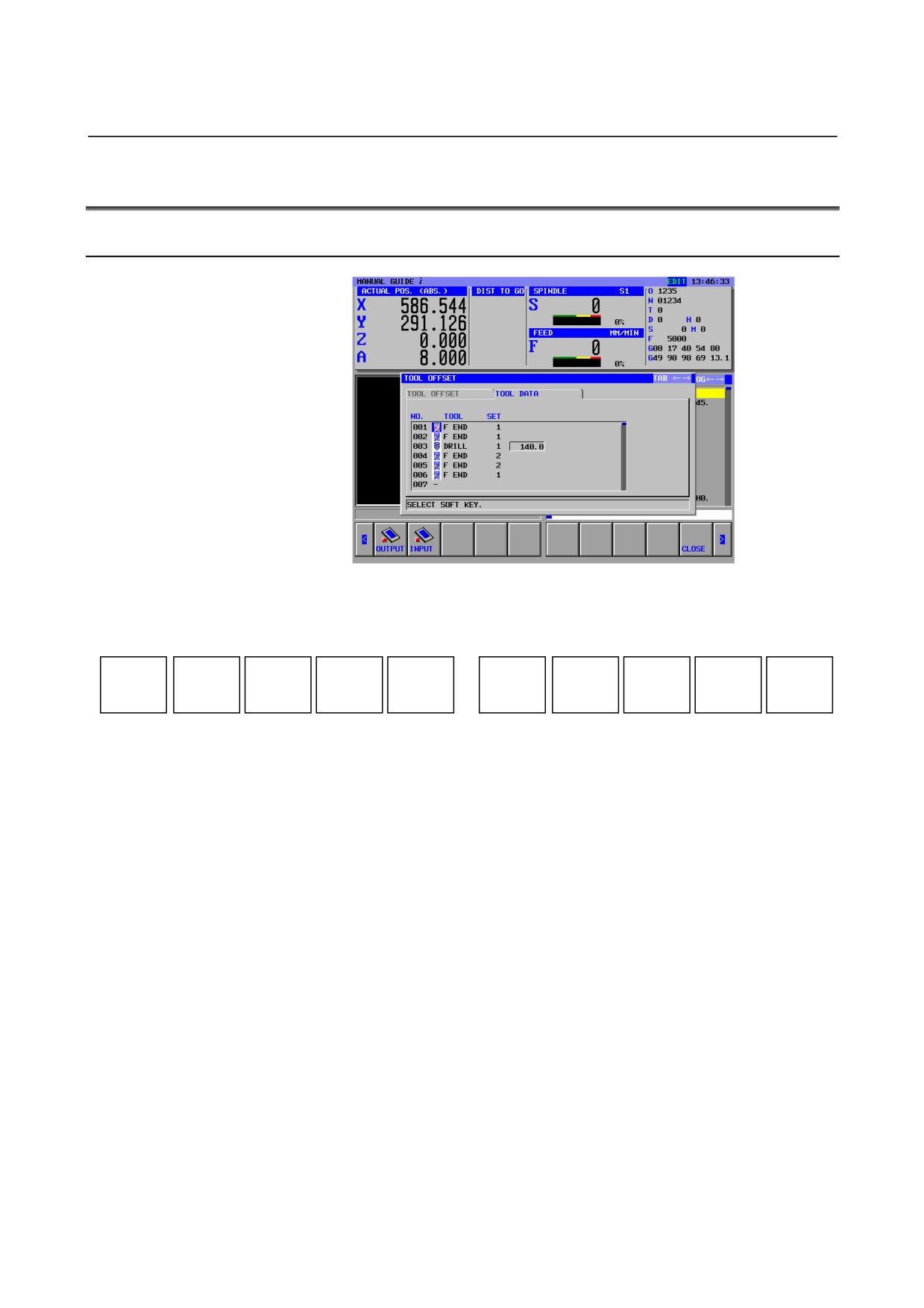
During displaying TOOL DATA window, the following soft-keys are
displayed by pressing the leftmost soft key [<] or rightmost soft key
[>] several times.
OUTPUT
INPUT
CLOSE
In order to input or output the tool data between memory card, select
EDIT mode on the machine operator’s panel.
Insert the memory card into the memory card slot on the LCD/MDI
panel.
- 284 -
B-63874EN/05
OPERATION
17.MEMORY CARD INPUT/OUTPUT FUNCTION
17.2.2 Memory Card Output Operation for Tool Data
OUTPUT
INPUT
CLOSE
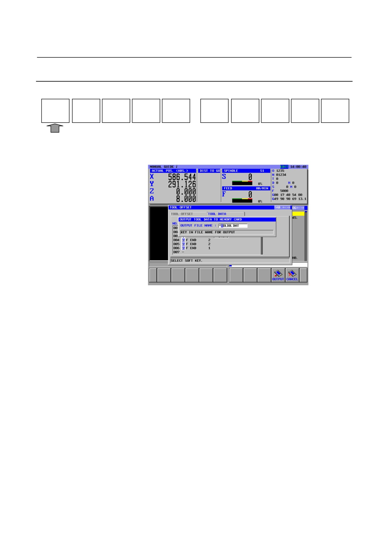
Pressing [OUTPUT] displays the following window for entering the
output file name.
Pressing [OUTPUT] without entering the file name outputs the tool
data with the file name “TOOLDAB.DAT].
In order to change the file name, enter the file name and press
[OUTPUT].
- 285 -
17.MEMORY CARD INPUT/OUTPUT FUNCTION OPERATION
B-63874EN/05
17.2.3 Memory Card Input Operation for Tool Data
OUTPUT
INPUT
CLOSE
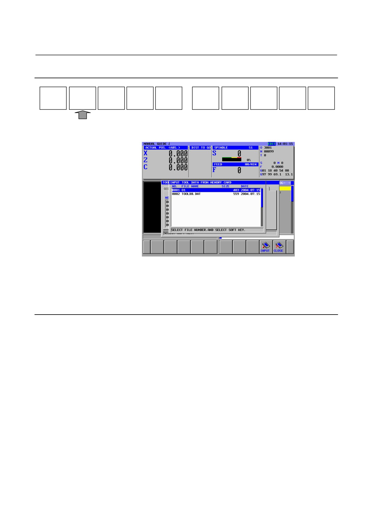
Pressing [INPUT] displays the following window of f the file list store
in the memory card.
Select the file in which tool data are stored and to be read to CNC by
placing the cursor by the cursor key.
Pressing
[INPUT] begins reading the tool data to
CNC form the
memory card.
17.2.4
Data Format
The following format can be inputted or outputted.
1. Machining Center
G1980 P_ K_ T_ S_ A_ ;
P : Offset Number (1 ˘
999)
K : Kind of Tool
T : Name of Tool
S : Setting
A : Tool Data
2. Lathe
G1981 P_ J_ K_ Q_ S_ A_ B_ ;
P : Offset Number (1 ˘
999)
J : Path Number (only multiple paths)
K : Kind of Tool
T : Name of Tool
S : Setting
A : Tool Data1
B : Tool Data2
- 286 -
B-63874EN/05
OPERATION
17.MEMORY CARD INPUT/OUTPUT FUNCTION
17.3 MEMORY CARD INPUT/OUTPUT OF FIXED FORM
SENTENCES
17.3.1 Memory Card Input/Output Screen of Fixed Form Sentences
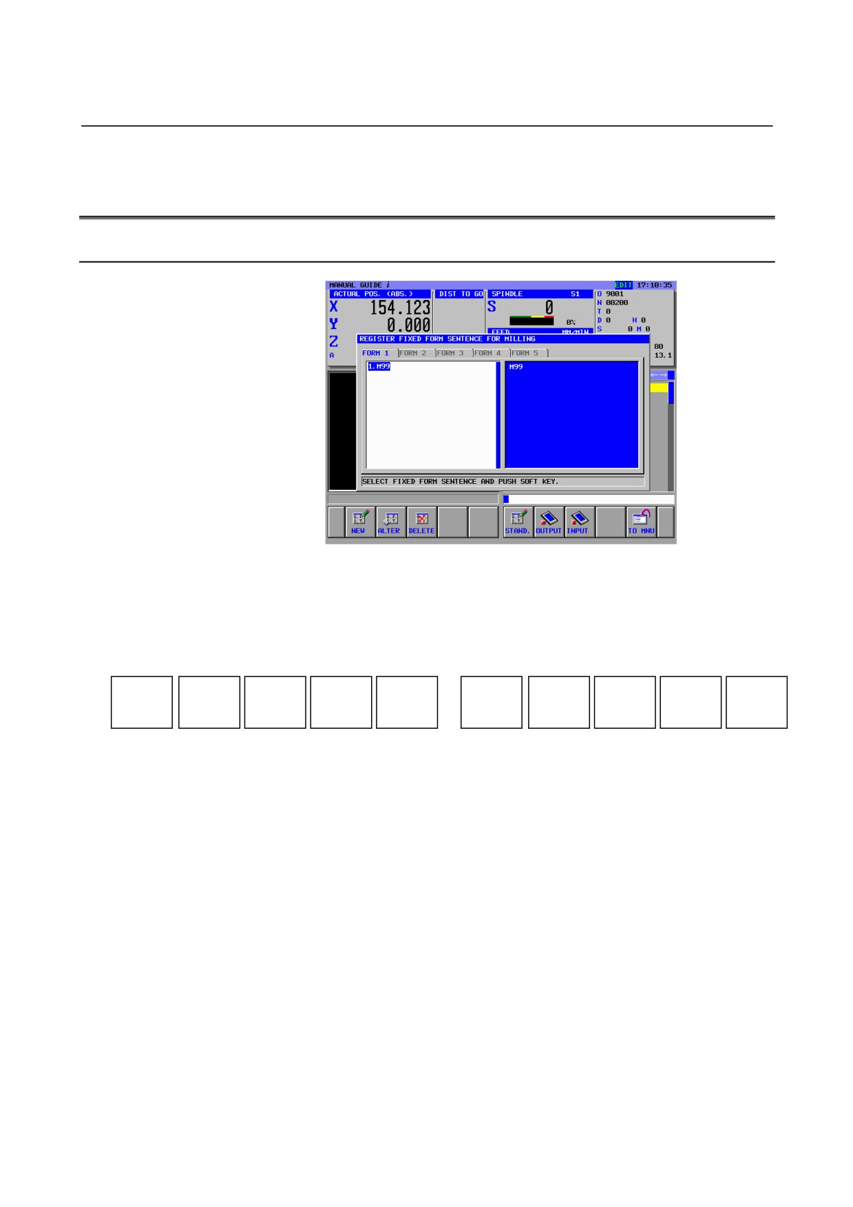
The following soft key is displayed after [SETING] is pushed and
“REGISTER FIXED FORM SENTENCES FOR MILLING” or
“REGISTER FIXED FORM SENTENCES FOR TURNING” is
selected.
NEW
ALTER
DELETE
STAND.
OUTPUT
INPUT
TO MNU
Select EDIT mode on the machine operator’s panel.
Insert the memory card into the memory card slot on the LCD/MDI
panel.
- 287 -
17.MEMORY CARD INPUT/OUTPUT FUNCTION OPERATION
B-63874EN/05
17.3.2 Output Fixed Form Sentences
NEW
ALTER
DELETE
STAND.
OUTPUT
INPUT
TO MNU
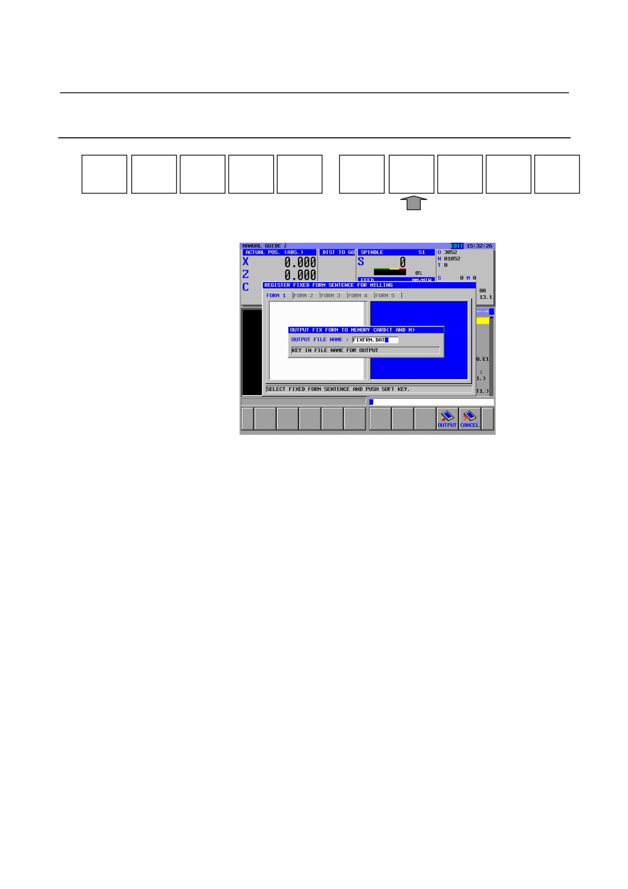
Pressing [OUTPUT] displays the following window for entering the
output file name.
Pressing [OUTPUT] without entering the file name outputs the fixed
form sentences with the file name “FIXFRM.DAT” (Output fixed
form sentences for milling and turning in a lump.)
In order to change the file name, enter the file name and press
[OUTPUT].
- 288 -
B-63874EN/05
OPERATION
17.MEMORY CARD INPUT/OUTPUT FUNCTION
17.3.3 Input Fixed Form Sentences
NEW
ALTER
DELETE
STAND.
OUTPUT
INPUT
TO MNU
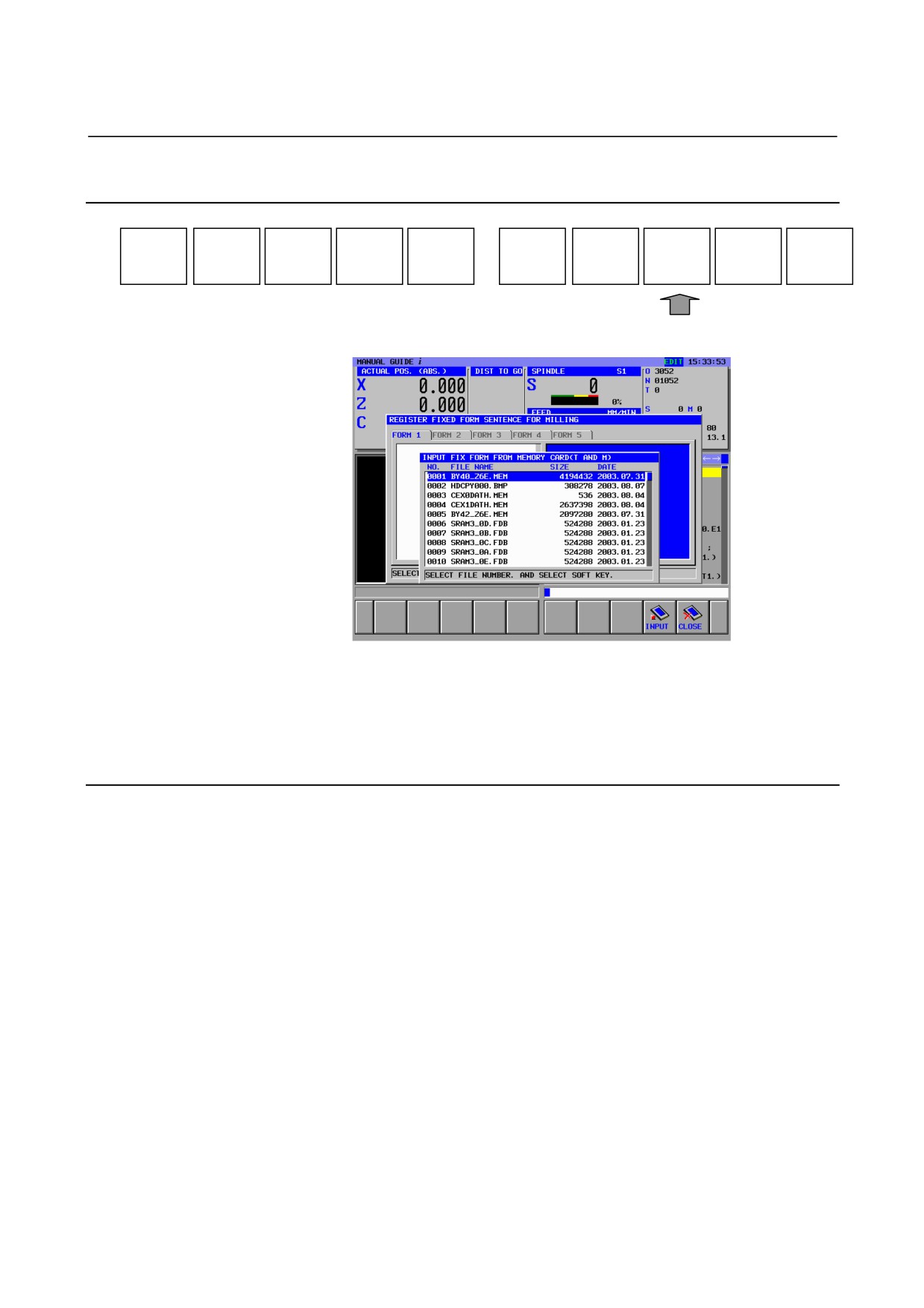
Pressing [INPUT] displays the following window of the file list store
in the memory card.
Select the file in which fixed form sentences are stored and to be
read to CNC by placing the cursor by the cursor key.
Pressing [INPUT] begins reading the tool data to CNC form the
memory card.
17.3.4 Format of Fixed Form Sentences
The following format can be inputted or outputted for fixed form
sentences.
<Mode>=_,<Tab>=_,<Title>=_,<Code>=_
Mode : Setting the mode of Fixed form sentences (Milling or
Turning).
1:Fixed Form Sentence for turning mode
2:Fixed Form Sentence for milling mode
3: Fixed Form Sentence for milling and turning mode
Tab : The number of tab(1 - 5)
Title : Setting the name of Fixed Form Sentence
Code : Setting Fixed Form Sentence
4 words, <Mode>=, <Tab>=, <Title>=, <Code>=, can’t be inputted as
the name of fixed form sentence or fixed form sentence.
- 289 -
18.HANDLING LARGE PROGRAMS OPERATION
B-63874EN/05
18
HANDLING LARGE PROGRAMS
- 290 -
B-63874EN/05
OPERATION
18.HANDLING LARGE PROGRAMS
18.1
SETTING A MAXIMUM PROGRAM SIZE THAT CAN BE
HANDLED
In parameter No. 14795, specify a maximum allowable memory size
to be used for program management.
Parameter
<1> No.14795#4 = 0 & No.14795#5 = 0
Set the maximum allowable program size to 250K bytes.
<2> No.14795#4 = 1 & No.14795#5 = 0
Set the maximum allowable program size to 500K bytes.
<3> No.14795#4 = 0 & No.14795#5 = 1
Set the maximum allowable program size to 1M bytes.
<4> No.14795#4 = 1 & No.14795#5 = 1
Set the maximum allowable program size to 2M bytes.
* A size of 200K bytes represents about 100,000 characters (4,000
blocks) when one block consists of 25 characters on average.
CAUTION
To specify a maximum allowable memory size
greater than 250K bytes in parameter No. 14795,
set an appropriate value in parameter No. 8781
(DRAM size that can be used by a C language
application).
To increase the DRAM size, the custom capacity
option is separately required.
* If the DRAM size is increased by 1M bytes by
using parameter No. 8781, about 500,000
characters (about 20,000 blocks) can be
increased as a guideline when one block consists
of 25 characters on average.
Restrictions
<1> If a large program is selected, the time required for switching
from the NC screen to MGi screen increases.
<2> If a large program is selected, a longer time is required to move
the program cursor as the program number increases.
- 291 -
18.HANDLING LARGE PROGRAMS OPERATION
B-63874EN/05
18.2
HANDLING A PROGRAM LARGER THAN THE MAXIMUM
ALLOWABLE SIZE
If the size of a program calculated according to the formula below
exceeds the maximum allowable memory size set in parameter No.
14795, the program cannot be handled on MANUAL GUIDE i.
Calculated size = (18 bytes)×(total number of blocks)+((number of
program characters)×1.1)
A program larger than the maximum allowable size is handled as
described below.
(1)
If the screen display is switched from the NC screen to the MGi
screen
If the screen display is switched from the NC screen to the MGi
screen when a program larger than the maximum allowable
memory size is selected, the screen described below appears.
All MGi operations are disabled. Only switching to the NC
screen with the function key is enabled.
(2)
If a selection is made on the program list screen
If a program larger than the maximum allowable memory size is
selected with the cursor and the [OPEN] soft key is pressed on
the program list screen, the [PROGRAM EXCEED MAXIMUM
SIZE.] message is displayed in the message display field on the
program list screen and the selection of the program is disabled.
CAUTION
If the program list screen contains only those
programs that are larger than the maximum
allowable memory size, the program list screen
cannot be closed. In this case, create a program to
close the program list screen.
(3)
If an O search is made
<1> If the program number of a program larger than the
maximum allowable memory size is entered into the key-in
buffer, and the
[O SRCH] soft key is pressed, the
[PROGRAM EXCEED MAXIMUM SIZE.] message is
displayed in the message display field on the base screen.
<2> If the program number of a program larger than the
maximum allowable memory size is not entered into the
key-in buffer, but the [O SRCH] soft key is pressed, the
program is not searched for.
- 292 -
B-63874EN/05
OPERATION
18.HANDLING LARGE PROGRAMS
(4) If a program larger than the maximum allowable memory size is
called by a subprogram call during operation or animated
simulation
If a program larger than the maximum allowable memory size is
called by a subprogram call during operation or animated
simulation, the
[PROGRAM EXCEED MAXIMUM SIZE.]
message is displayed in the program display field, and the
program is not displayed.
- 293 -
19.CALCULATOR FUNCTION
OPERATION
B-63874EN/05
19
CALCULATOR FUNCTION
- 294 -
B-63874EN/05
OPERATION
19.CALCULATOR FUNCTION
19.1
CALCULATOR FUNCTION
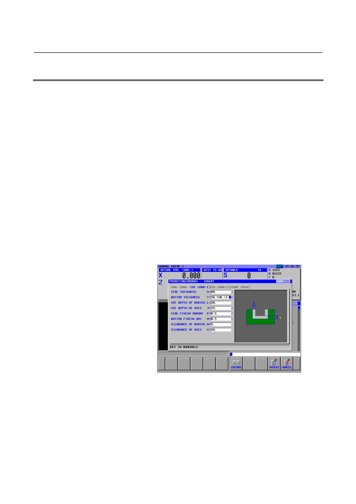
When numeric data is input, expressions for arithmetic operations,
trigonometric functions, square root calculations, and so forth can be
input for calculation.
1)
Applications
The fixed-point format calculation function can be used for cycle
input, arbitrary figure input, contour program input, setting of
various data items (basis setting, measurement condition setting,
calibration setting), relative coordinate preset input, and the
key-in buffer(*).
2)
Calculation methods
•
Arithmetic operations (addition, subtraction, multiplication,
and division)
Arithmetic operations are performed using the key
operations described below. The result of a calculation is
displayed at the cursor position for input data.
(1) Addition : 100.+200. [INPUT]
(2) Subtraction : 100.-200. [INPUT]
(3) Multiplication : 100.*200. [INPUT]
(4) Division : 100./200. [INPUT]
Example of input
- 295 -
19.CALCULATOR FUNCTION
OPERATION
B-63874EN/05
•
Trigonometric functions
(sine, cosine, tangent, arcsine,
arccosine, arctangent)
Trigonometric function calculations are made using the key
operations described below. The result of a calculation is
displayed at the cursor position for input data.
(1) Sin : SIN(45) [INPUT]
(2) Cosine : COS(45) [INPUT]
(3) Tangent : TAN(45) [INPUT]
(4) Arcsine : ASIN(0.5) [INPUT]
(5) Arccosine : ACOS(0.5) [INPUT]
(6) Arctangent : ATAN(20,2) [INPUT]
(Note that for an arctangent calculation, a special format
using two arguments is required. Enter data according to the
format ATAN(a,b). arctan(a/b) is calculated.)
For a calculation, () is required at all times.
•
Square root
A square root calculation is made using the key operations
described below. The result of a calculation is displayed at
the cursor position for input data.
(1) Square root : SQRT(45) [INPUT]
For a calculation, () is required at all times.
•
Exponential functions
Exponential function calculations are made using the key
operations described below. The result of a calculation is
displayed at the cursor position for input data.
(1) Exponential function 1 (An exponential function of e =
2.718... can be calculated.) :
EXP(4) [INPUT]
(2) Exponential function 2 ("a" raised to the power of "b"
can be calculated.) :
PWR(4,3) [INPUT]
(Note that for a calculation of exponential function 2, a
special format using two arguments is required. Enter data
according to the format PWR(a,b). "a" raised to the power
of "b" is calculated.)
For a calculation, () is required at all times.
•
Logarithmic functions
(common logarithm, natural
logarithm)
Logarithmic function calculations are made using the key
operations described below. The result of a calculation is
displayed at the cursor position for input data.
(1) Common logarithm : LOG(45) [INPUT]
(2) Natural logarithm : LN(45) [INPUT]
For a calculation, () is required at all times.
- 296 -
B-63874EN/05
OPERATION
19.CALCULATOR FUNCTION
•
Absolute value
An absolute value calculation is made using the key
operations described below. The result of a calculation is
displayed at the cursor position for input data.
(1) Absolute value : ABS(-45) [INPUT]
For a calculation, () is required at all times.
•
Rounding
Rounding operations are performed using the key
operations described below. The result of a calculation is
displayed at the cursor position for input data.
(1) Rounding 1 (rounding off to an integer) :
RND(1.234) [INPUT]
(2) Rounding 2 (rounding off "a" to the decimal places
specified by "b") :
RND2(1.267,0.01) [INPUT]
(Note that for a calculation of rounding 2, a special format
using two arguments is required. Enter data according to the
format RND(a,b). The value of "a" is rounded off to the
decimal places specified by "b". As "b", do not specify a
value other than 1, 0.1, 0.01, and so forth.)
For a calculation, () is required at all times.
•
Discarding
This operation discards all decimal places. A discarding
operation is performed using the key operations described
below. The result of a calculation is displayed at the cursor
position for input data.
(1) Discarding : FIX(1.234) [INPUT]
For a calculation, () is required at all times.
•
Circle ratio
A circle ratio calculation is made using the key operations
described below. The circle ratio 3.14... is indicated.
(1) Circle ratio : PAI [INPUT]
(*)
In the case of key-in buffer input, no decimal point is assigned
when an integer is produced as the result of a calculation. In
cases other than key-in buffer input, the respective input formats
are to be followed.
- 297 -
20.AUTOMATIC SETTING OF INITIAL VALUE DATA
OPERATION
B-63874EN/05
20
AUTOMATIC SETTING OF INITIAL
VALUE DATA
- 298 -
B-63874EN/05
OPERATION
20.AUTOMATIC SETTING OF INITIAL VALUE DATA
20.1
AUTOMATIC SETTING OF INITIAL VALUES ON THE
INPUT DATA SCREEN
Data previously entered on the data input screen of the cycle menu or
drawing definition menu (blank figure block and tool definition block)
is automatically set as initial input value data.
Accordingly, the operator needs to enter cycle menu and drawing
definition menu data just once at the beginning. Then, the previously
entered data is set as initial values.
The input data items other than the [TOOL COND] tab of the cycle
menu are automatically set. The input data of the [TOOL COND] tab
is automatically set according to Section 20.2, "AUTOMATIC TOOL
DEFINITION BLOCK COPY".
For the figure menu, input data depends on the drawing data, so that
no initial values are automatically set.
20.2
AUTOMATIC TOOL DEFINITION BLOCK COPY
If the user does not use Tool Data Base function, the user needs to
specify the tool definition block of Drawing Definition menu before
Milling cycles or Turning cycles.
In that case, the user specifies the same data as the tool condition data
of each cycle menu.
This time, in each cycle menu, the tool condition data is set
automatically by copying the data of tool definition block.
That is, when data is input in the tool definition block of the drawing
definition menu, the data is once saved as internal data. Then, when
data is to be input according to the cycle menu, the tool definition
block data saved internally is copied as tool condition input data.
Accordingly, the operator just needs to enter a tool definition block
initially. Then, the operator need not enter tool condition data in
subsequent cycle menus.
The following tool definition block data is saved as internal data:
•
Milling tool
1) TOOL DIAMETER (D)
•
Turning tool
1) NOSE RADIUS (R)
2) CUT EDGE ANGLE (A)
3) NOSE ANGLE (B)
- 299 -
21.SUPPORT FOR FOLDER MANAGEMENT (FOR Series 30i ONLY) OPERATION
B-63874EN/05
21
SUPPORT FOR FOLDER MANAGEMENT
(FOR Series 30i ONLY)
This function is supported only for the Series 30i.
- 300 -
B-63874EN/05
OPERATION 21.SUPPORT FOR FOLDER MANAGEMENT (FOR Series 30i ONLY)
21.1 PROGRAM LIST SCREEN
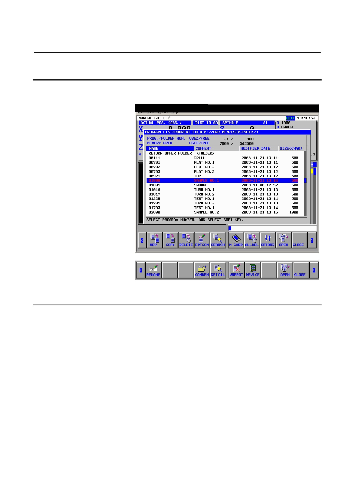
This section describes the specifications of folder management on the
program list screen.
21.1.1 Data Displayed in the Program List
(1) Program number
This program number is equivalent to a conventional program
number.
(2) Comment
If a comment is longer than the displayable range, "..." is
indicated at the end.
(3) Program update time (Year/month/day/hours/minutes)
(4) Program size (number of characters)
(5)
[RETURN UPPER FOLDER]
(6) Program attribute (whether to enable editing)
The character "R" is indicated at the right end of a program that
must not be edited.
- 301 -
21.SUPPORT FOR FOLDER MANAGEMENT (FOR Series 30i ONLY) OPERATION
B-63874EN/05
21.1.2 Operations Added for the Program List Screen
(1) Changing the program name/folder name
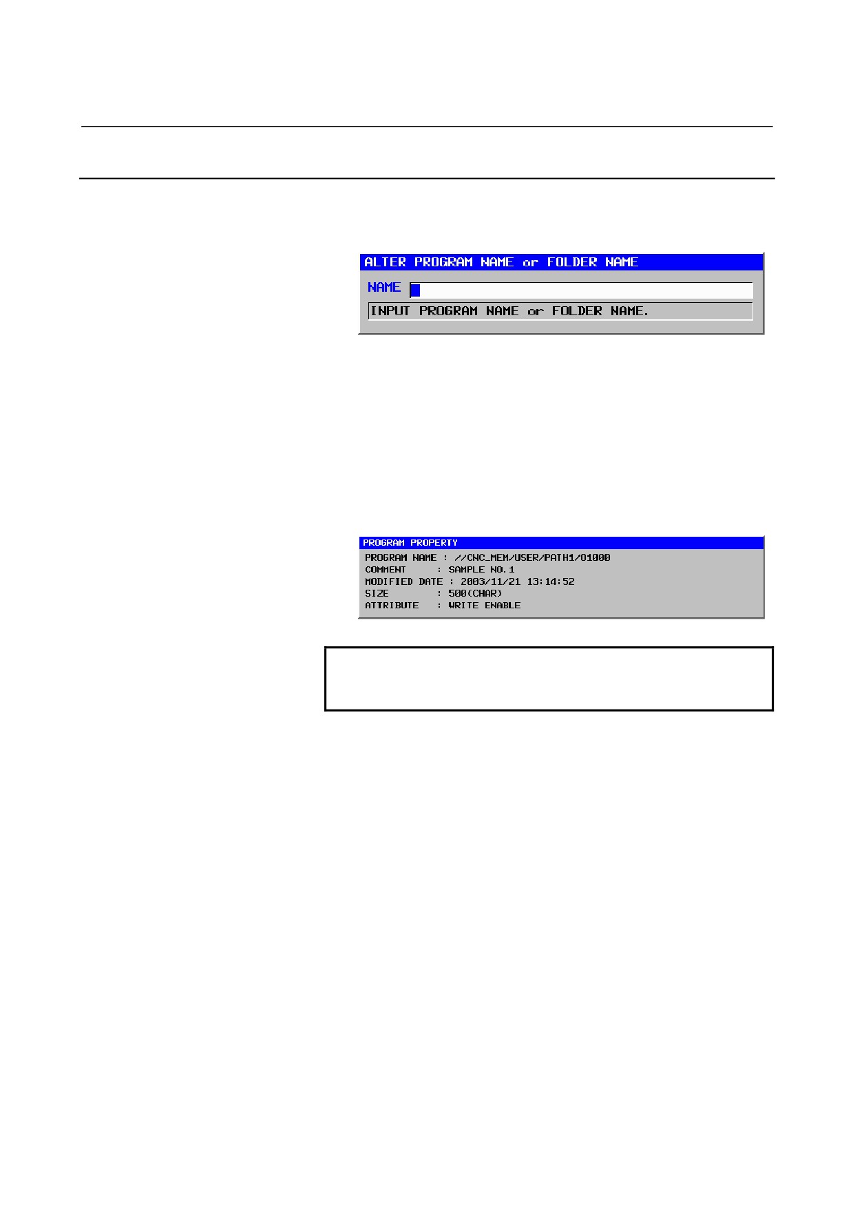
Pressing the
[RENAME] soft key displays the
[ALTER
PROGRAM NAME or FOLDER NAME] screen.
(2) Program detail information
Pressing the
[DETAIL] soft key displays the
[PROGRAM
PROPERTY] screen. This screen displays the following
information:
<1> Program name (Character string: 32 characters max.) (NOTE)
<2> Comment (Character string: 48 characters max.) (NOTE)
<3> Date and time of program modification
(Year/month/day/hours/minutes/seconds)
<4> Program size (Number of characters)
<5> Program attribute (Whether to enable editing)
NOTE
With the Series 30i, lowercase letters can be used
for a program name and comment.
(3) Program condensation
Pressing the [CONDEN] soft key condenses programs.
(4) Changing the program attribute (write protection)/folder attribute
(write protection)
Pressing the
[WRPROT] soft key changes the attribute
cyclically.
The character "R" is indicated at the right end of a program that
must not be edited.
- 302 -
B-63874EN/05
OPERATION 21.SUPPORT FOR FOLDER MANAGEMENT (FOR Series 30i ONLY)
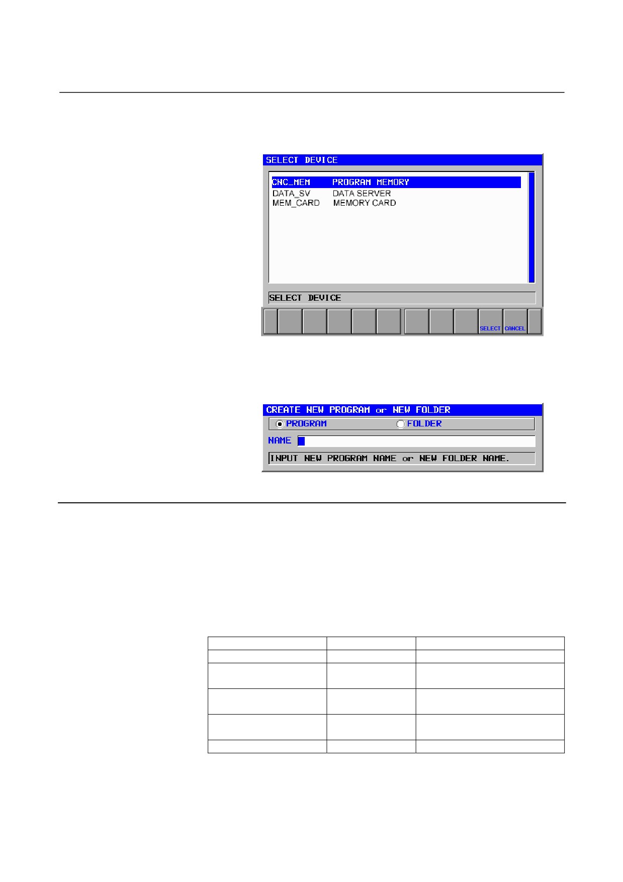
(5) Device selection
Pressing the
[DEVICE] soft key displays the
[SELECT
DEVICE] screen.
When you select a device then press the [SELECT] soft key, the
list of programs on the device is displayed.
(6) Creation of a new program
In the check box, choose whether to create a program or folder.
21.1.3 Support for the Data Server
(1) MGi supports the editing and operation of a program on the data
server.
By switching the device on the program list screen, a program on
the data server can be handled in the same way as a program in
the program memory.
However, there are differences in operation as indicated below.
The differences comply with the operation specifications of the
NC screen.
Operation
Program memory
Data Server
Creating a new program
Possible
Impossible
The program currently selected
Copying a program
Possible
cannot be copied.
The program currently selected
Deleting a program
Possible
cannot be deleted.
The program currently selected
Renaming a program
Possible
cannot be renamed.
Memory card input/output
Possible
Impossible
(2) The other functions on the data server (such as setting and FTP
transfer) are to be performed on the NC screen (program list
screen).
- 303 -
21.SUPPORT FOR FOLDER MANAGEMENT (FOR Series 30i ONLY) OPERATION
B-63874EN/05
21.2 MEMORY CARD I/O SCREEN
The current folder is input/output.
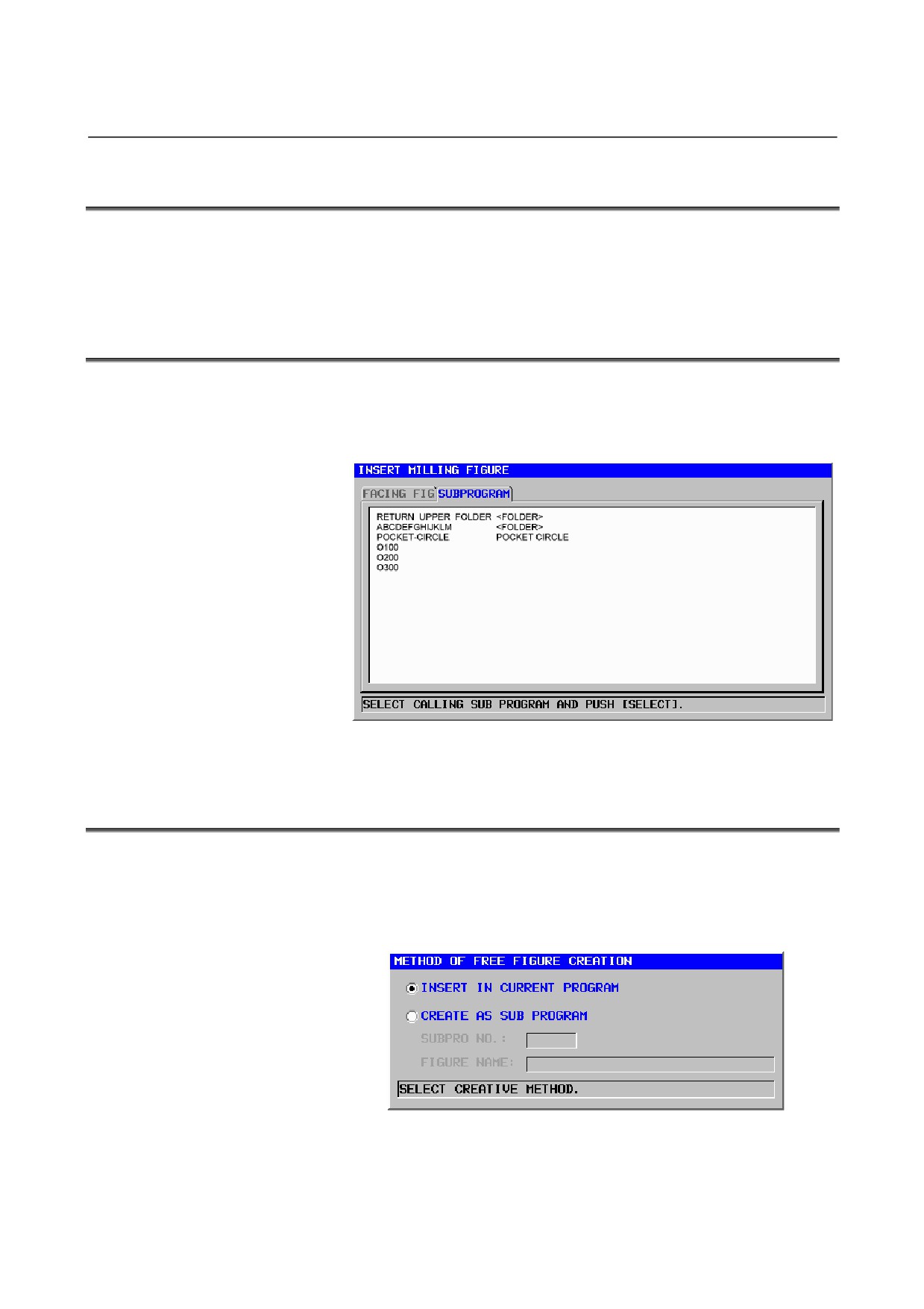
21.3 SUBPROGRAM TAB ON THE CYCLE FIGURE
SELECTION SCREEN
The folder containing the program currently selected as the main
program is displayed as the current folder. When a folder is selected
using the same operation as for the list of programs, the programs in
the folder are displayed.
21.4 OUTPUT OF AN ARBITRARY FIGURE AS A
SUBPROGRAM
As a folder for subprogram output, one of the following can be
selected:
<1> Current folder
<2> Common program folder
(//CNC_MEM/USER/LIBRARY/)
- 304 -
B-63874EN/05
OPERATION 21.SUPPORT FOR FOLDER MANAGEMENT (FOR Series 30i ONLY)
21.5 DISPLAY OF ARBITRARY FIGURES OF M98
SUBPROGRAMS
The following folders are searched in this order, and the program first
found is displayed:
<1> Folder containing the main program
<2> Common program folder
(//CNC_MEM/USER/LIBRARY/)
- 305 -
22.SCREEN HARD COPY
OPERATION
B-63874EN/05
22
SCREEN HARD COPY
In order to make a copy to memory card of the screen of MANUAL
GUIDE i, you need to operate as follows.
1.
Setting of parameters
In addition to the parameter for hard copy of standard CNC
screen, No.3301#7HDC = 1, setting of the parameter for C
executor, No.8650#4CKM = 1, is necessary.
And furthermore, you need to set the parameter for memory card,
No.20 = 4.
2.
Operations
Mount a memory card and display a necessary screen, then push
“SHIFT” key more than 5 seconds.
Release “SHIFT” key after checking the clock display on the
screen stops. The clock display will move again when copying
the screen completes.
3.
Created File
By the above operations, new file with name of
“Hdcpy***.bmp” is created in the memory card. *** is the serial
number and numbered as 001, 002. However, once the CNC
power is turned off, this number is initialized to 000 from the
next time of creating hard copy file.
- 306 -
B-63874EN/05
OPERATION
23.DISPLAYING MACHINING TIME (FOR Series 16i/18i/21i ONLY)
23
DISPLAYING MACHINING TIME (FOR
Series 16i/18i/21i ONLY)
During simulation, the logical machining time of each block is
calculated from feedrate and distance for movement. And the result is
displayed.
- 307 -
23.DISPLAYING MACHINING TIME (FOR Series 16i/18i/21i ONLY) OPERATION
B-63874EN/05
23.1 FORMAT OF MACHINING TIME DATA
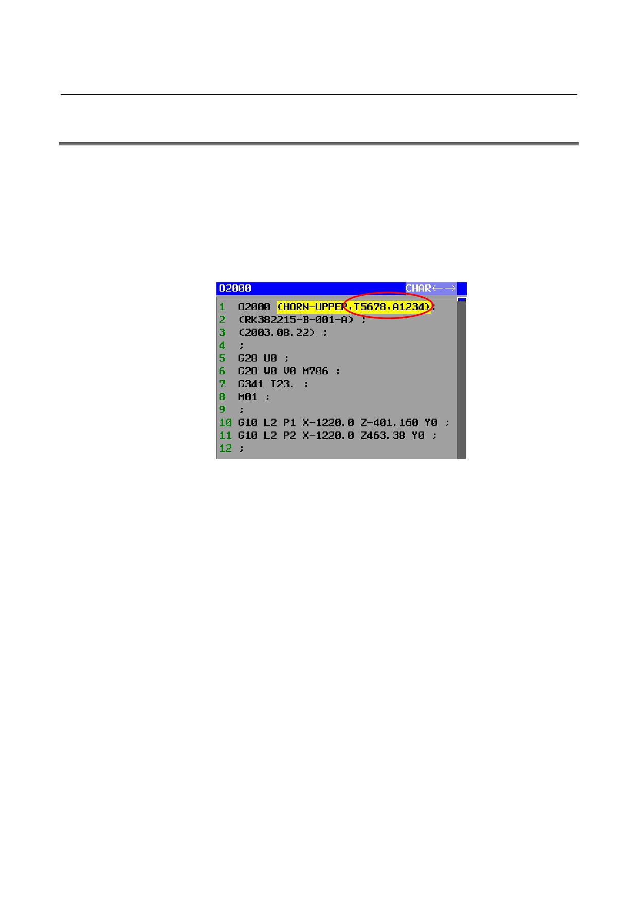
Machining time data is inserted in program and it is conserved.
The place when the data are inserted is in the comment that is next to
O number.
The format is “,T_,A_”. “,T_” is cutting time data and “,A_” is
non-cutting time data.
Ex. Cutting time is 1h 34’ 38”( = 5678 s) and non-cutting time is 20’
34”( = 1234 s)
- 308 -
B-63874EN/05
OPERATION
23.DISPLAYING MACHINING TIME (FOR Series 16i/18i/21i ONLY)
23.2 OPERATION FOR INSERTING MACHINING TIME
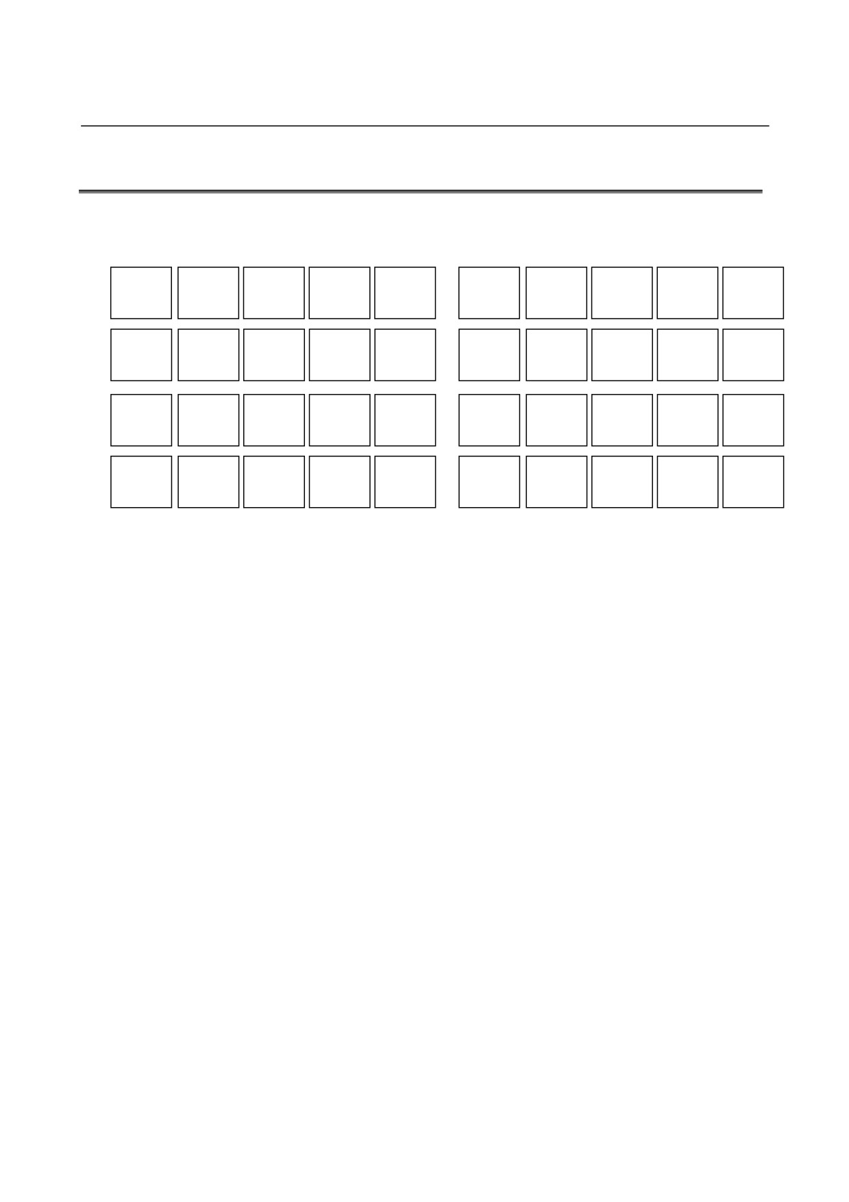
The following soft keys are displayed on MEM mode after [SIMLAT]
soft key is pushed.
REWIND
START
PAUSE
SINGLE
STOP
INIT
CUTDSP
INTERF
TLPATH
GRPOFF
LARGE
SMALL
AUTO
REVERS
ROTATE
←MOVE
MOVE→
↑MOVE
↓MOVE
CENTER
WK SET
T-OFS
SETING
REWIND
O LIST
CHGDSP
N SRCH
O SRCH
ACTPOS
PRESET
INSERT
After [START] is pushed and simulation is started, the machining
time is calcurated and it is kept in the memory temporarily. After
that, the color of [INSERT] soft key is changed. If [INSERT] soft
key is pushed in this state, the message “MACHINE TIME DATA
IS INSERTED. OK?” is displayed. Then, if “YES” is selected, the
machining time data are inserted to the end of comment.
- 309 -
23.DISPLAYING MACHINING TIME (FOR Series 16i/18i/21i ONLY) OPERATION
B-63874EN/05
NOTE
1 Don’t operate the machine during inserting
machining time data.
2 When the machining time isn’t kept in the memory,
the machining time can’t be inserted.
3 When the program has been protected, the
machining time can’t be inserted.
4 The machining time can’t be inserted during
operation.
5 All paths must be on MEM mode to insert
machining time data. When at least one path isn’t
on MEM mode, The machining time can’t be
inserted.
6 Even if all path is on MEM mode, if at least one
path is on background editing, machining time data
can’t be inserted.
7 When the machining time data are inserted on one
path, the machining time data are inserted on other
paths too. But when simulation for each path is
executed, the machining time data are inserted on
only the path in which the simulation is executed.
- 310 -
B-63874EN/05
OPERATION
23.DISPLAYING MACHINING TIME (FOR Series 16i/18i/21i ONLY)
23.3 DISPLAY MACHINING TIME
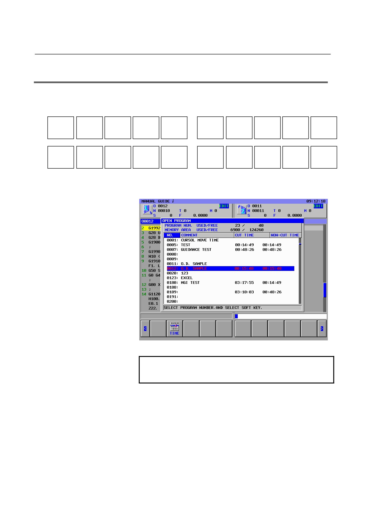
The following soft keys are displayed after [O LIST] soft key is
pushed.
NEW
COPY
DELETE
EDTCOM
SEARCH
M CARD
ALLDEL
SRTORD
OPEN
CLOSE
TIME
If
[TIME] soft key is pushed, the indication of modified date and
program size are changed to machining time as follows.
If [TIME] is pushed again, modified date is displayed again.
NOTE
The parameters about displaying machining time are
from 27390 to 27392.
- 311 -