FANUC MANUAL GUIDE i. OPERATOR’S MANUAL - page 13
1.MILLING
CYCLE MACHINING TYPES
B-63874EN/05
NOTE
1 When you use rigid tapping mode M code
command (No.5200#0=0), the system refers to
No.5210 or No.5212 as the value of M code.
Therefore, please set No.5210 or No.5212 to
suitable value before machining.
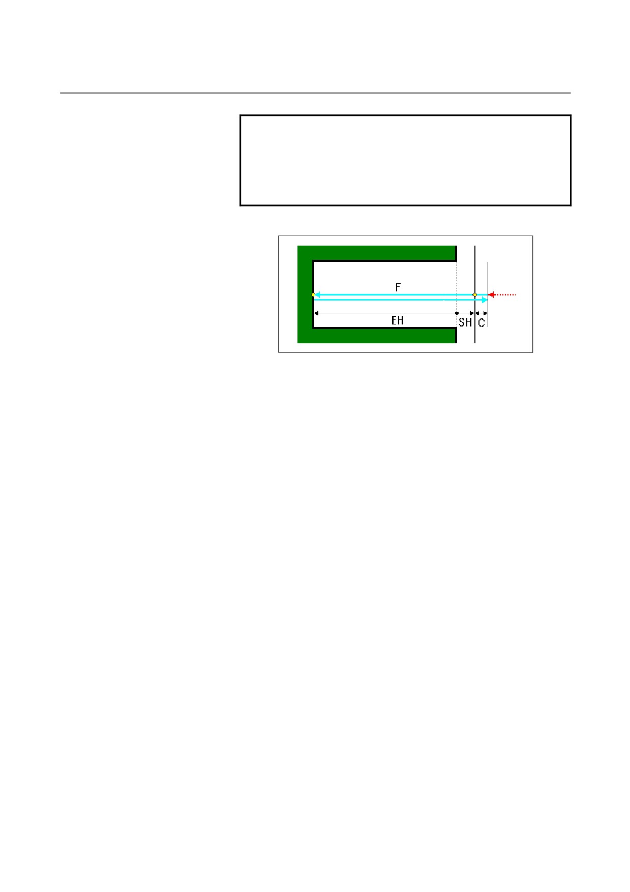
• Tool path
<1> Move the tool to the position "cutting start position + clearance
(C)" in rapid traverse.
<2> Move the tool to the cutting end position at the cutting feedrate
(F).
<3> Stop the spindle.
<4> Rotate the spindle in reverse.
<5> Move the tool to the position "cutting start position + clearance
(C)" at the cutting feedrate (F).
<6> Cause the spindle to start rotating normally.
- 342 -
B-63874EN/05
CYCLE MACHINING TYPES
1.MILLING
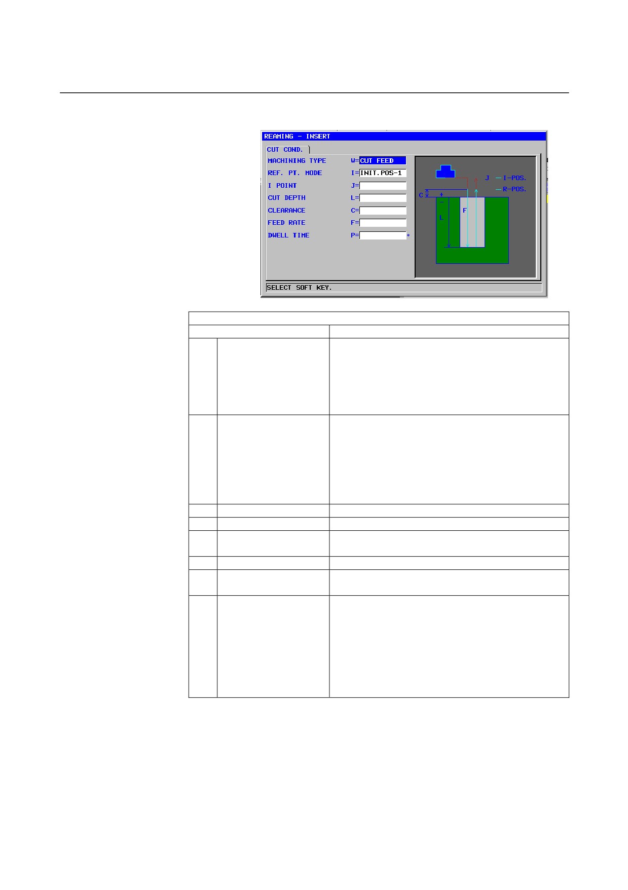
Reaming: G1003
CUT COND.
Data item
Meaning
W
MACHINING TYPE
[CUT]
: The tool retracts from the hole bottom in
cutting feed.
(initial value)
[RAPID]
: The tool retracts from the hole bottom in
rapid traverse.
[DWELL] : After dwelling at the hole bottom, the tool
retracts in cutting feed.
I
REF. PT. MODE
[INIT-1]: An R position return is made in moving
between holes. Finally, a return is made to
the I point.
(initial value)
[INIT-2]: All movements between holes, including the
last return, are made as an I point return.
[REF.] : All movements between holes, including the
last return, are made as an R position return.
J
I POINT
Coordinate of the I point
(COPY)
L
CUT DEPTH
Cut depth (radius value, negative value)
C
CLEARANCE
Distance between the workpiece surface and R
position (radius value, positive value)
(COPY)
F
FEED RATE
Cutting feedrate (positive value)
(COPY)
P*
DWELL TIME
Dwell time at the hole bottom. If omitted, 0 is
assumed. (units of seconds, positive value)
(COPY)
Z
APROCH MOTION
[2 AXES] : When moving from the current position to
the machining start point, the tool first
moves in the machining plane in two-axis
synchronous operation and then moves
along the tool axis. (initial value)
[3 AXES] : The tool moves from the current position
to the machining start point in three-axis
synchronous operation.
- 343 -
1.MILLING
CYCLE MACHINING TYPES
B-63874EN/05
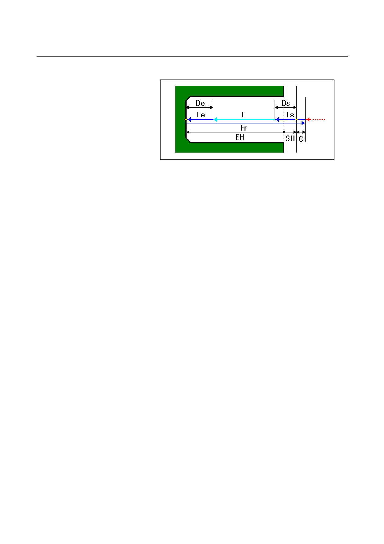
• Tool path
<1> Move the tool to the position "cutting start position + clearance
(C)" in rapid traverse.
<2> Move the tool to the cutting end position at the cutting feedrate
(F).
<3> Move the tool to the position "cutting start position + clearance
(C)" at the returning feedrate (Fr).
- 344 -
B-63874EN/05
CYCLE MACHINING TYPES
1.MILLING
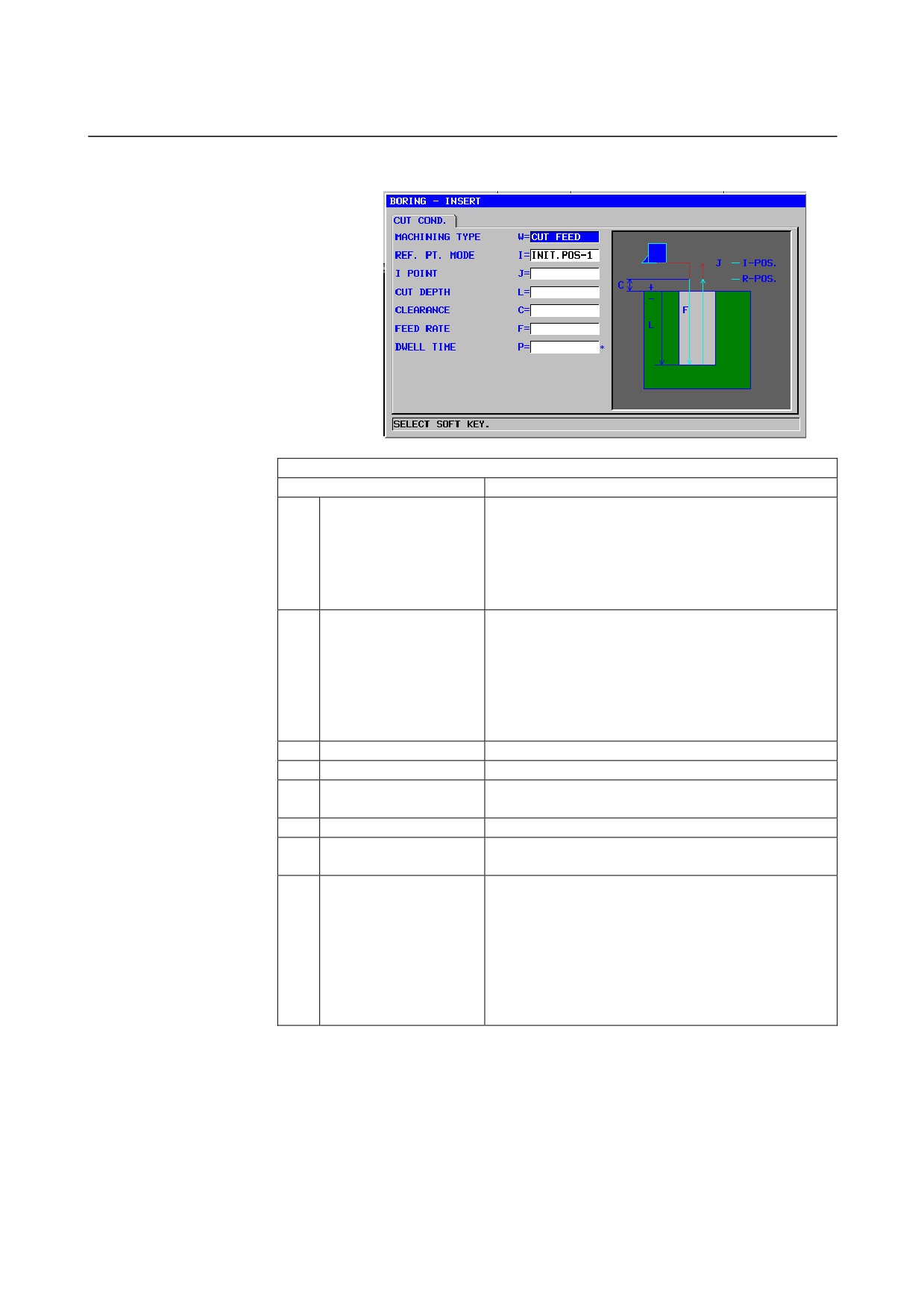
Boring: G1004
CUT COND.
Data item
Meaning
W
MACHINING TYPE
[CUT]
: The tool retracts from the hole bottom in
cutting feed.
(initial value)
[RAPID]
: The tool retracts from the hole bottom in
rapid traverse.
[DWELL] : After dwelling at the hole bottom, the tool
retracts in cutting feed.
I
REF. PT. MODE
[INIT-1]: An R position return is made in moving
between holes. Finally, a return is made to
the I point.
(initial value)
[INIT-2]: All movements between holes, including the
last return, are made as an I point return.
[REF.] : All movements between holes, including the
last return, are made as an R position return.
J
I POINT
Coordinate of the I point
(COPY)
L
CUT DEPTH
Cut depth (radius value, negative value)
C
CLEARANCE
Distance between the workpiece surface and R
position (radius value, positive value)
(COPY)
F
FEED RATE
Cutting feedrate (positive value)
(COPY)
P*
DWELL TIME
Dwell time at the hole bottom. If omitted, 0 is
assumed. (units of seconds, positive value)
(COPY)
Z
APROCH MOTION
[2 AXES] : When moving from the current position to
the machining start point, the tool first
moves in the machining plane in two-axis
synchronous operation and then moves
along the tool axis. (initial value)
[3 AXES] : The tool moves from the current position
to the machining start point in three-axis
synchronous operation.
- 345 -
1.MILLING
CYCLE MACHINING TYPES
B-63874EN/05
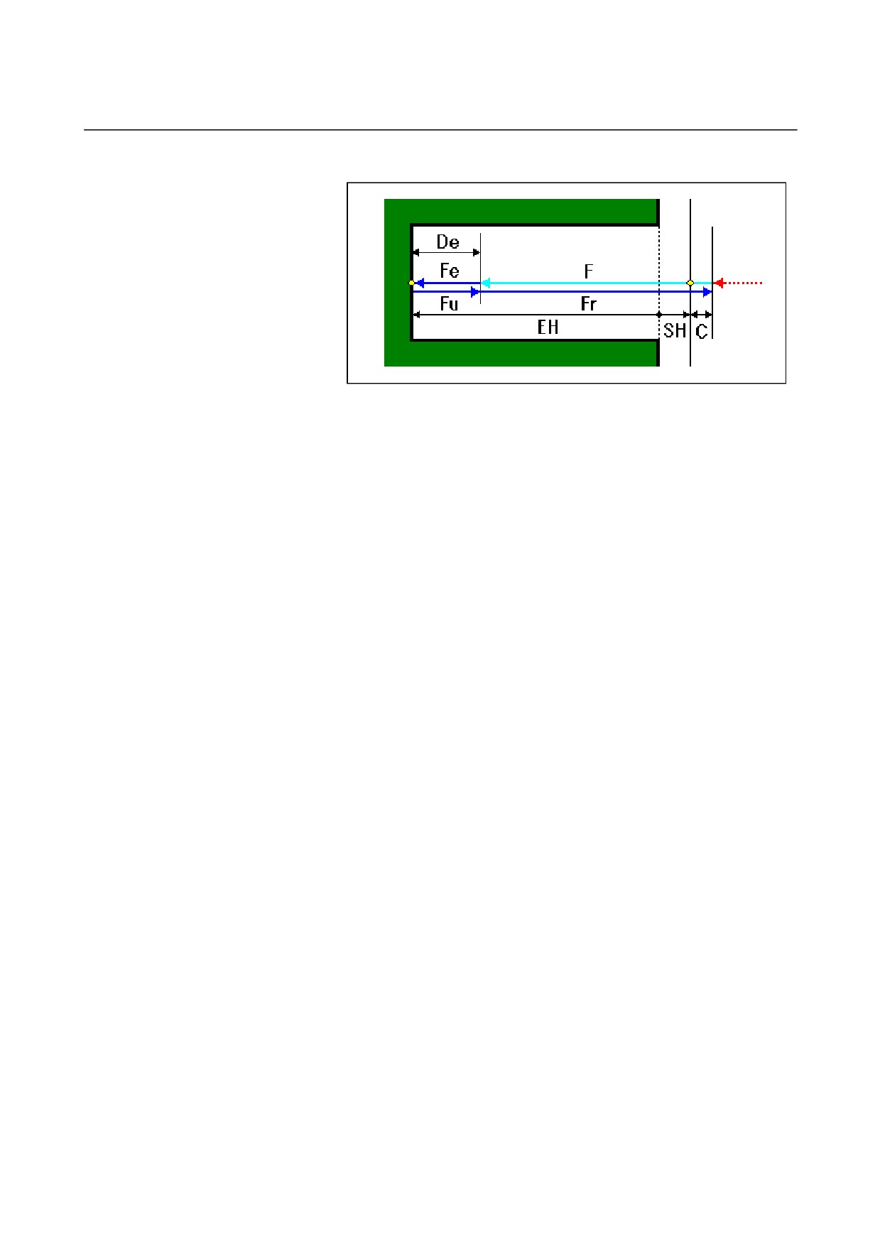
• Tool path
<1> Move the tool to the position "cutting start position + clearance
(C)" in rapid traverse.
<2> Move the tool to the cutting end position at the cutting feedrate
(F).
<3> Move the tool to the position "cutting start position + clearance
(C)" at the returning feedrate (Fr).
- 346 -
B-63874EN/05
CYCLE MACHINING TYPES
1.MILLING
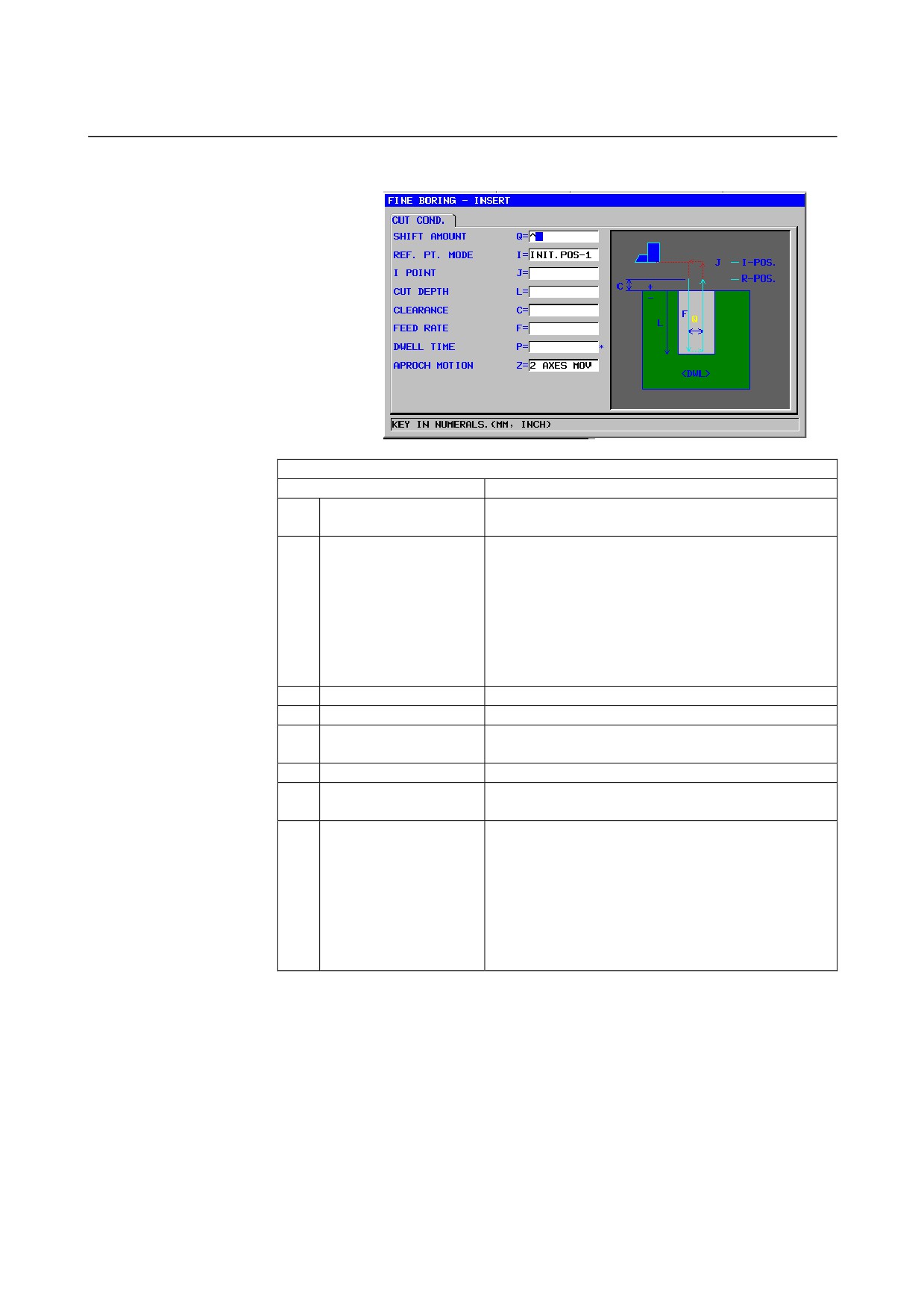
Fine Boring: G1005
CUT COND.
Data item
Meaning
Q
SHIFT AMOUNT
Shift amount (radius value) at the hole bottom after
spindle orientation
(COPY)
I
REF.PT.MODE
[INIT-1] : An R position return is made in moving
between holes. Finally, a return is made to
the I point.
(initial value)
[INIT-2] : All movements between holes, including the
last return, are made as an I point return.
[REAF.]: All movements between holes, including the
last return, are made as an R position
return.
J
I POINT
Coordinate of the I point
(COPY)
L
CUT DEPTH
Cut depth (radius value, negative value)
C
CLEARANCE
Distance between the workpiece surface and R
position (radius value, positive value)
(COPY)
F
FEED RATE
Cutting feedrate (positive value)
(COPY)
P*
DWELL TIME
Dwell time at the hole bottom. If omitted, 0 is
assumed. (units of seconds, positive value)
(COPY)
Z
APROCH MOTION
[2 AXES] : When moving from the current position to
the machining start point, the tool first
moves in the machining plane in two-axis
synchronous operation and then moves
along the tool axis. (initial value)
[3 AXES] : The tool moves from the current position
to the machining start point in three-axis
synchronous operation.
- 347 -
1.MILLING
CYCLE MACHINING TYPES
B-63874EN/05
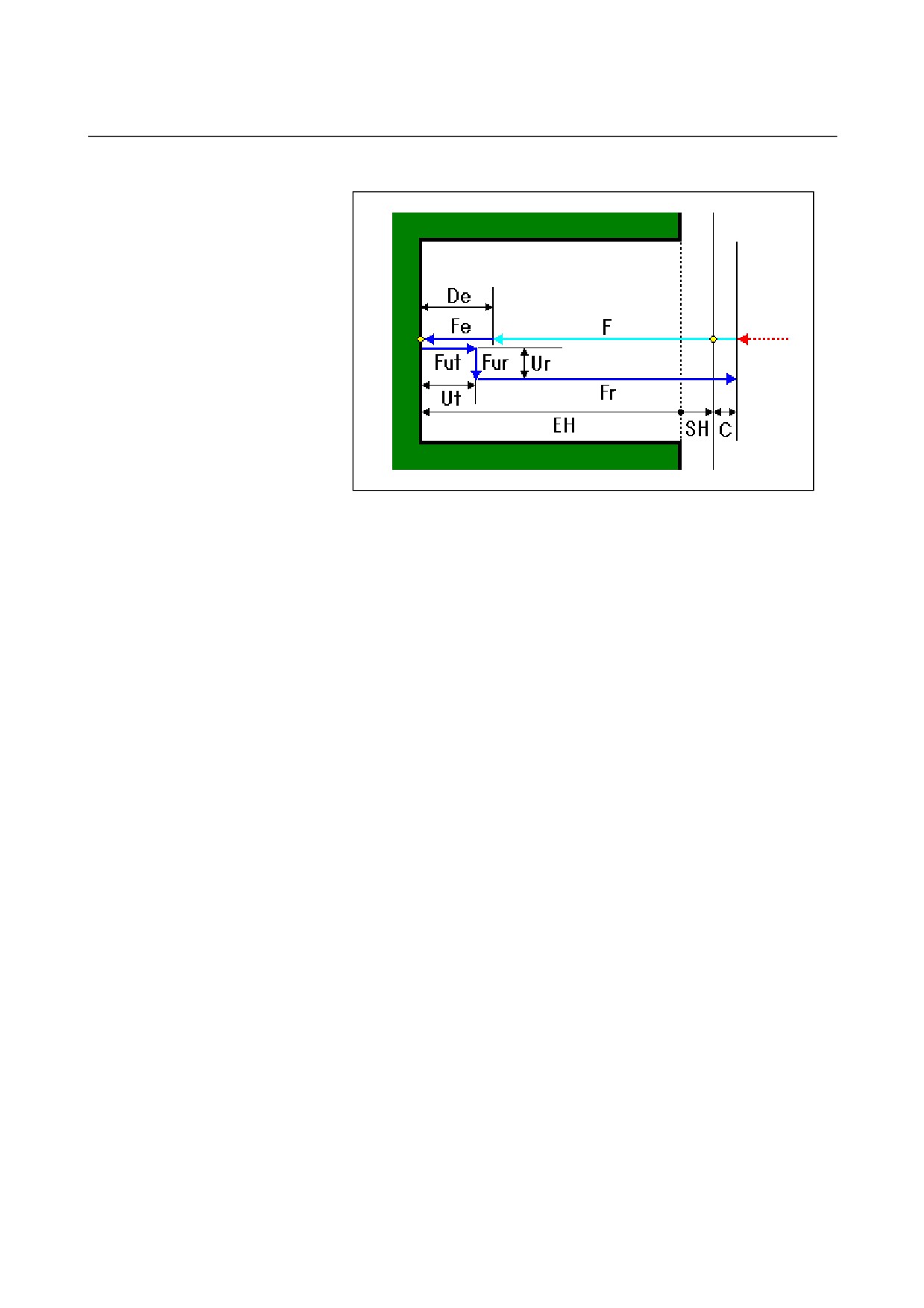
• Tool path
<1> Move the tool to the position "cutting start position + clearance
(C)" in rapid traverse.
<2> Move the tool to the cutting end position at the cutting feedrate
(F).
<3> The tool retracts to the position "cut end position + clearance
(Ut) along the tool axis" at the feedrate
(Fut) specified for
clearance along the tool axis.
<4> Spindle orientation is performed.
<5> The tool retracts to the position "current position + clearance
(Ur) in the tool radius direction" at the feedrate (Fur) specified
for clearance in the tool radius direction.
<6> Move the tool to the position "cutting start position + clearance
(C)" at the returning feedrate (Fr).
- 348 -
B-63874EN/05
CYCLE MACHINING TYPES
1.MILLING
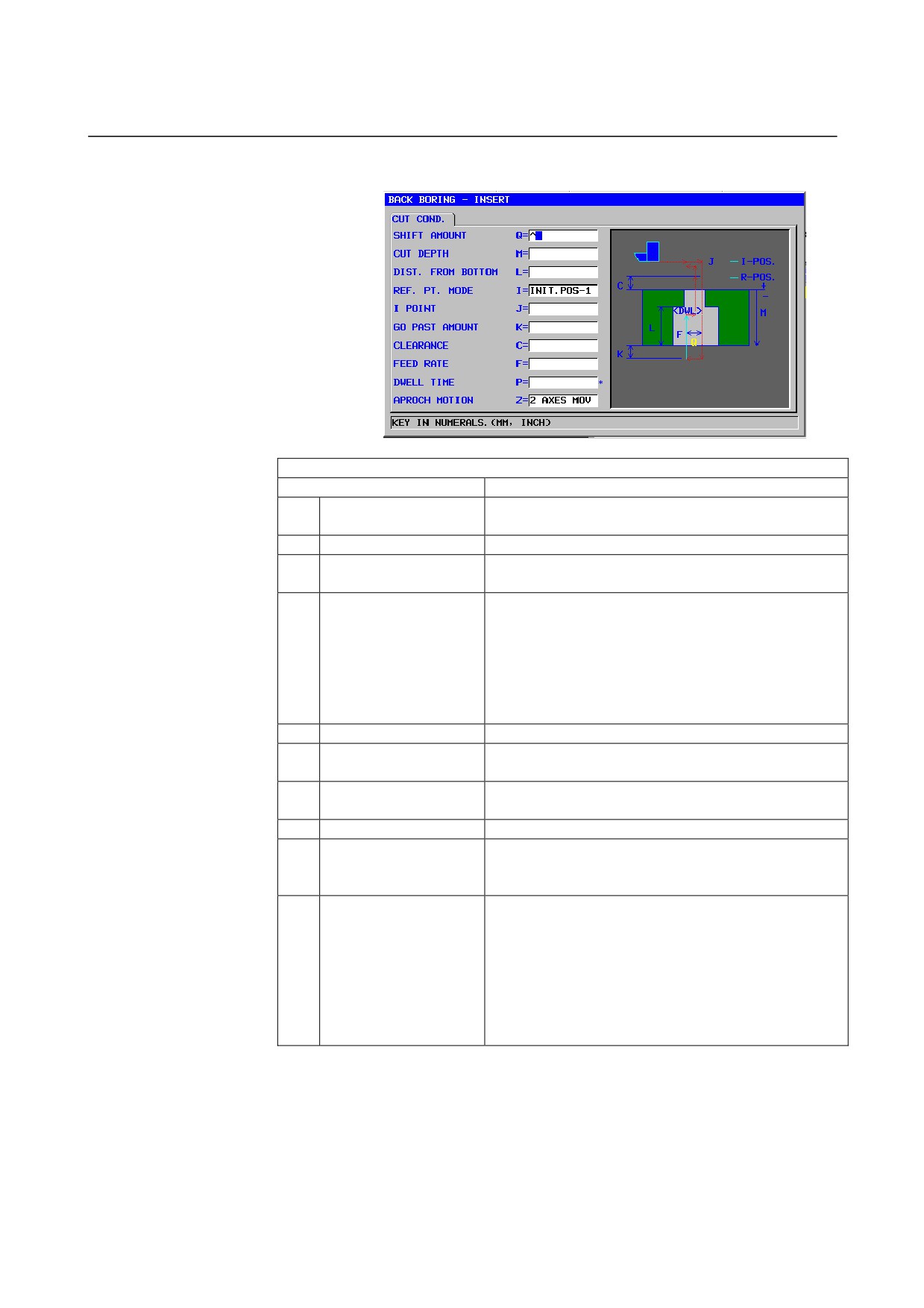
Back Boring: G1006
CUT COND.
Data item
Meaning
Q
SHIFT AMOUNT
Shift amount (radius value) at the hole bottom after
spindle orientation
(COPY)
M
CUT DEPTH
Cut depth (radius value, negative value)
L
DIST. FROM BOTTOM
Distance (radius value) at the hole bottom in the lifting
direction
I
REF.PT.MODE
[INIT-1] : An R position return is made in moving
between holes. Finally, a return is made to the
I point.
(initial value)
[INIT-2] : All movements between holes, including the
last return, are made as an I point return.
[REF.]
: All movements between holes, including the
last return, are made as an R position return.
J
I POINT
Coordinate of the I point
(COPY)
K*
GO PAST AMOUNT
Go-past amount at the hole bottom. If omitted, 0 is
assumed. (radius value, positive value)
(COPY)
C
CLEARANCE
Distance between the workpiece surface and R position
(radius value, positive value)
(COPY)
F
FEED RATE
Cutting feedrate (positive value)
(COPY)
P*
DWELL TIME
Dwell time at the hole bottom after lift machining. If
omitted, 0 is assumed. (units of seconds, positive value)
(COPY)
Z
APROCH MOTION
[2 AXES] : When moving from the current position to
the machining start point, the tool first
moves in the machining plane in two-axis
synchronous operation and then moves
along the tool axis. (initial value)
[3 AXES] : The tool moves from the current position to
the machining start point in three-axis
synchronous operation.
- 349 -
1.MILLING
CYCLE MACHINING TYPES
B-63874EN/05
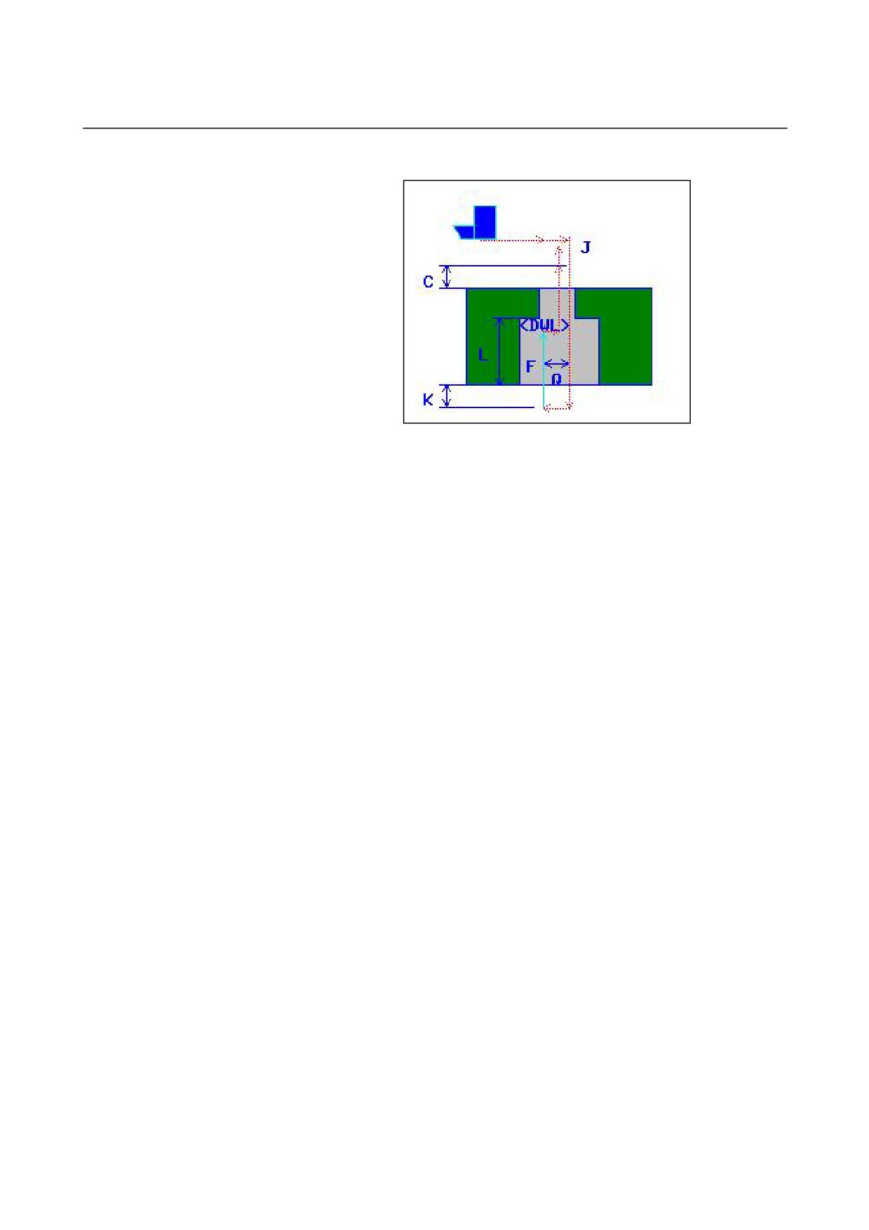
• Tool path
<1> Move the tool to the position "cutting start position + clearance
(C)" in rapid traverse.
<2> The tool is shifted away from the tool tip.
<3> The tool moves to the bottom of the hole (R point) by rapid
traverse.
<4> The tool returns by a shift amount toward the tool tip.
<5> The spindle is turned in the normal direction to cut in to the
position "K + L" along the tool axis at the feedrate (F) specified
for cut-in.
<6> The spindle is stopped.
<7> After being shifted away from the tool tip, the tool is pulled out
from the hole.
- 350 -
B-63874EN/05
CYCLE MACHINING TYPES
1.MILLING
1.1.2
Hole Position Block (XY Plane)
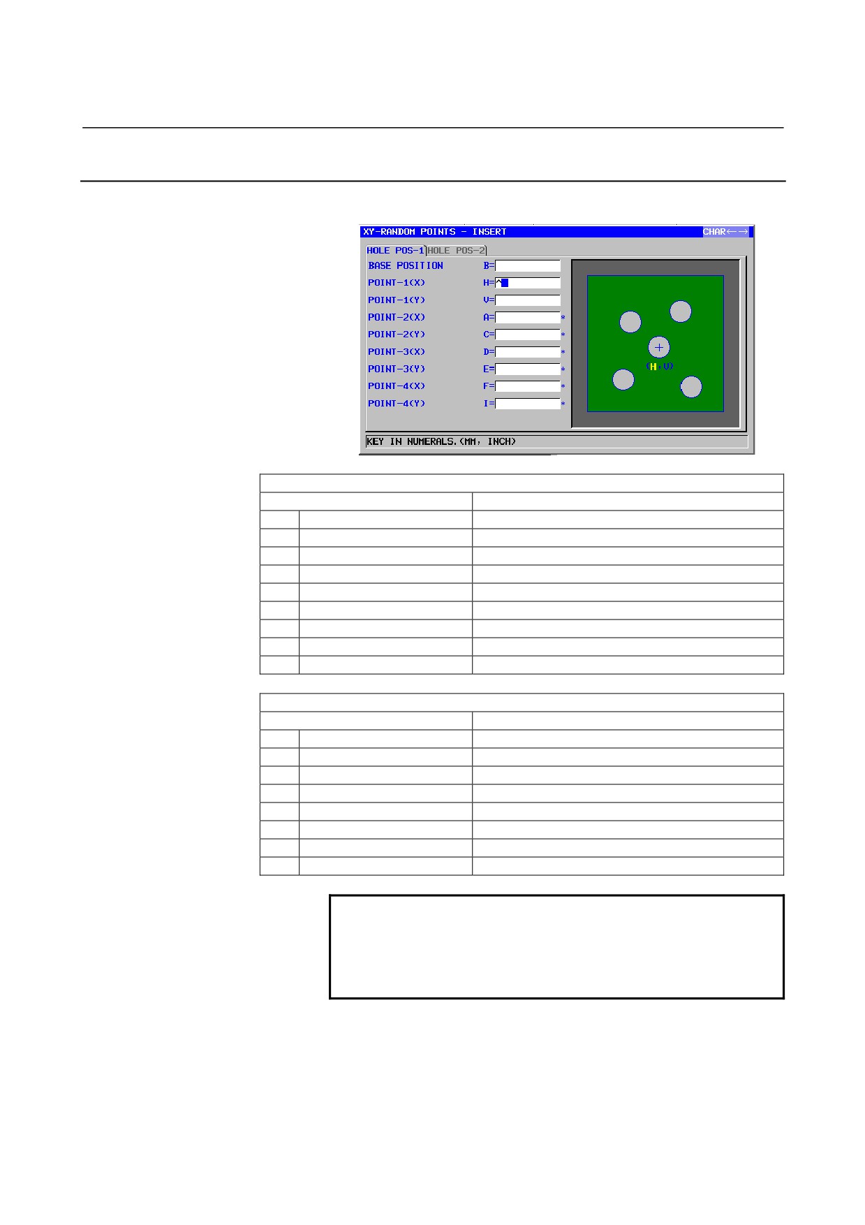
Random Points: G1210
HOLE POS-1
Data item
Meaning
B
BASE POSITION
Z coordinate of the workpiece surface
H
POINT-1 (X)
X coordinate of the first hole
V
POINT-1 (Y)
Y coordinate of the first hole
A*
POINT-2 (X)
X coordinate of the second hole
C*
POINT-2 (Y)
Y coordinate of the second hole
D*
POINT-3 (X)
X coordinate of the third hole
E*
POINT-3 (Y)
Y coordinate of the third hole
F*
POINT-4 (X)
X coordinate of the fourth hole
I*
POINT-4 (Y)
Y coordinate of the fourth hole
HOLE POS-2
Data item
Meaning
J*
POINT-5 (X)
X coordinate of the fifth hole
K*
POINT-5 (Y)
Y coordinate of the fifth hole
M*
POINT-6 (X)
X coordinate of the sixth hole
P*
POINT-6 (Y)
Y coordinate of the sixth hole
Q*
POINT-7 (X)
X coordinate of the seventh hole
R*
POINT-7 (Y)
Y coordinate of the seventh hole
S*
POINT-8 (X)
X coordinate of the eighth hole
T*
POINT-8 (Y)
Y coordinate of the eighth hole
NOTE
It is unnecessary to enter values for every hole
position. If entered, however, both X and Y
coordinates in a pair must be entered for a hole
position.
- 351 -
1.MILLING
CYCLE MACHINING TYPES
B-63874EN/05
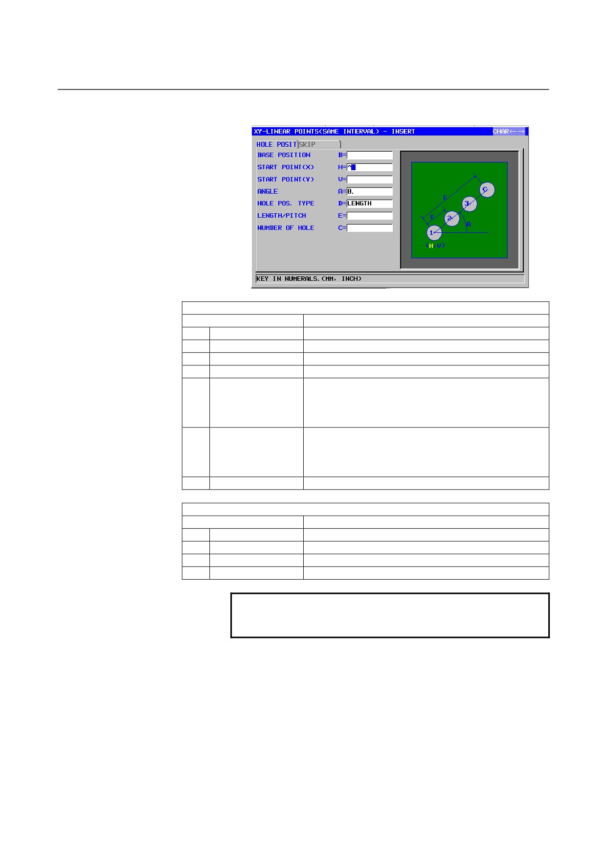
Linear Points (Same Interval): G1211
HOLE POSIT
Data item
Meaning
B
BASE POSITION
Z coordinate of the workpiece surface
H
START POINT (X)
X coordinate of the start point (first hole) of a straight line
V
START POINT (Y)
Y coordinate of the start point (first hole) of a straight line
A
ANGLE
Angle of a straight line from the X-axis (initial value = 0)
D
HOLE POS.TYPE
[LENGTH] : Specified with the distance between the first
and last holes, and the number of holes.
[PITCH]
: Specified with the distance between two
adjacent holes, and the number of holes.
E
LENGTH / PITCH
Length : Distance between the first and last holes
(if [LENGTH] is selected for item D)
Pitch
: Distance between two adjacent holes
(if [PITCH] is selected for item D)
C
NUMBER OF HOLE
Number of holes
SKIP
Data item
Meaning
F*
OMITTING POINT 1
Point where no hole is to be made (1)
I*
OMITTING POINT 2
Point where no hole is to be made (2)
J*
OMITTING POINT 3
Point where no hole is to be made (3)
K*
OMITTING POINT 4
Point where no hole is to be made (4)
NOTE
It is unnecessary to enter a value for any item of an
omitting point.
- 352 -
B-63874EN/05
CYCLE MACHINING TYPES
1.MILLING
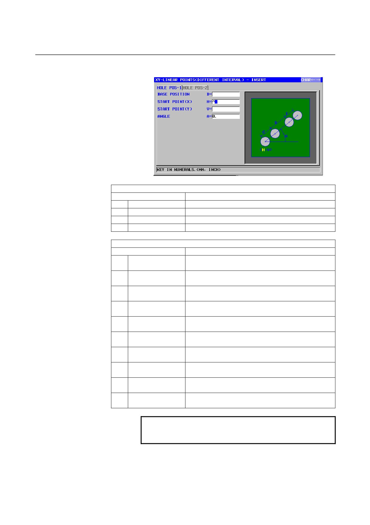
Linear Points (Different Interval): G1212
HOLE POS-1
Data item
Meaning
B
BASE POSITION
Z coordinate of the workpiece surface
H
START POINT (X)
X coordinate of the start point (first hole) of a straight line
V
START POINT (Y)
Y coordinate of the start point (first hole) of a straight line
A
ANGLE
Angle of a straight line from the X-axis (initial value = 0)
HOLE POS-2
Data item
Meaning
C
PITCH WIDTH-1
Distance between the first and second holes (positive or
negative value)
D
PITCH WIDTH-2
Distance between the second and third holes (positive or
negative value)
E*
PITCH WIDTH-3
Distance between the third and fourth holes (positive or
negative value)
F*
PITCH WIDTH-4
Distance between the fourth and fifth holes (positive or
negative value)
I*
PITCH WIDTH-5
Distance between the fifth and sixth holes (positive or
negative value)
J*
PITCH WIDTH-6
Distance between the sixth and seventh holes (positive or
negative value)
K*
PITCH WIDTH-7
Distance between the seventh and eighth holes (positive
or negative value)
M*
PITCH WIDTH-8
Distance between the eighth and ninth holes (positive or
negative value)
P*
PITCH WIDTH-9
Distance between the ninth and tenth holes (positive or
negative value)
Q*
PITCH WIDTH-10
Distance between the tenth and eleventh holes (positive
or negative value)
NOTE
It is unnecessary to enter a value for every pitch
width data item.
- 353 -
1.MILLING
CYCLE MACHINING TYPES
B-63874EN/05
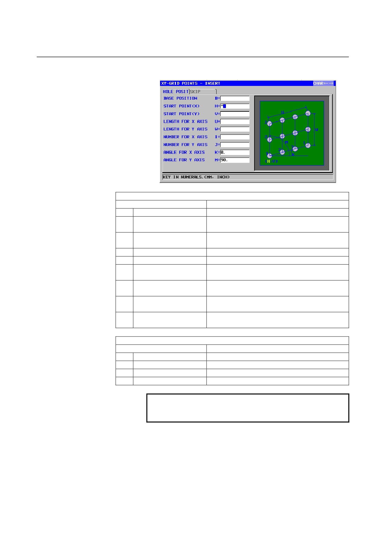
Grid Points: G1213
HOLE POSIT
Data item
Meaning
B
BASE POSITION
Z coordinate of the workpiece surface
H
START POINT (X)
X coordinate of the start point (first hole) of a straight
line
V
START POINT (Y)
Y coordinate of the start point (first hole) of a straight
line
U
LENGTH FOR X AXIS
Length of the first side of a grid (positive value)
W
LENGTH FOR Y AXIS
Length of the second side of a grid (positive value)
I
NUMBER FOR X AXIS
Number of holes on the first side of a grid (positive
value)
J
NUMBER FOR Y AXIS
Number of holes on the second side of a grid
(positive value)
K
ANGLE FOR X AXIS
Angle of the first side of a grid from the X-axis
(initial value = 0)
M
ANGLE FOR Y AXIS
Angle of the second side of a grid from the X-axis
(initial value = 90)
SKIP
Data item
Meaning
A*
OMITTING POINT 1
Point where no hole is to be made (1)
C*
OMITTING POINT 2
Point where no hole is to be made (2)
D*
OMITTING POINT 3
Point where no hole is to be made (3)
E*
OMITTING POINT 4
Point where no hole is to be made (4)
NOTE
It is unnecessary to enter a value for any item of an
omitting point.
- 354 -
B-63874EN/05
CYCLE MACHINING TYPES
1.MILLING
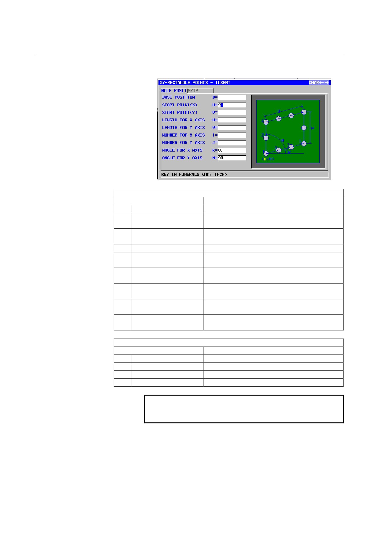
Rectangle Points: G1214
HOLE POSIT
Data item
Meaning
B
BASE POSITION
Z coordinate of the workpiece surface
H
START POINT (X)
X coordinate of the start point (first hole) of a straight
line
V
START POINT (Y)
Y coordinate of the start point (first hole) of a straight
line
U
LENGTH FOR X AXIS
Length of the first side of a rectangle (positive value)
W
LENGTH FOR Y AXIS
Length of the second side of a rectangle (positive
value)
I
NUMBER FOR X AXIS
Number of holes on the first side of a rectangle
(positive value)
J
NUMBER FOR Y AXIS
Number of holes on the second side of a rectangle
(positive value)
K
ANGLE FOR X AXIS
Angle of the first side of a rectangle from the X-axis
(initial value = 0)
M
ANGLE FOR Y AXIS
Angle of the second side of a rectangle from the
X-axis (initial value = 90)
SKIP
Data item
Meaning
A*
OMITTING POINT 1
Point where no hole is to be made (1)
C*
OMITTING POINT 2
Point where no hole is to be made (2)
D*
OMITTING POINT 3
Point where no hole is to be made (3)
E*
OMITTING POINT 4
Point where no hole is to be made (4)
NOTE
It is unnecessary to enter a value for any item of an
omitting point.
- 355 -
1.MILLING
CYCLE MACHINING TYPES
B-63874EN/05
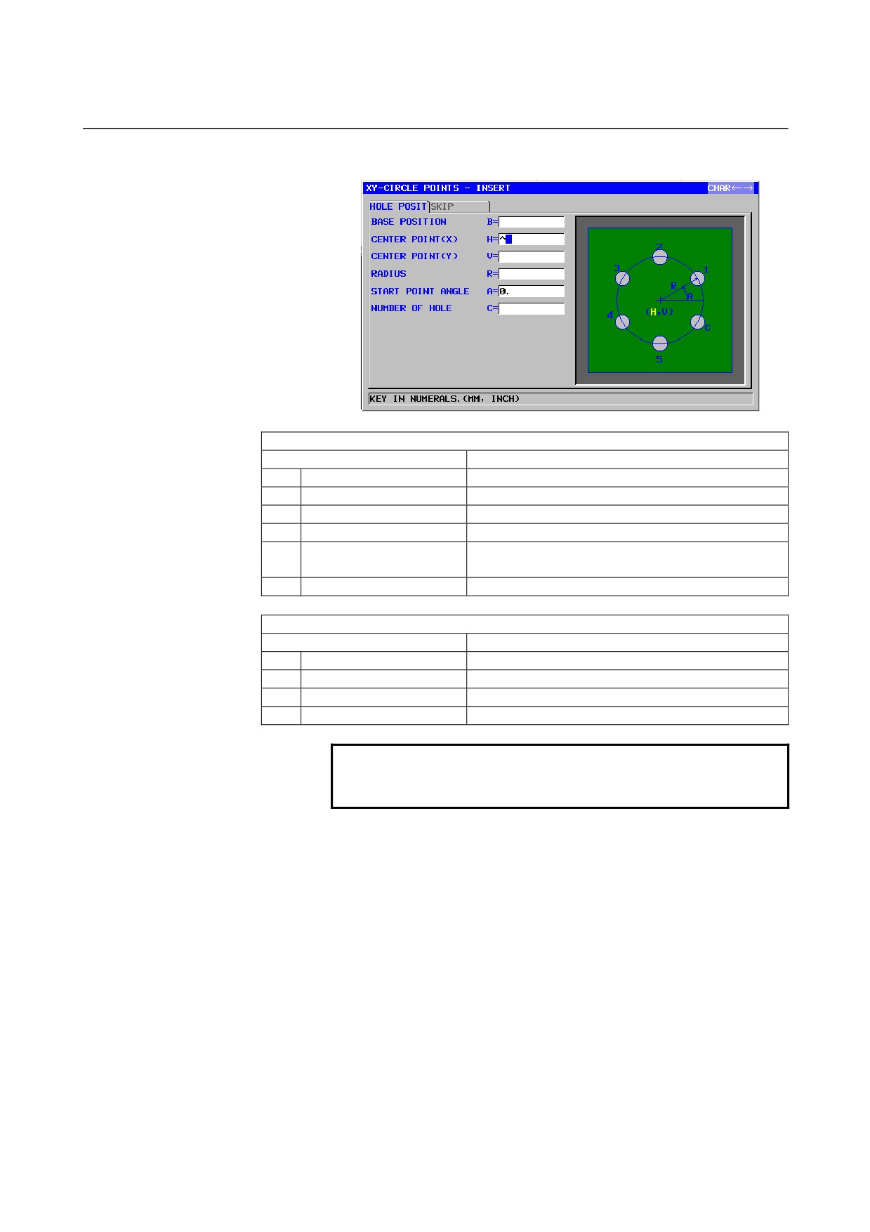
Circle Points: G1215
HOLE POINTS
Data item
Meaning
B
BASE POSITION
Z coordinate of the workpiece surface
H
CENTER POINT (X)
X coordinate of the center of a circle
V
CENTER POINT (Y)
Y coordinate of the center of a circle
R
RADIUS
Radius of a circle (positive value)
A
START POINT ANGLE
Central angle of the first hole from the X-axis
(positive or negative value)
(initial value = 0)
C
NUMBER OF HOLE
Number of holes to be made (positive value)
SKIP
Data item
Meaning
D*
OMITTING POINT 1
Point where no hole is to be made (1)
E*
OMITTING POINT 2
Point where no hole is to be made (2)
F*
OMITTING POINT 3
Point where no hole is to be made (3)
I*
OMITTING POINT 4
Point where no hole is to be made (4)
NOTE
It is unnecessary to enter a value for any item of an
omitting point.
- 356 -
B-63874EN/05
CYCLE MACHINING TYPES
1.MILLING
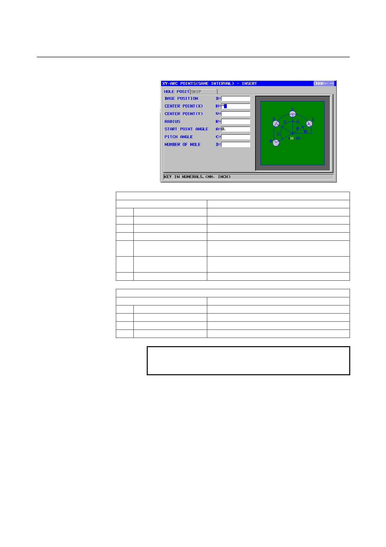
Arc Points (Same Interval): G1216
HOLE POSIT
Data item
Meaning
B
BASE POSITION
Z coordinate of the workpiece surface
H
CENTER POINT (X)
X coordinate of the center of an arc
V
CENTER POINT (Y)
Y coordinate of the center of an arc
R
RADIUS
Radius of an arc (positive value)
A
START POINT ANGLE
Central angle of the first hole from the X-axis
(positive or negative value) (initial value = 0)
C
PITCH ANGLE
Central angle between two adjacent holes (positive
or negative value)
D
NUMBER OF HOLE
Number of holes to be made (positive value)
SKIP
Data item
Meaning
E*
OMITTING POINT 1
Point where no hole is to be made (1)
F*
OMITTING POINT 2
Point where no hole is to be made (2)
I*
OMITTING POINT 3
Point where no hole is to be made (3)
J*
OMITTING POINT 4
Point where no hole is to be made (4)
NOTE
It is unnecessary to enter a value for any item of an
omitting point.
- 357 -
1.MILLING
CYCLE MACHINING TYPES
B-63874EN/05
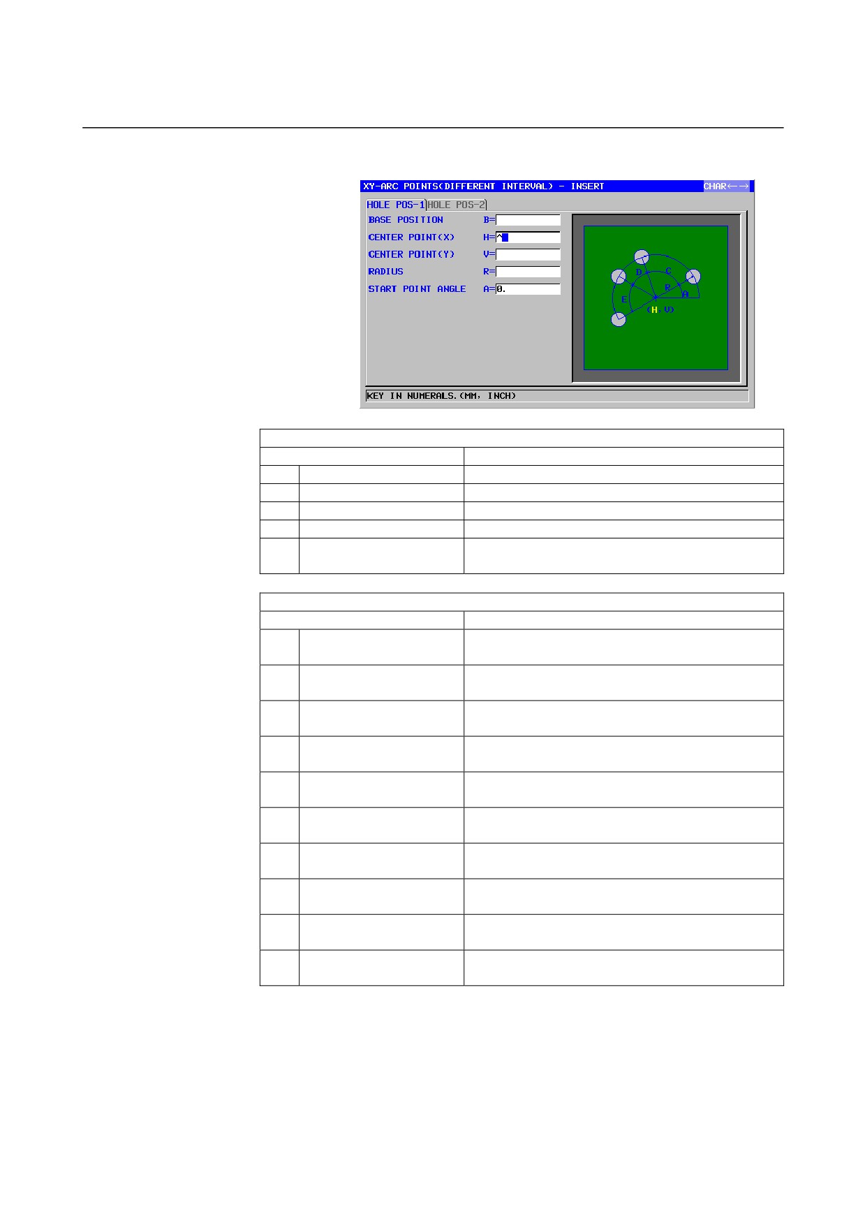
Arc Points (Different Interval): G1217
HOLE POS-1
Data item
Meaning
B
BASE POSITION
Z coordinate of the workpiece surface
H
CENTER POINT (X)
X coordinate of the center of an arc
V
CENTER POINT (Y)
Y coordinate of the center of an arc
R
RADIUS
Radius of an arc (positive value)
A
START POINT ANGLE
Central angle of the first hole from the X-axis
(positive or negative value) (initial value = 0)
HOLE POS-2
Data item
Meaning
C*
PITCH ANGLE-1
Central angle between the first and second holes
(positive or negative value)
D*
PITCH ANGLE-2
Central angle between the second and third holes
(positive or negative value)
E*
PITCH ANGLE-3
Central angle between the third and fourth holes
(positive or negative value)
F*
PITCH ANGLE-4
Central angle between the fourth and fifth holes
(positive or negative value)
I*
PITCH ANGLE-5
Central angle between the fifth and sixth holes
(positive or negative value)
J*
PITCH ANGLE-6
Central angle between the sixth and seventh holes
(positive or negative value)
K*
PITCH ANGLE-7
Central angle between the seventh and eighth holes
(positive or negative value)
M*
PITCH ANGLE-8
Central angle between the eighth and ninth holes
(positive or negative value)
P*
PITCH ANGLE-9
Central angle between the ninth and tenth holes
(positive or negative value)
Q*
PITCH ANGLE-10
Central angle between the tenth and eleventh holes
(positive or negative value)
- 358 -
B-63874EN/05
CYCLE MACHINING TYPES
1.MILLING
1.1.3
Hole Position Block (YZ Plane)
The same hole position block types as for the XY plane explained in the
previous subsection are available for the YZ plane. They are provided
with the following G codes.
The data to be set for the YZ plane is the same as for the XY plane except
that the XY plane is changed to the YZ plane and that the direction in
which the tool moves to cut is changed from the Z-axis to the X-axis.
Random Points
: G1310
Linear Points (Same Interval)
: G1311
Linear Points (Different Interval)
: G1312
Grid Points
: G1313
Rectangle Points
: G1314
Circle Points
: G1315
Arc Points (Same Interval)
: G1316
Arc Points (Different Interval)
: G1317
- 359 -
1.MILLING
CYCLE MACHINING TYPES
B-63874EN/05
1.1.4
Hole Position Block (XC Plane and End Face)
A menu for selecting a hole position block in which the C-axis is used in
making holes is displayed by selecting the "C-axis Figure" tab from the
milling figure menu, using the ← and → cursor keys.
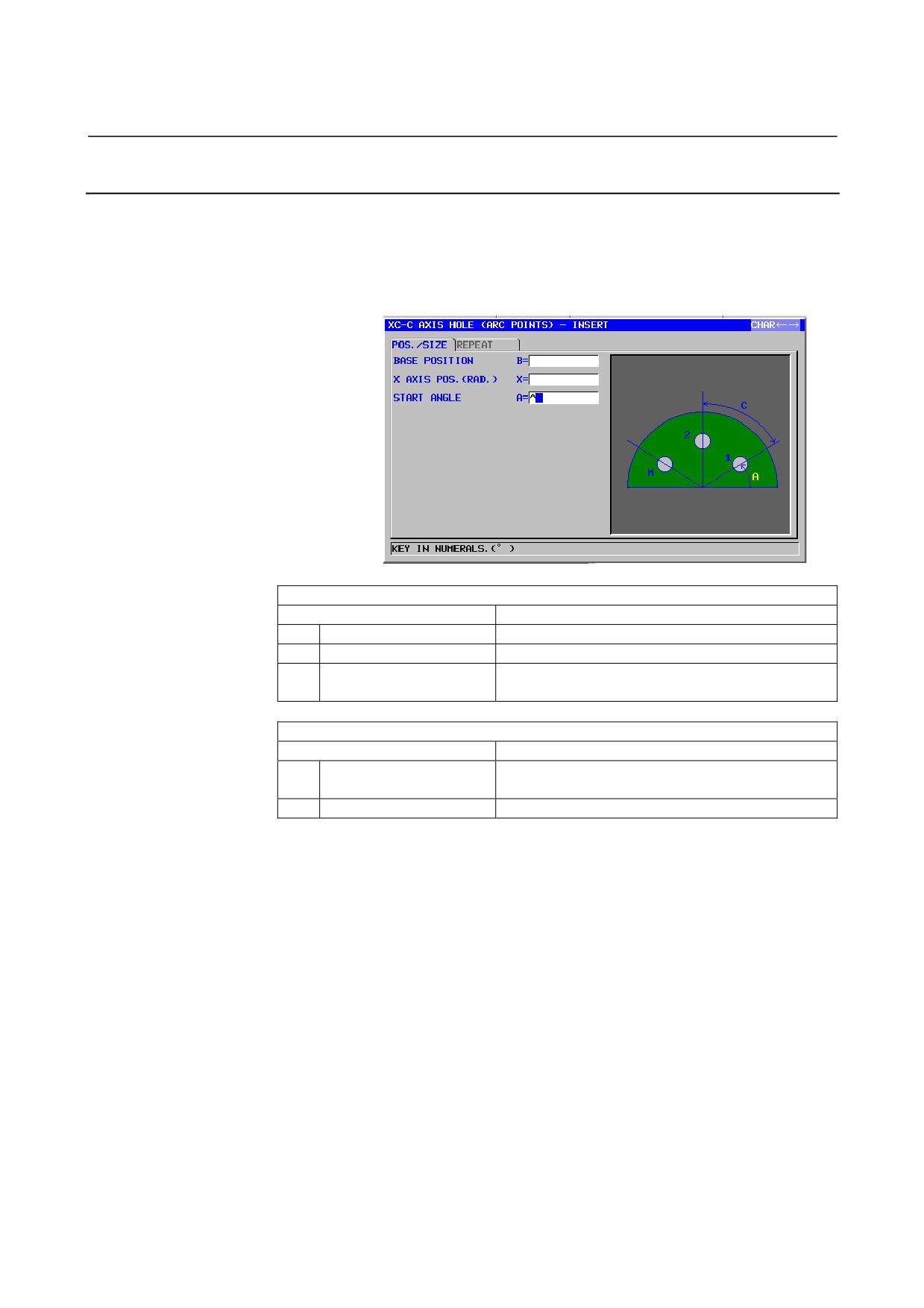
C Axis Hole on Face (Circle Points): G1572
POS / SIZE
Data item
Meaning
B
BASE POSITION
Z coordinate of the workpiece surface
X
X AXIS POS.(RAD.)
X coordinate of a hole position (common to all holes)
A
START ANGLE
Central angle of the first hole form the C0 axis
(positive or negative value)
REPEAT
Data item
Meaning
C
PITCH ANGLE
Amount of movement between two holes along the
C-axis (positive or negative value)
M
NUMBER OF HOLE
Number of holes to be made (positive value)
- 360 -
B-63874EN/05
CYCLE MACHINING TYPES
1.MILLING
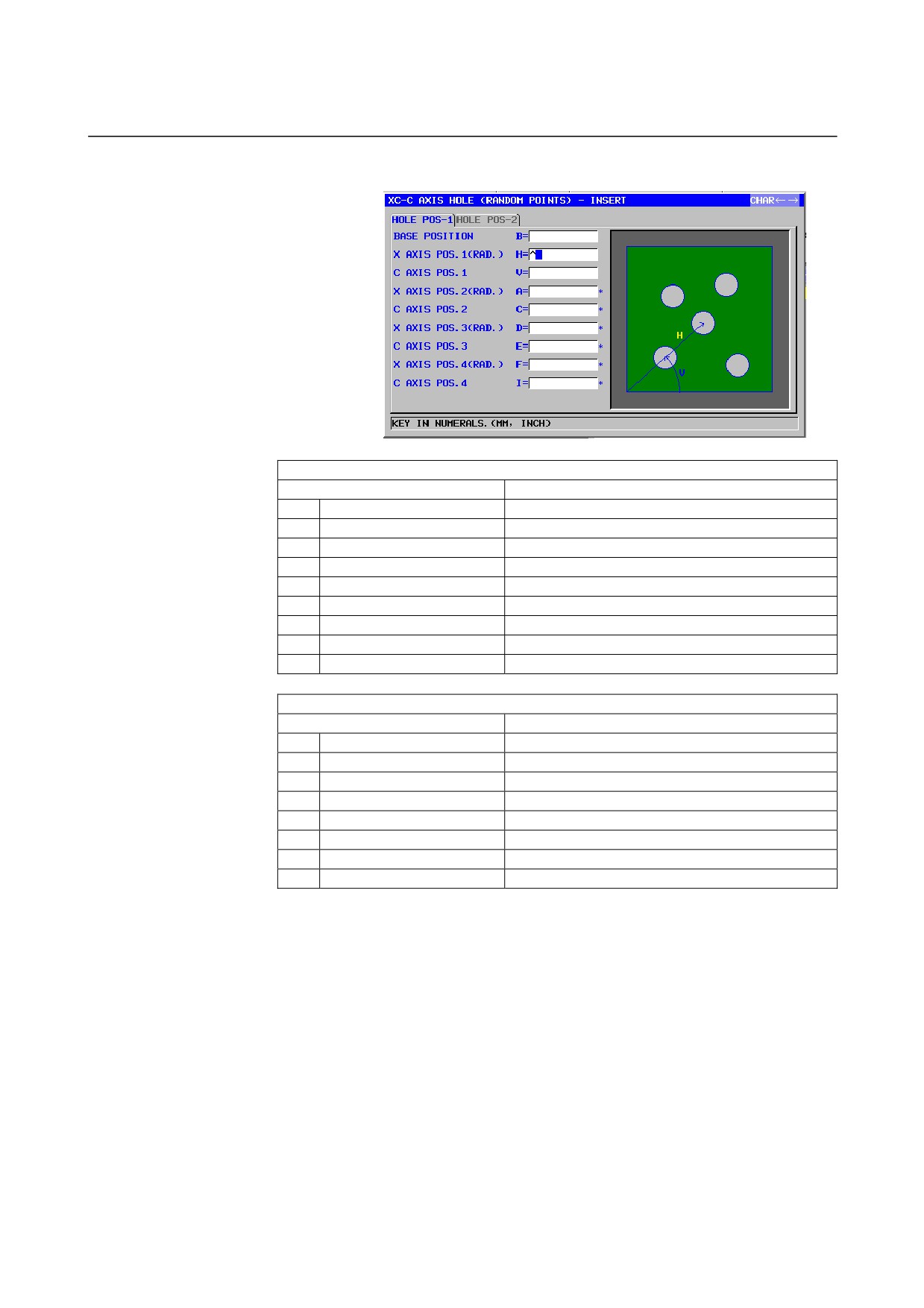
C Axis Hole on Face (Random Points): G1573
HOLE POS-1
Data item
Meaning
B
BASE POSITION
Z coordinate of the workpiece surface
H
X AXIS POS.1(RAD.)
X coordinate of the first hole (radius value)
V
C AXIS POS.1
C coordinate of the first hole
A*
X AXIS POS.2(RAD.)
X coordinate of the second hole (radius value)
C*
C AXIS POS.2
C coordinate of the second hole
D*
X AXIS POS.3(RAD.)
X coordinate of the third hole (radius value)
E*
C AXIS POS.3
C coordinate of the third hole
F*
X AXIS POS.4(RAD.)
X coordinate of the fourth hole (radius value)
I*
C AXIS POS.4
C coordinate of the fourth hole
HOLE POS-2
Data item
Meaning
J*
X AXIS POS.5(RAD.)
X coordinate of the fifth hole (radius value)
K*
C AXIS POS.5
C coordinate of the fifth hole
M*
X AXIS POS.6(RAD.)
X coordinate of the sixth hole (radius value)
P*
C AXIS POS.6
C coordinate of the sixth hole
Q*
X AXIS POS.7(RAD.)
X coordinate of the seventh hole (radius value)
R*
C AXIS POS.7
C coordinate of the seventh hole
S*
X AXIS POS.8(RAD.)
X coordinate of the eighth hole (radius value)
T*
C AXIS POS.8
C coordinate of the eighth hole
- 361 -
1.MILLING
CYCLE MACHINING TYPES
B-63874EN/05
1.1.5
Hole Position Block (ZC Plane and Cylindrical Surface)
The same hole position block types as for the XC plane explained in the
previous subsection are available for the ZC plane. They are provided
with the following G codes.
The data to be set for the ZC plane is the same as for the XC plane except
that the XC plane (blank end face) is changed to the ZC plane (blank
cylindrical surface) and that the direction in which the tool moves to cut
is changed from the Z-axis to the X-axis.
Holes on a cylindrical surface (ZC) figure along the C-axis -
Circle Points: G1672
Holes on a cylindrical surface (ZC) figure along the C-axis -
Random Points: G1673
1.1.6
Hole Position Block (XA Plane and Cylindrical Surface)
The same hole position block types as for the ZC plane explained in the
previous subsection are available for the XA plane. They are provided
with the following G codes.
The data to be set for the XA plane is the same as for the ZC plane except
that the ZC plane (blank end face) is changed to the XA plane (blank
cylindrical surface) and that the direction in which the tool moves to cut
is changed from the X-axis to the Z-axis.
Holes on a cylindrical surface (XA) figure along the A-axis -
Circle Points: G1772
Holes on a cylindrical surface (XA) figure along the A-axis -
Random Points: G1773
NOTE
The following parameter setting is necessary to
execute XA plane cycle.
• No.27003#2=1, 27003#1=0 and 27003#0=0
- 362 -
B-63874EN/05
CYCLE MACHINING TYPES
1.MILLING
1.2
HOLE MACHINING BY TURNING (WITH THE TOOL
ROTATED)
1.2.1
Machining Type Blocks for Hole Machining by Turning (with
the Tool Rotated)
NOTE
1 Hole machining by turning (with the tool rotated) is
enabled when bit 1 of parameter No. 27000 = 1.
2 The hole position blocks for hole machining by
turning (with the tool rotated) are the same as
those for hole machining by milling. See the
previous section (Hole Position Block).
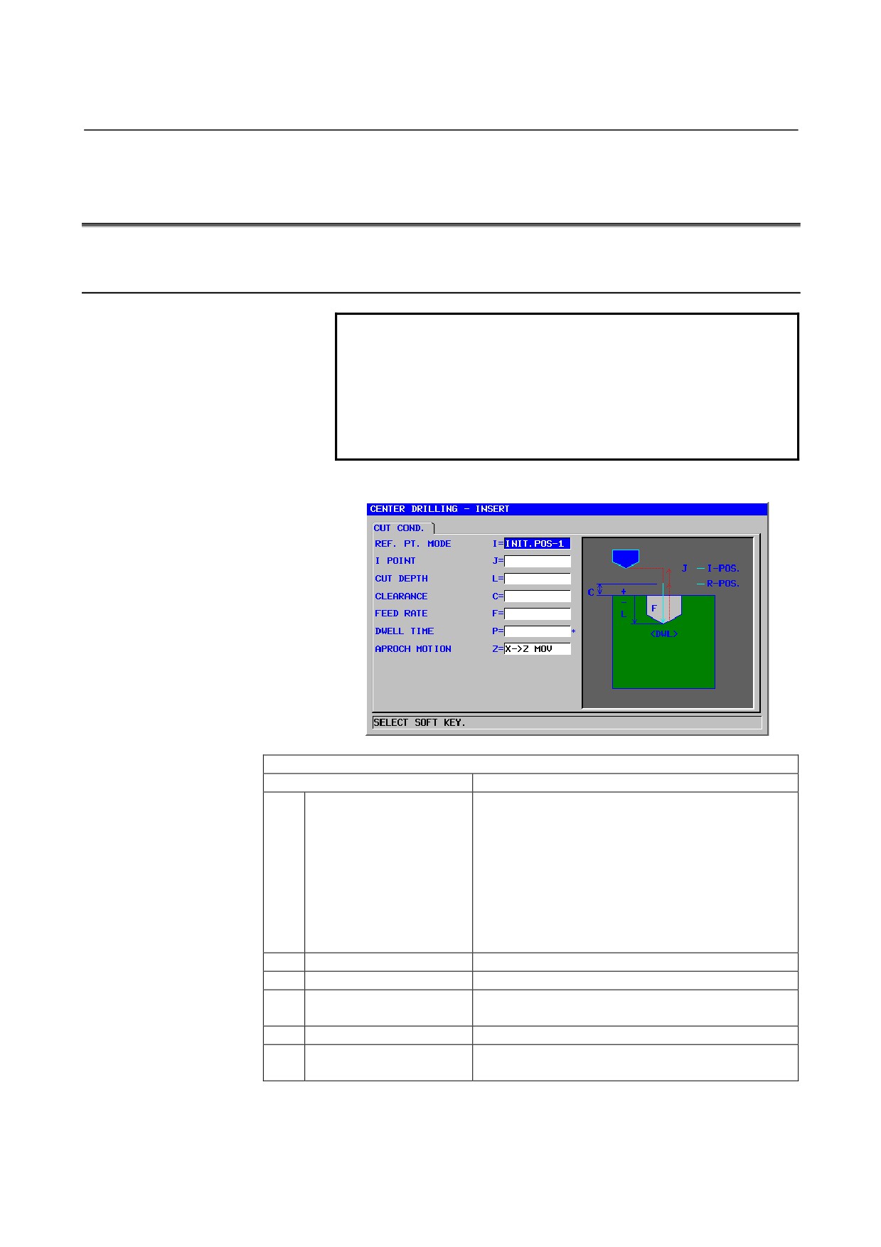
Center drilling: G1110
Cutting condition
Data item
Meaning
I
REF.PT.MODE
[INIT-1] : An R position return is made in moving
between holes. Finally, a return is made to
the I point.
(initial value)
[INITI-2]: All movements between holes, including
the last return, are made as an I point
return.
[REF.]
: All movements between holes, including
the last return, are made as an R position
return.
J
I POINT
Coordinate of the I point
(COPY)
L
CUT DEPTH
Cut depth (radius value, negative value)
C
CLEARANCE
Distance between the workpiece surface and R
position (radius value, positive value)
(COPY)
F
FEED RATE
Cutting feedrate (positive value)
(COPY)
P*
DWELL TIME
Dwell time at the hole bottom (units of seconds,
positive value).
(COPY)
- 363 -

1.MILLING
CYCLE MACHINING TYPES
B-63874EN/05
Cutting condition
Data item
Meaning
Z
APROCH MOTION
[Z→X]
: From the current position to the
machining start point, the tool moves in
the Z-axis direction and then in the
X-axis direction.
[X→Z]
: From the current position to the
machining start point, the tool moves in
the Z-axis direction and then in the
X-axis direction. (initial value)
[2 AXES] : From the current position to the
machining start point, the tool moves
simultaneously in the X- and Z-axis
directions.
- 364 -
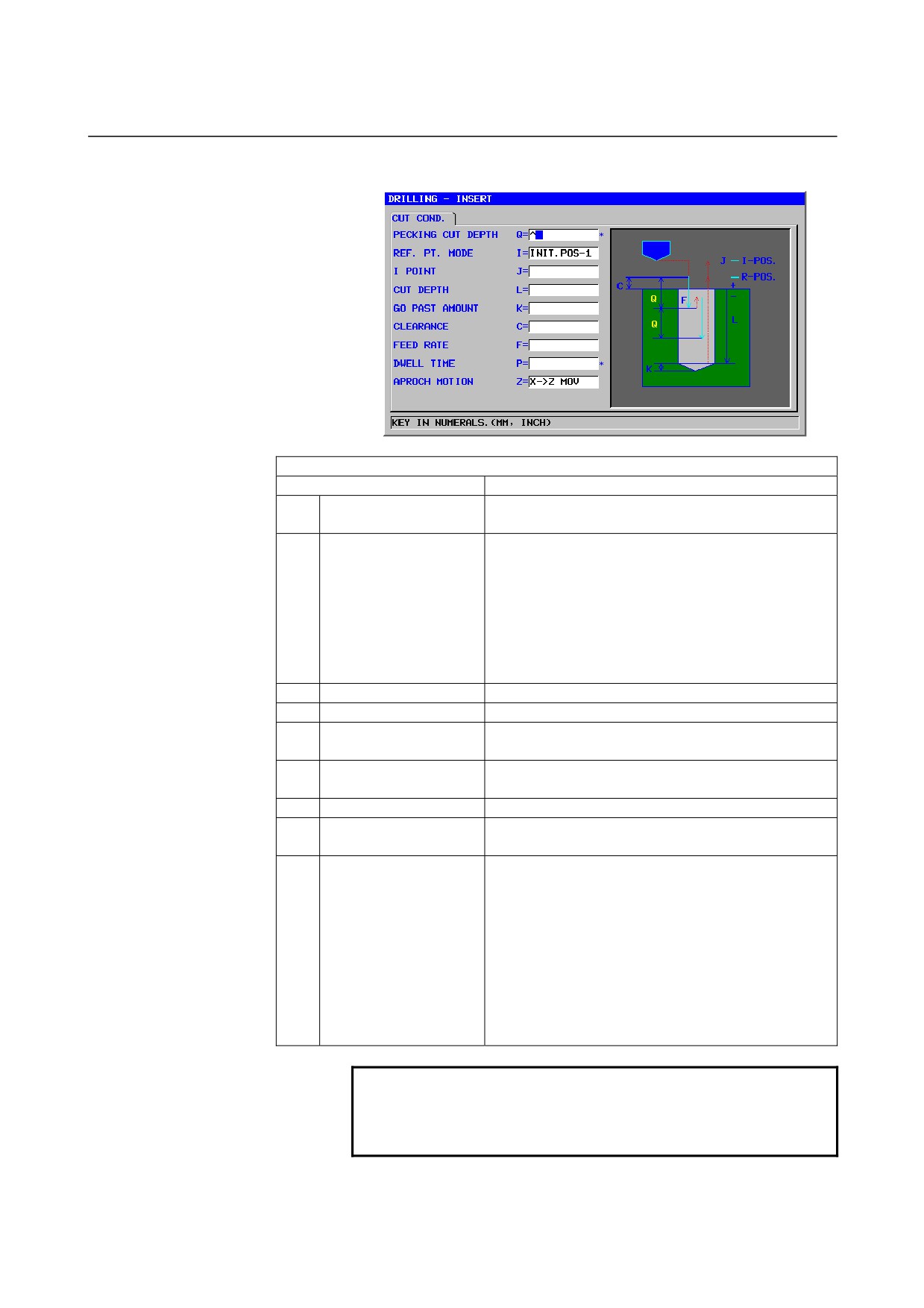
B-63874EN/05
CYCLE MACHINING TYPES
1.MILLING
Drilling: G1111
Cutting condition
Data item
Meaning
Q*
PECKING CUT DEPTH
Depth of cut made by one cut (radius value, positive
value)
(COPY)
(Note)
I
REF.PT.MODE
[INIT-1] : An R position return is made in moving
between holes. Finally, a return is made to
the I point.
(initial value)
[INIT-2] : All movements between holes, including the
last return, are made as an I point return.
[REF.]
: All movements between holes, including the
last return, are made as an R position
return.
J
I POINT
Coordinate of the I point
(COPY)
L
CUT DEPTH
Cut depth (radius value, negative value)
K
GO PAST AMOUNT
Length of the incomplete hole portion at the tool tip
(radius value, positive value)
(COPY)
C
CLEARANCE
Distance between the workpiece surface and R
position (radius value, positive value)
(COPY)
F
FEED RATE
Cutting feedrate (positive value)
(COPY)
P*
DWELL TIME
Dwell time at the hole bottom (units of seconds,
positive value).
(COPY)
Z
APROCH MOTION
[Z→X]
: From the current position to the machining
start point, the tool moves in the Z-axis
direction and then in the X-axis direction.
[X→Z]
: From the current position to the machining
start point, the tool moves in the Z-axis
direction and then in the X-axis direction.
(initial value)
[2 AXES] : From the current position to the machining
start point, the tool moves simultaneously
in the X- and Z-axis directions.
NOTE
The system refers to the parameter No.5114 as the
return amount. Therefore, please set No.5114 to
suitable value before machining.
- 365 -
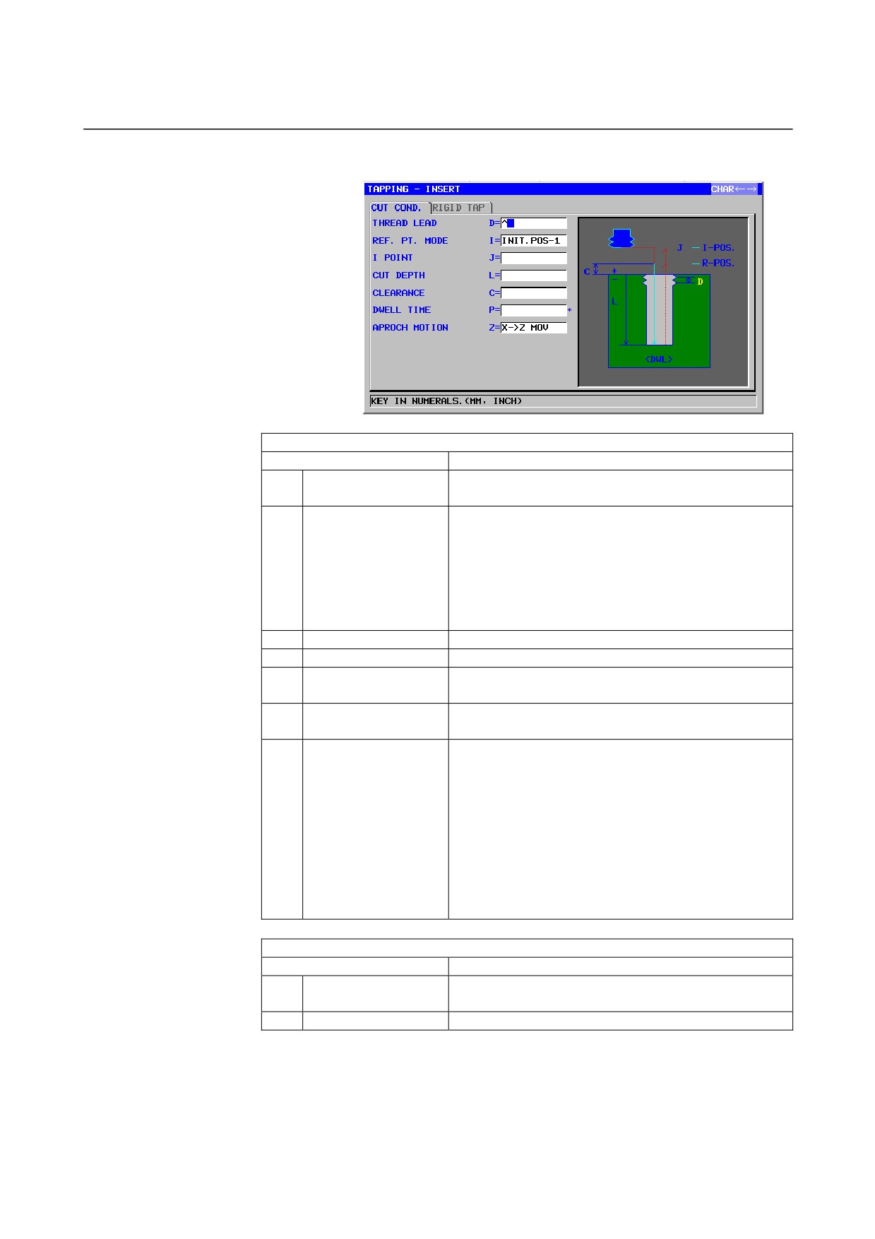
1.MILLING
CYCLE MACHINING TYPES
B-63874EN/05
Tapping: G1112
Cutting condition
Data item
Meaning
D
THREAD LEAD
Tapping tool lead (radius value, positive value)
(COPY)
I
REF.PT.MODE
[INIT-1] : An R position return is made in moving
between holes. Finally, a return is made to the
I point.
(initial value)
[INIT-2] : All movements between holes, including the
last return, are made as an I point return.
[REF.]
: All movements between holes, including the
last return, are made as an R position return.
J
I POINT
Coordinate of the I point
(COPY)
L
CUT DEPTH
Cut depth (radius value, negative value)
C
CLEARANCE
Distance between the workpiece surface and R position
(radius value, positive value)
(COPY)
P*
DWELL TIME
Dwell time at the hole bottom (units of seconds, positive
value).
(COPY)
Z
APROCH MOTION
[Z→X]
: From the current position to the machining
start point, the tool moves in the Z-axis
direction and then in the X-axis direction.
[X→Z]
: From the current position to the machining
start point, the tool moves in the Z-axis
direction and then in the X-axis direction.
(initial value)
[2 AXES] : From the current position to the machining
start point, the tool moves simultaneously in
the X- and Z-axis directions.
Rigid tapping
Data item
Meaning
R
TAP TYPE
[FLOAT]
: Specifies the float tapping. (initial value)
[RIGID]
: Specifies the rigid tapping.
S
SPINDLE SPEED
Spindle speed (min-1) (Note)
- 366 -
B-63874EN/05
CYCLE MACHINING TYPES
1.MILLING
NOTE
1 When you use rigid tapping mode M code
command (No.5200#0=0), the system refers to
No.5210 or No.5212 as the value of M code.
Therefore, please set No.5210 or No.5212 to
suitable value before machining.
- 367 -
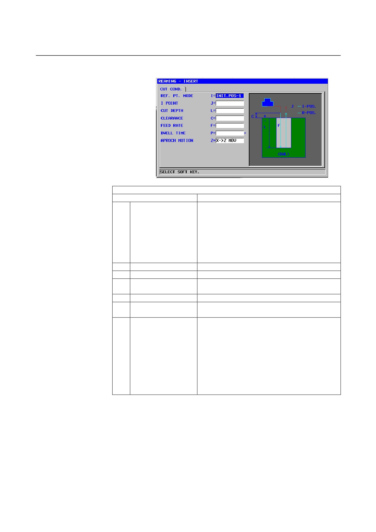
1.MILLING
CYCLE MACHINING TYPES
B-63874EN/05
Reaming: G1113
Cutting condition
Data item
Meaning
I
REF.PT.MODE
[INIT-1] : An R position return is made in moving
between holes. Finally, a return is made to
the I point.
(initial value)
[INIT-2] : All movements between holes, including the
last return, are made as an I point return.
[REF.]
: All movements between holes, including the
last return, are made as an R position
return.
J
I POINT
Coordinate of the I point
(COPY)
L
CUT DEPTH
Cut depth (radius value, negative value)
C
CLEARANCE
Distance between the workpiece surface and R
position (radius value, positive value)
(COPY)
F
FEED RATE
Cutting feedrate (positive value)
(COPY)
P*
DWELL TIME
Dwell time at the hole bottom (units of seconds,
positive value).
(COPY)
Z
APROCH MOTION
[Z→X]
: From the current position to the machining
start point, the tool moves in the Z-axis
direction and then in the X-axis direction.
[X→Z]
: From the current position to the machining
start point, the tool moves in the Z-axis
direction and then in the X-axis direction.
(initial value)
[2 AXES] : From the current position to the machining
start point, the tool moves simultaneously
in the X- and Z-axis directions.
- 368 -
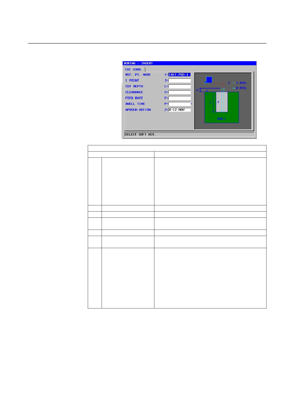
B-63874EN/05
CYCLE MACHINING TYPES
1.MILLING
Boring: G1114
Cutting condition
Data item
Meaning
I
REF.PT.MODE
[INIT-1] : An R position return is made in moving
between holes. Finally, a return is made to
the I point.
(initial value)
[INIT-2] : All movements between holes, including the
last return, are made as an I point return.
[REF.]
: All movements between holes, including the
last return, are made as an R position
return.
J
I POINT
Coordinate of the I point
(COPY)
L
CUT DEPTH
Cut depth (radius value, negative value)
C
CLEARANCE
Distance between the workpiece surface and R
position (radius value, positive value)
F
FEED RATE
Cutting feedrate (positive value)
(COPY)
P*
DWELL TIME
Dwell time at the hole bottom (units of seconds,
positive value).
(COPY)
Z
APROCH MOTION
[Z→X]
: From the current position to the machining
start point, the tool moves in the Z-axis
direction and then in the X-axis direction.
[X→Z]
: From the current position to the machining
start point, the tool moves in the Z-axis
direction and then in the X-axis direction.
(initial value)
[2 AXES] : From the current position to the machining
start point, the tool moves simultaneously
in the X- and Z-axis directions.
- 369 -
1.MILLING
CYCLE MACHINING TYPES
B-63874EN/05
1.3
FACING
1.3.1
Machining Type Blocks for Facing
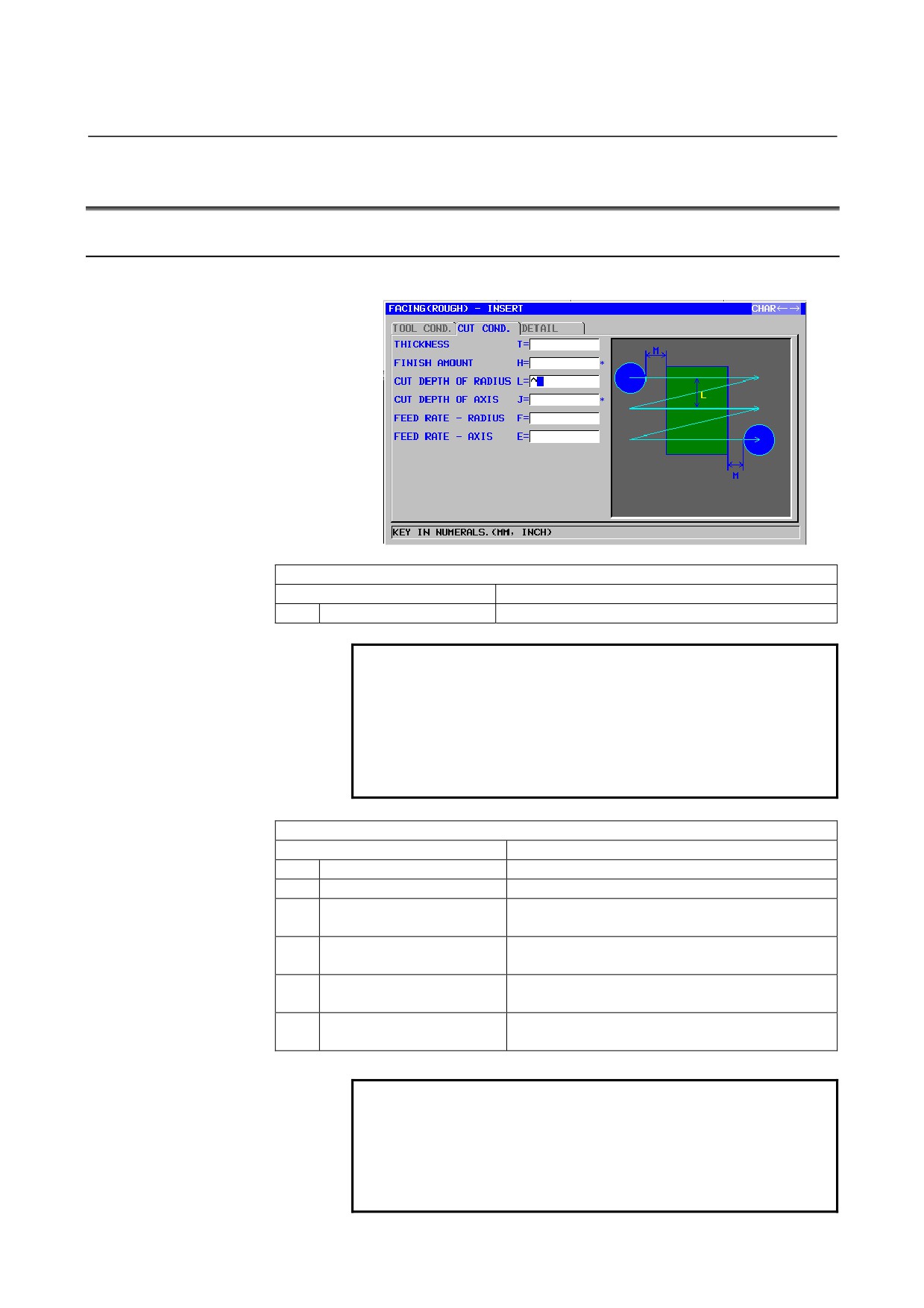
Rough: G1020
TOOL COND.
Data item
Meaning
D
TOOL DIAMETER
Face mill diameter
NOTE
1 Tab ‘TOOL COND.’ is enabled when bit 0 (TLG) of
parameter No. 27002 = 1.
2 The operator ordinarily sets the above data on the
tab of ‘TOOL DATA’ in Tool Offset window.
Therefore, it is not necessary to display the tab
‘TOOL COND.’
CUT COND.
Data item
Meaning
T*
THICKNESS
Face mill diameter
H*
FINISH AMOUNT
Finishing allowance in facing
L
CUT DEPTH OF RADIUS
Depth of cut in the tool radius direction to the next
cutting path
J
CUT DEPTH OF AXIS
Depth of cut in the tool axis direction per cutting
operation
F
FEED RATE - RADIUS
Feedrate applicable when cutting is performed in
the tool radius direction
E
FEED RATE - AXIS
Feedrate applicable when cutting is performed in
the tool axis direction
NOTE
If the parameter 27030#1=1, only the menu of
perpendicular directions to “CUTTING
DIRECTION” can have been displayed during in
case of selecting “CUT SHIFT DIRECTION”. Thus,
the extra selection can be removed.
- 370 -
B-63874EN/05
CYCLE MACHINING TYPES
1.MILLING
DETAIL
Data item
Meaning
I
INITIAL FEED OVERRIDE
Feedrate override value for the first cutting. The
initial value is 100 (1 to 200, positive value).
W
CUTTING METHOD
[SINGLE] : Cutting in the tool radius direction is
always performed in the same
direction.
[ZIGZAG] : Cutting in the tool radius direction is
performed back and forth.
(COPY)
P
PATH MOVE METHOD
[PULL]
: Retracts to point R before moving to the
start point of the next cutting path (in
the tool axis direction).
[KEEP]
: Moves to the start point of the next
cutting path directly without retracting to
point R.
Remark1) This data item is indicated only when
[ZIGZAG] is selected for CUTTING
METHOD.
Remark2) This data item is enabled when the
parameter No.27030#0(FC0) = 0.
Remark3) In case that the movement is done
by 1 axis, tool is kept even if [PULL]
is specified.
Remark4) If [KEEP] is specified, an end point
of previous cutting motion is
adjusted in order to enable a tool to
move with 1 axis to next cutting
start point
(COPY)
V
PATH MOVE FEED RATE
Feedrate applicable when the tool moves to the
start point of the next cutting path. In case that
the feedrate is set to 0, the tool moves at a
rapid traverse rate.
Remark1) This data item is indicated only when
[ZIGZAG] is selected for CUTTING
METHOD.
Remark2) This data item is enabled when the
parameter No.27030#0(FC0) = 0.
(COPY)
C
CLEARANCE OF AXIS
Distance between the surface of a blank being
machined and a cutting start point (point R) in the
tool axis direction (radius value)
Remark) By referring to the parameter No.27009
(minimum clamp value), the system sets
the data as Initial value.
M
CLERANCE OF RADIUS
Distance between the end of a blank being
machined and the end of the tool placed at the
retract position (radius value)
Remark) By referring to the parameter No.27009
(minimum clamp value), the system sets
the data as Initial value.
- 371 -