FANUC Series 16i/160i/160is-MODEL B, Series 18i/180i/180is-MODEL B, Series 21i/210i/210is-MODEL B. MAINTENANCE MANAUL - page 29
11. TROUBLESHOOTING
B-63525EN/02
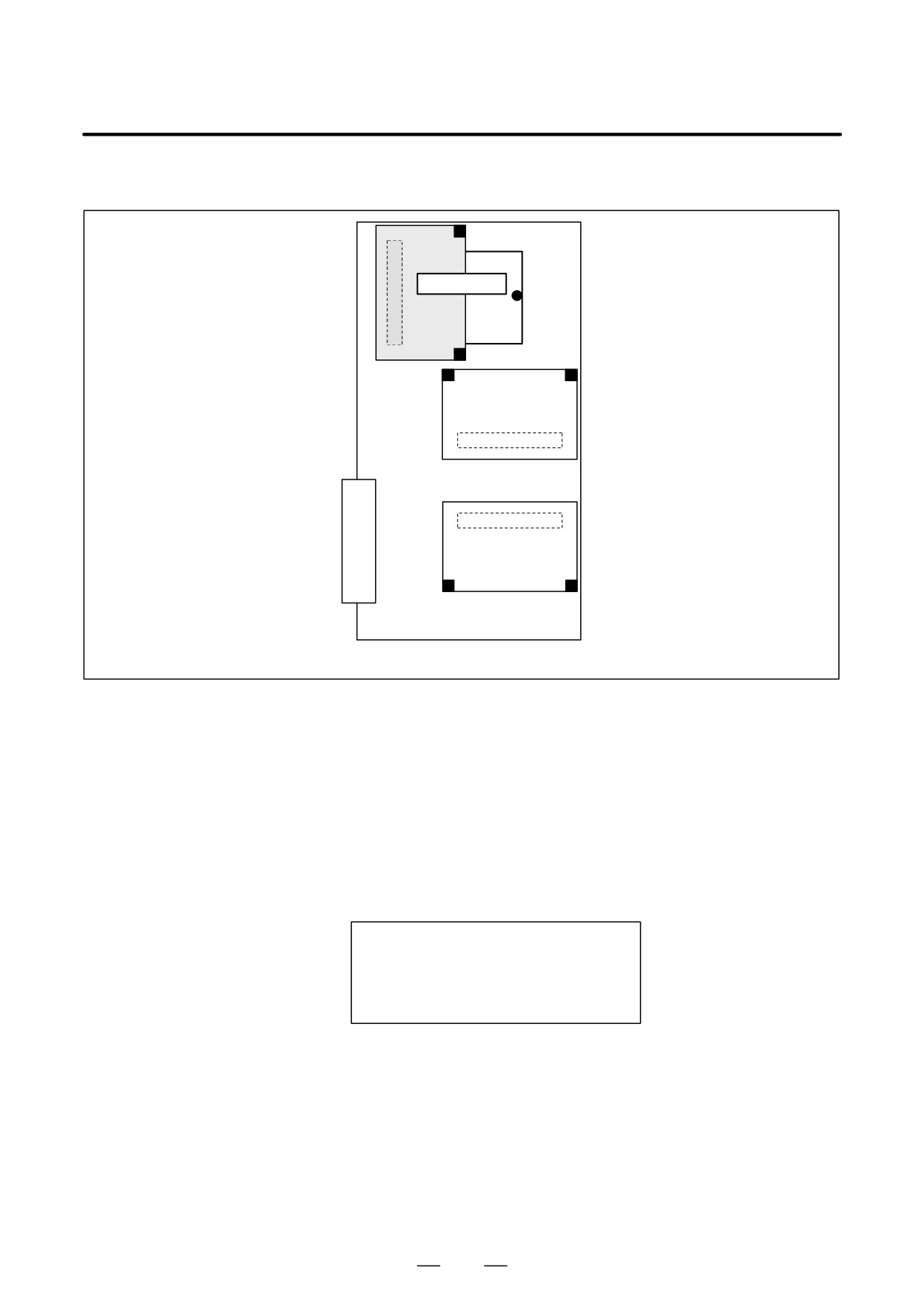
[For the stand-alone type]
CPU card
Main CPU board
D Examining the noise
See the section on the measures against noise, examine the noise
environment
environment of the CNC.
D CPU interrupt on an
If alarm 972 is issued, indicating on the screen that a CPU interrupt was
option board
generated on an option board, take appropriate action on the option board
on which the CPU interrupt was generated.
Some option boards have a circuit equivalent to the CPU card installed
on the boards themselves. See the hardware chapter for details.
Screen display example
SYSTEM ALARM
972 NMI OCCURRED IN OTHER MODULE
SLOT 01
930 CPU INTERRUPT <SUB
812
B-63525EN/02
11.TROUBLESHOOTING
11.32
ALARM 935
(SRAM ECC ERROR)
Causes and actions
An ECC error occurred in the SRAM used to store data such as parameters
and machining programs.
This alarm is issued if the battery has run down or if the data in the SRAM
is destroyed due to some external cause. Or, the FROM/SRAM module
or motherboard may be defective.
D ECC check
This is the method of checking the data stored in the SRAM. It has been
employed instead of the conventional parity check.
With the ECC check method, 8-bit correction data is provided for 16-bit
data, so that if a data error occurs in one of these 16 bits, the error is
automatically corrected with the correction data, allowing the CNC to
continue operation. This alarm is issued if a data error occurs in two or
more bits.
With the conventional parity check method, a system alarm is issued if a
data error occurs even in one bit.
D Checking the battery
The battery is rated 3 V. A battery alarm is issued and “BAT” flashes on
the screen if the voltage of the battery drops to 2.6 V.
If a battery alarm is issued, replace the battery with a new one promptly.
D Performing memory all
Perform a memory all clear operation, then start up the CNC.
clear
Alternatively, if a backup of the data in the SRAM has been made, use the
backup to restore the data. To back up and restore the data in the SRAM,
use the boot system.
D Replacing the
If memory all clear or the restoration of the data with a backup does not
FROM/SRAM module
solve the problem, replace the FROM/SRAM module. Take a backup
copy in advance. All the software must be restored after the replacement.
After replacing the FROM/SRAM module, perform a memory all clear
operation and start up the CNC. All the data must be re-loaded.
If a backup is available, restore the data using the backup, then start up
the CNC.
D Motherboard
If any of the above actions does not solve the problem, replace the
motherboard.
813
11. TROUBLESHOOTING
B-63525EN/02
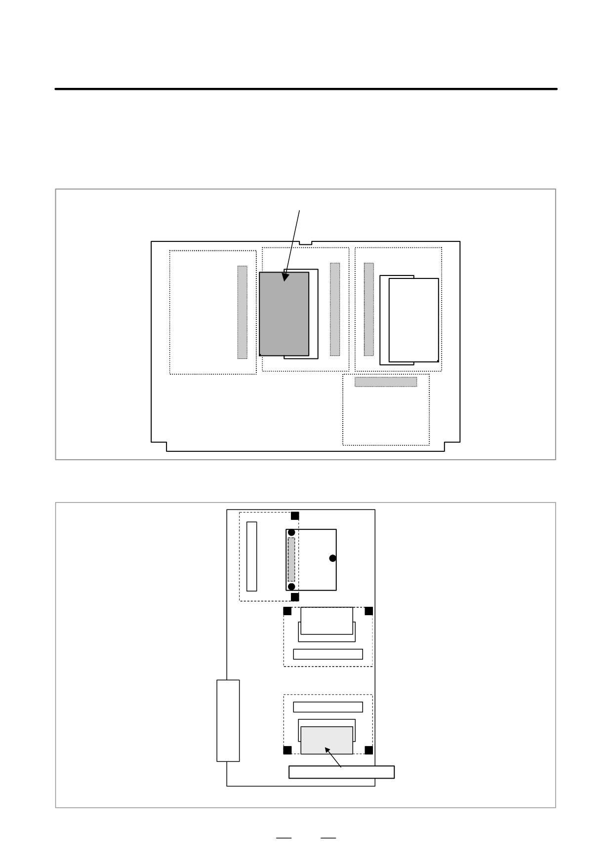
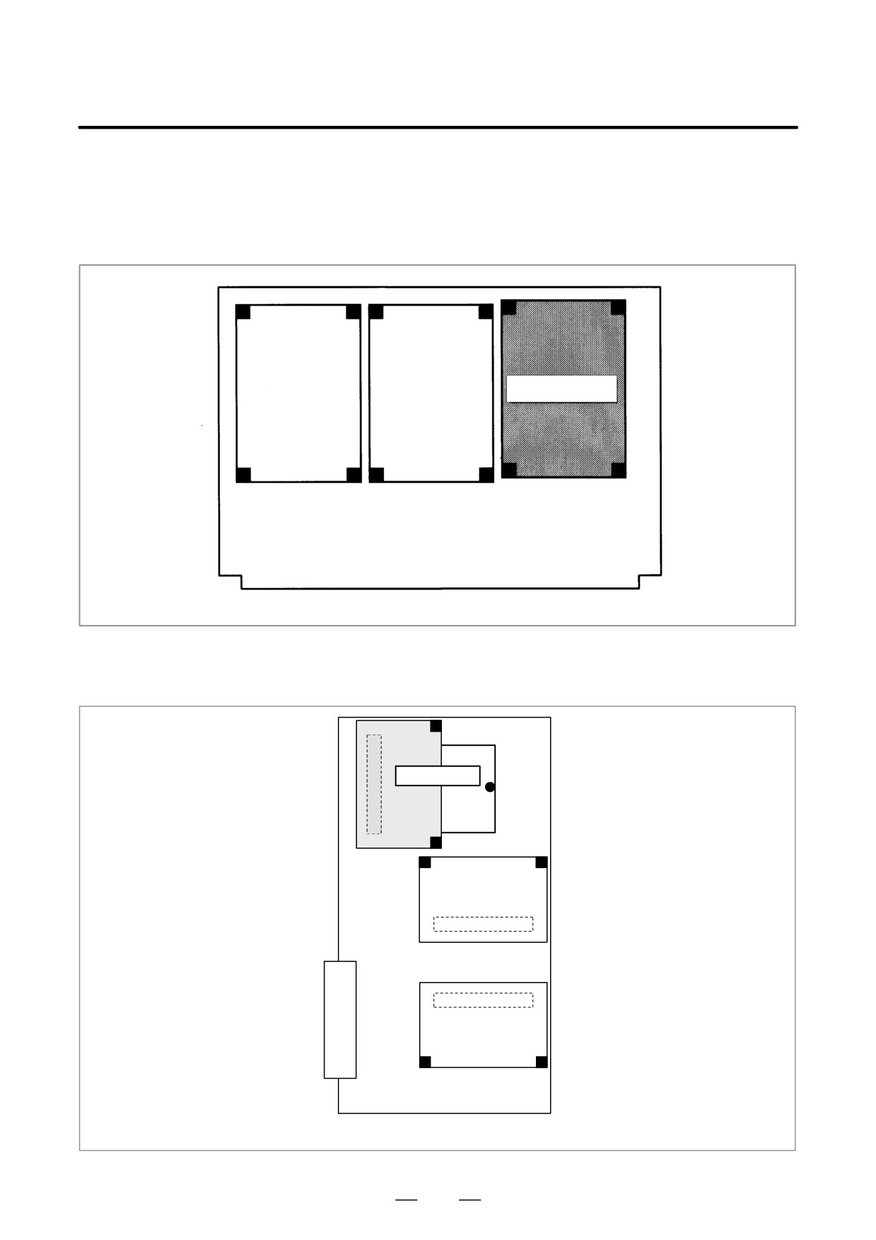
D Installation position of
the FROM/SRAM module
[For the LCD-mounted type]
FROM/SRAM module
[For the stand-alone type]
The FROM/SRAM module
FROM/SRAM module
is installed under the axis
control card.
Main CPU board
814
B-63525EN/02
11.TROUBLESHOOTING
11.33
ALARM 950
(PMC SYSTEM
ALARM)
Causes and actions
This alarm is issued if a fault is detected in the PMC.
The probable causes include an I/O link communication error and a
defective PMC control circuit
D Connecting the I/O Link
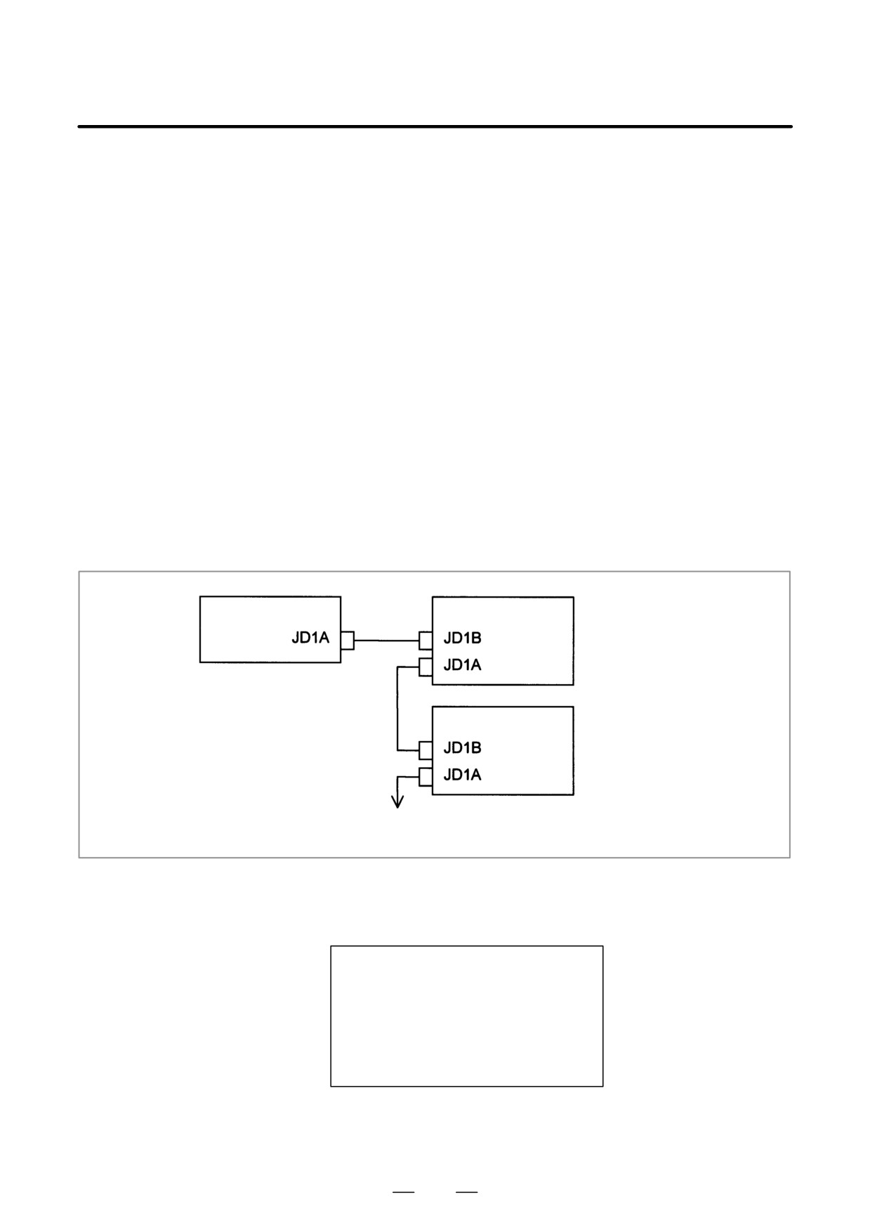
The I/O Link is a serial interface that connects the CNC to various I/O
devices and allows transfers of I/O signals between devices at high speed.
When multiple devices are connected using the I/O Link, there forms a
relationship that a certain device is a master and the other devices are
slaves. The states of the input signals from the slaves are transferred to
the master at fixed intervals. The output signals from the master are
transferred to the slaves at fixed intervals. In a CNC system, the master
is the CNC (motherboard or main CPU board).
The I/O signals transferred via the I/O link can be used with the PMC
Ladder.
Master station (CNC)
Slave station #0
Group 0
Slave station #1
Group 1
Up to 16 groups
D I/O Link communication
If alarm 950 is issued, displaying “PC050” on the screen, an I/O link
error PC050
communication error may have occurred.
Screen display example
SYSTEM ALARM
950 PMC SYSTEM ALARM
PC050 I/OLINK(CH1)
xx:yy-aa:bb
or
PC050 I/OLINK(CH2)
aa:bb-xx:yy
or
PC050 IOLINK CH1
aabb-xxyy:aabb
or
PC050 IOLINK CH2
aabb:aabb-xxyy
In this screen display example, the cause of the alarm can be estimated
using xx:yy. xx and yy are hexadecimal representations. CH1 and CH2
are channels on which communication failed.
815
11. TROUBLESHOOTING
B-63525EN/02
1)
If bit 0 of the binary representation of xx is “1”, this indicates that the
master station (CNC) received invalid communication data. For
example, assume that the following is displayed on the screen:
SYSTEM ALARM
950 PMC SYSTEM ALARM
PC050 IOLINK CH1
aabb-4142:aabb
xx is equal to 41, or “01000001” in binary notation. Bit 0, which is
the lowest (rightmost) bit, is “1”.
In this case, check the following:
(1) Noise environment of the I/O Link cable
Noise may disturb the data on the I/O Link and may result in a
problem.
(2) Contact of the I/O Link cable
Check that the I/O link cable is in contact. Check that the cable is
not loose and is latched firmly.
(3) Cable failure
Check that the I/O Link cable is connected properly.
(4) Device failure
The motherboard or any of the I/O devices connected to the I/O
Link may be defective. Replace the devices, one at a time, to
identify the defective device.
Refer to 2) if bit 1 (second bit from the right) is also “1”.
2)
If bit 1 of the binary representation of xx is “1”, this indicates that an
error was detected on a slave station (I/O device). For example,
assume that the following is displayed on the screen:
SYSTEM ALARM
950 PMC SYSTEM ALARM
PC050 IOLINK CH1
aabb-4382:aabb
xx is equal to 43, or “01000011” in binary notation. Bit 1 (second bit
from the right) is “1”.
In this case, yy indicates the following:
Number equal to the number indicated by bits 0 to 4 of yy minus 1:
Group number of the slave station on which an error was detected
Bit 5 of yy:
Invalid communication data was detected on the slave.
Bit 6 of yy:
Another error was detected on the slave.
Bit 7 of yy:
A watchdog or parity error was detected on the slave.
In the example shown in the figure above, yy is equal to 82, or
“10000010” in binary notation. Bits 0 to 4 are “00010” (2 in decimal
notation). The number “1”, which is equal to that number minus 1, is
the group number of the slave station on which an error was detected.
Bit 7 is “1”. Thus, a watchdog or parity error was detected on the slave
station in group 1.
816
B-63525EN/02
11.TROUBLESHOOTING
In this case, check the following:
(1) If bit 5 of yy is “1”
Perform examination with the same procedure as that in 1).
(2) If bit 6 of yy is “1” or if bit 7 of yy is “1”
First, replace the device of the slave station of the indicated group
number.
If the problem is not solved, perform examination with the same
procedure as that in 1) to identify the defective location.
3)
If bit 2 of the binary representation of xx is “1”, this indicates that the
link between the master station (CNC) and the slave station was
canceled. For example, assume that the following is displayed on the
screen:
SYSTEM ALARM
950 PMC SYSTEM ALARM
PC050 IOLINK CH1
aabb-8400:aabb
xx is equal to 84, or “1000100” in binary notation. Bit 2, which is the
third bit from the right, is “1”.
In this case, check the following:
(1) Disconnection of the slave station from the power supply
Check that the slave station is not turned off, that there are no
instantaneous power failures, and that the capacity of the power
supply is enough.
(2) Disconnection of the I/O link cable
Check that the I/O link cable has not fallen off or has not been
disconnected.
(3) If the problem is not solved, perform a check with the same
procedure as that in 1).
4)
If bit 3 or 4 of the binary representation of xx is “1”, this indicates that
a parity error occurred in the PMC control circuit on the motherboard.
In this case, replace the motherboard (main CPU board).
D Other cases
The motherboard may be defective. Replace the motherboard.
D PMC system alarm on
For sequence control on the loader control board, a PMC control circuit
the loader control board
is installed on the loader control board.
If alarm 972 is issued, indicating on the screen that a PMC system alarm
occurred on the loader, take appropriate action on the loader control
board.
Screen display example
SYSTEM ALARM
972 NMI OCCURRED IN OTHER MODULE
SLOT 01
950 PMC SYSTEM ALARM >LC
817
11. TROUBLESHOOTING
B-63525EN/02
11.34
ALARM 951
(PMC WATCHDOG
ALARM)
Causes and actions
This alarm is issued if a fault (watchdog alarm) is detected in the PMC.
A probable cause is that the MC control circuit is defective.
D Replacing the
The PMC control circuit is installed on the motherboard. Replace the
motherboard
motherboard.
D PMC watchdog alarm on
For sequence control on the loader control board, a PMC control circuit
the loader control board
is installed on the loader control board.
If alarm 972 is issued, indicating on the screen that a PMC watchdog
alarm occurred on the loader, take appropriate action on the loader control
board.
Screen display example
SYSTEM ALARM
972 NMI OCCURRED IN OTHER MODULE
SLOT 01
951 PMC WATCH DOG ALARM >LC
818
B-63525EN/02
11.TROUBLESHOOTING
11.35
ALARM 972
(NMI ALARM ON AN
OPTION BOARD)
Causes and actions
This alarm indicates that an error was detected on an option board, not on
the main CPU board.
D Screen display
If alarm 972 is issued, the following is displayed on the screen:
Screen display example
SYSTEM ALARM
972 NMI OCCURRED IN OTHER MODULE
SLOT 02
930 CPU INTERRUPT <SUB
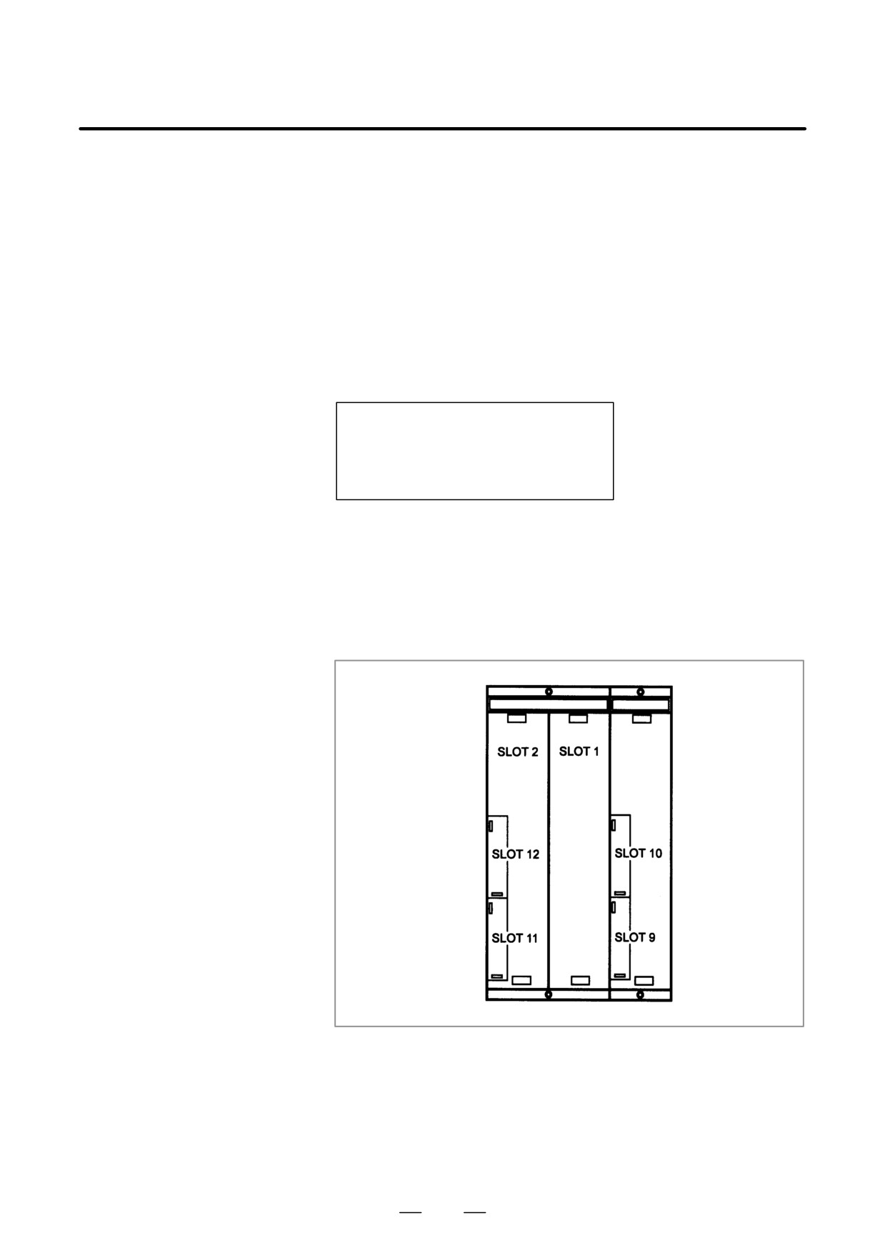
“SLOT” indicates the number of the slot into which the option board is
inserted. Alternatively, it may indicate the number of the alarm that
occurred on the option board. Take the action related to that alarm to the
option board. In the above example, alarm 930 occurred on the sub-CPU
board.
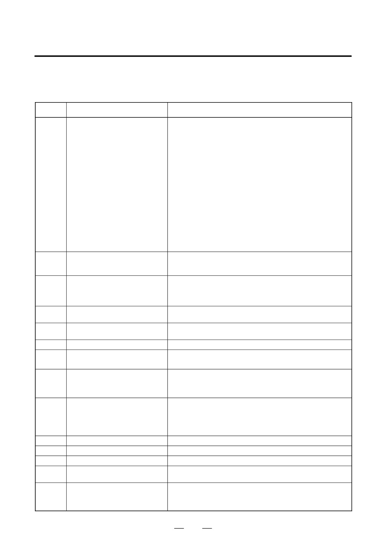
D Slot number
The slot number of each option slot is as shown in the figure below.
D Replacing the option
Replace the option board inserted into the slot with the indicated slot
board
number.
819
11. TROUBLESHOOTING
B-63525EN/02
11.36
ALARM 973
(NMI ALARM WITH
AN UNKNOWN
CAUSE)
Causes and actions
An error that can never occur during normal operation occurred. The
cause of the error cannot be identified.
D Replacing printed circuit
Replace all the printed circuit boards installed (including cards, modules,
boards
and the back panel), one at a time, to identify the defective printed circuit
board.
Replace the CPU card, motherboard, and other printed circuit boards, one
at a time.
820
B-63525EN/02
11.TROUBLESHOOTING
11.37
ALARM 974
(F-BUS ERROR)
Causes and actions
A bus error occurred on the FANUC-BUS connecting each option board.
This alarm indicates that a fault occurred during the exchange of data
between the main CPU and an option board.
D Replacing the CPU card
Replace the CPU card on the motherboard.
D Replacing the
Replace the motherboard.
motherboard
D Replacing the option
Replace the installed option boards, one at a time.
boards
D Replacing the back panel
Replace the back panel.
821
11. TROUBLESHOOTING
B-63525EN/02
D Installation position of
the CPU card
[For the LCD-mounted type]
CPU card
Motherboard
[For the stand-alone type]
CPU card
Main CPU board
822
B-63525EN/02
11.TROUBLESHOOTING
D F-BUS error on an
If alarm 972 is issued, indicating on the screen that an F-BUS error
option board
occurred on an option board, replace the CPU card on the option board
on which the F-BUS error occurred or the option board itself.
Some option boards have a circuit equivalent to the CPU card installed
on the boards themselves. See the hardware chapter for details.
In this case, the back panel or motherboard may be defective. Take the
actions described on the previous page.
Screen display example
SYSTEM ALARM
972 NMI OCCURRED IN OTHER MODULE
SLOT 01
974 FĆBUS ERROR <SUB
823
11. TROUBLESHOOTING
B-63525EN/02
11.38
ALARM 975
(BUS ERROR)
Causes and actions
A bus error occurred on the motherboard. This alarm indicates that an
error occurred during the exchange of data within the motherboard.
D Replacing the CPU card
Replace the CPU card on the motherboard.
D Replacing other cards
Replace the display control card, axis control cards, and FROM/SRAM
and modules
module, one at time.
D Replacing the
Replace the motherboard.
motherboard
D BUS error on an option
If alarm 972 is issued, indicating on the screen that a BUS error occurred
board
on an option board, replace the CPU card on the option card, DRAM
module, axis control cards, and option card, one at a time.
Some option boards have a circuit equivalent to the CPU card installed
on the boards themselves. See the hardware chapter for details.
Screen display example
SYSTEM ALARM
972 NMI OCCURRED IN OTHER MODULE
SLOT 01
975 FĆBUS ERROR <SUB
824
B-63525EN/02
11.TROUBLESHOOTING
11.39
ALARM 976
(LOCAL BUS ERROR)
Causes and actions
A bus error occurred on the local bus on the motherboard.
This alarm indicates that an error occurred during the exchange of data
within the motherboard.
D Replacing the CPU card
Replace the CPU card on the motherboard (main CPU board).
D Replacing other cards
Replace the display control card, axis control cards, and FROM/SRAM
and modules
module, one at a time.
D Replacing the
Replace the motherboard.
motherboard
D Local BUS error on an
If alarm 972 is issued, indicating on the screen that a local BUS error
option board
occurred on an option board, replace the CPU card on the option card,
DRAM module, axis control cards, and option card, one at a time.
Some option boards have a circuit equivalent to the CPU card installed
on the boards themselves. See the hardware chapter for details.
Screen display example
SYSTEM ALARM
972 NMI OCCURRED IN OTHER MODULE
SLOT 01
976 LĆBUS ERROR <SUB
825
11. TROUBLESHOOTING
B-63525EN/02
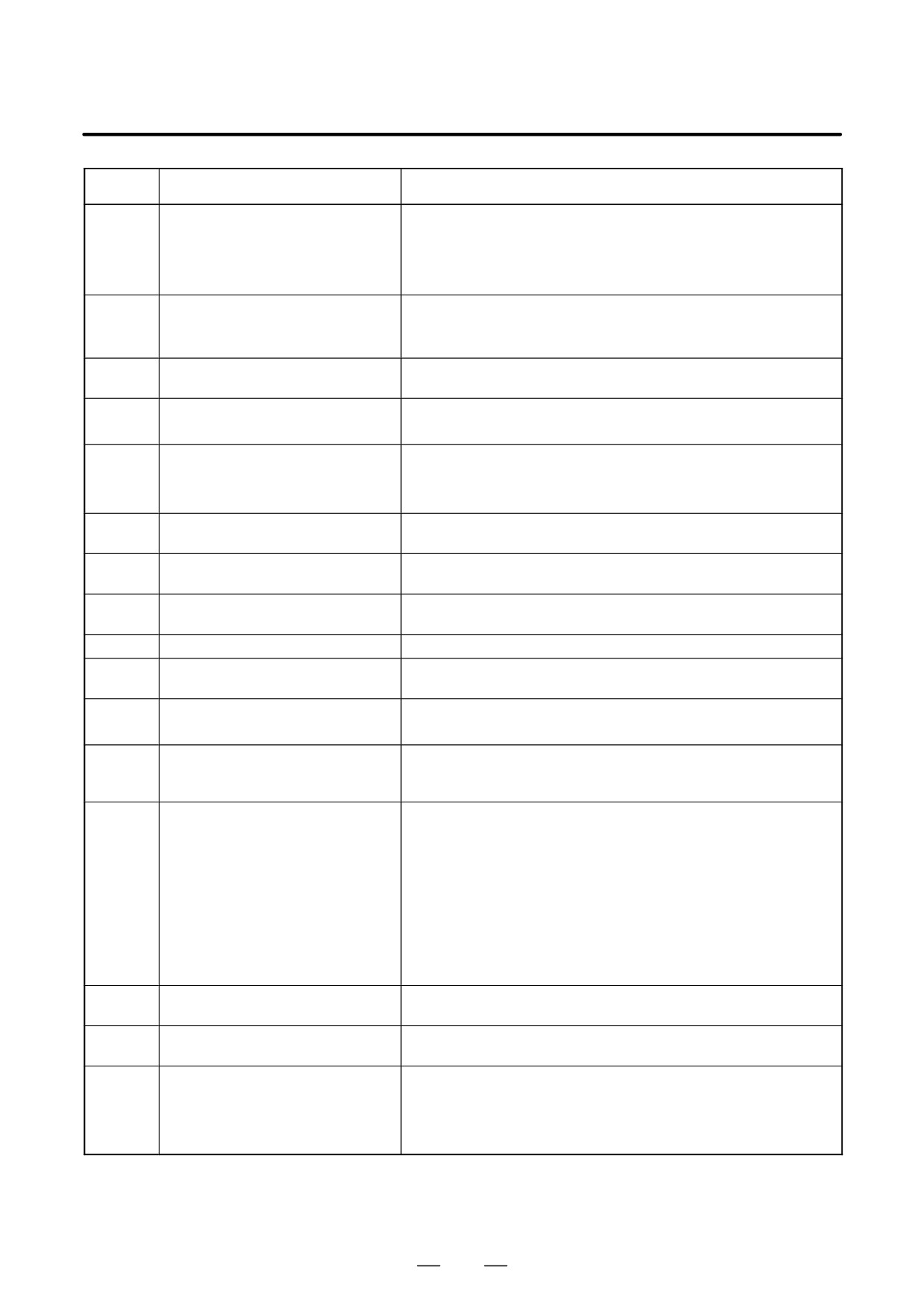
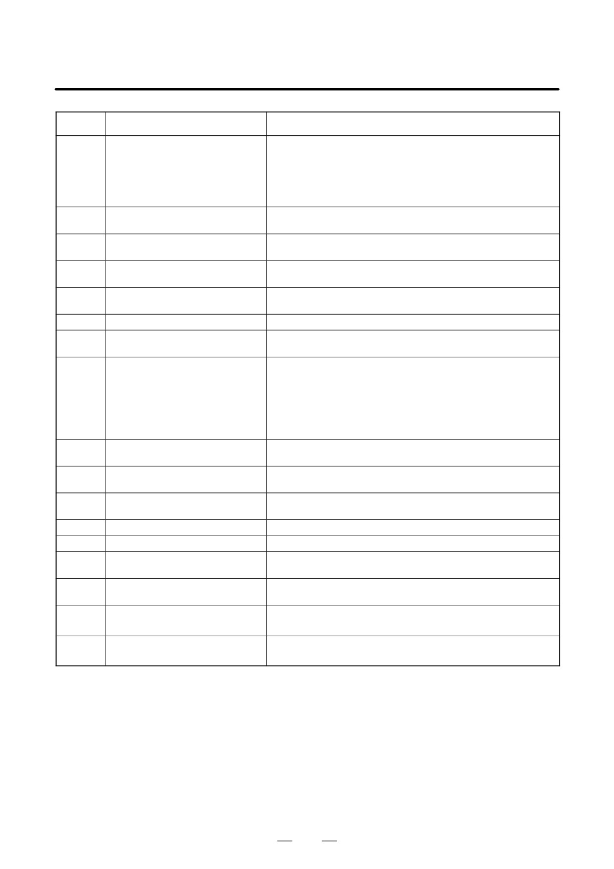
For an explanation of the following servo alarms, refer to the FANUC
11.40
SERVO MOTOR αi series Maintenance Manual (B-65285EN) or
SERVO ALARMS
FANUC SERVO MOTOR α series Maintenance Manual (B-65165E).
Number
Message
Contents
417
SERVO ALARM: n-TH AXIS - PA-
This alarm occurs when the n-th axis (axis 1-8) is in one of the condi-
RAMETER INCORRECT
tions listed below. (Digital servo system alarm)
1) The value set in Parameter No. 2020 (motor form) is out of the speci-
fied limit.
2) A proper value (111 or -111) is not set in parameter No.2022 (motor
revolution direction).
3) Illegal data (a value below 0, etc.) was set in parameter No. 2023
(number of speed feedback pulses per motor revolution).
4) Illegal data (a value below 0, etc.) was set in parameter No. 2024
(number of position feedback pulses per motor revolution).
5) Parameters No. 2084 and No. 2085 (flexible field gear rate) have not
been set.
6) A value outside the limit of {1 to the number of control axes} or a non-
continuous value (Parameter 1023 (servo axis number) contains a
value out of the range from 1 to the number of axes, or an isolated
value (for example, 4 not prceded by 3).was set in parameter No.
1023 (servo axisnumber).
420
SERVO ALARM: n AXIS SYNC
During simple synchronous control, the difference between the torque
TORQUE
commands for the master and slave axes exceeded the value set in pa-
rameter No. 2031.
421
SERVO ALARM: n AXIS EXCESS
The difference between the errors in the semi-closed loop and closed
ER (D)
loop has become excessive during dual position feedback. Check the
values of the dual position conversion coefficients in parameters No.
2078 and 2079.
422
SERVO ALARM: n AXIS
In torque control of PMC axis control, a specified allowable speed
has been exceeded.
423
SERVO ALARM: n AXIS
In torque control of PMC axis control, the parameter-set allowable
cumulative travel distance has been exceeded.
430
n AXIS : SV. MOTOR OVERHEAT
A servo motor overheat occurred.
431
n AXIS : CNV. OVERLOAD
1) PSM: Overheat occurred.
2) β series SVU: Overheat occurred.
432
n AXIS : CNV. LOWVOLT CON.
1) PSM: The control power supply voltage has dropped.
2) PSMR: The control power supply voltage has dropped.
3) β series SVU: The control power supply voltage has dropped.
433
n AXIS : CNV. LOWVOLT DC LINK
1) PSM: The DC link voltage has dropped.
2) PSMR: The DC link voltage has dropped.
3) α series SVU: The DC link voltage has dropped.
4) β series SVU: The DC link voltage has dropped.
434
n AXIS : INV. LOWVOLT CONTROL
SVM: The control power supply voltage has dropped.
435
n AXIS : INV. LOWVOLT DC LINK
SVM: The DC link voltage has dropped.
436
n AXIS : SOFTTHERMAL (OVC)
The digital servo software detected the soft thermal state (OVC).
437
n AXIS : CNV. OVERCURRENT
PSM: Overcurrent flowed into the input circuit.
POWER
438
n AXIS : INV. ABNORMAL CUR-
1) SVM: The motor current is too high.
RENT
2) α series SVU: The motor current is too high.
3) β series SVU: The motor current is too high.
826
B-63525EN/02
11.TROUBLESHOOTING
Number
Message
Contents
439
n AXIS : CNV. OVERVOLT POWER
1) PSM: The DC link voltage is too high.
2) PSMR: The DC link voltage is too high.
3) α series SVU: The C link voltage is too high.
4) β series SVU: The link voltage is too high.
440
n AXIS : CNV. EX DECELERATION
1) PSMR: The regenerative discharge amount is too large.
POW.
2) α series SVU: The regenerative discharge amount is too large. Al-
ternatively, the regenerative discharge circuit is abnormal.
441
n AXIS : ABNORMAL CURRENT
The digital servo software detected an abnormality in the motor cur-
OFFSET
rent detection circuit.
442
n AXIS : CNV. CHARGE FAULT
1) PSM: The spare discharge circuit of the DC link is abnormal.
2) PSMR: The spare discharge circuit of the DC link is abnormal.
443
n AXIS : CNV. COOLING FAN FAIL-
1) PSM: The internal stirring fan failed.
URE
2) PSMR: The internal stirring fan failed.
3) β series SVU: The internal stirring fan failed.
444
n AXIS : INV. COOLING FAN FAIL-
SVM: The internal stirring fan failed.
URE
445
n AXIS : SOFT DISCONNECT
The digital servo software detected a broken wire in the pulse coder.
ALARM
446
n AXIS : HARD DISCONNECT
A broken wire in the built-in pulse coder was detected by hardware.
ALARM
447
n AXIS : HARD DISCONNECT (EXT)
A broken wire in the separate detector was detected by hardware.
448
n AXIS : UNMATCHED FEEDBACK
The sign of feedback data from the built-in pulse coder differs from
ALARM
that of feedback data from the separate detector.
449
n AXIS : INV. IPM ALARM
1) SVM: IPM (intelligent power module) detected an alarm.
2) α series SVU: IPM (intelligent power module) detected an alarm.
453
n AXIS : SPC SOFT DISCONNECT
Software disconnection alarm of the α pulse coder.
ALARM
Turn off the power to the CNC, then remove and insert the pulse cod-
er cable. If this alarm is issued again, replace the pulse coder.
456
ILLEGAL CURRENT LOOP
The current control cycle settings (parameter No. 2004, bit 0 of pa-
rameter No. 2003, and bit 0 of parameter No. 2013) are incorrect.
Possible problems are as follows.
- For the two axes whose servo axis numbers (settings of parameter
No. 1023) are an odd number followed by an even number (a pair
of axes 1 and 2 or axes 5 and 6, for example), a different current con-
trol cycle is set for each of the axes.
- The requirements for slaves needed for the set current control cycle,
including the number, type, and connection method of them, are not
satisfied.
457
ILLEGAL HI HRV (250US)
Use of high-speed HRV is specified although the current control
cycle is 200 ms.
458
CURRENT LOOP ERROR
The current control cycle setting does not match the actual current
control cycle.
459
HI HRV SETTING ERROR
For the two axes whose servo axis numbers (settings of parameter
No. 1023) are an odd number followed by an even number (a pair of
axes 1 and 2 or axes 5 and 6, for example), the SVM for one of the
axes supports high-speed HRV control but the SVM for the other
does not. Refer to the SVM specification.
827
11. TROUBLESHOOTING
B-63525EN/02
Number
Message
Contents
460
n AXIS : FSSB DISCONNECT
FSSB communication was disconnected suddenly. The possible
causes are as follows:
1) The FSSB communication cable was disconnected or broken.
2) The power to the amplifier was turned off suddenly.
3) A low-voltage alarm was issued by the amplifier.
461
n AXIS : ILLEGAL AMP INTERFACE
The axes of the 2-axis amplifier were assigned to the fast type inter-
face.
462
n AXIS : SEND CNC DATA FAILED
Because of an FSSB communication error, a slave could not receive
correct data.
463
n AXIS : SEND SLAVE DATA
Because of an FSSB communication error, the servo system could
FAILED
not receive correct data.
464
n AXIS : WRITE ID DATA FAILED
An attempt was made to write maintenance information on the ampli-
fier maintenance screen, but it failed.
465
n AXIS : READ ID DATA FAILED
At power-up, amplifier initial ID information could not be read.
466
n AXIS : MOTOR/AMP COMBINA-
The maximum current rating for the amplifier does not match that for
TION
the motor.
467
n AXIS : ILLEGAL SETTING OF
The servo function for the following has not been enabled when an
AXIS
axis occupying a single DSP (corresponding to two ordinary axes) is
specified on the axis setting screen.
1. Learning control (bit 5 of parameter No. 2008 = 1)
2. High-speed current loop (bit 0 of parameter No. 2004 = 1)
3. High-speed interface axis (bit 4 of parameter No. 2005 = 1)
468
HI HRV SETTING ERROR (AMP)
Use of high-speed HRV is specified for a controlled axis of an ampli-
fier which does not support high-speed HRV.
600
n AXIS : INV. DC LINK OVER CUR-
DC link current is too large.
RENT
601
n AXIS : INV. RADIATOR FAN FAIL-
The external dissipator stirring fan failed.
URE
602
n AXIS : INV. OVERHEAT
The servo amplifier was overheated.
603
n AXIS : INV. IPM ALARM (OH)
The IPM (intelligent power module) detected an overheat alarm.
604
n AXIS : AMP. COMMUNICATION
Communication between the SVM and the PSM failed.
ERROR
605
n AXIS : CNV. EX. DISCHARGE
PSMR: Regenerative power is too large.
POW.
606
n AXIS : CNV. RADIATOR FAN FAIL-
PSM: The external dissipator stirring fan failed.
URE
PSMR: The external dissipator stirring fan failed.
607
n AXIS : CNV. SINGLE PHASE FAIL-
PSM: Input voltage is in the open-phase condition.
URE
PSMR: Input voltage is in the open-phase condition.
If the hardware on the CNC is suspected to be defective as a result of
examination, replace the axis control cards.
828
B-63525EN/02
11.TROUBLESHOOTING
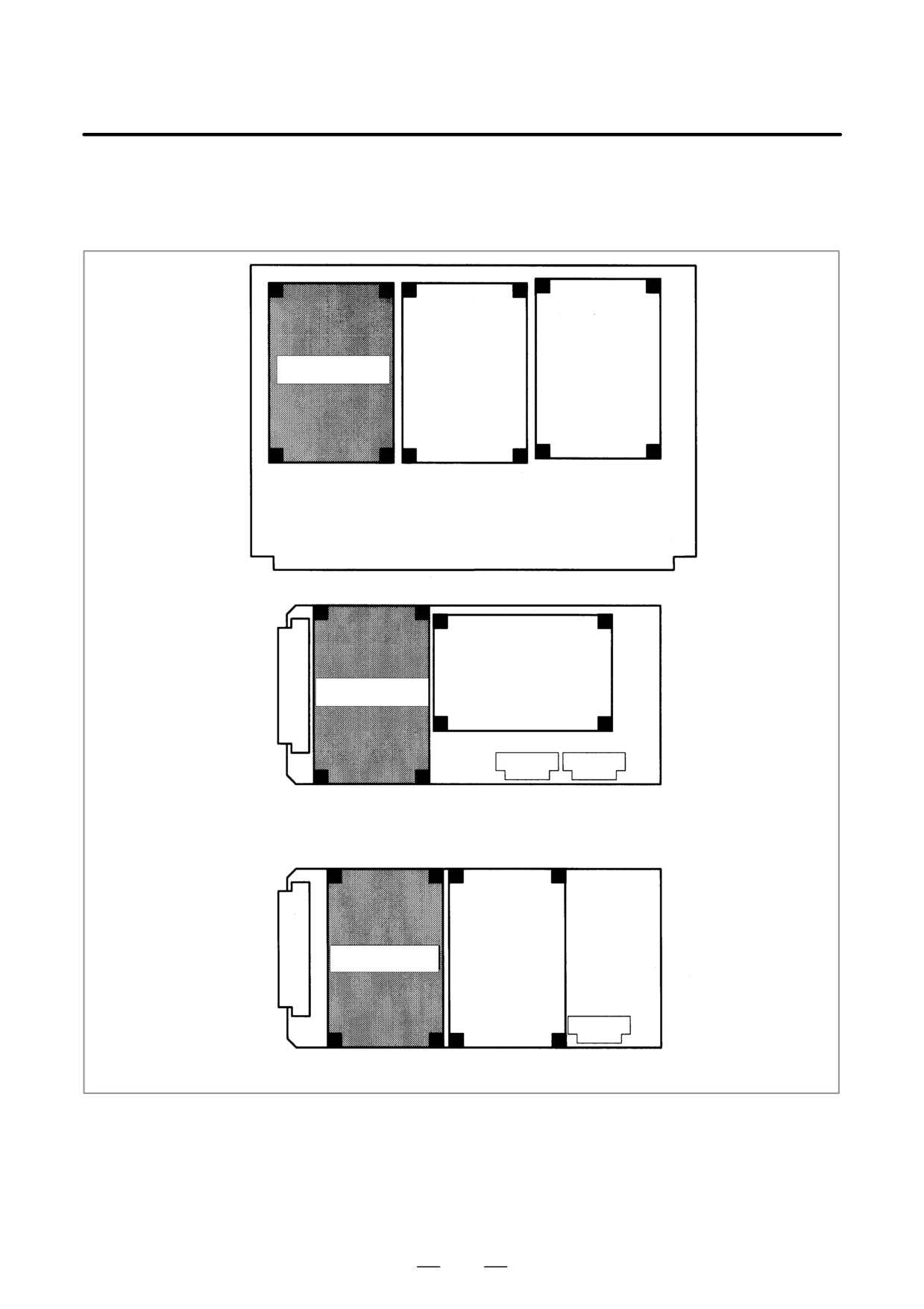
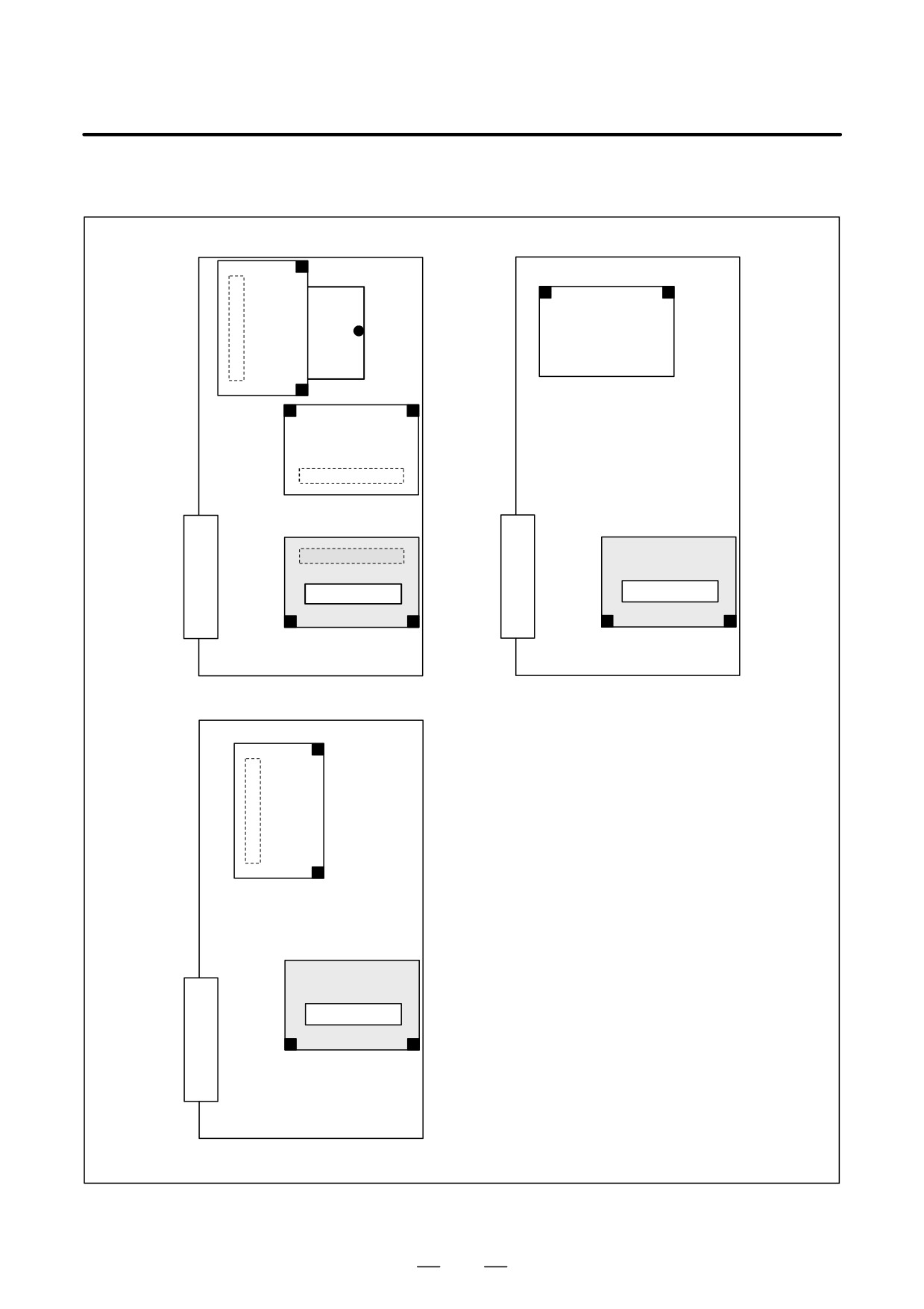
D Installation positions of
the axis control cards
[For the LCD-mounted type]
Axis control card
Motherboard
Axis control card
Sub-CPU board
Axis control card
Loader control card
829
11. TROUBLESHOOTING
B-63525EN/02
[For the stand-alone type]
Axis control card
Axis control card
Main CPU board
Sub CPU board
Axis control card
Loarder control board
830
B-63525EN/02
11.TROUBLESHOOTING
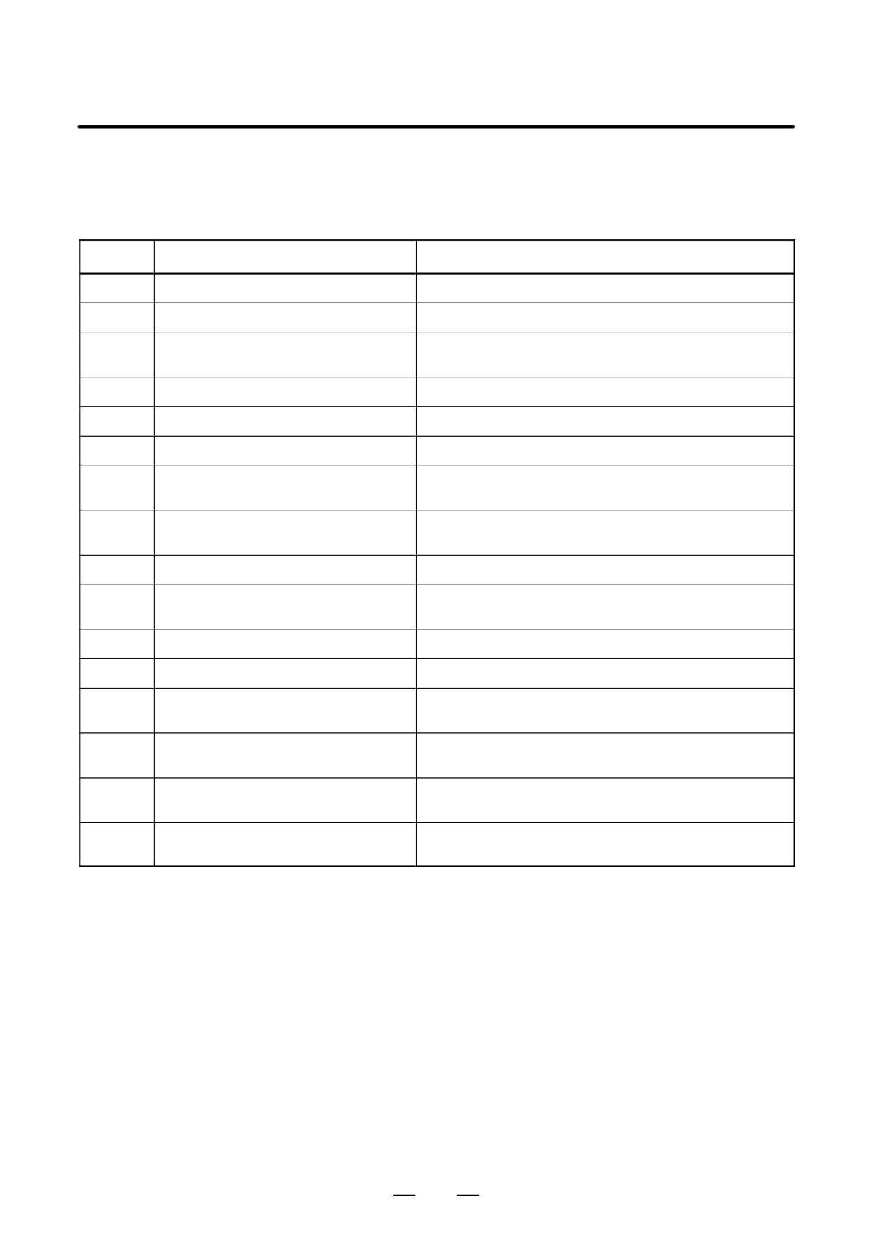
For an explanation of the following SPC alarms (serial pulse coder
11.41
alarms), refer to the FANUC SERVO MOTOR αi series Maintenance
SPC ALARMS
Manual
(B-65285EN) or FANUC SERVO MOTOR α series
Maintenance Manual (B-65165E).
Number
Message
Contents
360
n AXIS: ABNORMAL CHECKSUM (INT)
A checksum error occurred in the built-in pulse coder.
361
n AXIS: ABNORMAL PHASE DATA (INT)
A phase data error occurred in the built-in pulse coder.
364
n AXIS: SOFT PHASE ALARM (INT)
The digital servo software detected invalid data in the built-in
pulse coder.
365
n AXIS: BROKEN LED (INT)
An LED error occurred in the built-in pulse coder.
366
n AXIS: PULSE MISS (INT)
A pulse error occurred in the built-in pulse coder.
367
n AXIS: COUNT MISS (INT)
A count error occurred in the built-in pulse coder.
368
n AXIS: SERIAL DATA ERROR (INT)
Communication data from the built-in pulse coder cannot be
received.
369
n AXIS: DATA TRANS. ERROR (INT)
A CRC or stop bit error occurred in the communication data
being received from the built-in pulse coder.
380
n AXIS: BROKEN LED (EXT)
An LED error occured in the separate detector.
381
n AXIS: ABNORMAL PHASE
A phase data error occurred in the separate linear scale.
(EXT LIN)
382
n AXIS: COUNT MISS (EXT)
A pulse error occurred in the separate detector.
383
n AXIS: PULSE MISS (EXT)
A count error occurred in the separate detector.
384
n AXIS: SOFT PHASE ALARM (EXT)
The digital servo software detected invalid data in the separate
detector.
385
n AXIS: SERIAL DATA ERROR (EXT)
Communication data from the separate detector cannot be
received.
386
n AXIS: DATA TRANS. ERROR (EXT)
A CRC or stop bit error occurred in the communication data
being received from the separate detector.
387
n AXIS: ABNORMAL ENCODER
An error occurs in the separate detector. For details, contact
(EXT)
the manufacturer of the scale.
831
11. TROUBLESHOOTING
B-63525EN/02
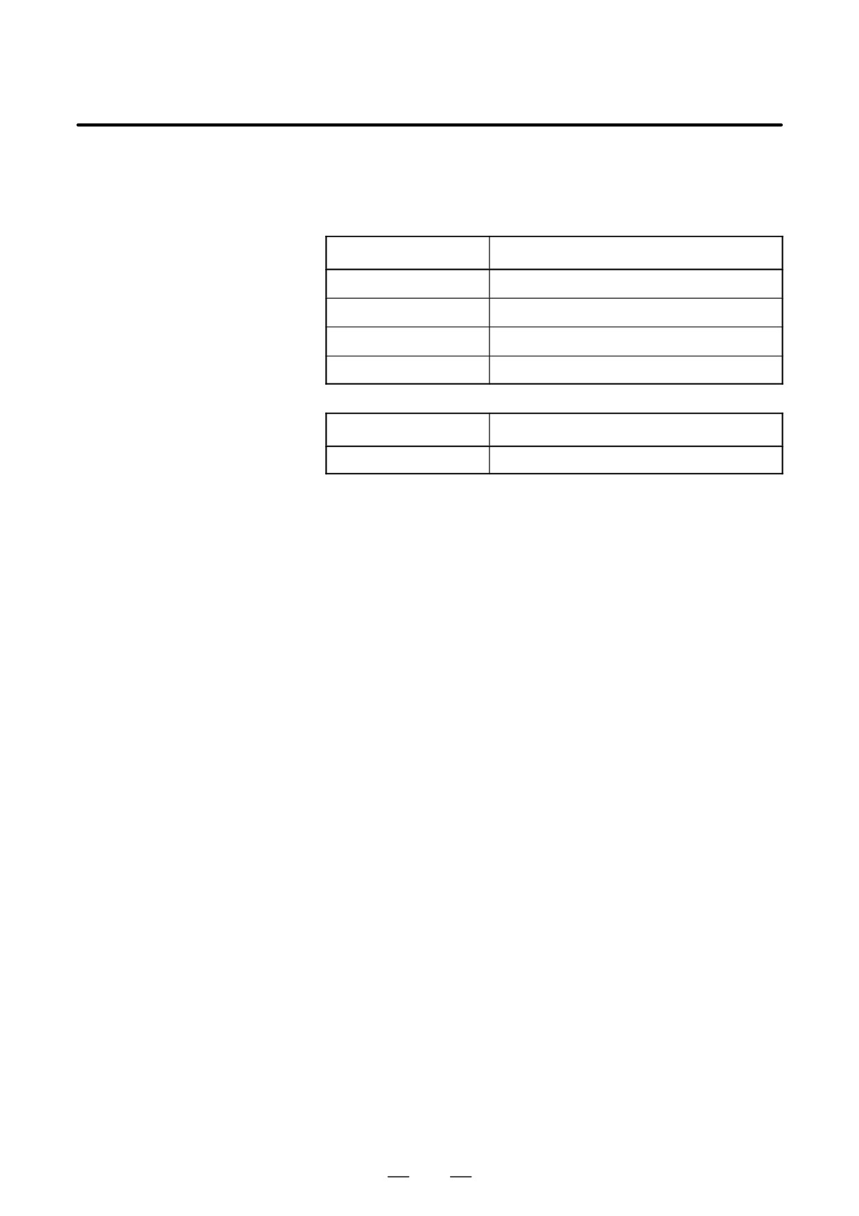
For an explanation of the following spindle alarms, refer to the FANUC
11.42
SERVO MOTOR αi series Maintenance Manual (B-65285EN) or
SPINDLE ALARMS
FANUC SERVO MOTOR α series Maintenance Manual (B-65165E).
Number
Contents
7101 to 7199
Spindle 1 alarm (SPM display 01 to 99)
7201 to 7299
Spindle 2 alarm (SPM display 01 to 99)
7301 to 7399
Spindle 3 alarm (SPM display 01 to 99)
7401 to 7499
Spindle 4 alarm (SPM display 01 to 99)
Number
Contents
9001 to later: Spindle_n
n-th spindle alarm (SPM display 01 or larger)
832
APPENDIX
B-63525EN/02
APPENDIX
A. ALARM LIST
ALARM LIST
A
A.1 LIST OF ALARM CODES (CNC)
836
A.2 LIST OF ALARMS (PMC)
875
A.3 ALARM LIST (SERIAL SPINDLE)
900
A.4 ERROR CODES (SERIAL SPINDLE)
912
835
A. ALARM LIST
APPENDIX
B-63525EN/02
A.1
LIST OF ALARM
CODES (CNC)
(1) Program errors /Alarms on program and operation (P/S alarm)
Number
Message
Contents
000
PLEASE TURN OFF POWER
A parameter which requires the power off was input, turn off power.
001
TH PARITY ALARM
TH alarm (A character with incorrect parity was input).
Correct the tape.
002
TV PARITY ALARM
TV alarm (The number of characters in a block is odd). This alarm will
be generated only when the TV check is effective.
003
TOO MANY DIGITS
Data exceeding the maximum allowable number of digits was input.
(Refer to the item of max. programmable dimensions.)
004
ADDRESS NOT FOUND
A numeral or the sign “ - ” was input without an address at the beginning
of a block. Modify the program .
005
NO DATA AFTER ADDRESS
The address was not followed by the appropriate data but was followed
by another address or EOB code. Modify the program.
006
ILLEGAL USE OF NEGATIVE SIGN
Sign “ - ” input error (Sign “ - ” was input after an address with which it
cannot be used. Or two or more “ - ” signs were input.)
Modify the program.
007
ILLEGAL USE OF DECIMAL POINT
Decimal point “ . ” input error (A decimal point was input after an address
with which it can not be used. Or two decimal points were input.)
Modify the program.
009
ILLEGAL ADDRESS INPUT
Unusable character was input in significant area.
Modify the program.
010
IMPROPER G-CODE
An unusable G code or G code corresponding to the function not pro-
vided is specified. Modify the program.
011
NO FEEDRATE COMMANDED
Feedrate was not commanded to a cutting feed or the feedrate was in-
adequate. Modify the program.
CAN NOT COMMAND G95
A synchronous feed is specified without the option for threading / syn-
(M series)
chronous feed.
ILLEGAL LEAD COMMAND
In variable lead threading, the lead incremental and decremental out-
014
(T series)
putted by address K exceed the maximum command value or a com-
mand such that the lead becomes a negative value is given.
Modify the program.
TOO MANY AXES COMMANDED
An attempt was made to move the machine along the axes, but the num-
(M series)
ber of the axes exceeded the specified number of axes controlled simul-
taneously. Modify the program.
TOO MANY AXES COMMANDED
An attempt has been made to move the tool along more than the maxi-
(T series)
mum number of simultaneously controlled axes. Alternatively, no axis
015
movement command or an axis movement command for two or more
axes has been specified in the block containing the command for skip
using the torque limit signal (G31 P99/98). The command must be ac-
companied with an axis movement command for a single axis, in the
same block.
020
OVER TOLERANCE OF RADIUS
In circular interpolation (G02 or G03), difference of the distance between
the start point and the center of an arc and that between the end point
and the center of the arc exceeded the value specified in parameter No.
3410.
021
ILLEGAL PLANE AXIS COMMAN-
An axis not included in the selected plane (by using G17, G18, G19) was
DED
commanded in circular interpolation. Modify the program.
022
NO CIRCLE RADIUS
The command for circular interpolation lacks arc radius R or coordinate
I, J, or K of the distance between the start point to the center of the arc.
836
B-63525EN/02
APPENDIX
A. ALARM LIST
Number
Message
Contents
023
ILLEGAL RADIUS COMMAND
In circular interpolation by radius designation, negative value was com-
(T series)
manded for address R. Modify the program.
025
CANNOT COMMAND F0 IN G02/G03
F0 (fast feed) was instructed by F1 -digit column feed in circular inter-
(M series)
polation. Modify the program.
027
NO AXES COMMANDED IN
No axis is specified in G43 and G44 blocks for the tool length offset type
G43/G44 (M series)
C.
Offset is not canceled but another axis is offset for the tool length offset
type C. Modify the program.
028
ILLEGAL PLANE SELECT
In the plane selection command, two or more axes in the same direction
are commanded.
Modify the program.
ILLEGAL OFFSET VALUE
The offset values specified by H code is too large.
(M series)
Modify the program.
029
ILLEGAL OFFSET VALUE
The offset values specified by T code is too large.
(T series)
Modify the program.
ILLEGAL OFFSET NUMBER
The offset number specified by D/H code for tool length offset, cutter
(M series)
compensation, or three-dimensional tool offset is too large. Alternative-
ly, the number of an additional workpiece coordinate system specified
030
with the P code is too large. Modify the program.
ILLEGAL OFFSET NUMBER
The offset number in T function specified for tool offset is tool large.
(T series)
Modify the program.
031
ILLEGAL P COMMAND IN G10
In setting an offset amount by G10, the offset number following address
P was excessive or it was not specified.
Modify the program.
032
ILLEGAL OFFSET VALUE IN G10
In setting an offset amount by G10 or in writing an offset amount by sys-
tem variables, the offset amount was excessive.
NO SOLUTION AT CRC
A point of intersection cannot be determined for cutter compensation.
(M series)
Modify the program.
033
NO SOLUTION AT CRC
A point of intersection cannot be determined for tool nose radius com-
(T series)
pensation. Modify the program.
NO CIRC ALLOWED IN ST-UP /EXT
The start up or cancel was going to be performed in the G02 or G03
BLK (M series)
mode in cutter compensation C. Modify the program.
034
NO CIRC ALLOWED IN ST-UP /EXT
The start up or cancel was going to be performed in the G02 or G03
BLK (T series)
mode in tool nose radius compensation. Modify the program.
CAN NOT COMMANDED G39
G39 is commanded in cutter compensation B cancel mode or on the
(M series)
plane other than offset plane. Modify the program.
035
CAN NOT COMMANDED G31
Skip cutting (G31) was specified in tool nose radius compensation
(T series)
mode. Modify the program.
036
CAN NOT COMMANDED G31
Skip cutting (G31) was specified in cutter compensation mode.
(M series)
Modify the program.
CAN NOT CHANGE PLANE IN CRC
G40 is commanded on the plane other than offset plane in cutter com-
(M seires)
pensation B. The plane selected by using G17, G18 or G19 is changed
037
in cutter compensation C mode. Modify the program.
CAN NOT CHANGE PLANE IN NRC
The offset plane is switched in tool nose radius compensation.
(T seires)
Modify the program.
INTERFERENCE IN CIRCULAR
Overcutting will occur in cutter compensation C because the arc start
BLOCK (M seires)
point or end point coincides with the arc center.
Modify the program.
038
INTERFERENCE IN CIRCULAR
Overcutting will occur in tool nose radius compensation because the arc
BLOCK (T series)
start point or end point coincides with the arc center.
Modify the program.
837
A. ALARM LIST
APPENDIX
B-63525EN/02
Number
Message
Contents
039
CHF/CNR NOT ALLOWED IN NRC
Chamfering or corner R was specified with a start-up, a cancel, or
(T series)
switching between G41 and G42 in tool nose radius compensation. The
program may cause overcutting to occur in chamfering or corner R.
Modify the program.
040
INTERFERENCE IN G90/G94
Overcutting will occur in tool nose radius compensation in canned cycle
BLOCK (T series)
G90 or G94. Modify the program.
INTERFERENCE IN CRC
Overcutting will occur in cutter compensation C. Two or more blocks are
(M seires)
consecutively specified in which functions such as the auxiliary function
and dwell functions are performed without movement in the cutter com-
041
pensation mode. Modify the program.
INTERFERENCE IN NRC
Overcutting will occur in tool nose radius compensation.
(T seires)
Modify the program.
042
G45/G48 NOT ALLOWED IN CRC
Tool offset (G45 to G48) is commanded in cutter compensation. Modify
(M series)
the program.
044
G27-G30 NOT ALLOWED IN FIXED
One of G27 to G30 is commanded in canned cycle mode.
CYC (M series)
Modify the program.
045
ADDRESS Q NOT FOUND
In canned cycle G73/G83, the depth of each cut (Q) is not specified. Al-
(G73/G83) (M series)
ternatively, Q0 is specified. Correct the program.
046
ILLEGAL REFERENCE RETURN
Other than P2, P3 and P4 are commanded for 2nd, 3rd and 4th refer-
COMMAND
ence position return command.
047
ILLEGAL AXIS SELECT
Two or more parallel axes (in parallel with a basic axis) have been speci-
fied upon start-up of three-dimensional tool compensation or three-di-
mensional coordinate conversion.
048
BASIC 3 AXIS NOT FOUND
Start-up of three-dimensional tool compensation or three-dimensional
coordinate conversion has been attempted, but the three basic axes
used when Xp, Yp, or Zp is omitted are not set in parameter No. 1022.
049
ILLEGAL OPERATION (G68/G69)
The commands for three-dimensional coordinate conversion (G68,
(M series)
G69) and tool length compensation (G43, G44, G45) are not nested.
Modify the program.
050
CHF/CNR NOT ALLOWED IN THRD
Optional chamfering or corner R is commanded in the thread cutting
BLK (M series)
block.
Modify the program.
CHF/CNR NOT ALLOWED IN THRD
Chamfering or corner R is commanded in the thread cutting block.
BLK(T series)
Modify the program.
051
MISSING MOVE AFTER CHF/CNR
Improper movement or the move distance was specified in the block
(M series)
next to the optional chamfering or corner R block.
Modify the program.
MISSING MOVE AFTER CHF/CNR
Improper movement or the move distance was specified in the block
(T series)
next to the chamfering or corner R block.
Modify the program.
CODE IS NOT G01 AFTER CHF/CNR
The block next to the chamfering or corner R block is not G01,G02 or
(M series)
G03.
Modify the program.
052
CODE IS NOT G01 AFTER CHF/CNR
The block next to the chamfering or corner R block is not G01.
(T series)
Modify the program.
TOO MANY ADDRESS COMMANDS
For systems without the arbitary angle chamfering or corner R cutting,
(M series)
a comma was specified. For systems with this feature, a comma was fol-
lowed by something other than R or C Correct the program.
053
TOO MANY ADDRESS COMMANDS
In the chamfering and corner R commands, two or more of I, K and R
(T seires)
are specified. Otherwise, the character after a comma(“,”) is not C or R
in direct drawing dimensions programming. Modify the program.
NO TAPER ALLOWED AFTER CHF/
A block in which chamfering in the specified angle or the corner R was
054
CNR (T series)
specified includes a taper command. Modify the program.
838
B-63525EN/02
APPENDIX
A. ALARM LIST
Number
Message
Contents
MISSING MOVE VALUE IN CHF/CNR
In the arbitrary angle chamfering or corner R block, the move distance
(M series)
is less than chamfer or corner R amount.
055
MISSING MOVE VALUE IN CHF/CNR
In chamfering or corner R block, the move distance is less than chamfer
(T series)
or corner R amount.
056
NO END POINT & ANGLE IN CHF/
Neither the end point nor angle is specified in the command for the block
CNR (T series)
next to that for which only the angle is specified (A). In the chamfering
comman, I(K) is commanded for the X(Z) axis.
057
NO SOLUTION OF BLOCK END
Block end point is not calculated correctly in direct dimension drawing
(T series)
programming.
END POINT NOT FOUND
In a arbitrary angle chamfering or corner R cutting block, a specified axis
(M series)
is not in the selected plane. Correct the program.
058
END POINT NOT FOUND
Block end point is not found in direct dimension drawing programming.
(T series)
059
PROGRAM NUMBER NOT FOUND
In an external program number search, a specified program number
was not found. Otherwise, a program specified for searching is being
edited in background processing. Alternatively, the program with the
program number specified in a one-touch macro call is not found in
memory. Check the program number and external signal. Or discontin-
ue the background eiting.
060
SEQUENCE NUMBER NOT FOUND
Commanded sequence number was not found in the sequence number
search. Check the sequence number.
061
ADDRESS P/Q NOT FOUND IN
Address P or Q is not specified in G70, G71, G72, or G73 command.
G70-G73 (T series)
Modify the program.
062
ILLEGAL COMMAND IN G71-G76
1. The depth of cut in G71 or G72 is zero or negative value.
(T series)
2. The repetitive count in G73 is zero or negative value.
3. the negative value is specified to ∆i or ∆k is zero in G74 or G75.
4. A value other than zero is specified to address U or W though ∆i or
∆k is zero in G74 or G75.
5. A negative value is specified to ∆d, thoughthe relief direction in G74
or G75 is determined.
6. Zero or a negative value is specified to the height of thread or depth
of cut of first time in G76.
7. The specified minimum depth of cut in G76 is greater than the height
of thread.
8. An unusable angle of tool tip is specified in G76.
Modify the program.
063
SEQUENCE NUMBER NOT FOUND
The sequence number specified by address P in G70, G71, G72, or G73
(T series)
command cannot be searched. Modify the program.
064
SHAPE PROGRAM NOT MONOTO-
A target shape which cannot be made by monotonic machining was
NOUSLY (T series)
specified in a repetitive canned cycle (G71 or G72).
065
ILLEGAL COMMAND IN G71-G73
1. G00 or G01 is not commanded at the block with the sequence num-
(T series)
ber which is specified by address P in G71, G72, or G73 command.
2. Address Z(W) or X(U) was commanded in the block with a sequence
number which is specified by address P in G71 or G72, respectively.
Modify the program.
066
IMPROPER G-CODE IN G71-G73
An unallowable G code was commanded beween two blocks specified
(T series)
by address P in G71, G72, or G73. Modify the program.
067
CAN NOT ERROR IN MDI MODE
G70, G71, G72, or G73 command with address P and Q.
(T series)
Modify the program.
839
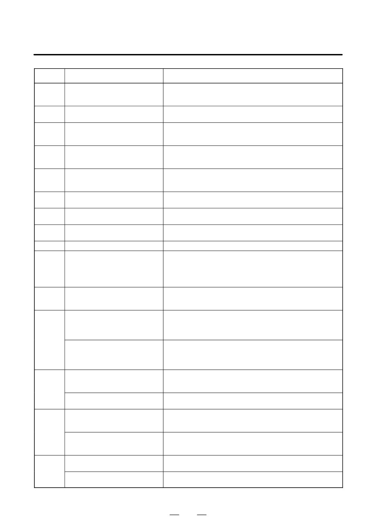
A. ALARM LIST
APPENDIX
B-63525EN/02
Number
Message
Contents
069
FORMAT ERROR IN G70-G73
The final move command in the blocks specified by P and Q of G70,
(T series)
G71, G72, and G73 ended with chamfering or corner R.
Modify the program.
070
NO PROGRAM SPACE IN MEMORY
The memory area is insufficient.
Delete any unnecessary programs, then retry.
071
DATA NOT FOUND
The address to be searched was not found. Or the program with speci-
fied program number was not found in program number search.
Check the data.
072
TOO MANY PROGRAMS
The number of programs to be stored exceeded 63 (basic), 125 (option),
200 (option), 400 (option) or 1000 (option). Delete unnecessary pro-
grams and execute program registeration again.
073
PROGRAM NUMBER ALREADY IN
The commanded program number has already been used.
USE
Change the program number or delete unnecessary programs and
execute program registeration again.
074
ILLEGAL PROGRAM NUMBER
The program number is other than 1 to 9999.
Modify the program number.
075
PROTECT
An attempt was made to register a program whose number was pro-
tected.
076
ADDRESS P NOT DEFINED
Address P (program number) was not commanded in the block which
includes an M98, G65, or G66 command. Modify the program.
077
SUB PROGRAM NESTING ERROR
The subprogram was called in five folds. Modify the program.
078
NUMBER NOT FOUND
A program number or a sequence number which was specified by ad-
dress P in the block which includes an M98, M99, M65 or G66 was not
found. The sequence number specified by a GOTO statement was not
found. Otherwise, a called program is being edited in background pro-
cessing. Correct the program, or discontinue the background editing.
079
PROGRAM VERIFY ERROR
In memory or program collation,a program in memory does not agree
with that read from an external I/O device. Check both the programs in
memory and those from the external device.
G37 ARRIVAL SIGNAL NOT
In the automatic tool length measurement function (G37), the measure-
ASSERTED
ment position reach signal (XAE, YAE, or ZAE) is not turned on within
(M series)
an area specified in parameter 6254 6255 (value ε).
This is due to a setting or operator error.
080
G37 ARRIVAL SIGNAL NOT
In the automatic tool compensation function (G36, G37), the measure-
ASSERTED
ment position reach signal (XAE or ZAE) is not turned on within an area
(T series)
specified in parameter 6254 (value ε).
This is due to a setting or operator error.
OFFSET NUMBER NOT FOUND IN
Tool length automatic measurement (G37) was specified without a H
G37
code. (Automatic tool length measurement function) Modify the pro-
(M series)
gram.
081
OFFSET NUMBER NOT FOUND IN
Automatic tool compensation (G36, G37) was specified without a T
G37 (T series)
code. (Automatic tool compensation function) Modify the program.
H-CODE NOT ALLOWED IN G37
H code and automatic tool compensation (G37) were specified in the
(M series)
same block. (Automatic tool length measurement function) Modify the
program.
082
T-CODE NOT ALLOWED IN G37
T code and automatic tool compensation (G36, G37) were specified in
(T series)
the same block. (Automatic tool compensation function)
Modify the program.
ILLEGAL AXIS COMMAND IN G37
In automatic tool length measurement, an invalid axis was specified or
(M series)
the command is incremental. Modify the program.
083
ILLEGAL AXIS COMMAND IN G37
In automatic tool compensation (G36, G37), an invalid axis was speci-
(T series)
fied or the command is incremental. Modify the program.
840
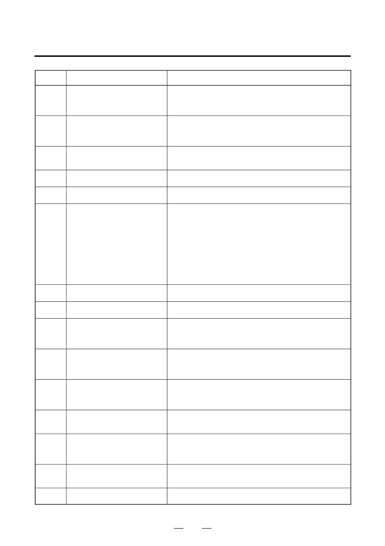
B-63525EN/02
APPENDIX
A. ALARM LIST
Number
Message
Contents
085
COMMUNICATION ERROR
When entering data in the memory by using Reader / Puncher interface,
an overrun, parity or framing error was generated. The number of bits
of input data or setting of baud rate or specification No. of I/O unit is in-
correct.
086
DR SIGNAL OFF
When entering data in the memory by using Reader / Puncher interface,
the ready signal (DR) of reader / puncher was turned off.
Power supply of I/O unit is off or cable is not connected or a P.C.B. is de-
fective.
087
BUFFER OVERFLOW
When entering data in the memory by using Reader / Puncher interface,
though the read terminate command is specified, input is not interrupted
after 10 characters read. I/O unit or P.C.B. is defective.
088
LAN FILE TRANS ERROR
File data transfer via OSI-ETHERNET has been stopped due to a trans-
(CHANNEL-1)
fer error.
089
LAN FILE TRANS ERROR
File data transfer via OSI-ETHERNET has been stopped due to a trans-
(CHANNEL-2)
fer error.
090
REFERENCE RETURN
1. The reference position return cannot be performed normally be-
INCOMPLETE
cause the reference position return start point is too close to the ref-
erence position or the speed is too slow. Separate the start point far
enough from the reference position, or specify a sufficiently fast
speed for reference position return.
2. During reference position return with the absolute-position detector,
if this alarm occurs even though condition 1 is satisfied, do the fol-
lowing:
After turning the servo motor for the axis at least one turn, turn the
power off and then on again. Then perform reference position re-
turn.
091
REFERENCE RETURN
Manual reference position return cannot be performed when automatic
INCOMPLETE
operation is halted.
092
AXES NOT ON THE REFERENCE
The commanded axis by G27 (Reference position return check) did not
POINT
return to the reference position.
094
P TYPE NOT ALLOWED
P type cannot be specified when the program is restarted. (After the au-
(COORD CHG)
tomatic operation was interrupted, the coordinate system setting opera-
tion was performed.)
Perform the correct operation according to th operator’s manual.
095
P TYPE NOT ALLOWED
P type cannot be specified when the program is restarted.
(After the
(EXT OFS CHG)
automatic operation was interrupted, the external workpiece offset
amount changed.)
Perform the correct operation according to th operator’s manual.
096
P TYPE NOT ALLOWED
P type cannot be specified when the program is restarted. (After the au-
(WRK OFS CHG)
tomatic operation was interrupted, the workpiece offset amount
changed.)
Perform the correct operation according to the operator’s manual.
097
P TYPE NOT ALLOWED
P type cannot be directed when the program is restarted. (After power
(AUTO EXEC)
ON, after emergency stop or P / S 94 to 97 reset, no automatic operation
is performed.) Perform automatic operation.
098
G28 FOUND IN SEQUENCE
A command of the program restart was specified without the reference
RETURN
position return operation after power ON or emergency stop, and G28
was found during search.
Perform the reference position return.
099
MDI EXEC NOT ALLOWED
After completion of search in program restart, a move command is given
AFT. SEARCH
with MDI. Move axis before a move command or don’t interrupt MDI op-
eration.
100
PARAMETER WRITE ENABLE
On the PARAMETER(SETTING) screen, PWE(parameter writing en-
abled) is set to 1. Set it to 0, then reset the system.
841