FANUC Series 16i/160i/160is-MODEL B, Series 18i/180i/180is-MODEL B, Series 21i/210i/210is-MODEL B. MAINTENANCE MANAUL - page 27
11. TROUBLESHOOTING
B-63525EN/02
[For the stand-alone
type]
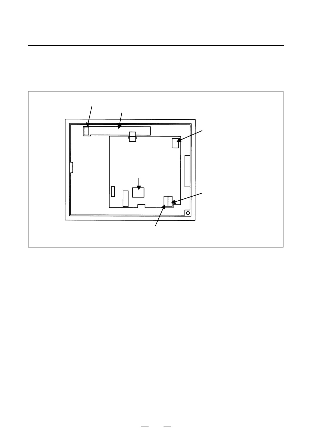
D Power supply of the LCD
Check that the power cable is connected to the connector CP1A of the
unit
LCD unit.
Connector for connecting the backlight cable
Inverter printed circuit board
Connector for connecting
the LCD cable
LCD control printed
circuit board
Optical cable
COP20B
24 V input
CP1A
For 24 V branch
CP1B
D LED display
Referring to the hardware chapter, check the LED on/off status of the main
CPU board.
If the main CPU board has started up normally and the LED display
indicates normal operation, a probable cause is a fault of the display
system, such as the cable of the LCD unit not connected or a defective
inverter board.
If the LED display is locked in the middle of the startup process, the
probable causes include defective hardware (or installation failure) and
the necessary software not installed.
D Optical cable
Check that the optical cable is free from excessive force and that it is not
excessively bent. Check that the optical cable is connected firmly.
If no problems are found with the connection of the optical cable, replace
the optical cable.
D Connection on the LCD
Check that the backlight and LCD cables are connected firmly to the
unit
corresponding connectors.
These cables are connected before shipment from FANUC. This check
is, however, required because the cables may be disconnected during
maintenance.
D Display control card
Check that the display control card installed on the main CPU board is
engaged with the connector. If it is engaged properly, replace this card.
D LCD unit
Replace the LCD unit or the control printed circuit board located at the
rear of the LCD unit
752
B-63525EN/02
11.TROUBLESHOOTING
D Main CPU board
If any of the above actions does not solve the problem, replace the main
CPU board and the CPU card.
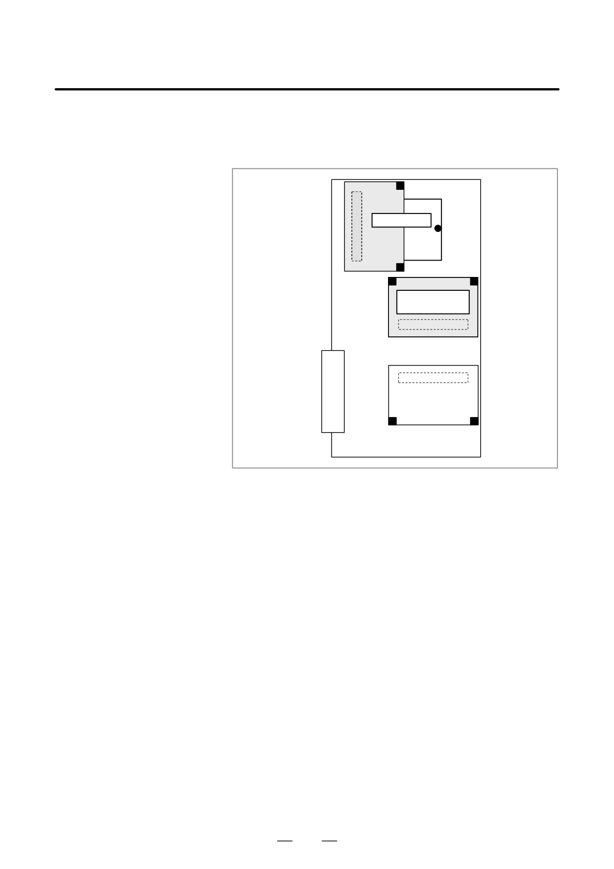
D Installation positions of
the display control card
and the CPU card
CPU card
Display control
card
753
11. TROUBLESHOOTING
B-63525EN/02
11.8
THE DISPLAY ON
THE LCD UNIT
FLASHES
Causes and actions
This situation can occur only with the stand-alone type.
If a break is detected in the optical cable (HSSB) that connects the LCD
unit to the main CPU board, the display on the LCD unit flashes.
The same situation occurs if the main CPU board is turned off while the
power is on.
D Power supply of the
The display on the LCD unit flashes if the main CPU board is turned off,
main CPU board
with the LCD kept on, while the power is on.
D Break of the optical
Check that the optical cable is free from excessive force and that it is not
cable
excessively bent.
If no problems are found with the connection of the cable, replace the
optical cable.
D Display control card
Replace the display control card installed on the main CPU board.
D LCD unit
Replace the LCD unit or the control printed circuit board located at the
rear of the LCD unit
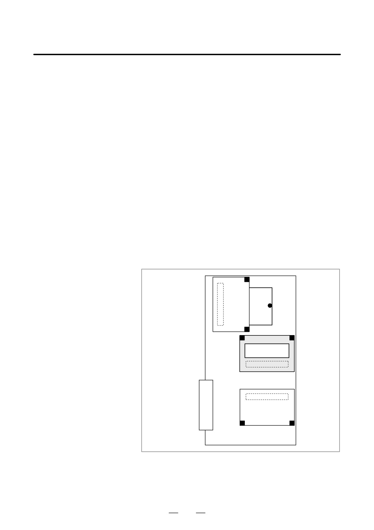
D Installation position of
the display control card
Display control
card
754
B-63525EN/02
11.TROUBLESHOOTING
11.9
INPUT FROM AND
OUTPUT TO I/O
DEVICES CANNOT
BE PERFORMED
INPUT/
OUTPUT CANNOT BE
PERFORMED
PROPERLY
Causes and actions
If the I/O Link is not established, if the signals from an I/O device cannot
be input normally to the CNC, or if the signals from the CNC cannot be
output to an I/O device, the probable causes include the following:
D The I/O device is not turned on, or the power supply is not at the
appropriate voltage.
D The I/O Link cable is not connected correctly or appropriately.
D The input/output signals are not connected correctly.
D I/O Link allocation is not performed, or is not performed properly.
D PMC alarm NO I/O
If “NO I/O DEVICE” is displayed on the alarm screen of the PMC, no I/O
DEVICE
devices are recognized.
D IOCHK screen of the
By selecting [PMCDGN], [IOCHK], and [IOLNK] in this order from the
PMC
PMC screen, the I/O devices recognized by the CNC are displayed. From
this screen, the devices that are connected normally can be determined.
Screen display example
GROUP ID
KIND OF UNIT00
00
A9
I/O MODULE01
01
A8
OTHER UNIT
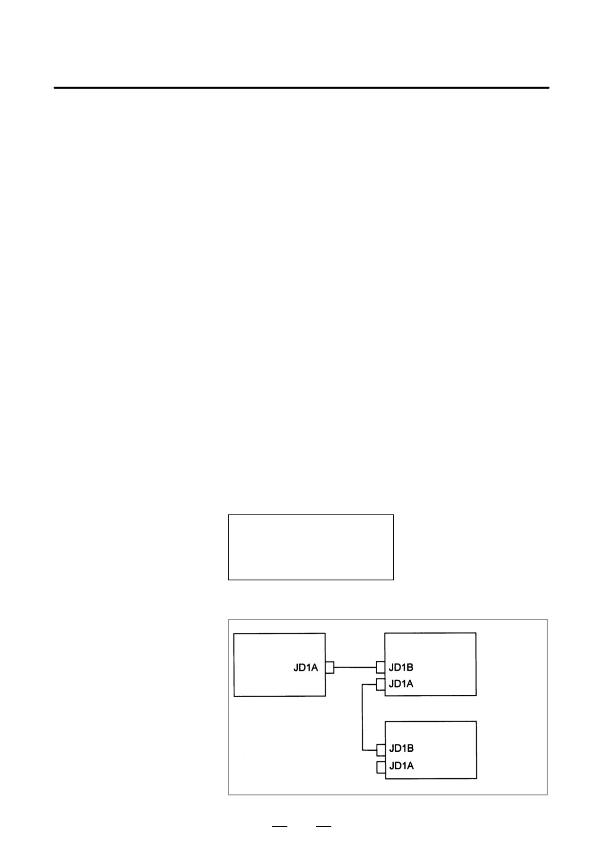
This example indicates that the I/O Link is as shown in the figure below.
I/O module for
Control unit
connector panel
Group 0
Operator’s panel
I/O module
Group 1
755
11. TROUBLESHOOTING
B-63525EN/02
D Checking the power
Check that the connected I/O devices are connected properly to the power
supplies of the I/O
supplies and that the voltages are as prescribed.
devices
Check that the power-on sequence is correct.
Time at which an I/O device is to be turned on
Before the CNC is turned on or within 500 ms after the CNC is
turned on
When the CNC is turned off, the I/O devices must also be turned off.
(Otherwise, the I/O Link may not be established the next time the CNC
is turned on.)
D Connection of cables
As in the example shown on the previous page, I/O Link cables are used
to connect JD1As and JD1Bs.
JD1A represents an upper unit while JD1B represents a lower unit.
Check that the cables are connected correctly.
D Connection of I/O signals
Check that the input/output signals to be connected to each I/O device are
connected correctly.
For operator’s panel I/O modules and for connector panel I/O modules,
also check that the 0 V or +24 V input signal is connected to the common
pin and that the +24 V output signal is connected to the DO common pin.
D I/O Link allocation
Check that I/O Link allocation has been performed correctly.
Selecting [EDIT] and then [MODULE] from the PMC screen causes the
allocation edit screen to be displayed.
After editing allocation, write the changes to the FROM on the [I/O]
screen. Otherwise, the changes will be lost when the power is turned off.
The checking of allocation requires a Ladder editing card.
756
B-63525EN/02
11.TROUBLESHOOTING
11.10
IN A CONNECTOR
PANEL I/O UNIT,
DATA IS INPUT TO
AN UNEXPECTED
ADDRESS
If data is input to an invalid address in a connector panel I/O unit (for
example, data that should be input to X004 is actually input to X010 in
a connector panel I/O unit), the most likely causes are as follows:
(1) The I/O Link allocation is wrong.
→ Perform the check described in Section 11.4.
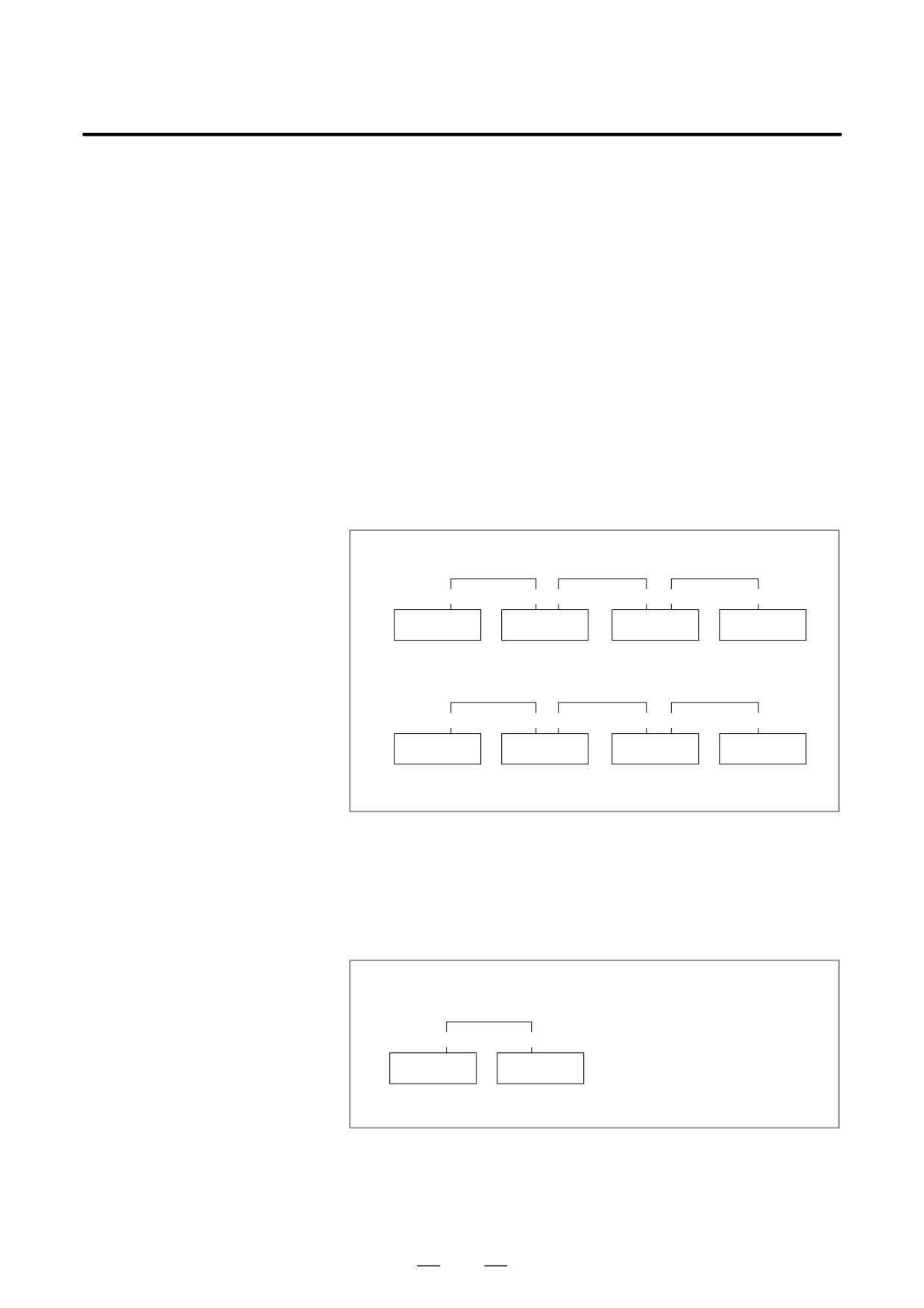
(2) The unit-to-unit cables
(CA52-to-CA53) are not connected
correctly.
If the connection is wrong, expansion unit 1 is allocated the address
of expansion unit 3, as shown below.
→ Connect the unit-to-unit cables as shown below:
Correct connection (the allocation starts with X0)
CA52
CA53 CA52
CA53 CA52
CA53
Basic
Expansion 1
Expansion 2
Expansion 3
X0-2
X3-5
X6-8
X9-11
Incorrect connection (the allocation starts with X0)
CA52
CA52 CA53
CA53 CA52
CA53
Basic
Expansion 1
Expansion 2
Expansion 3
X0-2
X9-11
X6-8
X3-5
(3) The setting of the rotary switch on an expansion unit is wrong
If the rotary switch is set to 1, one unit number is skipped. If set to 2,
two unit numbers are skipped. Usually, the setting must be 0.
(For
those units without a rotary switch, unit numbers cannot be skipped.)
→ See the following example and refer to the “FANUC Series
16i/18i/21i-B Connection Manual (Hardware)” (B-63523EN).
Example)
Rotary switch setting on expansion unit 1=1
CA52
CA53
Basic
Expansion 1
X0-2
X6-8
<=X3 to X5 are skipped.
757
11. TROUBLESHOOTING
B-63525EN/02
The most likely cause is that power is not being supplied to the expansion
11.11
unit.
IN A CONNECTOR
→ Check whether 24-V power is supplied to 18P and 50P of the
PANEL I/O UNIT, NO
expansion unit, DI and DO signals are not input and output.
DATA IS OUTPUT TO
→ Check whether 24-V power is supplied to 1P and 3P of the expansion
AN EXPANSION UNIT
unit, when DI signals are input and DO signals are not output.
758
B-63525EN/02
11.TROUBLESHOOTING
11.12
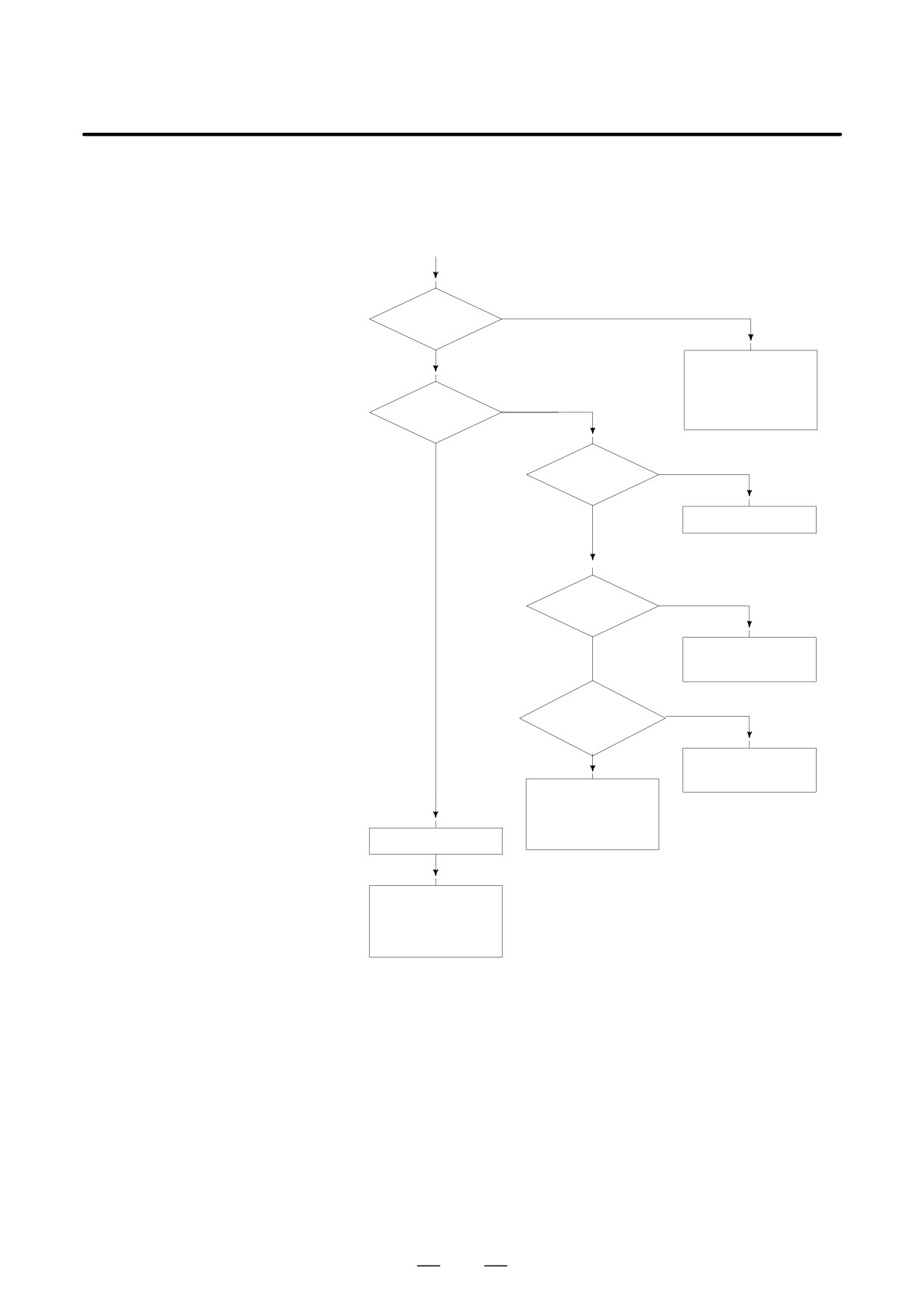
ALARM 85 TO 87
(READER/PUNCHER
(START)
INTERFACE ALARM)
YES
Alarm 85?
NO
· Check baud rate
and other I/O pa
rameters
YES
· I/O device is
Alarm 86?
faulty
NO
Is I/O
NO
parameter
correct?
YES
Set correct parameters
OFF
Is power of I/O ?
ON
Turn on I/O device
NO
Is cable
connection right?
YES
Connect the cable
· I/O device is faulty
· Mother board or
serial communica-
tion board is faulty
Alarm 87?
· I/O device is faulty
· Mother board or
serial communica-
tion board is faulty
Causes
(a) Parameters on reader/puncher interface are not correct.
Check the following setting data and parameters.
(b) External I/O device or host computer is faulty.
(c) Mother board or serial communication board is faulty.
(d) Cable between NC and I/O device is faulty.
Countermeasures
(a) Parameters on reader/puncher interface are not correct.
Check the following setting data and parameters:
<Setting>
PUNCH CODE=0 OR 1 (0: EIA,1:ISO)
Select ISO or EIA according to the type of I/O device.
If punch code does not match, alarm 86 will generate.
759
11. TROUBLESHOOTING
B-63525EN/02
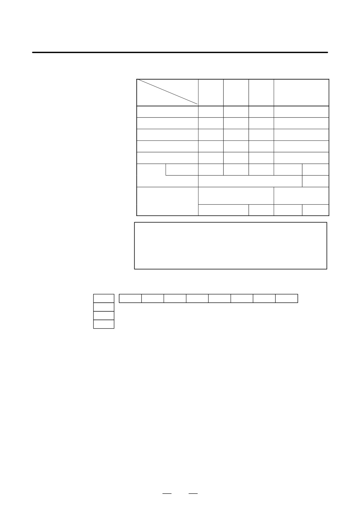
<Parameter>
Value of parame-
ter 0020
0
1
2
3
Function
Feed
0101#7
0111#7
0121#7
0131#7
Data input code
0101#3
0111#3
0121#3
0131#3
Stop bit
0101#0
0111#0
0121#0
0131#0
Type of I/O device
102
112
122
132
Baud rate
103
113
123
133
Commu-
0135#3
-
-
-
0
1
nication
method
RS-232C
RS-422
SERIAL COMMUNICA-
MOTHER BOARD
TION BOARD
Connector
JD36A
JD36B
JD28A
JD6A
NOTE
1
Numbers in the table indicate parameters and bit numbers.
Example) 101#7: bit7 of parameter 101.
2
For data communications by RS-422, refer to parameters
134 and 135.
#7
#6
#5
#4
#3
#2
#1
#0
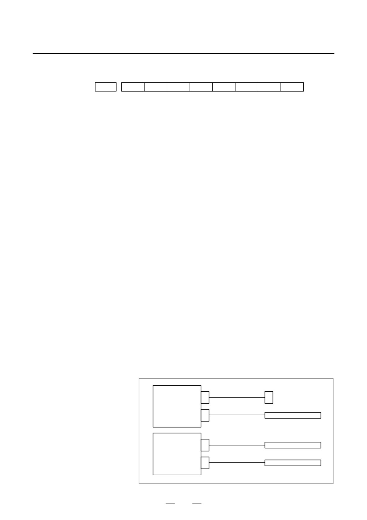
0101
NFD
ASI
SB2
0111
0121
0131
#7(NFD)
0 : Feed is output before and after data in data output (FANUC PPR)
1 : Feed is not output (standard).
#3(ASI)
0 : Data input code is EIA or ISO (automatic recognition)
1 : Data input code is ASCII.
#0(SB2)
0 : No. of stop bits is 1.
1 : No. of stop bits is 2.
760
B-63525EN/02
11.TROUBLESHOOTING
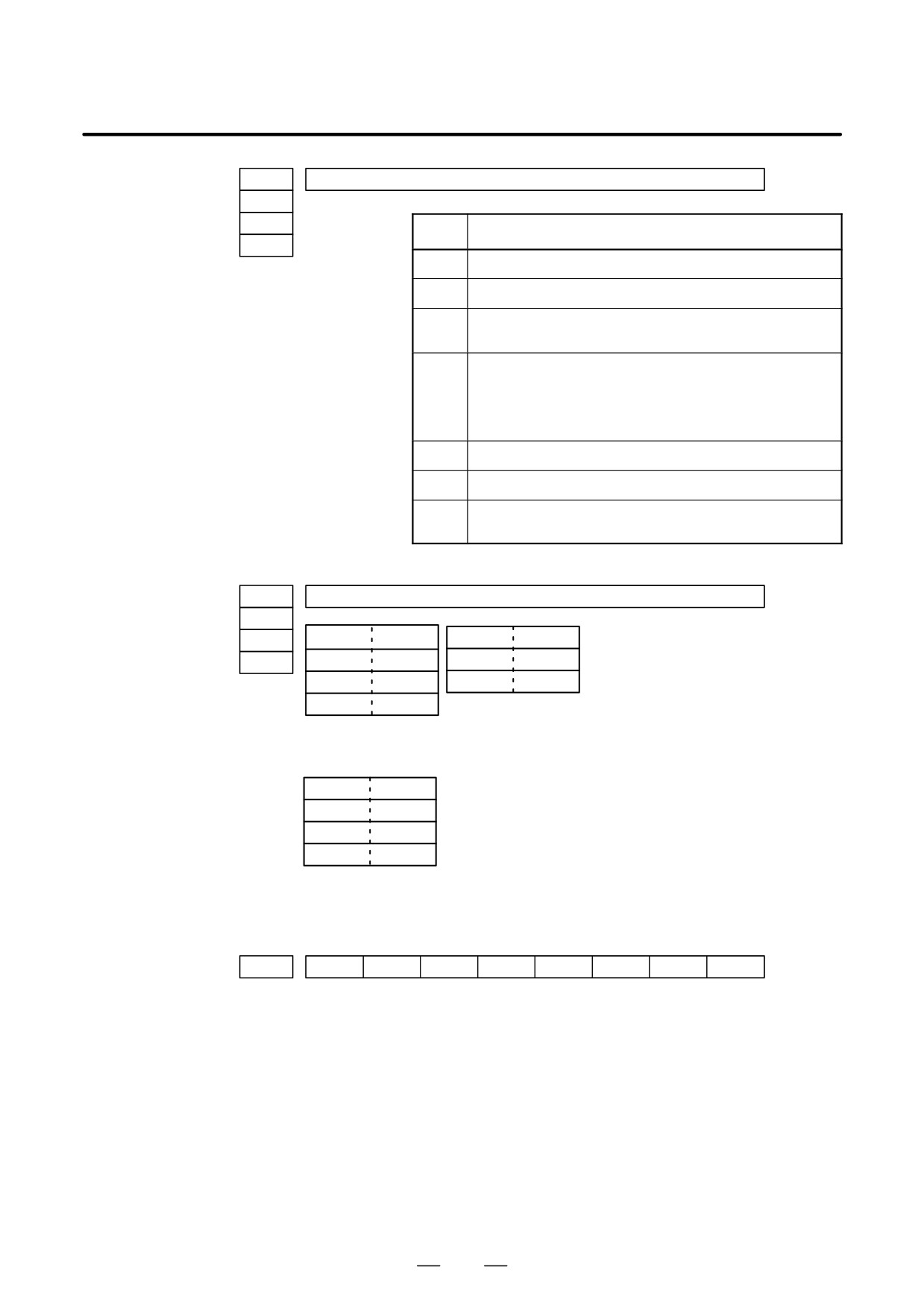
0102
Type of I/O device
0112
0122
Value
TYPE OF I/O DEVICE
0132
0
RS-232-C (if the following units are not used)
1
FANUC CASSETTE B1/B2 (bubble cassette)
2
FANUC CASSETTE F1 (Old type FLOPPY CASSETTE ADAP-
TOR)
3
FANUC PROGRAM FILE Mate,
FANUC FA CARD ADAPTOR
FANUC FLOPPY CASSETTE ADAPTOR,
FANUC SYSTEM P-MODEL H,
FANUC Handy File
4
Not used
5
Portable tape reader
6
FANUC PPR, FANUC SYSTEM P-MODEL G,
FANUC SYSTEM P-MODEL H
0103
Baud rete
0113
0123
Value
Baud rate
10
4800
0133
7
600
11
9600
8
1200
12
19200
9
2400
When bit#3 of parameter no. 0135=1 (RS-422 interface), the following
setting is also available.
Value
Baud rate
13
38400
14
76800
15
86400
Check the following parameters also, when parameter no.0020 is 3.
#7
#6
#5
#4
#3
#2
#1
#0
0134
CLK
NCD
SYN
PRY
#5(CLK)
0 : Internal clock is used for baud rate clock of RS-422 interface.
1 : External clock is used for baud rate clock of RS-422 interface.
#4(NCD)
0 : CD (signal quality detection) of RS-232C interface is checked.
1 : CD (signal quality detection) of RS-232C interface is not checked.
#2(SYN)
0 : In protocol B, NC reset/alarm is not informed to the host.
1 : In protocol B, NC reset/alarm is informed to the host by SYN and
NAK code.
#1(PRY)
0 : No parity bit
1 : With parity bit
761
11. TROUBLESHOOTING
B-63525EN/02
#7
#6
#5
#4
#3
#2
#1
#0
0135
RMS
R42
PRA
ETX
ASC
#7(RMS)
In protocol A, status of remote / tape operation of SAT command is
0 : Always transmitted by 0.
1 : Transmitted by the contents of remote / tape switching request issued
by SET command from the CNC.
#3(R42)
0 : Interface is of RS-232C.
1 : Interface is of RS-422.
#2(PRA)
0 : Communication protocol is protocol B
1 : Communication protocol is protocol A
#1(ETX)
0 : End code of protocol A or extended protocol A is CR of ASCII/ISO.
1 : End code of protocol A or extended protocol A is ETX of ASCII/ISO.
#0(ASC)
0 : All the communication codes except for NC data is ISO code.
1 : All the communication codes except for NC data is ASCII code.
(b) External I/O device or Host computer is in trouble
(i)
Check whether the setting on communication of external I/O
device or host computer is the same as that of the CNC. (baud
rate, stop bits,etc.) If they are not the same, change the setting.
(ii)
When spare I/O device presents, check whether it is possible to
realize communication using the spare I/O device.
(c) Spindle module or communication control module is faulty
(i)
When parameter no.0020 is 0 or 1 or 2 (JD36A,JD36B of Main
CPU board) Replace the module since spindle module may be
faulty.
(ii)
When parameter no. 0020 is 3 (JD28A,JD6A of option 1 board)
Because communication control module (5) may be faulty,
replace the module.
(d) Cable between NC and I/O device is faulty.
Check the cable for disconnection or wrong connection.
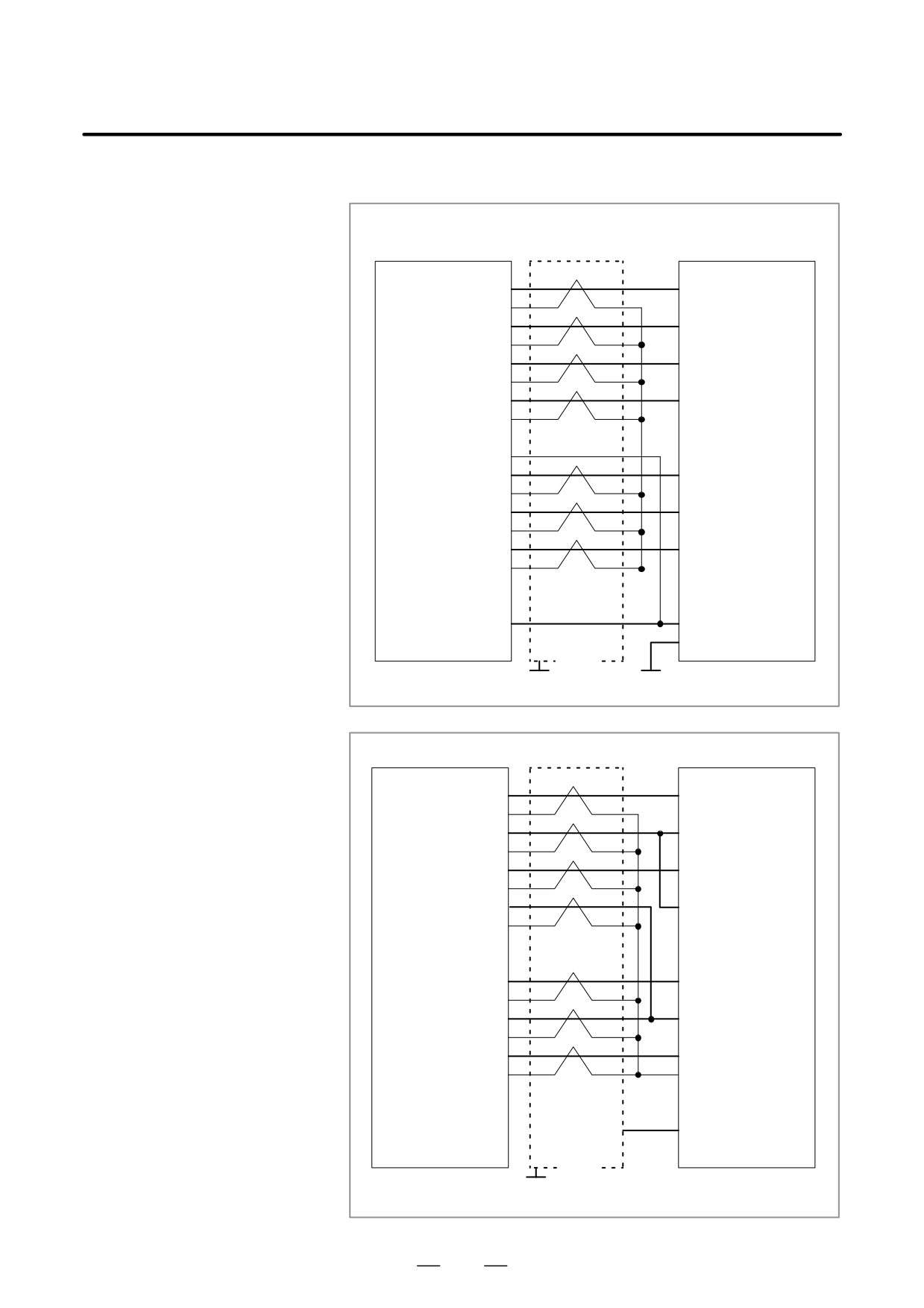
<Connection>
Mother board
R232C(JD36A)
Punch panel
R232C(JD36B)
Tape reader
Serial
R232C(JD28A/JD5L)
communication
Host computer
R232C(JD6A/JD6L)
Host computer
762
B-63525EN/02
11.TROUBLESHOOTING
< Cable connection>
R232C
(JD36A)
(JD36B)
Punch panel
(JD5L)
RD
(01)
(03) RD
0V
(02)
DR
(03)
(06) DR
0V
(04)
CS
(05)
(05) CS
0V
(06)
CD
(07)
(08) CD
0V
(08)
(09)
+24V (10)
SD
(11)
(02) SD
0V
(12)
ER
(13)
(20) ER
0V
(14)
RS
(15)
(04) RS
0V
(16)
(07) SG
(17)
(18)
+24V (19)
(25) +24V
(20)
(01) FG
Shield
G
G
Connector :DBM-25S
Connector : Half-pitch 20-pins (PCR)
R232C
(JD28A)
Host computer
RD
(01)
(02) SD
0V
(02)
DR
(03)
(20) ER
0V
(04)
CS
(05)
(04) RS
0V
(06)
CD
(07)
(08) CD
0V
(08)
(09)
+24V (10)
SD
(11)
(03) RD
0V
(12)
ER
(13)
(06) DR
0V
(14)
RS
(15)
(05) CS
0V
(16)
(07) SG
(17)
(18)
+24V (19)
(25) +24V
(20)
(01) FG
Shield
G
Connector D-SUB 25 pins
Connector : Half-pitch 20-pins (PCR)
763
11. TROUBLESHOOTING
B-63525EN/02
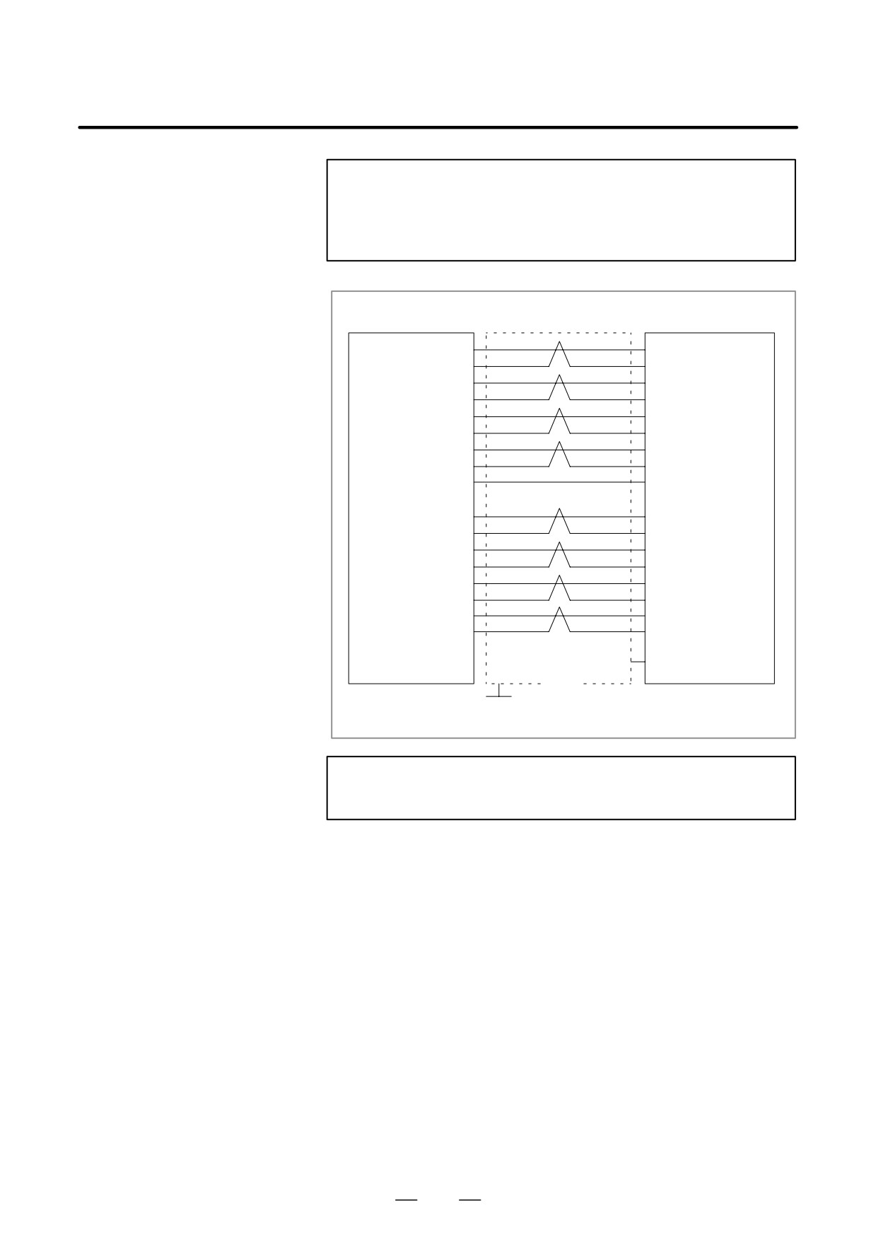
CAUTION
1
When CS is not used, connect it to RS.
2
For protocol A or extended protocol A: When DR is not used,
connect it to ER. Always connect CD to ER.
RS422
(JD6A)
(JD6L)
Host computer
RD (01)
(04) RD
*RD (02)
(22) *RD
RT (03)
(17) TT
*RT (04)
(35) *TT
CS (05)
(07) RS
*CS (06)
(25) *RS
DM (07)
(12)
TR
Note) *DM (09)
(30) *TR
0V (08)
(19) SG
(+24V) (10)
SD (11)
(06) RD
*SD (12)
(24) *RD
TT (13)
(08) RT
*TT (14)
(26) *RT
RS (15)
(09) CS
*RS (16)
(27) *CS
TR (17)
(11) DM
*TR (18)
(29) *DM
(+24V) (19)
(20)
(01) FG
Shield
G
Connector : Half-pitch 20 pins (PCR)
Connector : D-SUB 25 pins
CAUTION
Always use a twisted pair cable.
764
B-63525EN/02
11.TROUBLESHOOTING
11.13
ALARM 90
(REFERENCE
POSITION RETURN
IS ABNORMAL)
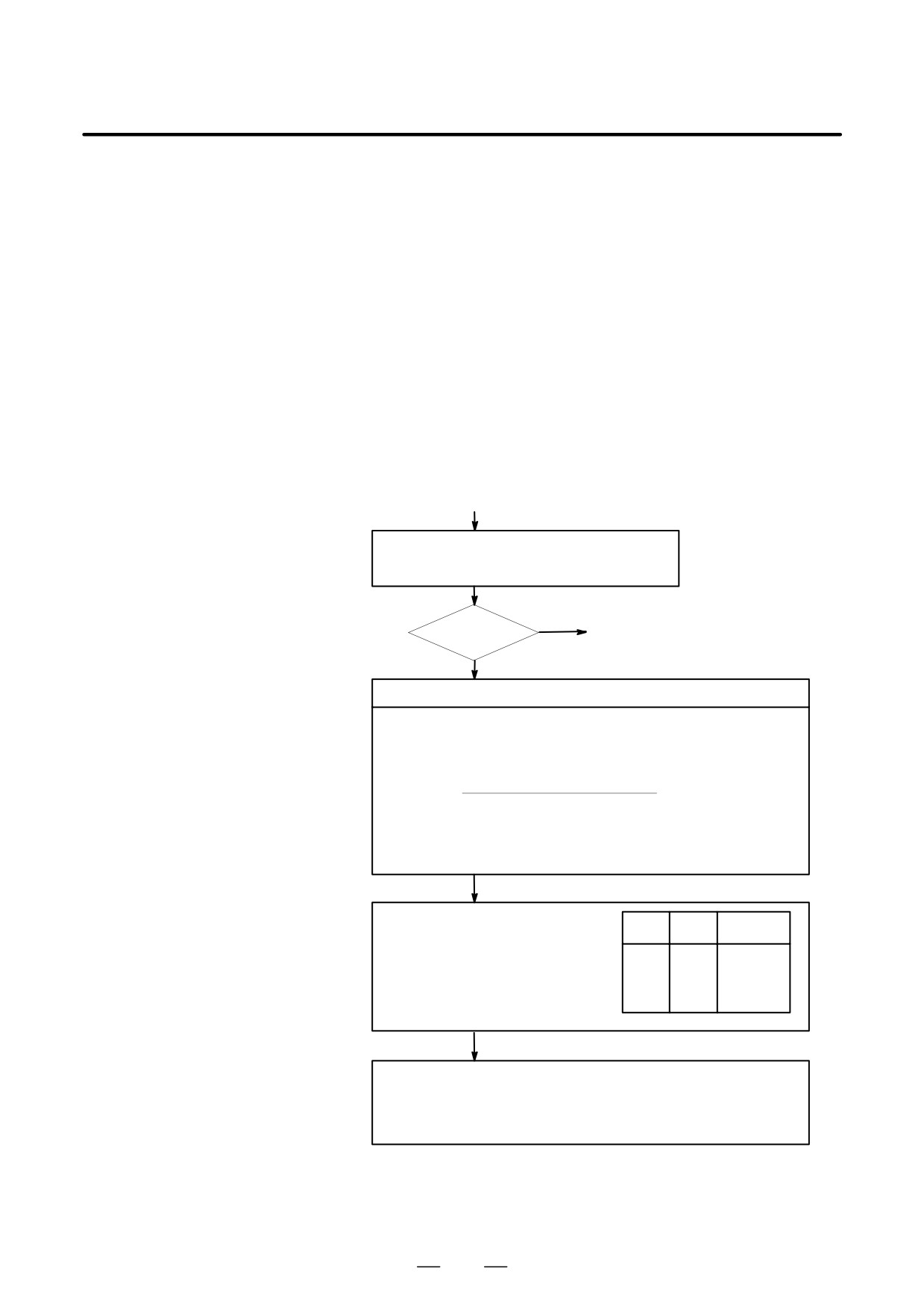
Contents
Reference position return was executed when the following condition is
not satisfied:
The CNC received one rotation signal at least one time when the axis is
moving to the reference position at a speed higher than a speed equivalent
to 128 pulses of position error amount(DGN300).
Countermeasures
(START)
Position error
Check whether position gain is greater than 128 pulses
amount : DGN 300
(DGN 300) before or during reference position return.
YES
128 or more
(1) Next page
NO
Raise the speed
Check feed rate command:
PRM 1420 F : Rapid traverse rate
(mm/min)
PRM 1424
Manual rapid traverse rate (mm/min)
PRM 1825 G : Servo loop gain
(0.01sec-1)
F
5000/3
Position error=
G detection unit[µm/PLUSE]
Detection unit : Move amount to a command pulse (usually 1µm)
In metric machine, if the no. of digits below decimal point is 4 on the position
display screen, detection unit is 0.1 µm.
Check rapid traverse override signals :
ROV1
DGN
014.0
ROV1
ROV2
Override
1014.0 (For two-
path control)
0
0
100%
ROV2
DGN
014.1
0
1
50%
1014.1 (For two-
1
0
25%
path control)
1
1
Fo rate
PRM
1421
Fo rate
Check reference position return deceleration signal
DEC1 to DEC8 DGN 009.0 to 009.7
When reference position return is started from deceleration signal 0, feed rate
becomes FL rate.
PRM 1425 FL rate
765
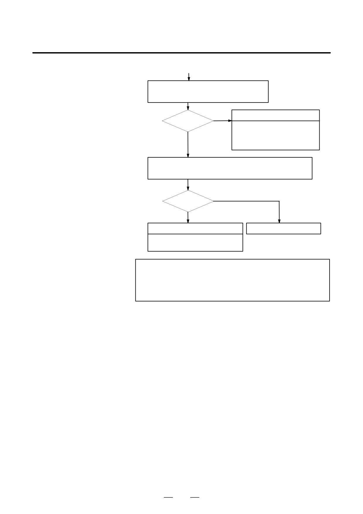
11. TROUBLESHOOTING
B-63525EN/02
(1)
Check whether the motor ratated more than one rota-
tion (one rotation signal is issued ) at faster than 128
pulses of position error amount.
NO
Return start position is too close
Rotated ?
· Chagne the return start position.
· Move the machine at faster that 128
YES
pulses for more than one rotation to
wards RP.
Check that voltage of pulse coder is higher than 4.75 V.
To measure pulse coder voltage, remove the motor cover and measure on
pulse coder PCB at across + and - or +5V and 0V terminals.
NO
More than 4.75V
YES
Hardware failure
Pulse coder power voltage is low
· Pulse coder is faulty
Change pulse coder or motor
CAUTION
After the pulse coder or motor is exchanged, reference
position or machine’s standard point may be different from
former one. Please set it correctly.
D Reference
A speed more than 128 pulses is required because if speed is lower that
this, one-rotation signal does not function stably, causing improper
position detection.
If bit 0 of parameter No. 2000 is set to 1, a speed corresponding to a
positional deviation of 1280 pulses or more is required.
Parameter No. 1836 can be set to 128 or less, as the minimum positional
deviation with which reference position return is possible.
(If the
parameter is set to 0, 128 is assumed as the minimum positional deviation.
If bit 0 of parameter No. 2000 is set to 1, a value equal to ten times the
set value is used for checking.)
766
B-63525EN/02
11.TROUBLESHOOTING
Absolute position data in the serial pulse coder was lost.
11.14
(This alarm will be generated when serial pulse coder is exchanged or
ALARM 300
position feedback signal cable of the serial pulse coder is disconnected).
(REQUEST FOR
REFERENCE
POSITION RETURN)
Remedies
Machine position must be memorized using the following method:
D When reference position
(1) Execute manual reference position return only for an axis for which
return function is
this alarm was generated.When manual reference position return
present
cannot be executed because of an another alarm, set parameter 1815#5
to 0 and release the alarm and perform manual operation.
(2) Press
RESET
key at the end of reference position return to release the
alarm.
D When reference position
Execute dogless reference position setting to memorize the reference
return function is not
position.
present
D When serial pulse coder
Since the reference position is different from the former one, change the
is changed
grid shift value (PRM 1850) to correct the position.
Related parameters
#7
#6
#5
#4
#3
#2
#1
#0
1815
APC x
APZx
#5(APCx)
0 : Position detector is incremental pulse coder.
1 : Position detector is absolute pulse coder.
#4(APZx)
Reference position of absolute pulse coder is :
0 : not established
1 : established
767
11. TROUBLESHOOTING
B-63525EN/02
11.15
ALARM 401
(V READY OFF)
Causes and actions
This alarm is issued if the servo ready signal (VRDY) of a servo amplifier
does not turn on or if the signal turns off during operation.
There are cases in which this alarm is issued because another servo alarm
is issued. If this occurs, first take the action for the first alarm.
Check the power magnetic circuit around the amplifier. The servo
amplifier or the axis control cards on the CNC may be defective.
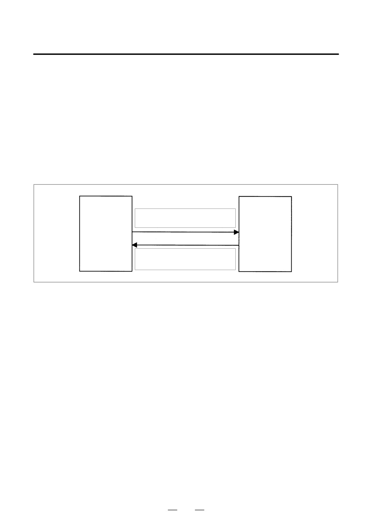
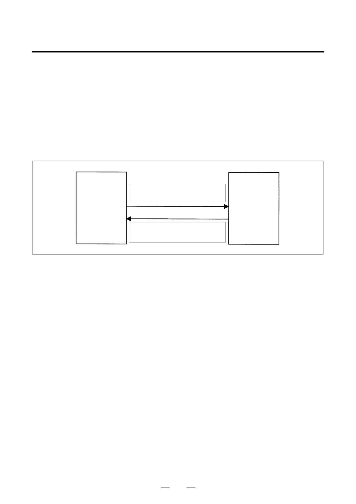
D VRDY
CNC
Servo amplifier
(main CPU board)
MCON: From the CNC to the servo amplifier
(sub-CPU board)
(Turn MCC on to request the activation of the
servo motor)
VRDY: From the servo amplifier to
the CNC
(Notifies that the servo is ready)
The exchange of this information is performed via the FSSB (optical
cable).
768
B-63525EN/02
11.TROUBLESHOOTING
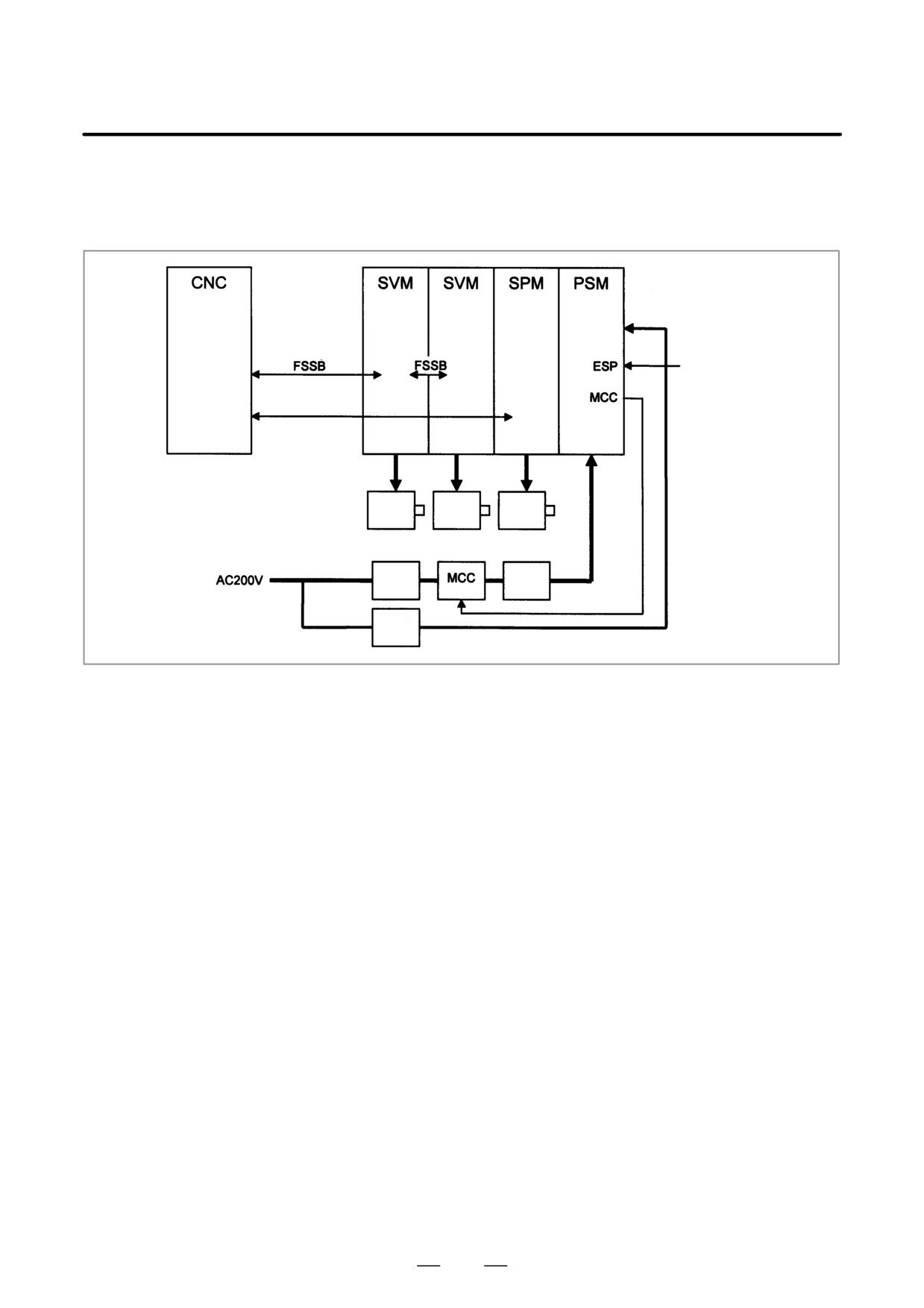
D Example of connection
around the amplifier
(Typical example)
(servo
(servo
amplifier) amplifier)
Control
power
supply
Emergency stop
circuit
Serial spindle
Servo
Servo
Spindle
motor
motor
motor
3-phase
AC
Breaker
reactor
Single-
phase
Breaker
Check items
D Is the PSM control power supply on?
D Has an emergency stop been canceled?
D Is a terminating connector connected to the JX1B connector of the
terminating amplifier?
D Is MCC on? If there is an external MCC sequence in addition to the
MCC contact of the PSM, check that sequence also.
D Is the power for driving MCC supplied?
D Is the breaker on?
D Has some alarm been issued in the PSM or SPM?
D Replacing the servo
If no problem is found in the power magnetic circuit around the amplifier,
amplifier
replace the servo amplifier.
D Replacing the axis
If the above action does not solve the problem, replace the axis control
control cards
cards.
769
11. TROUBLESHOOTING
B-63525EN/02
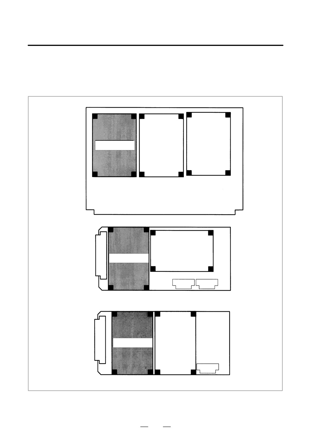
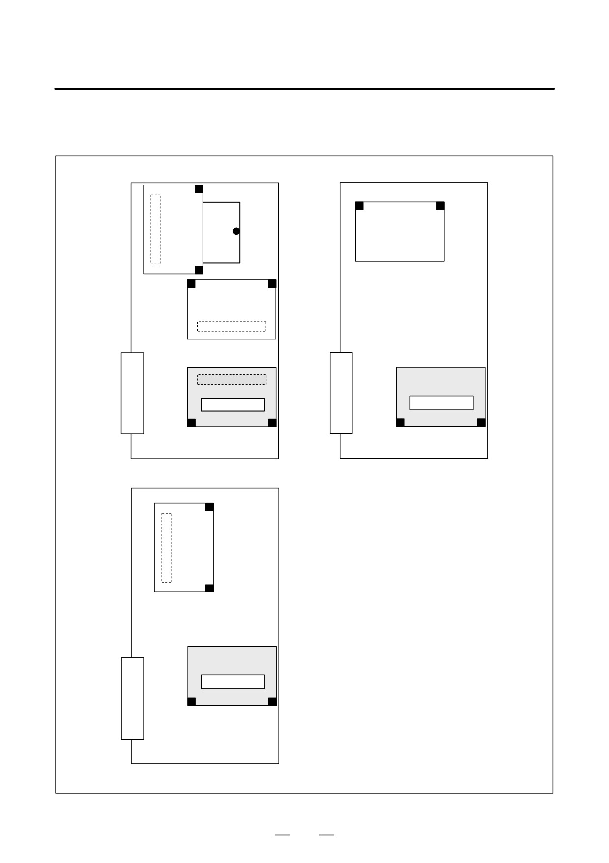
D Installation positions of
the axis control cards
[For the LCD-mounted type]
Axis control card
Motherboard
Axis control card
Sub-CPU board
Axis control card
Loader control board
770
B-63525EN/02
11.TROUBLESHOOTING
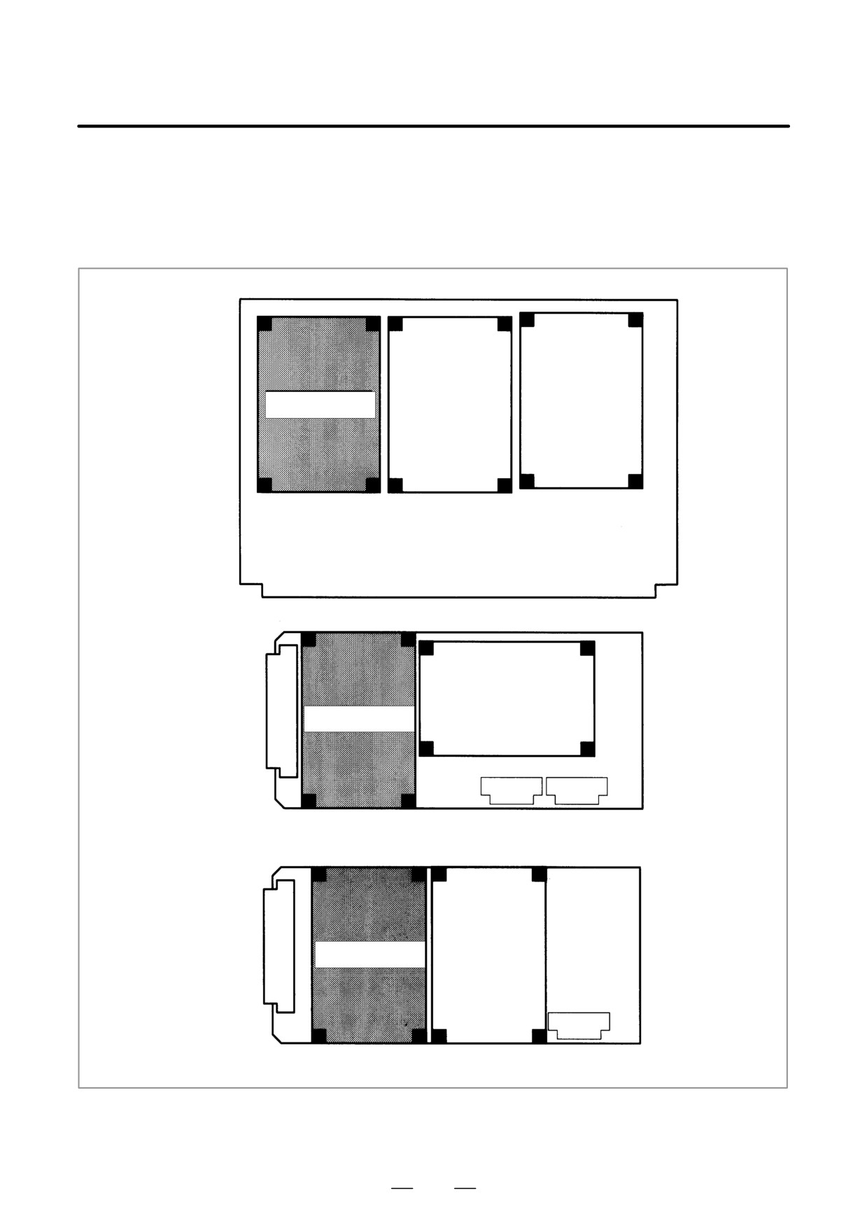
[For the stand-alone
type]
Axis control card
Axis control card
Main CPU board
Sub CPU board
Axis control card
Loarder control board
771
11. TROUBLESHOOTING
B-63525EN/02
11.16
ALARM 404
(V READY ON)
Causes and actions
This alarm is issued if the servo ready signal (VRDY) of a servo amplifier
remains on.
The servo amplifier or the axis control cards on the CNC may be
defective.
D VRDY
CNC
Servo amplifier
(main CPU board)
MCON: From the CNC to the servo amplifier
(sub-CPU board)
(Turn MCC on to request the activation of the
servo motor)
VRDY: From the servo amplifier to
the CNC
(Notifies that the servo is ready)
The exchange of this information is performed via the FSSB (optical
cable).
This alarm is issued if VRDY remains on when the CNC turns MCON
off or if VRDY turns on before the CNC turns MCON on.
D Replacing the servo
The servo amplifier may be defective. Replace the servo amplifier.
amplifier
D Replacing the axis
If replacing the servo amplifier does not solve the problem, replace the
control cards
axis control cards.
772
B-63525EN/02
11.TROUBLESHOOTING
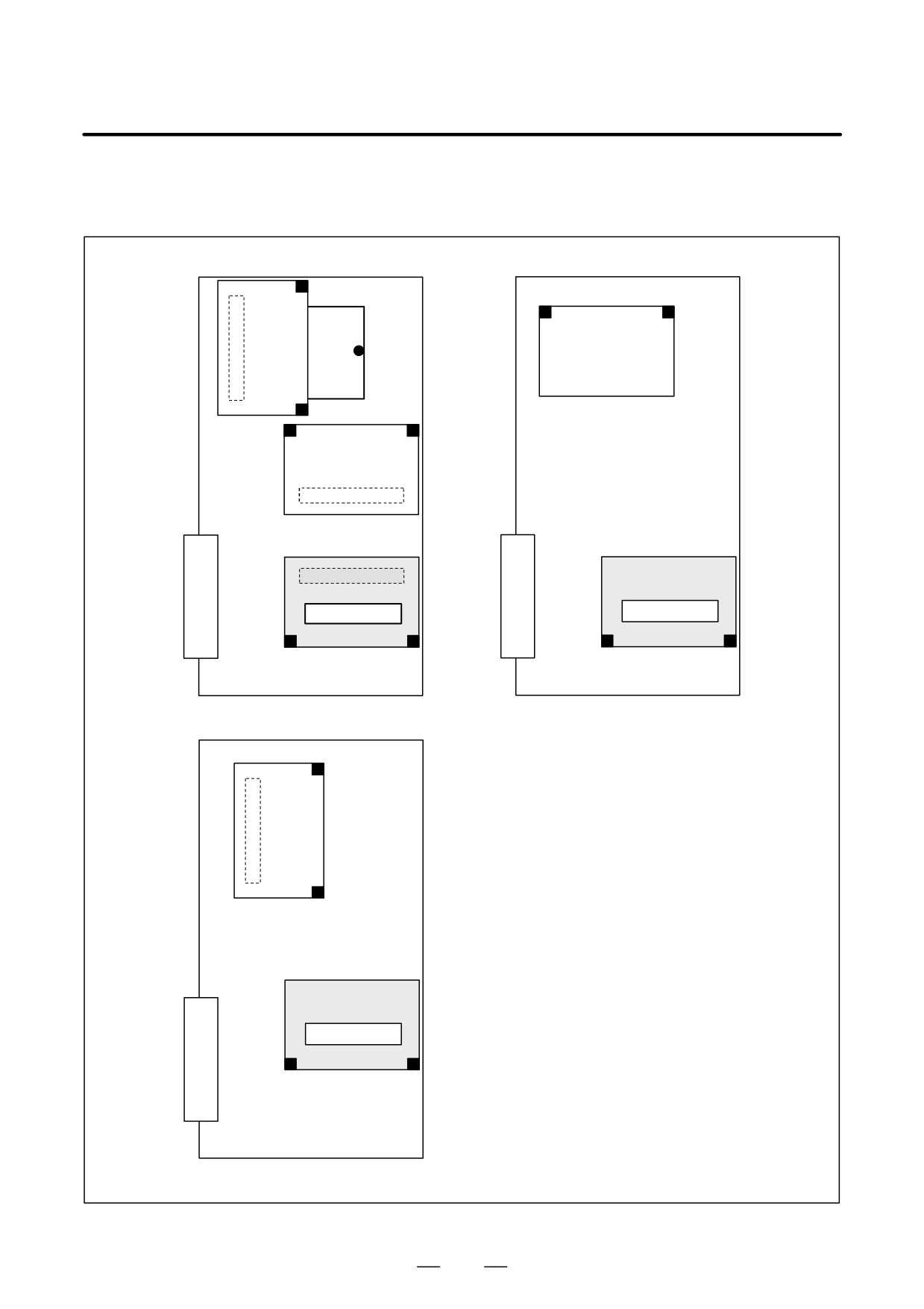
D Installation positions of
the axis control cards
[For the LCD-mounted type]
Axis control card
Motherboard
Axis control card
Sub-CPU board
Axis control card
Loader control board
773
11. TROUBLESHOOTING
B-63525EN/02
[For the stand-alone
type]
Axis control card
Axis control card
Main CPU board
Sub CPU board
Axis control card
Loarder control board
774
B-63525EN/02
11.TROUBLESHOOTING
11.17
ALARM 462
(SEND CNC DATA
FAILED)
ALARM 463
(SEND SLAVE DATA
FAILED)
Causes and actions
Alarm 462 is issued if a slave (servo amplifier) cannot receive correct data
due to an FSSB communication error.
Alarm 463 is issued if the CNC cannot receive correct data due to an FSSB
communication error.
If these alarms are issued, the alarm message indicates the number of the
defective axis (axis name).
D Servo amplifier or optical
Any of the optical cables between the CNC control unit and the amplifier
cable
corresponding to the axis number indicated in the alarm message may be
defective.
Or, any of the first amplifier to the amplifier corresponding to that axis
number may be defective.
D Axis control cards
The axis control cards installed on the CNC may be defective.
775
11. TROUBLESHOOTING
B-63525EN/02
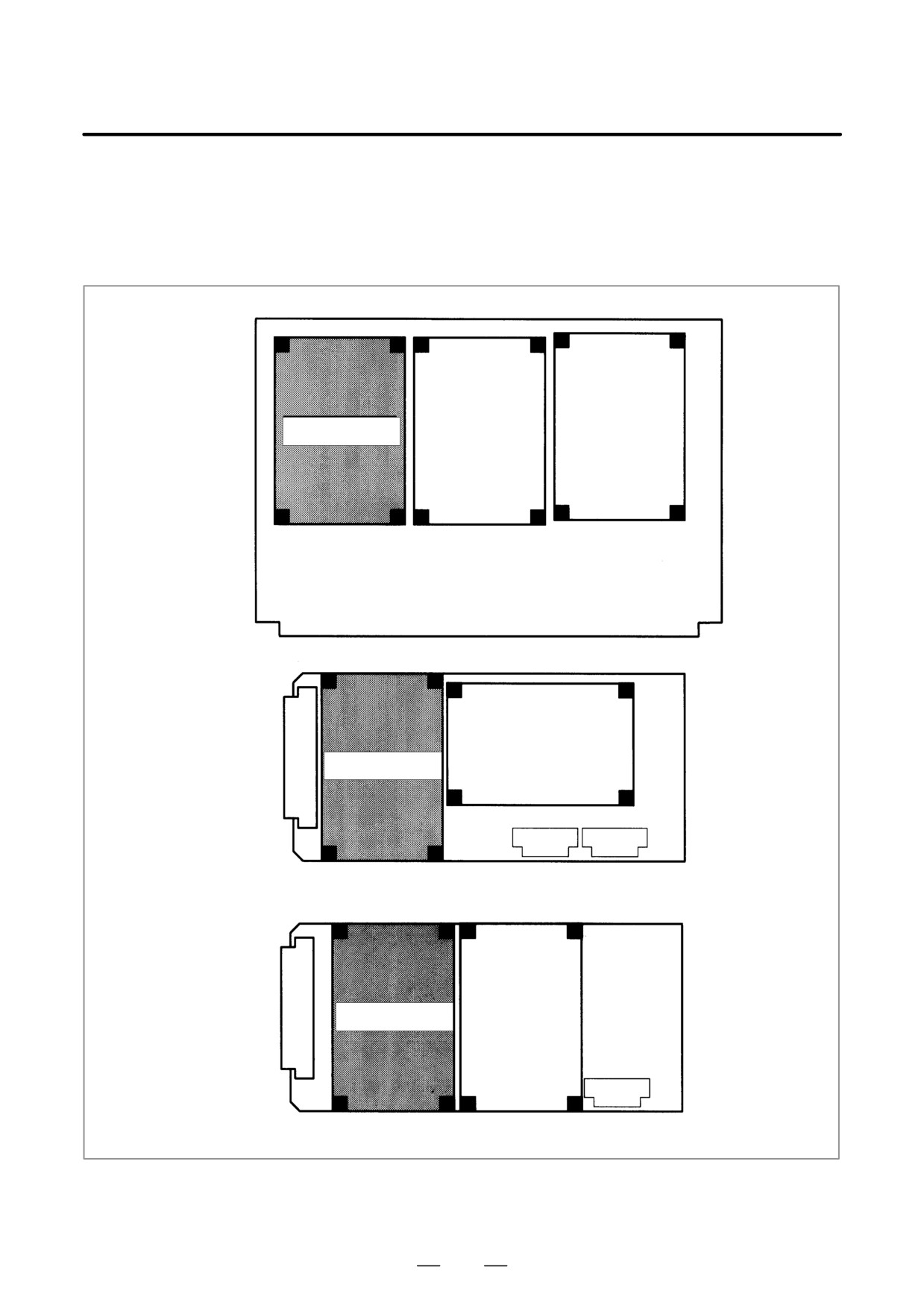
D Installation positions of
the axis control cards
[For the LCD-mounted type]
Axis control card
Motherboard
Axis control card
Sub-CPU board
Axis control card
Loader control board
776
B-63525EN/02
11.TROUBLESHOOTING
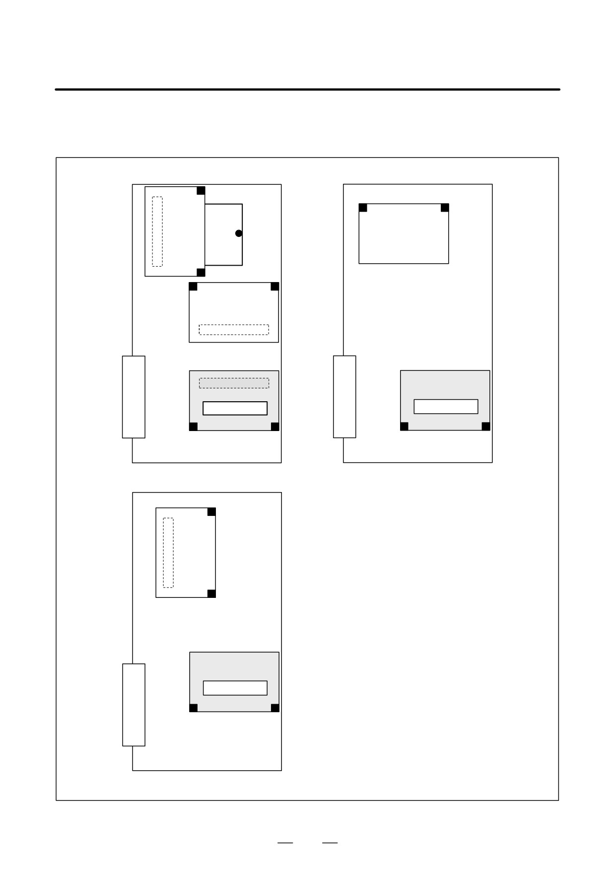
[For the stand-alone
type]
Axis control card
Axis control card
Main CPU board
Sub CPU board
Axis control card
Loarder control board
777
11. TROUBLESHOOTING
B-63525EN/02
Digital servo parameters are abnormal.
11.18
(Digital servo parameters are set incorrectly.)
ALARM 417 (DIGITAL
SERVO SYSTEM IS
ABNORMAL)
D Causes
1
Confirm the setting value of the following parameters:
PRM 2020 : Motor format number
PRM 2022 : Motor rotation direction
PRM 2023 : Number of pulses of velocity feedbacks
PRM 2024 : Number of pulses of position feedback
PRM 1023 : Servo axis number
PRM 2084 : Flexible feed gear ratio
PRM 2085 : Flexible feed gear ratio
Confirm the details with diagnosis function of CNC side.
2
Change the setting of this parameter to 0.
PRM 2047 : Observer parameter
3
Perform initial setting of digital servo parameters.
Refer to setcion 6.1 “Initial Setting of Servo Parameters” .
This data indicates the cause of servo alarm No. 417, detected by the NC.
If the alarm is detected by the servo, the PRM bit (bit 4 of DGN No. 0203)
is set to 1.
#7
#6
#5
#4
#3
#2
#1
#0
0280
AXS
DIR
PLS
PLC
MOT
#0(MOT) :
The motor type specified in parameter No. 2020 falls outside the
predetermined range.
#2(PLC) :
The number of velocity feedback pulses per motor revolution, specified in
parameter No. 2023, is zero or less. The value is invalid.
#3(PLS) :
The number of position feedback pulses per motor revolution, specified in
parameter No. 2024, is zero or less. The value is invalid.
#4(DIR) :
The wrong direction of rotation for the motor is specified in parameter No.
2022 (the value is other than 111 or -111).
#6(AXS) :
In parameter No. 1023 (servo axis number), a value that falls outside the
range of 1 to the number of controlled axes is specified. (For example, 4 is
specified instead of
3.)
Alternatively, the values specified in the
parameter are not consecutive.
778
B-63525EN/02
11.TROUBLESHOOTING
11.19
ALARM 700
(OVERHEAT:
CONTROL UNIT)
Causes and actions
This alarm is issued if the ambient temperature of the CNC control unit
is abnormally high. As an installation condition, the ambient temperature
of the CNC must not exceed 58°C (for LCD-mounted type CNC) or 55°C
(for stand-alone type CNC).
D Ambient temperature
A temperature monitoring circuit is installed on the motherboard (main
CPU board), and causes this alarm to be issued if the ambient temperature
is abnormally high.
Take appropriate action to the cabinet that houses the CNC control unit
so that the temperature falls within the proper temperature range (0 to
58°C (for LCD-mounted type CNC) or 0 to 55°C (for stand-alone type
CNC).
If it is obvious that the ambient temperature is not abnormal, the
motherboard (main CPU board) may be defective.
779
11. TROUBLESHOOTING
B-63525EN/02
11.20
ALARM 701
(OVERHEAT: FAN
MOTOR)
Causes and actions
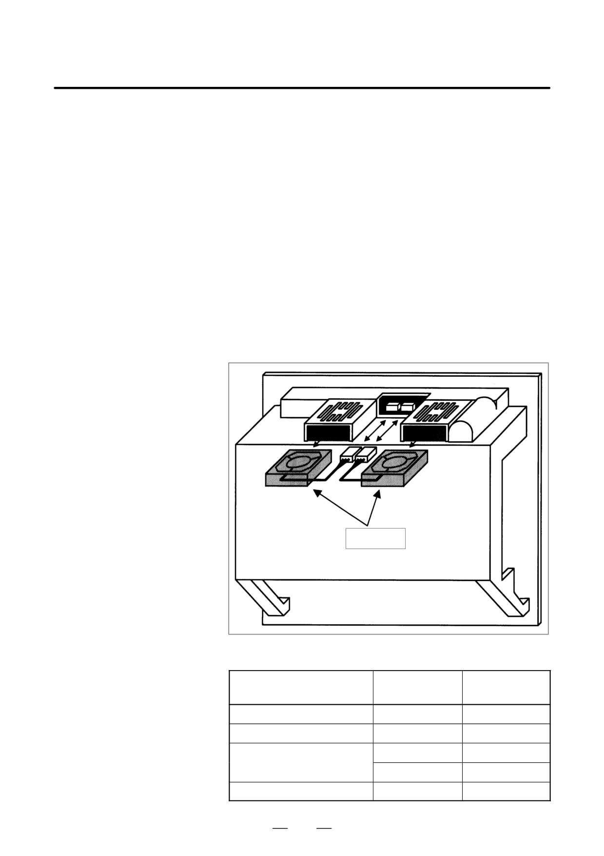
This alarm is issued if a fault occurs in any of the fan motors, such as the
stoppage of a fan motor during the operation of the CNC.
D Fan motors
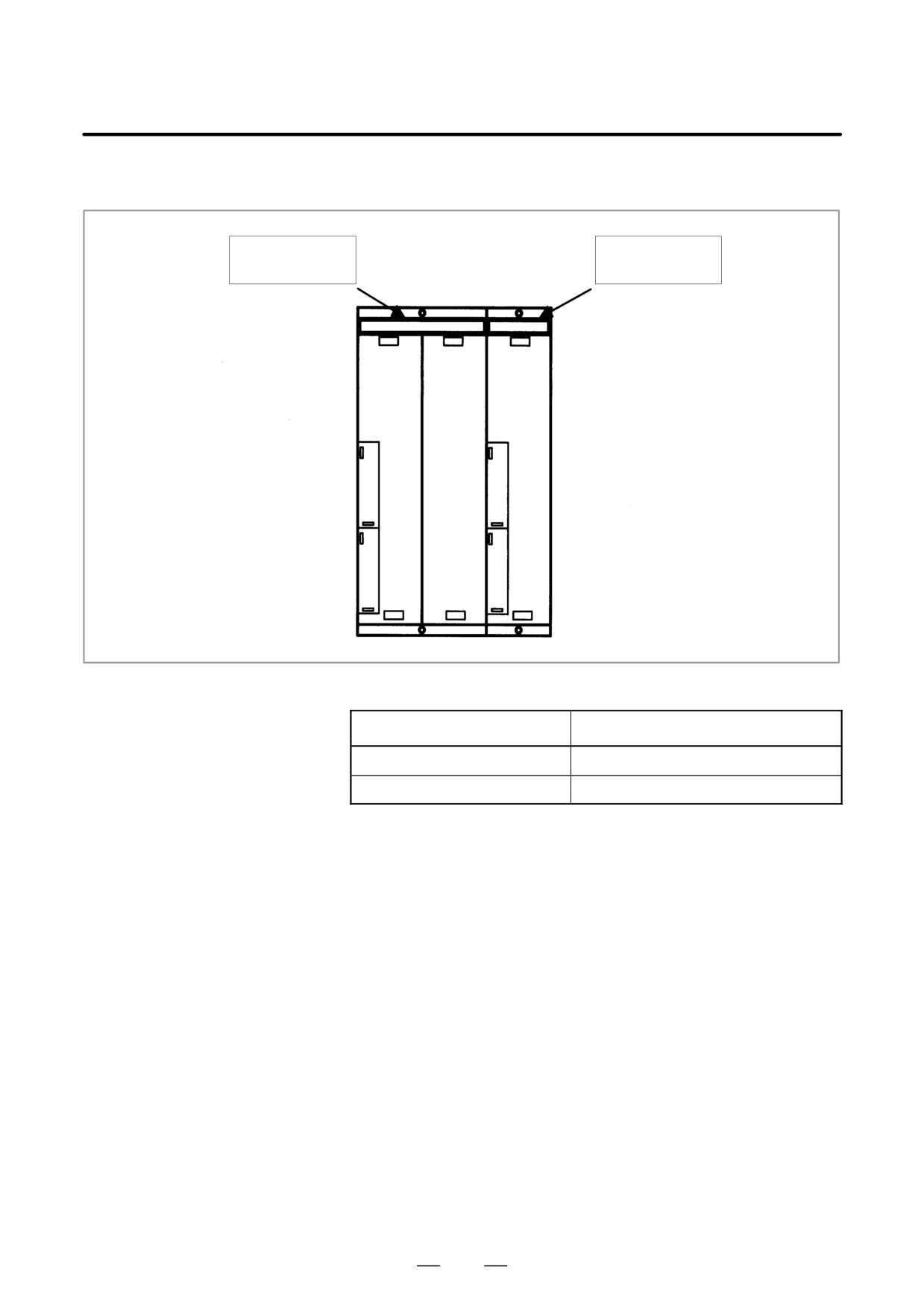
Fan motors are installed in the uppermost portion of the CNC control unit.
Each fan motor is attached with an alarm detector circuit, which notifies
the CNC of a fault such as the stoppage of the fan motor, thereby issuing
this alarm.
If this alarm is issued, replace the fan motor.
[For the LCD-mounted type]
For units without option slots
Fan motor
Specifications of fan motors
Ordering
Quantity
information
required
Unit without option slots
A02B-0236-K120
Two
Unit with two option slots
A02B-0281-K121
Two
Unit with three option slots
A02B-0281-K121
Two
A02B-0236-K122
Two
Unit with four option slots
A02B-0281-K121
Four
780
B-63525EN/02
11.TROUBLESHOOTING
[For the stand-alone type]
For the stand-alone type, a fan can be replaced together with its case.
Fan motor for
Fan motor for
2-slot track
1-slot track
Specifications of fan motors
Ordering information
For 1-slot track
A02B-0265-C101
For 2-slot track
A02B-0260-C021
781