FANUC Series 16i/160i/160is-MODEL B, Series 18i/180i/180is-MODEL B, Series 21i/210i/210is-MODEL B. MAINTENANCE MANAUL - page 28
11. TROUBLESHOOTING
B-63525EN/02
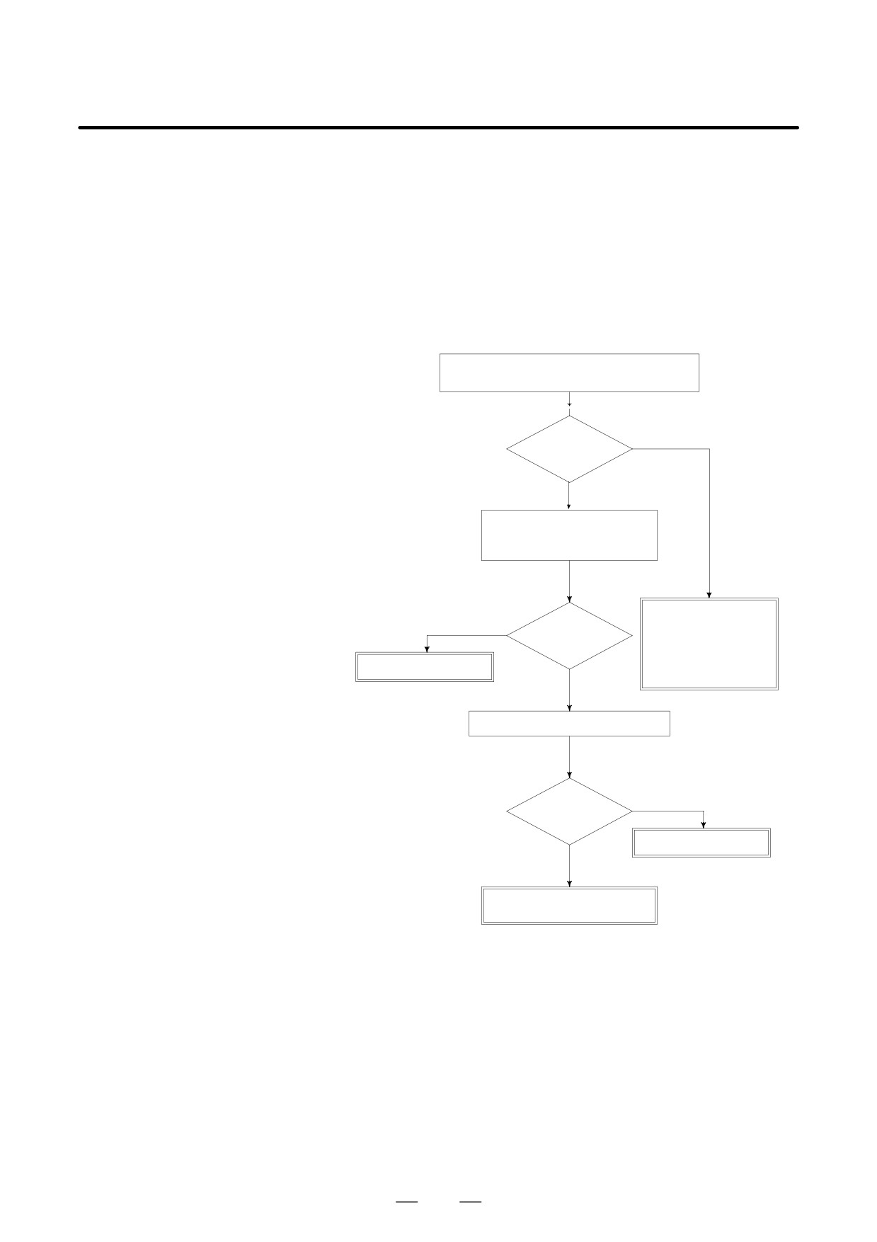
Spindle speed changes abnormally due to load.
11.21
ALARM 704
(SPINDLE SPEED
FLUCTUATION
DETECTION ALARM)
Remedies
Check whether spindle speed is constant by view
of the speed meter on CRT.
YES
Constant ?
NO
Is a heavy cutting being per-
formed ? Confirm spindle load
on CRT.
Confirm the follow-
ing parameter :
YES
Heavy cutting?
PRM 4911
PRM 4912
Reduce cutting condition
PRM 4913
NO
PRM 4914
Doesn’t the cutting tool worn ?
YES
Worn ?
Replace tool
NO
Spindle servo unit is faulty
Spindle motor is faulty
Remedies
PRM 4911 : A ratio of spindle speed at which actual spindle speed is
regarded as arrived at a command spindle speed.
PRM 4912 : Spindle speed fluctuation ratio up to which the spindle
speed fluctuation detection alarm is not issued.
PRM 4913 : Spindle speed fluctuation that is not regarded as the spindle
speed fluctuation alarm.
PRM 4914 : Time when a spindle speed changed to when spindle speed
fluctuation detection is started.
782
B-63525EN/02
11.TROUBLESHOOTING
11.22
ALARM 749
(SERIAL SPINDLE
COMMUNICATION
ERROR)
Causes and actions
An error occurred in the communication between the serial spindle
amplifier (SPM) and the CNC. The probable causes include:
D Contact failure of the connection cable
D Defective printed circuit board on the CNC
D Defective spindle amplifier
D Noise
D Connection cable
Check that the cable connecting the serial spindle amplifier (SPM) to the
CNC is in contact.
Check that the cable is inserted firmly into the connectors and that it does
not have any conductors likely to be cut off.
Check that the cable used is a twisted-pair cable and that it is connected
as described in the connection manual.
D Printed circuit boards on
A spindle control circuit for the CNC is installed on the motherboard and
the CNC
the sub-CPU board. If this alarm is issued from the main CPU, replace
the motherboard. If it is issued from the sub-CPU, replace the sub-CPU
board.
D Spindle amplifier module
When an error occurred on the spindle amplifier module (SPM) side, a
(SPM)
code of A, A1, or A2 is indicated on the SPM depending on the nature of
the error.
In this case, take appropriate actions in FANUC SERVO MOTOR αi
series Maintenance Manual (B-65285EN) or FANUC SERVO MOTOR
α series Maintenance Manual (B-65165E).
D Noise environment
If any of the above actions does not solve the problem, examine the noise
environment of the connection cable.
See the section on the measures against noise, take appropriate actions
such as the reinforcement of the cable shield and the separation of the
cable from the power line.
783
11. TROUBLESHOOTING
B-63525EN/02
11.23
ALARM 750
(SPINDLE SERIAL
LINK
STARTUP FAILURE)
Causes and actions
This alarm is issued if a serial spindle amplifier (SPM) does not enter the
normal startup state when the CNC is turned on.
This alarm is not issued once the CNC system including the spindle
amplifiers has started up normally. It is issued if a fault occurs in the
power-on process.
The probable causes include the following:
D Contact failure, wiring error, or connection error of the connection
cable
D The CNC is turned on when a spindle amplifier is in the alarm state.
D Parameter setting error
D Defective printed circuit board on the CNC
D Detective spindle amplifier
D Connection
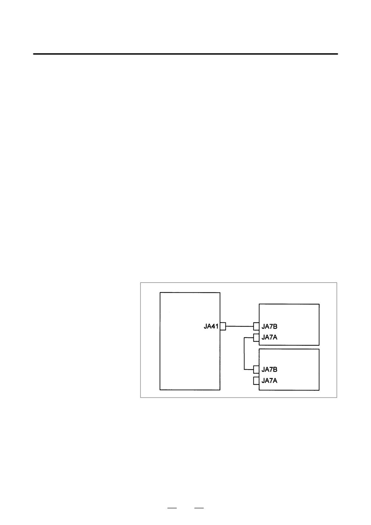
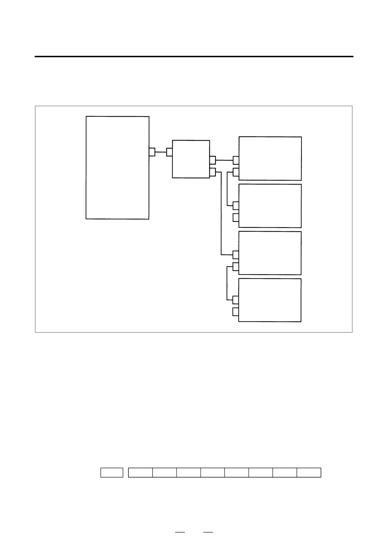
Up to four serial spindle amplifiers (SPMs) can be connected per path.
Note, however, the number of amplifiers that can be connected differs
depending on the model, number of paths, and configuration. Refer to the
Connection Manual (Hardware).
[Diagram of connection of
up to two amplifiers per
path]
Motherboard
(Main CPU board)
Sub-CPU board
SPM (first)
SPM (second)
784
B-63525EN/02
11.TROUBLESHOOTING
[Diagram of connection of
three or four amplifiers per
path]
Motherboard
(Main CPU board)
Sub-CPU board
Connector panel
SPM (first)
JA41
JA48
JA7A-1
JA7B
JA7A-2
JA7A
SPM (second)
JA7B
JA7A
SPM (third)
JA7B
JA7A
SPM (fourth)
JA7B
JA7A
Check that the cables are connected as shown in the figure above. Check
that JA7Bs and JA7As are connected correctly.
Check that the cables are latched firmly and are not loose.
Refer to the Connection Manual (Hardware) to check that the cables are
connected correctly.
D States of the spindle
This alarm is issued if the CNC is turned on when the LED of a spindle
amplifiers
amplifier indicates a number other than “24”.
On the spindle amplifier, remove the cause of the alarm. Turn off the
spindle amplifier and the CNC, then turn on the system again.
D Details of the alarm
If this alarm is issued, its details can be checked with diagnosis numbers
409 and 439.
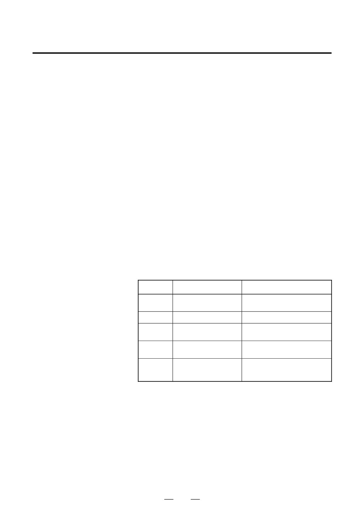
D 1st and 2nd spindles
#7
#6
#5
#4
#3
#2
#1
#0
0409
SPE
S2E
S1E
SHE
SPE:
0 : In the spindle serial control, the serial spindle parameters fulfill the
spindle unit startup conditions.
1 : In the spindle serial control, the serial spindle parameters do not fulfill
the spindle unit startup conditions.
785
11. TROUBLESHOOTING
B-63525EN/02
S2E:
0 : The second spindle is normal during the spindle serial control startup.
1 : The second spindle was detected to have a fault during the spindle
serial control startup.
S1E:
0 : The first spindle is normal during the spindle serial control startup.
1 : The first spindle was detected to have a fault during the spindle axis
serial control startup.
SHE:
0 : The serial communications circuit in the CNC is normal.
1 : The serial communications circuit in the CNC was detected to have a
fault.
D
3rd and 4th spindles
The details of spindle alarm No. 750 are displayed in the diagnosis display
(No. 409) as shown below.
#7
#6
#5
#4
#3
#2
#1
#0
0409
SPE
S4E
S3E
SHE
SPE:
0 :
In the spindle serial control, the serial spindle parameters fulfill the
spindle unit startup conditions.
1 :
In the spindle serial control, the serial spindle parameters do not fulfill
the spindle unit startup conditions.
S4E:
0 :
The fourth spindle is normal during the spindle serial control startup.
1 :
The fourth spindle was detected to have a fault during the spindle
serial control startup.
S3E:
0 :
The third spindle is normal during the spindle serial control startup.
1 :
The third spindle was detected to have a fault during the spindle axis
serial control startup.
SHE:
0 :
The serial communications circuit in the CNC is normal.
1 :
The serial communications circuit in the CNC was detected to have a
fault.
1)
If SPE is set to “1”
Re-check the serial spindle parameters with numbers 4000 to 4999.
2)
If S1E is set to “1”
Because a fault was detected on first spindle, check its connection and
parameter settings.
3)
If S2E is set to “1”
Because a fault was detected on second spindle, check its connection
and parameter settings. This alarm is issued if the parameter settings
are such that second spindle is used although only first spindle is used.
4)
IF S3E is set to ”1”
Because a fault was detected on third spindle, check its connection and
parameter settings.
An alarm also occurs when the setting is made so that the third axis is
intended to be connected even though it is not actually connected.
5)
IF S4E is set to ”1”
Because a fault was detected on fourth spindle, check its connection
and parameter settings.
An alarm also occurs when the setting is made so that the fourth axis
is intended to be connected even though it is not actually connected.
If any of the above actions does not solve the problem, the motherboard,
servo CPU board, or spindle amplifier may be defective.
6) If SHE is set to “1”
Replace the motherboard or sub-CPU board.
786
B-63525EN/02
11.TROUBLESHOOTING
11.24
ALARM 5134
(FSSB: OPEN
READY TIME OUT)
ALARM 5135 (FSSB:
ERROR MODE)
ALARM 5137 (FSSB:
CONFIGURATION
ERROR)
ALARM 5197 (FSSB:
OPEN TIME OUT)
ALARM 5198 (FSSB:
ID DATA NOT READ)
Causes and actions
These alarms are issued if any of the axis control cards and the slaves
(such as servo amplifiers) and optical cables connected to the FSSB is
defective.
No.
Message
Description
5134
FSSB: OPEN READY TIME
The FSSB did not become ready to
OUT
open during initialization.
5135
FSSB: ERROR MODE
The FSSB entered an error mode.
5137
FSSB: CONFIGURATION
The FSSB detected a configuration er-
ERROR
ror.
5197
FSSB: OPEN TIME OUT
The FSSB did not open when the CNC
had allowed the FSSB to open.
5198
FSSB: ID DATA NOT READ
The initial ID information for the amplifi-
er cannot be read because of a failure
in the temporary assignment.
D Processing of the FSSB
The processing of the FSSB at power on is as described below:
at power on
1
The CNC initializes the FSSB and the servo.
2
The servo returns the first ready signal.
3
The first ITP interrupt is generated.
4
The CNC waits for the FSSB to become ready to open.
5
The CNC checks that the FSSB did not detect a configuration error.
6
The CNC allows the FSSB to open.
7
The CNC checks that the FSSB has opened.
8
The servo returns the second ready signal.
9
Normal operation
787
11. TROUBLESHOOTING
B-63525EN/02
If the FSSB does not become ready to open in 4, alarm 5134 is issued.
If an error is detected in 5, alarm 5137 is issued.
If the FSSB does not open within a fixed period of time, alarm 5197 is
issued.
If the ready signal is not returned within a fixed period of time, alarm 5198
is issued.
D Checking the parameter
Check that the FSSB-related parameters are set correctly.
settings
D Power supplies of the
Check the power supplies of the servo amplifiers connected to the FSSB.
servo amplifiers
D Replacing the axis
Replace the axis control cards on the CNC.
control cards, optical
Replace the optical cables and servo amplifiers connected to the FSSB,
cables, and servo
one at a time, to identify the defective item.
amplifiers
788
B-63525EN/02
11.TROUBLESHOOTING
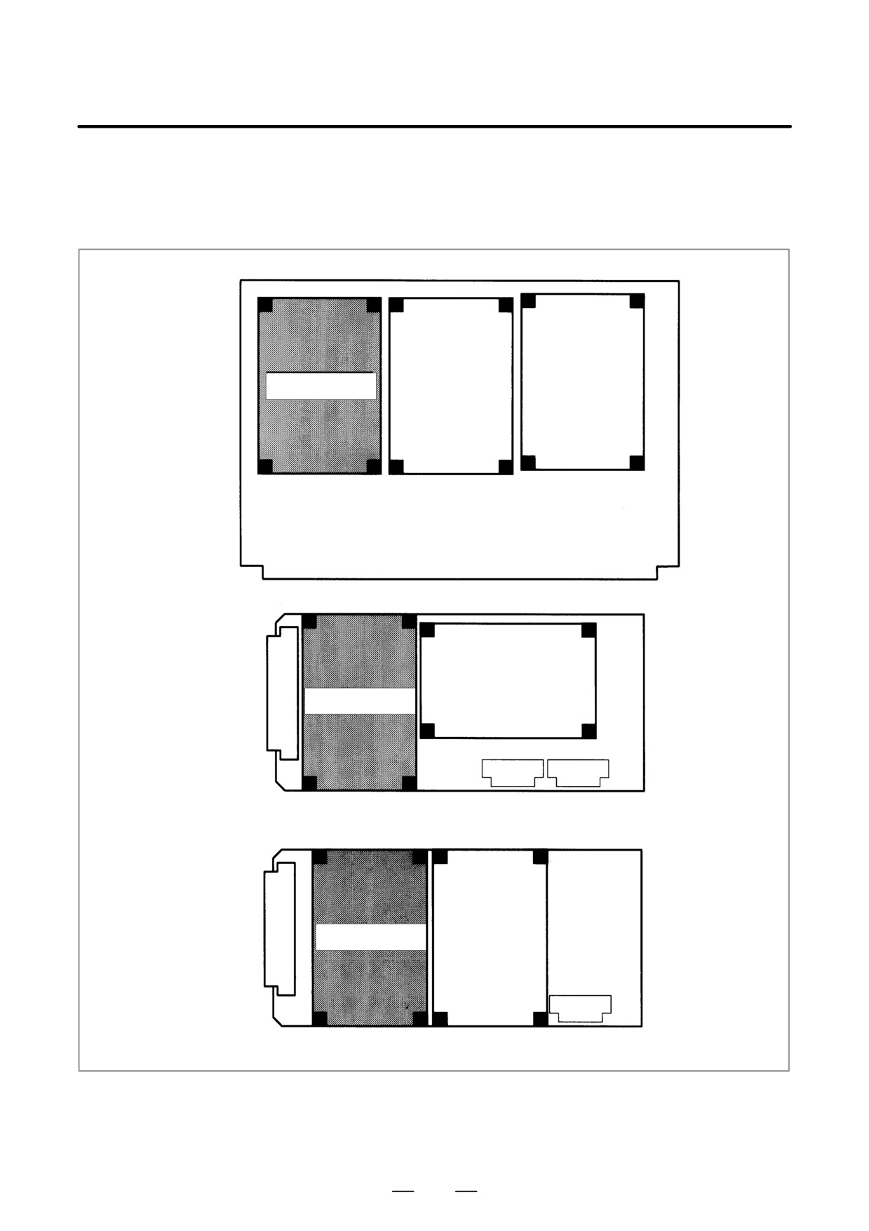
D Installation positions of
the axis control cards
[For the LCD-mounted type]
Axis control card
Motherboard
Axis control card
Sub-CPU board
Axis control card
Loader control board
789
11. TROUBLESHOOTING
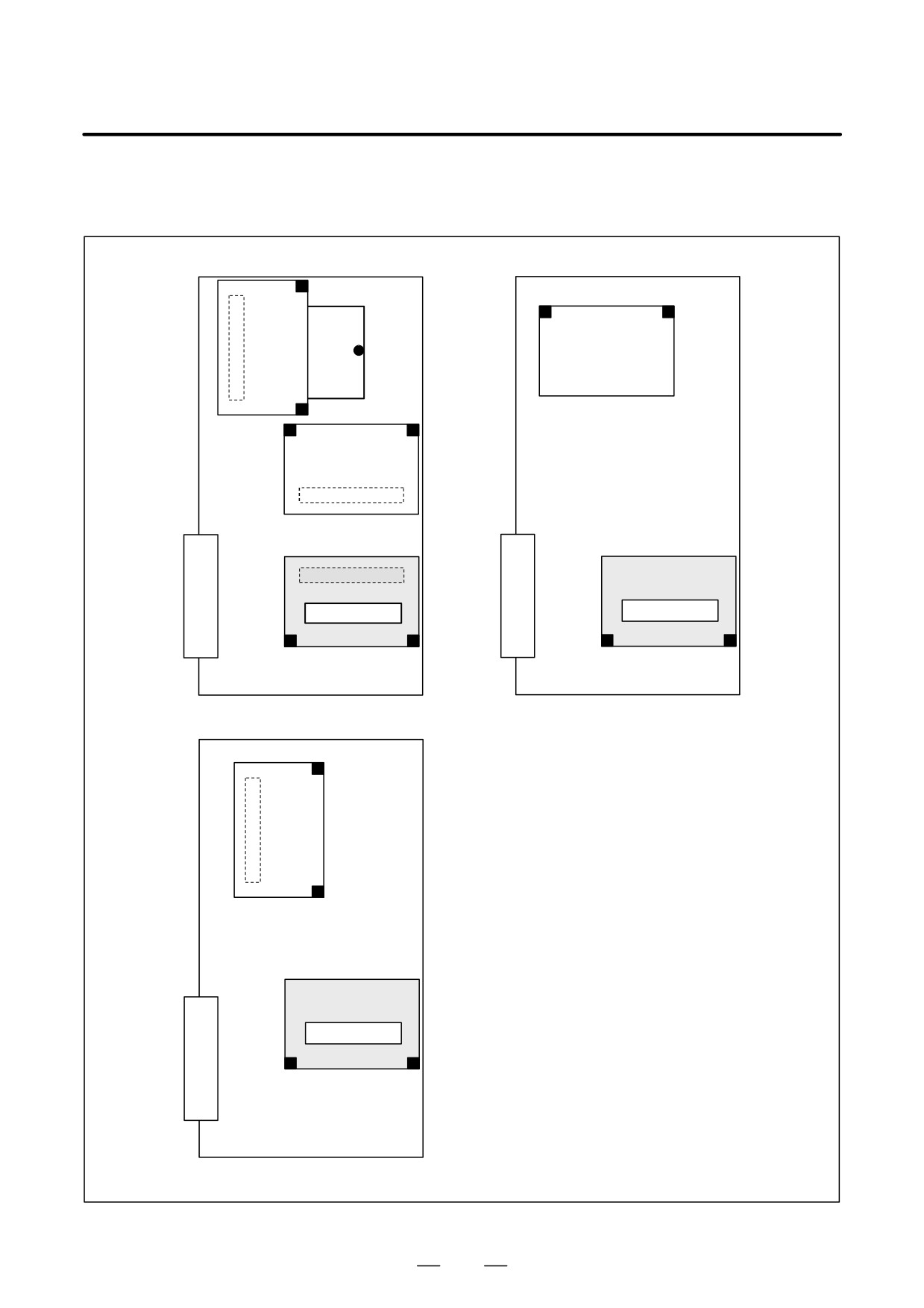
B-63525EN/02
[For the stand-alone
type]
Axis control card
Axis control card
Main CPU board
Sub CPU board
Axis control card
Loarder control board
790
B-63525EN/02
11.TROUBLESHOOTING
11.25
ALARM 5136
(FSSB: NUMBER OF
AMPS IS SMALL)
Causes and actions
The number of servo amplifiers recognized by the FSSB is insufficient,
compared with the number of controlled axes.
D FSSB setting screen
If this alarm is issued, display the amplifier setting screen from the FSSB
setting screen. Only the servo amplifiers recognized on the FSSB are
displayed.
D Optical cable or servo
The optical cable that connects together the last recognized amplifier and
amplifier
the next one may be defective.
Or, either of the amplifiers connected together with that optical cable may
be defective. Check the power supplies of the amplifiers.
D Power fault of a servo
This alarm may be issued if a power fault occurs in a servo amplifier. A
amplifier
power fault occurs if the amplifier control power supply voltage drops,
if the +5 V conductor of the pulse coder cable is ground, or for other
reasons.
D Axis control cards
The axis control cards installed on the CNC may be defective.
791
11. TROUBLESHOOTING
B-63525EN/02
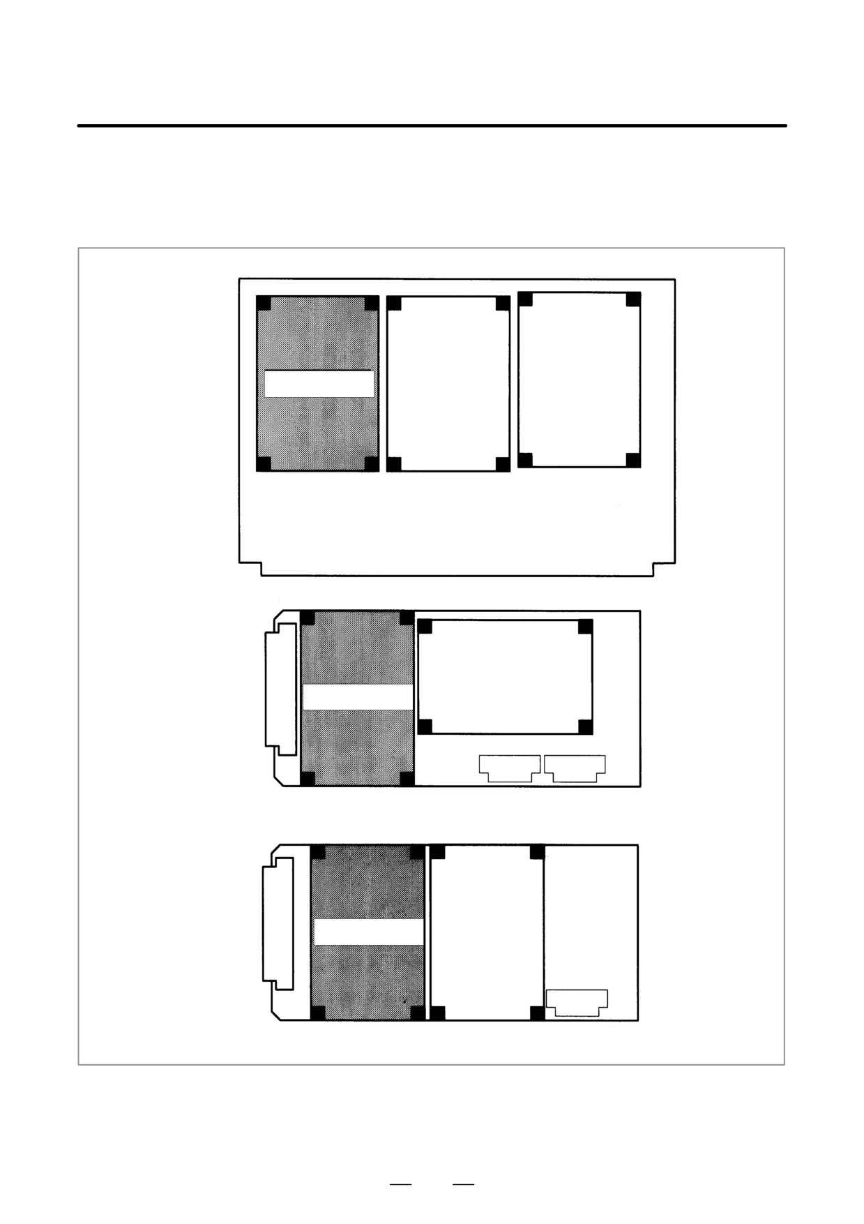
D Installation positions of
the axis control cards
[For the LCD-mounted type]
Axis control card
Motherboard
Axis control card
Sub-CPU board
Axis control card
Loader control board
792
B-63525EN/02
11.TROUBLESHOOTING
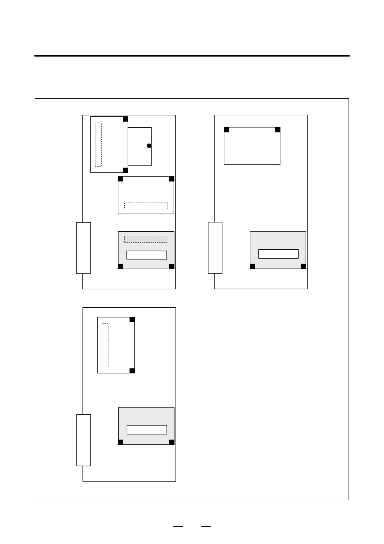
[For the stand-alone
type]
Axis control card
Axis control card
Main CPU board
Sub CPU board
Axis control card
Loarder control board
793
11. TROUBLESHOOTING
B-63525EN/02
11.26
ALARM 900
(ROM PARITY)
Causes and actions
A ROM parity error occurred.
The software including the CNC system software, servo software, PMC
management software, and PMC Ladder is stored in the flash memory on
the FROM/SRAM module. It starts execution after being loaded into the
RAM of the DRAM module or servo card at power on.
A ROM parity error occurs if the software stored in the FROM/SRAM
module is destroyed.
D Rewriting the software
On the screen, the series of the software in which a fault was detected is
component
displayed. Rewrite the software using the boot system.
The software stored in the FROM/SRAM module includes a variety of
FANUC software components, as well as those created by the MTB, such
as the PMC Ladder.
D Replacing the
Replace the FROM/SRAM module
FROM/SRAM module
After replacement, all the software that was once stored must be written.
Because the replacement clears the contents of the SRAM memory, the
memory contents must be restored. For this operation, use the boot
system.
D Replacing the
If any of the above actions does not solve the problem, replace the
motherboard
motherboard.
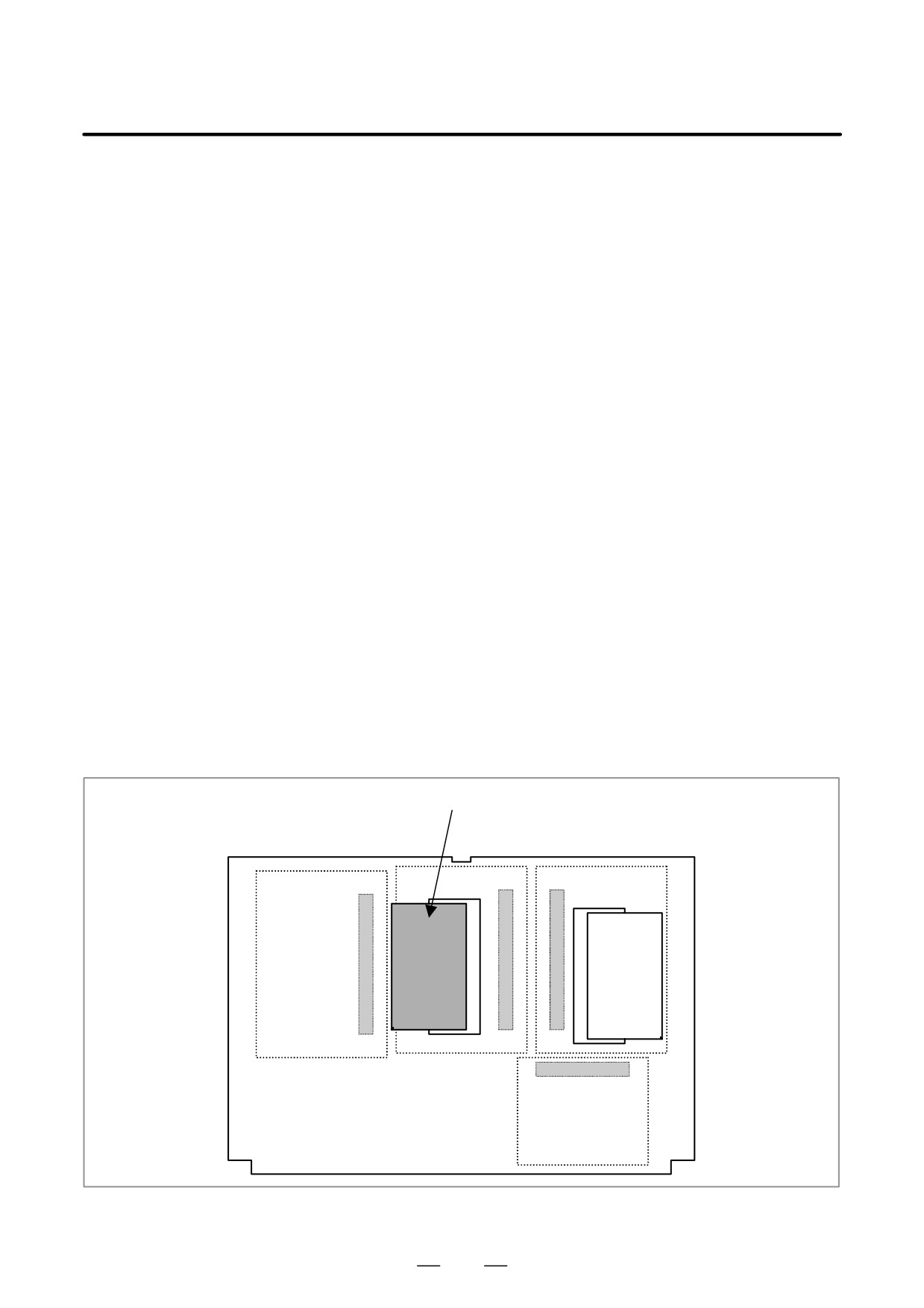
D Installation position of
the FROM/SRAM module
[For the LCD-mounted type]
FROM/SRAM module
794
B-63525EN/02
11.TROUBLESHOOTING
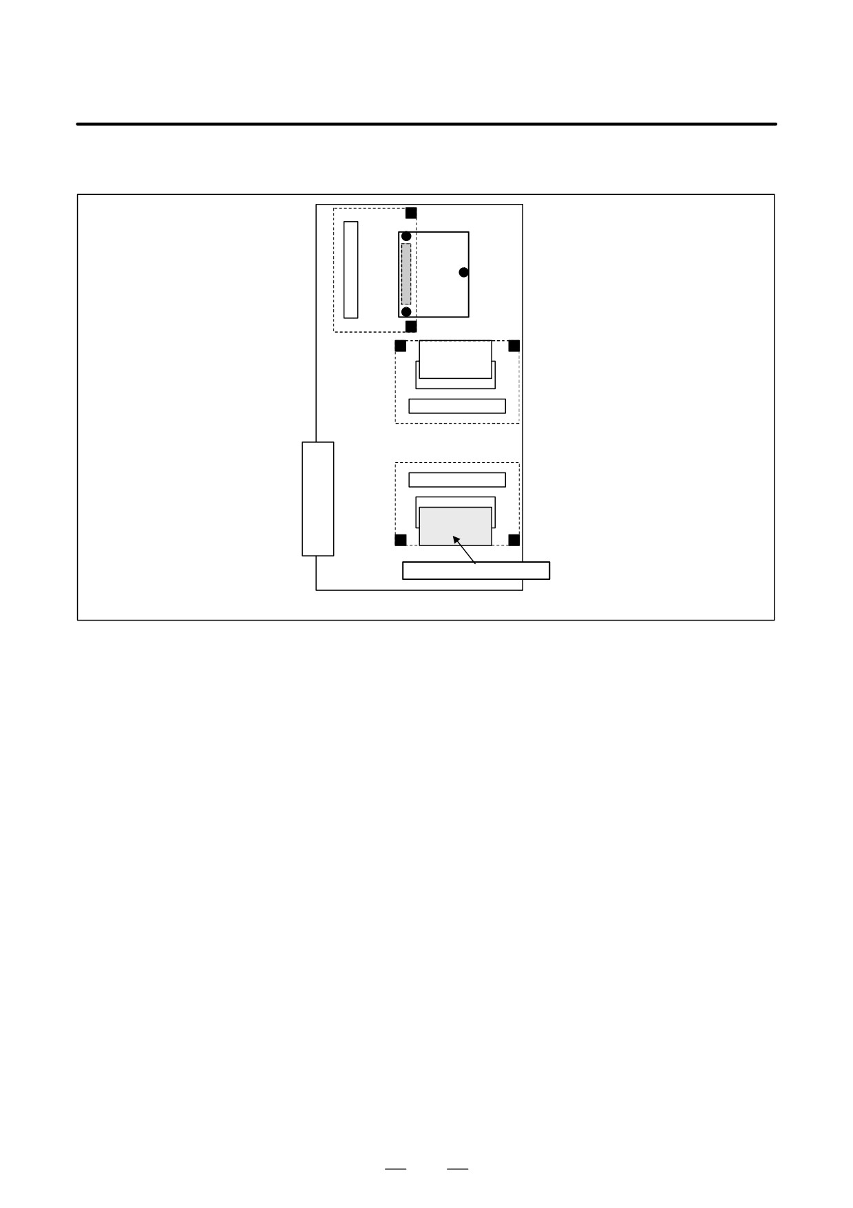
[For the stand-alone type]
The FROM/SRAM module
FROM/SRAM module
is installed under the axis
control card.
Main CPU board
795
11. TROUBLESHOOTING
B-63525EN/02
11.27
ALARMS 910 AND
911 (SRAM PARITY)
Causes and actions
A parity error occurred in the SRAM used to store data such as parameters
and machining programs.
This alarm is issued if the battery has run down or if the data in the SRAM
is destroyed due to some external cause. Or, the SRAM module,
motherboard, and option PCB may be defective.
D Checking the battery
The battery is rated 3 V. A battery alarm is issued and “BAT” flashes on
the screen if the voltage of the battery drops to 2.6 V.
If a battery alarm is issued, replace the battery with a new one promptly.
D Performing memory all
Perform a memory all clear operation, then start up the CNC.
clear
Alternatively, if a backup of the data in the SRAM has been made, use the
backup to restore the data. To back up and restore the data in the SRAM,
use the boot system.
D Replacing the
If memory all clear or the restoration of the data with a backup does not
FROM/SRAM module
solve the problem, replace the FROM/SRAM module.
After replacing the FROM/SRAM module, perform a memory all clear
operation and start up the CNC. All the data must be re-loaded.
If a backup is available, restore the data using the backup, then start up
the CNC.
D Motherboard
If any of the above actions does not solve the problem, replace the
motherboard.
796
B-63525EN/02
11.TROUBLESHOOTING
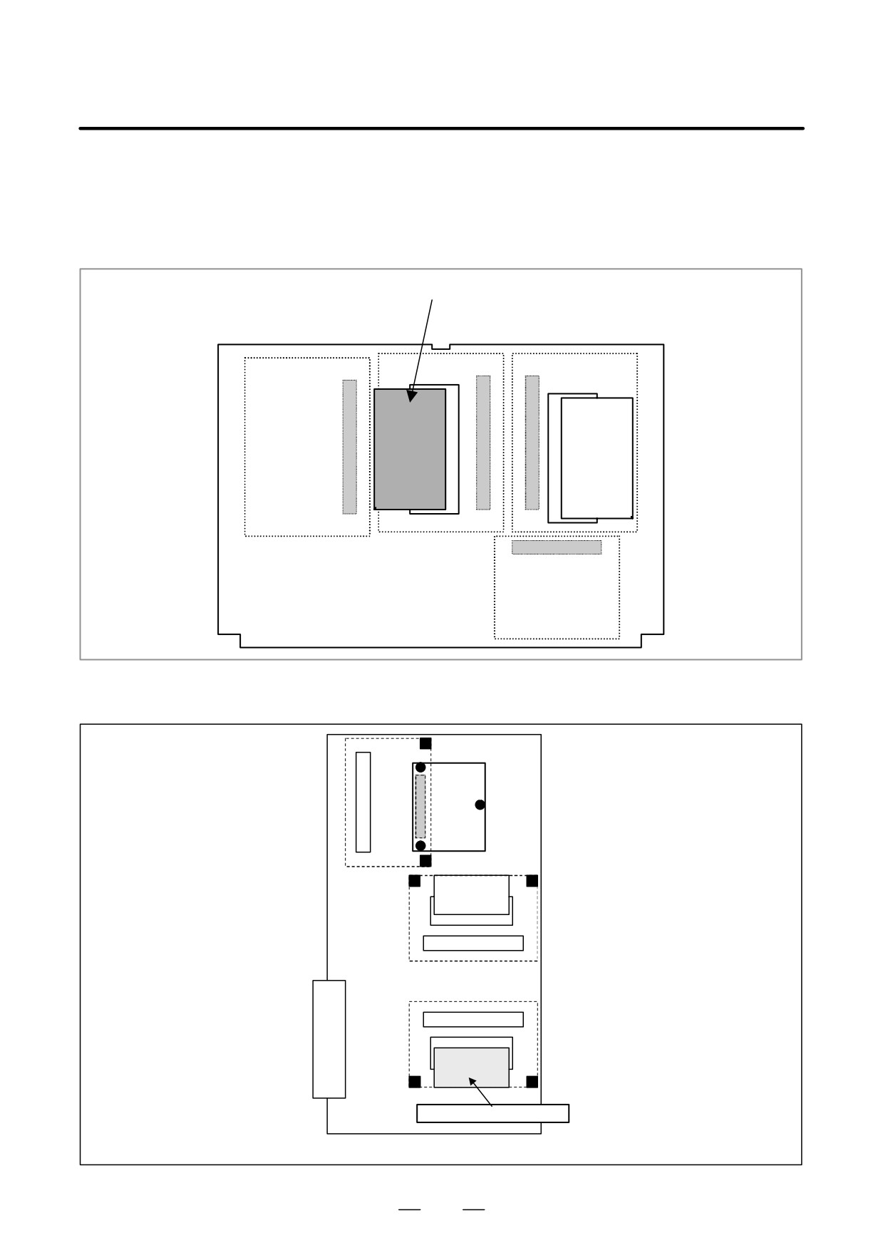
D Installation position of
the FROM/SRAM module
[For the LCD-mounted type]
FROM/SRAM module
[For the stand-alone type]
The FROM/SRAM module
FROM/SRAM module
is installed under the axis
control card.
Main CPU board
797
11. TROUBLESHOOTING
B-63525EN/02
D SRAM parity on the
If alarm 972 is issued, indicating on the screen that an SRAM parity error
loader control board or
occurred on the loader or Symbol CAPi T, take appropriate action on the
Symbol CAPi T board
loader control board or Symbol CAPi T board.
The SRAM for the loader control board and the Symbol CAPi T board is
installed on the boards themselves.
Screen display example
SYSTEM ALARM
972 NMI OCCURRED IN OTHER MODULE
SLOT 01
910 SRAM PARITY : (BYTE 0) <LC
798
B-63525EN/02
11.TROUBLESHOOTING
11.28
ALARMS 912 TO 919
(DRAM PARITY)
Causes and actions
The management software for the CNC is loaded from the FROM to the
DRAM at power on, so that it is executed on the DRAM.
A parity error occurred on this DRAM.
These alarms occur if the data on the DRAM is destroyed due to some
external cause or if the CPU card is defective.
D Replacing the CPU card.
Replace the CPU card.
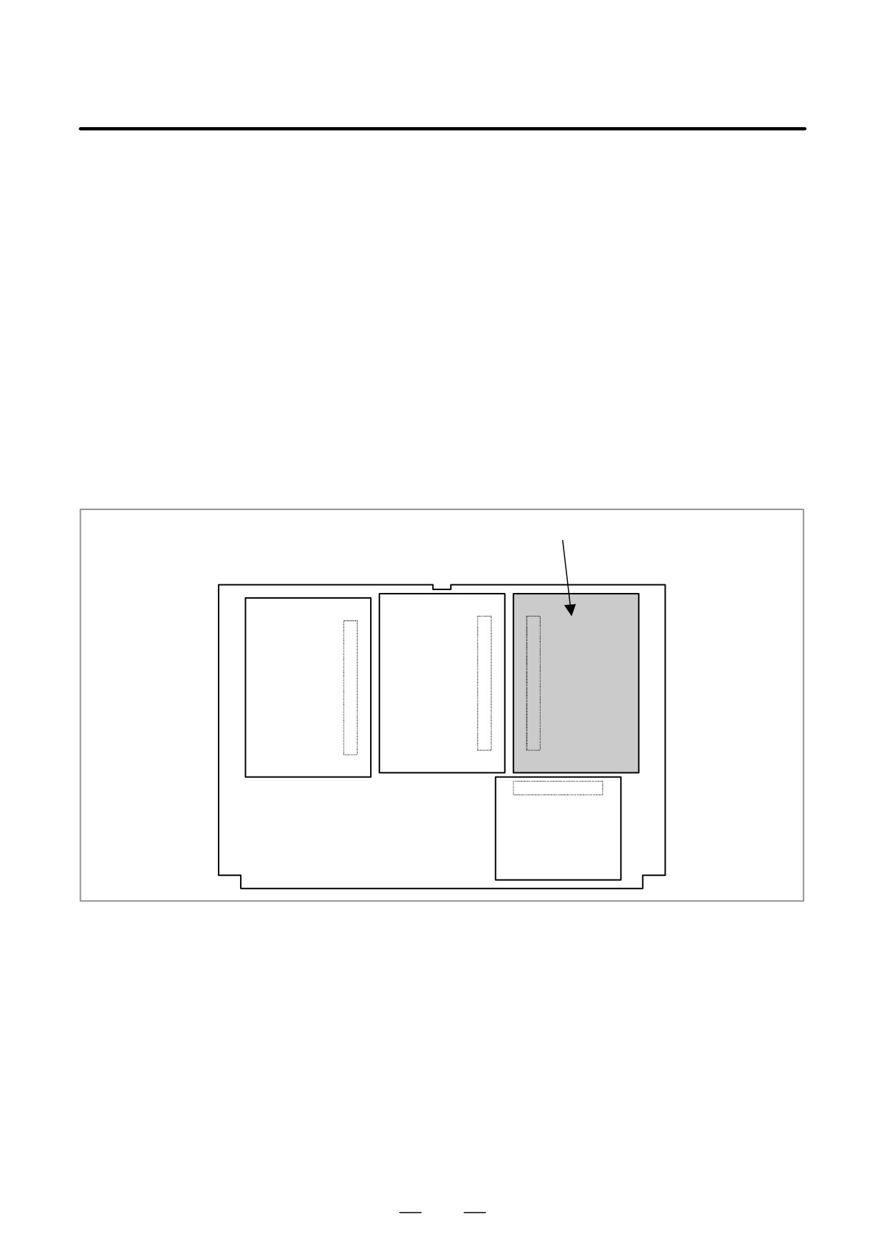
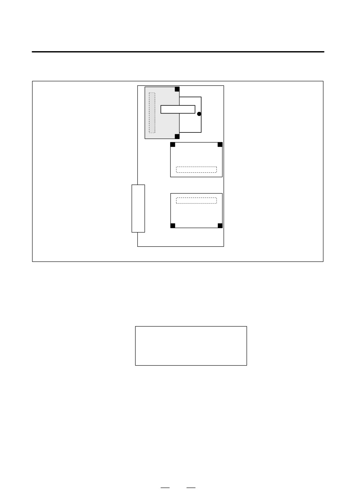
D Installation position of
the CPU card
[For the LCD-mounted type]
CPU card
799
11. TROUBLESHOOTING
B-63525EN/02
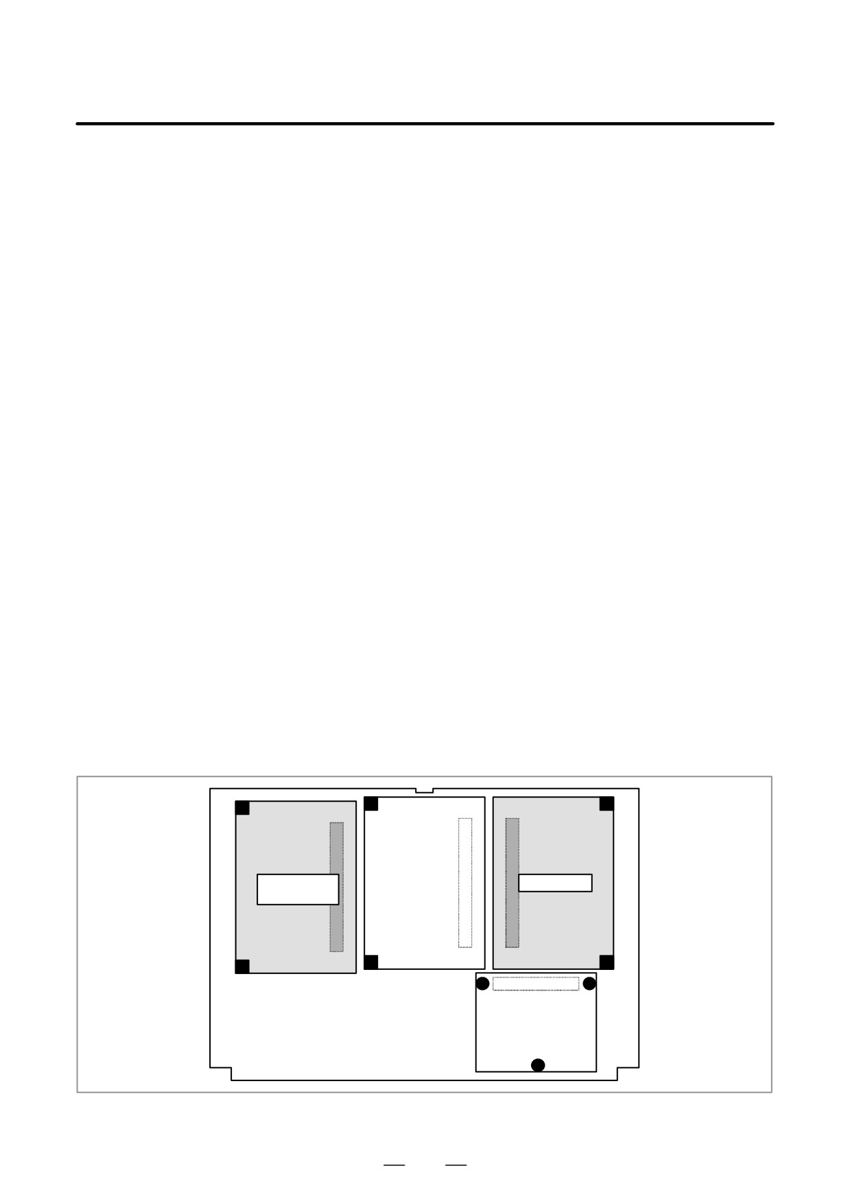
[For the stand-alone type]
CPU card
Main CPU board
D DRAM parity on an
If alarm 972 is issued, indicating on the screen that a DRAM parity error
option board
occurred on an option board, take appropriate action on the option board
on which the DRAM parity error occurred.
Some option boards have a circuit equivalent to the CPU card installed
on the boards themselves. See the hardware chapter for details.
Screen display example
SYSTEM ALARM
972 NMI OCCURRED IN OTHER MODULE
SLOT 01
DRAM PARITY : (BYTE 0) <SUB
800
B-63525EN/02
11.TROUBLESHOOTING
11.29
ALARMS 920 AND
921 (SERVO
ALARMS)
Causes and actions
A watchdog error or RAM parity error occurred in the circuit on an axis
control card.
Alarm 920 indicates that either of the above errors occurred in the control
circuit for axes 1 to 4. Alarm 921 indicates that either of the above errors
occurred in the control circuit for axes 5 to 8.
The optical cable, axis control cards, CPU card, or motherboard may be
defective.
D Watchdog error
The servo control circuit monitors the operation of the main CPU. If a
fault occurs in the CPU or its peripheral circuit, so that the watchdog timer
is not reset, a watchdog error occurs.
D Replacing the optical
Replace the optical cable. A defective optical cable may cause this
cable
problem.
D Replacing the axis
Replace the axis control cards.
control cards
D Replacing the CPU card
Replace the CPU card.
D Replacing the
If any of the above actions does not solve the problem, replace the
motherboard (main CPU
motherboard.
board)
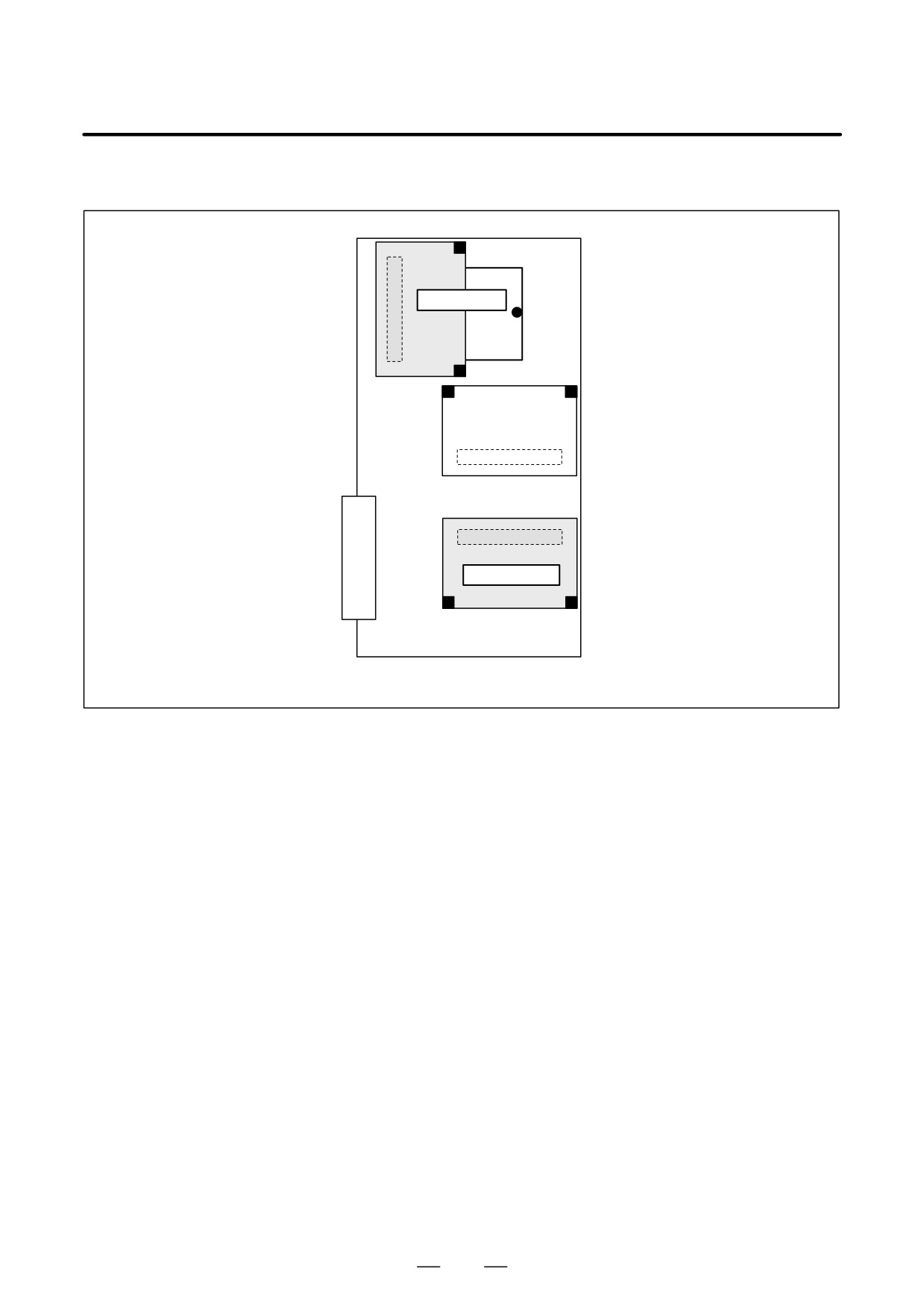
D Installation position of
each card
[For the LCD-mounted type]
Axis control
CPU card
card
801
11. TROUBLESHOOTING
B-63525EN/02
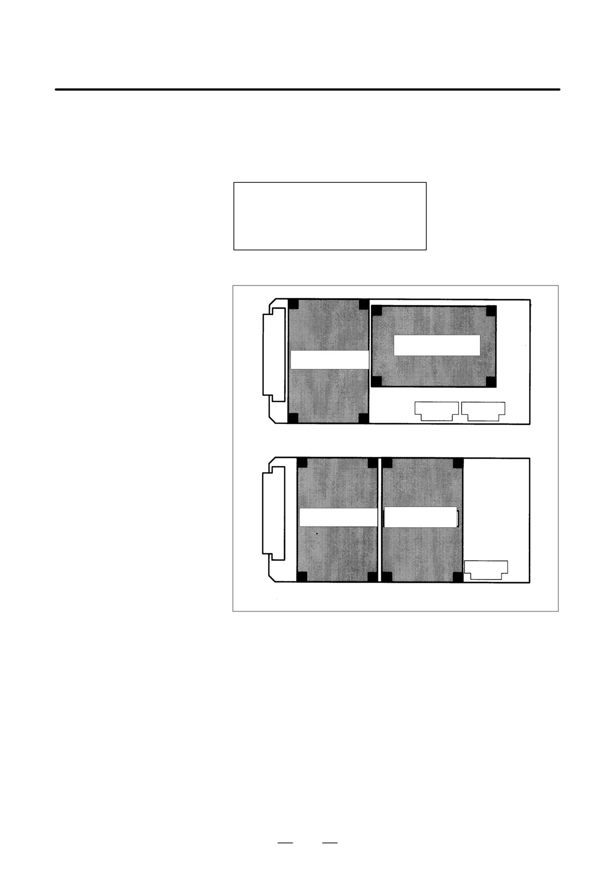
[For the stand-alone type]
CPU card
Axis control card
Main CPU board
802
B-63525EN/02
11.TROUBLESHOOTING
D Servo alarm on the
If alarm 972 is issued, indicating on the screen that a servo alarm occurred
sub-CPU board or loader on the sub-CPU or loader, take appropriate action on the sub-CPU board
control board
or loader control board.
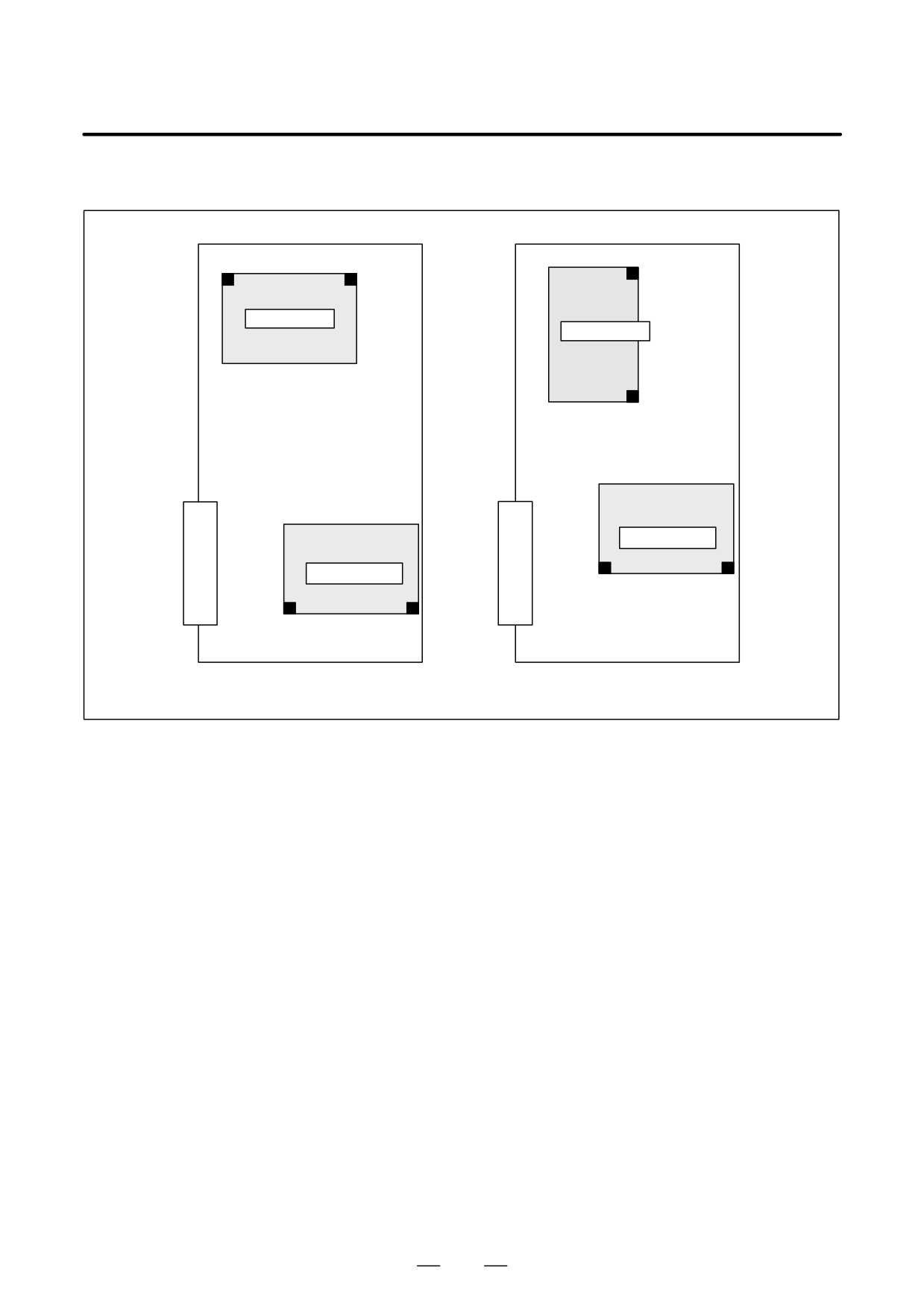
Screen display example
SYSTEM ALARM
972 NMI OCCURRED IN OTHER MODULE
SLOT 01
920 SERVO ALARM <SUB
[For the LCD-mounted type]
CPU card
Axis control card
Sub-CPU board
Axis control card
CPU card
Loader control board
803
11. TROUBLESHOOTING
B-63525EN/02
[For the stand-alone type]
CPU card
CPU card
Axis control card
Axis control card
Sub CPU board
Loarder control board
804
B-63525EN/02
11.TROUBLESHOOTING
11.30
ALARM 926 (FSSB ALARM)
Causes and actions
A fault occurred on the FSSB (serial servo bus) that connects servo
amplifiers to the CNC.
This alarm is issued if a fault occurs in any of the axis control cards
making up the FSSB, optical cables, and servo amplifiers.
D Identifying the defective
Use the LEDs on the servo amplifiers.
location
Using the
7-segment LEDs installed on the servo amplifiers, the
defective location can be identified.
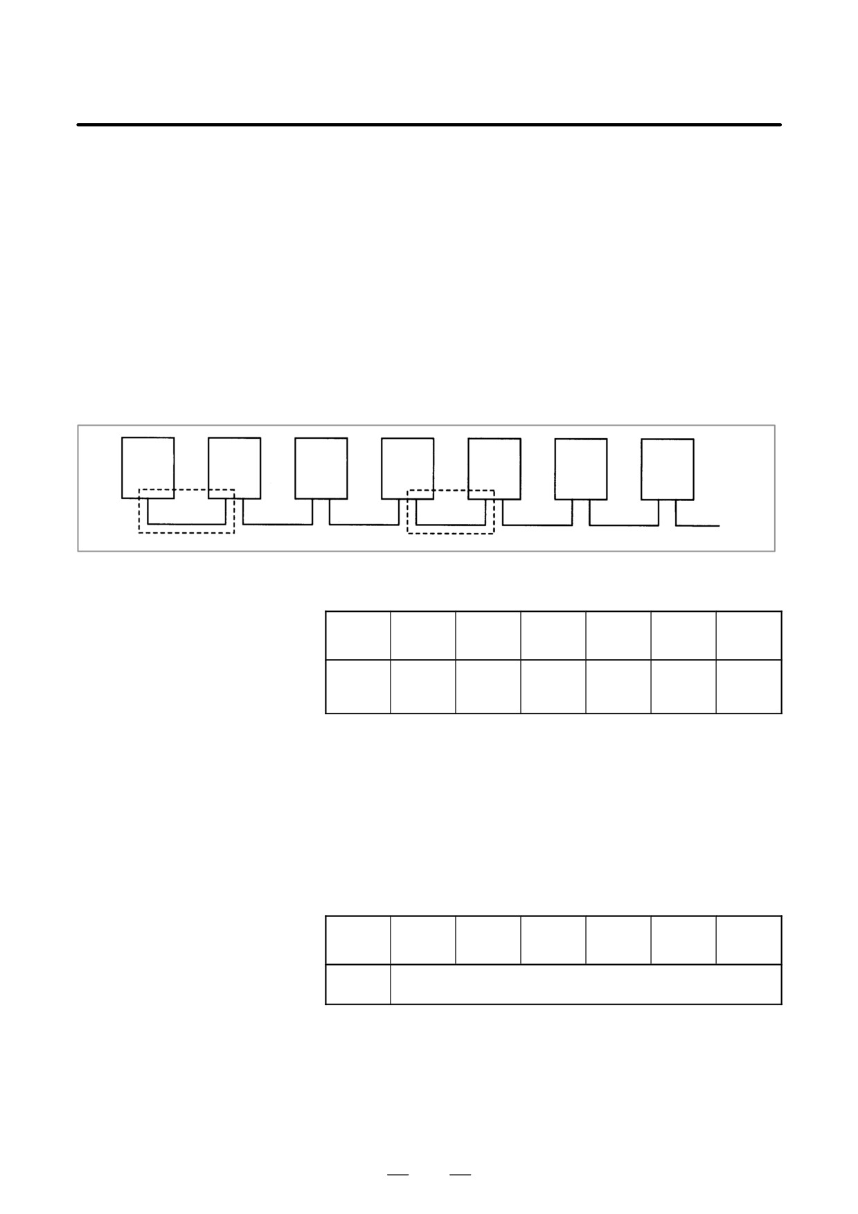
FSSB connection
example
Amplifier
Amplifier
Amplifier
Amplifier
Amplifier
Amplifier
CNC
0
1
2
3
4
5
B
A
If portion A, indicated by dotted line, contains the defective location, the
LEDs on the servo amplifiers will be as shown in the table below.
Amplifier
Amplifier
Amplifier
Amplifier
Amplifier
Amplifier
Amplifier
No.
0
1
2
3
4
5
“L”
LED
“-”
“-”
or
“U”
“U”
“U”
display
“-”
In this case, any of the following locations may be defective:
(1) Optical cable connecting together the servo amplifier whose LED is
“L” or “-” and that whose LED is “U”. In the above figure, the optical
cable in portion A may be defective.
(2) Either of the servo amplifier whose LED is “L” or “-” and that whose
LED is “U”. In the above figure, either amplifier 2 or 3 may be
defective.
If portion B, indicated by dotted line, contains the defective location, the
LEDs on the servo amplifiers will be as follows:
Amplifier
Amplifier
Amplifier
Amplifier
Amplifier
Amplifier
Amplifier
No.
0
1
2
3
4
5
LED
“-” or “U”
display
In this case, any of the following locations may be defective:
(1) Optical cable connected to the CNC. In the above figure, the optical
cable in portion B may be defective.
(2) Any of the axis control cards in the CNC
(3) First servo amplifier connected. In the above figure, amplifier 0 may
be defective.
805
11. TROUBLESHOOTING
B-63525EN/02
D Identifying the defective
Use the display on the CNC screen
location
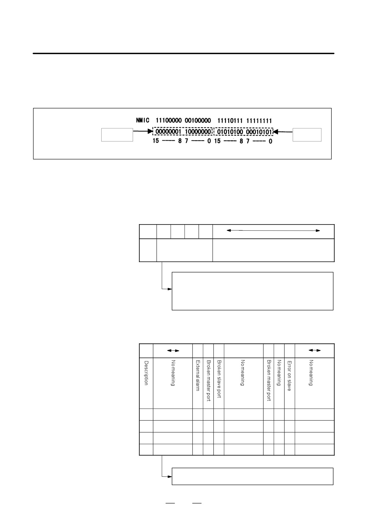
If alarm 926 is issued, information such as the following is displayed at
the bottom of the CNC screen. It can be used to identify the defective
location.
MODE
STATUS
information
information
Bits
Bits
Bits 12 to 15 of the MODE information indicate the number of the slave
in which the alarm occurred. The unit nearest the CNC (such as a servo
amplifier) is assigned a slave number of “0”. For a 2-axis amplifier, for
example, one number is assigned for the first axis, and the next number
is assigned for the second.
Details of the MODE information
Bit
15
14
13
12
11
0
De-
Number of the slave in
No meaning
scrip-
which the alarm oc-
tion
curred
0000: Indicates that the alarm occurred in slave 0.
0001: Indicates that the alarm occurred in slave 1.
:
:
1001: Indicates that the alarm occurred in slave 9.
Using the bits of the STATUS information, the fault can be estimated.
Details of the STATUS information
Bit
15
12
11
10
9
87
6
5
4
3
0
A
xxxx
0
0
0
xxx
1
x
0
xxxx
A
xxxx
0
1
0
xxx
0
x
1
xxxx
B
xxxx
0
0
1
xxx
0
x
1
xxxx
C
xxxx
1
0
0
xxx
0
x
1
xxxx
The STATUS information matches any of the patterns A, B, and C.
(x indicates a bit that may be either 0 or 1.)
806
B-63525EN/02
11.TROUBLESHOOTING
If the pattern of the STATUS information is A
(1) The optical cable that connects together the slave corresponding to bits
12 to 15 of the MODE information and the preceding slave may be
defective. Or, either of the slaves connected together with that optical
cable may be defective.
(2) The voltage of the power supplied to the slave amplifier dropped, or
a power fault occurred in the amplifier.
(3) Any of the axis control cards in the CNC may be defective.
If the pattern of the STATUS information is B
(1) The optical cable that connects together the slave corresponding to bits
12 to 15 of the MODE information and the preceding slave may be
defective. Or, either of the slaves connected together with that optical
cable may be defective.
(2) The voltage of the power supplied to the slave amplifier dropped, or
a power fault occurred in the amplifier.
If the pattern of the STATUS information is C
(1) The slave corresponding to bits 12 to 15 of the MODE information
may be defective.
(2) The voltage of the power supplied to the slave amplifier dropped, or
a power fault occurred in the amplifier.
D Power fault in a servo
If a power fault occurs in a servo amplifier, the FSSB alarm is issued. A
amplifier
power fault occurs, causing the FSSB alarm to be issued, if the amplifier
control power supply voltage drops, if the +5 V conductor of the pulse
coder cable is ground, or for other reasons.
D Replacing the axis
If any of the axis control cards are found defective because of the above
control card
diagnosis, replace the axis control card on the motherboard (main CPU
board).
807
11. TROUBLESHOOTING
B-63525EN/02
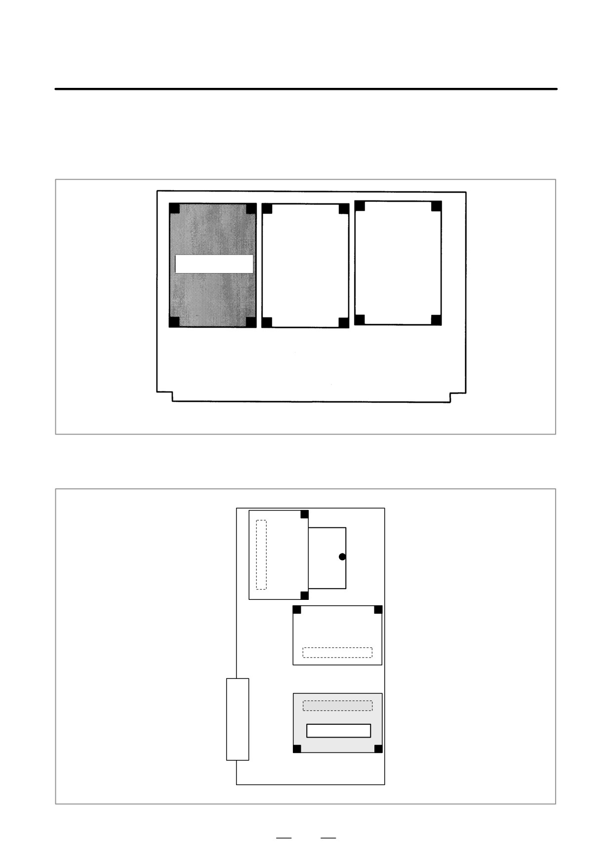
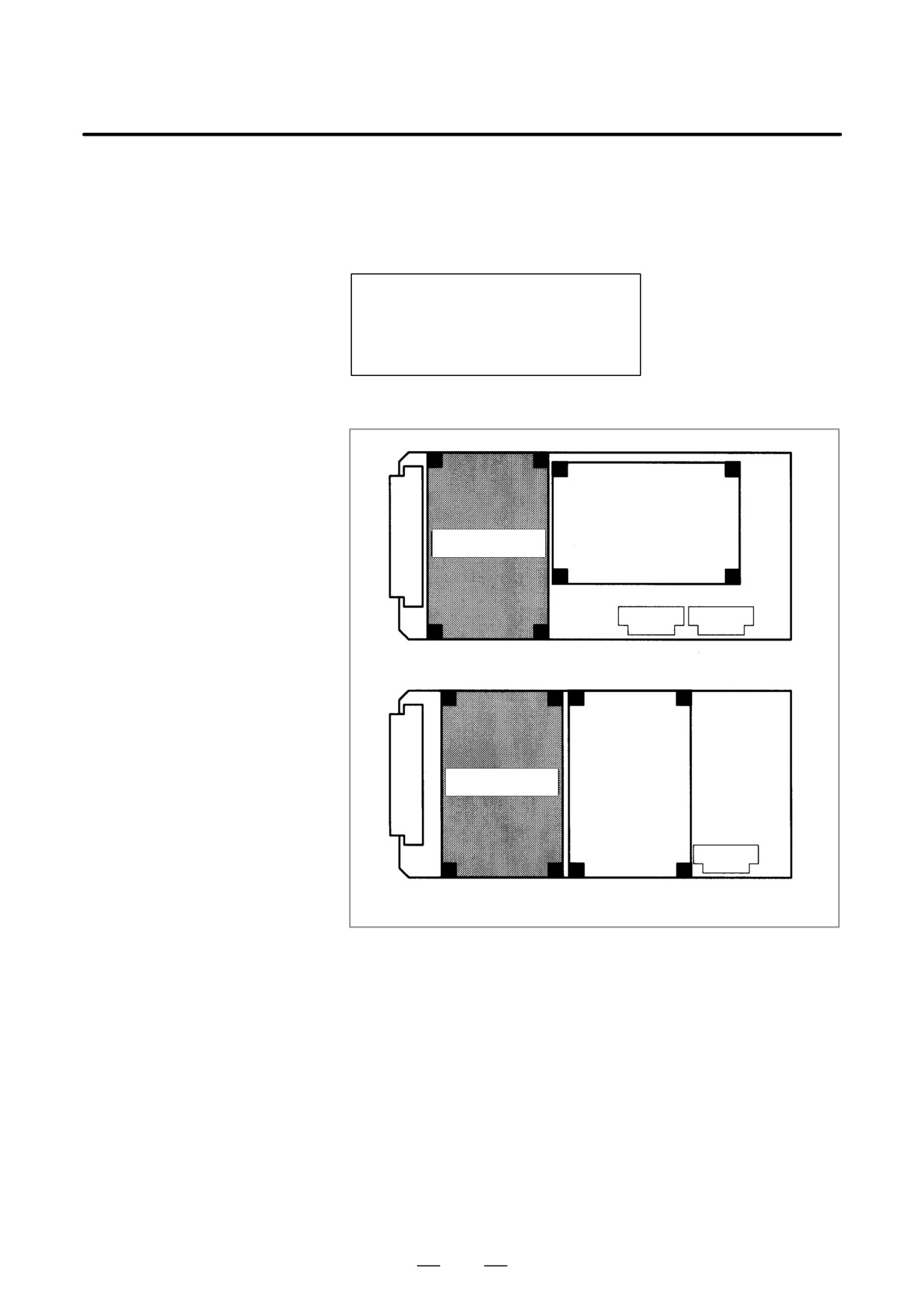
D Installation position of
the axis control card
[For the LCD-mounted type]
Axis control card
Motherboard
[For the stand-alone type]
Axis control card
Main CPU board
808
B-63525EN/02
11.TROUBLESHOOTING
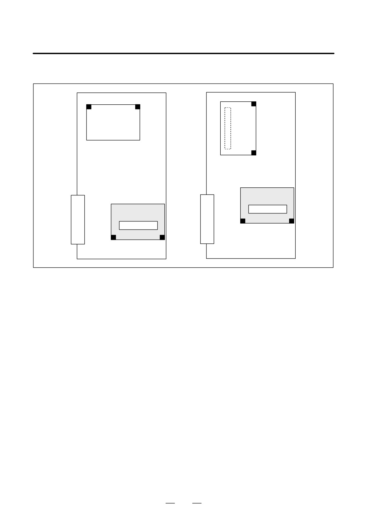
D FSSB alarm on the
If alarm 972 is issued, indicating on the screen that an FSSB alarm
sub-CPU board or loader occurred on the sub-CPU or loader, take appropriate action on the
control board
sub-CPU board or loader control board.
Screen display example
SYSTEM ALARM
972 NMI OCCURRED IN OTHER MODULE
SLOT 01
926 FSSB ALARM <SUB
[For the LCD-mounted type]
Axis control card
Sub-CPU board
Axis control card
Loader control card
809
11. TROUBLESHOOTING
B-63525EN/02
[For the stand-alone type]
Axis control card
Axis control card
Sub CPU board
Loarder control board
810
B-63525EN/02
11.TROUBLESHOOTING
11.31
ALARM 930
(CPU INTERRUPT)
Causes and actions
An interrupt that can never be generated during normal operation was
generated.
The cause of the fault cannot be identified, but the fault may have occurred
in the peripheral circuit of the CPU.
If the problem is solved by turning the power off and then on again, the
problem may be attributable to noise.
D Replacing the CPU card,
motherboard
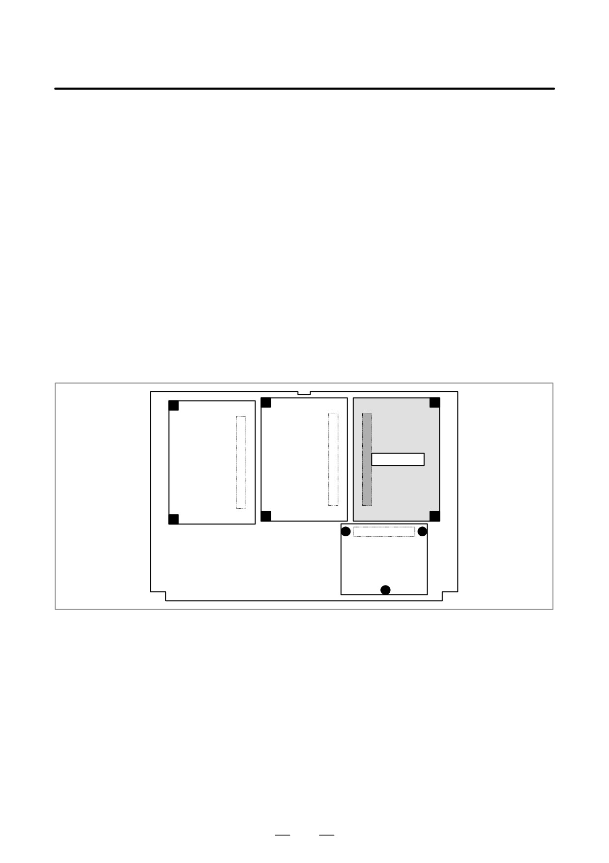
D Installation position of
each card
[For the LCD-mounted type]
CPU card
811