FANUC Series 16i/160i/160is-MODEL B, Series 18i/180i/180is-MODEL B, Series 21i/210i/210is-MODEL B. MAINTENANCE MANAUL - page 14
5. MATTERS COMMON TO BOTH LCD-MOUNTED TYPE
AND STAND-ALONE TYPE i SERIES (HARDWARE)
B-63525EN/02
D Cleaning the fan of the
heat exchanger
Procedure for cleaning the fan of the heat exchanger
1
Demount the heat exchanger from the unit, then remove dust and mist
from the fan by blowing air or by using a dry waste cloth or brush.
When the fan is dirty extremely
1
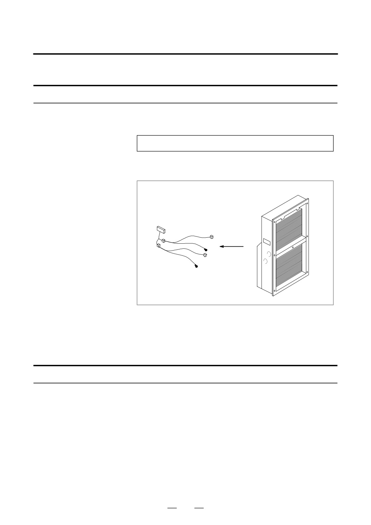
Detach the internal fan unit, terminal block, and cables from the main
body.
Main body
Terminal block, cables
2
Clean the fan by using a brush and a solution of water and neutral
detergent. At this time, be careful not to bend a vane.
3
After cleaning, dry the heat exchanger and fan unit sufficiently.
D Reassembly
Procedure for reassembly after cleaning
After cleaning the fan unit and heat exchanger, follow the steps below.
1
Reinstall the terminal block and cables at the original locations.
2
Reinstall the fan unit at the original location. At this time, reconnect
the fan power cable and ground wire correctly.
362
5. MATTERS COMMON TO BOTH LCD-MOUNTED TYPE
B-63525EN/02
AND STAND-ALONE TYPE i SERIES (HARDWARE)
5.4
LIQUID CRYSTAL
DISPLAY (LCD)
Brightness of the
When the ambient temperature is low, the brightness of the LCD
monochrome LCD
decreases.
(The LCD screen is dark particularly immediately after the
power is turned on.) This phenomenon is not a failure but is a property
specific to the LCD. When the ambient temperature increases, the LCD
screen becomes brighter. The monochrome LCD has a brightness control
function. For the method of adjustment, see Section 1.17.
LCD with a touch panel
The touch panel is operated by directly touching the LCD screen. For this
operation, be sure to use a FANUC-supplied pen (A02B-0236-K111)
dedicated to the touch panel. If a sharp-pointed pen is used, for example,
to touch the LCD screen, the LCD surface may be flawed or damaged.
Moreover, do not touch the LCD screen directly with a finger. Otherwise,
the operability of the LCD may deteriorate, and the LCD screen may get
dirty.
Protection sheet for the
A protection sheet is attached the face of an LCD with a touch panel to
touch panel
protect the thin film of the touch panel and LCD. If the protection sheet
is damaged, it can be replaced.
(The protection sheet is a consumable
part.)
Replacing the protection
sheet
D Materials used
1)
Protection sheet A02B-0236-K110: For 10.4” LCD with touch
panel and soft key
A02B-0236-K130: For 10.4” LCD with touch
panel
2)
Neutral detergent
(detergent that can clean oily dirt off = detergent
for kitchen can be used)
3)
Soft cloth
(such as towel)
D Replacement procedure
1)
Before replacement
<1> Turn off the power to the machine.
<2> Peel off the old protection sheet from the surface of the touch
panel.
<3> Wipe off adhesive residue if any on the screen surface with
alcohol.
<4> Use the detergent to remove oil or dirt stuck to the surface of the
touch panel.
<5> With a soft, damp cloth, wipe off detergent completely.
D If the touch panel surface becomes cloudy, oil is still left on
the surface. Remove oil completely.
D If oil or detergent is left on the surface of the touch panel, the
protection sheet cannot adhere to the panel completely and
will sometimes peel off easily.
363
5. MATTERS COMMON TO BOTH LCD-MOUNTED TYPE
AND STAND-ALONE TYPE i SERIES (HARDWARE)
B-63525EN/02
<6> With a dry soft cloth, wipe off moisture completely.
2) Applying the protection sheet
2-1) For A02B-0236-K110
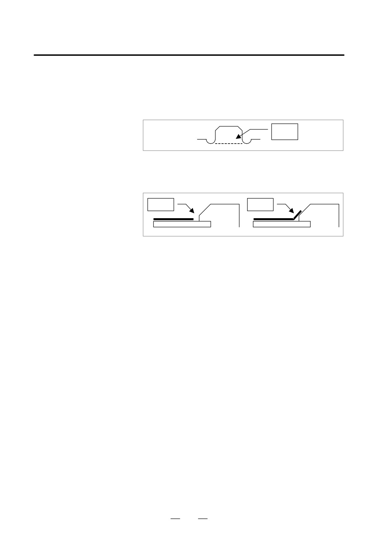
<1> Fold the tab over the front side (the side opposite to the
backing sheet).
Fold
<2> Peel off the backing sheet.
<3> Position the sheet, then attach the upper and lower sides
of the sheet first. Check that the sides of the protection
sheet do not touch the escutcheon.
OK
NG
<4> Attach the right and left sides of the protection sheet
while pushing out air between the touch panel and
protection sheet.
D With part of the protection sheet kept stuck to the
touch panel, do not attempt to correct the position of
the protection sheet by pulling the sheet.
<5> Press the adhesive parts of the four sides, and attach the
entire sheet completely.
D Check that the four corners and four sides of the
protection sheet do not float.
364
5. MATTERS COMMON TO BOTH LCD-MOUNTED TYPE
B-63525EN/02
AND STAND-ALONE TYPE i SERIES (HARDWARE)
2-2) For A02B-0236-K130
<1> Peel off the white film attached on the back (facing the
LCD) of the new protection sheet.
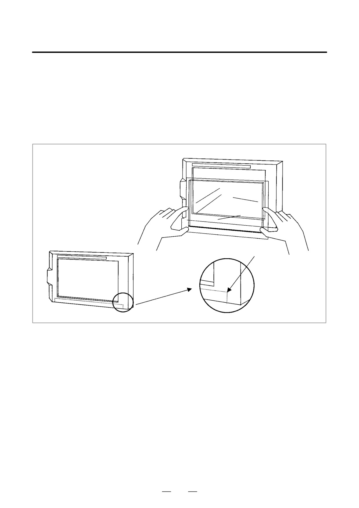
<2> Attach the protection sheet so that it is to the lower-left
of the replacement tab. At this time, align the overhang
edge at bottom of the escutcheon with the corresponding
part of the protection sheet. In addition, prevent dust
from entering between the LCD and the protection sheet.
Guide position
<3> Attach the four sides while pushing out air between the
touch panel and the protection sheet.
D Do not pull the protection sheet to correct its position
with the part of the sheet kept stuck to the touch panel.
<4> Press the adhesive parts of the four sides, and attach the
sheet completely.
D Check that the four corners and four sides of the
protection sheet do not float.
3) Checks after replacement
<1> Check that there is no wrinkle on the surface of the protection
sheet.
<2> After power-on, check that there is no touch panel portion kept
pressed.
<3> Press the touch panel, and check that correct operation takes
place.
365
5. MATTERS COMMON TO BOTH LCD-MOUNTED TYPE
AND STAND-ALONE TYPE i SERIES (HARDWARE)
B-63525EN/02
Touch panel
compensation
D Condition that requires
Touch panel compensation is required:
compensation
1
When the LCD unit is replaced
2
When the touch panel is replaced
3
When the touch panel control printed circuit board is replaced
4
Memory is all cleared.
D Parameter setting
#7
#6
#5
#4
#3
#2
#1
#0
3113
DTPCL
[Data type]
Bit
#5 (DTPCL)
The compensation function for the touch panel on the display is:
0 : Disabled
1 : Enabled
D Method of compensation
1
Set bit 5 (DTPCL) of parameter No. 3113 to 1.
2
Press function key <SYSTEM>.
3
Pressing the continuous menu key several times displays soft key [TP
CAL].
4
Pressing soft key [TP CAL] displays the touch panel compensation
screen.
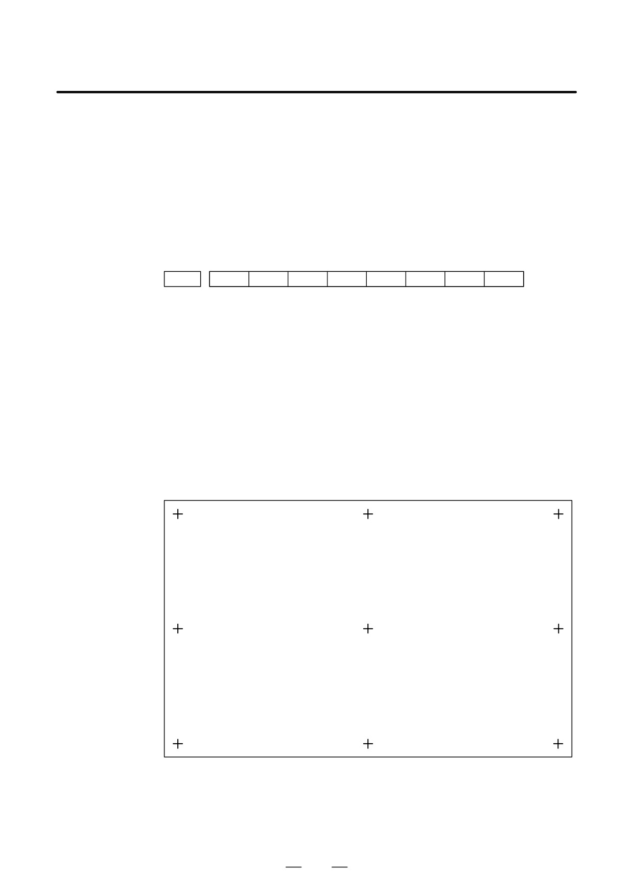
CALIBRATION OF TOUCH PANEL
PLEASE PUSH CALIBRATED POINTS.
IF CALIBRATION IS ENDED, PLEASE PUSH <INPUT> KEY.
IF CALIBRATION IS CANCELED, PLEASE PUSH <CAN> KEY.
IF OPERATION IS ENDED, PLEASE PUSH FUNCTION KEY.
5
Press the nine compensation points (marked with +) with touch panel
pen. You may press the nine points in any order. When you press a
+ mark correctly, the + mark blinks. When you press a + point
incorrectly, the message
“CALIBRATED POINT DOES NOT
MATCH, PLEASE PUSH AGAIN.” appears.
366
5. MATTERS COMMON TO BOTH LCD-MOUNTED TYPE
B-63525EN/02
AND STAND-ALONE TYPE i SERIES (HARDWARE)
6
After pressing all of the nine compensation points, press the
<INPUT> key to terminate compensation. To cancel compensation
or start all over again, press the <CAN> key.
7
Upon normal termination, the message
“CALIBRATION WAS
ENDED.” appears.
8
Pressing the function key exits from the touch panel compensation
screen, and terminates or stops compensation operation.
9
Upon termination of compensation operation, set bit 5 (DTPCL) of
parameter No. 3113 to 0.
NOTE
Touch panel of the CNC display unit with PC functions is
compensated by the exclusive program.
When compensating the touch panel for the is series, select
[Start] → [Settings] → [Control Panel] → [Adjusting Stylus],
instead of using the above method.
367
5. MATTERS COMMON TO BOTH LCD-MOUNTED TYPE
AND STAND-ALONE TYPE i SERIES (HARDWARE)
B-63525EN/02
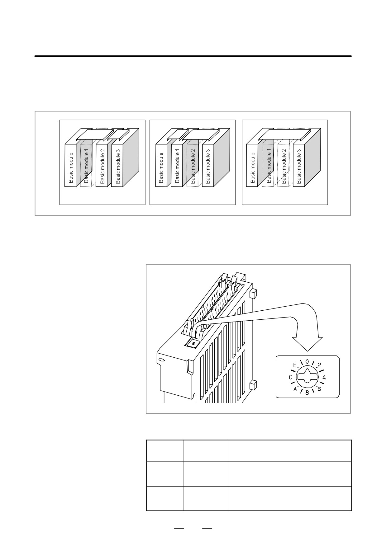
By changing the setting (rotary switch) on an expansion module, a
5.5
connection can be made to skip an expansion module or expansion
DISTRIBUTED I/O
modules as shown below.
SETTING
When expansion module 1 is
When expansion module 2 is
When expansion modules 1 and
skipped
skipped
2 are skipped
Method of setting (control and setting method)
A control (rotary switch) is provided on the location shown below of each
expansion module. When changing the setting, turn the rotary switch
with a flat-blade screwdriver with a tip diameter of about 2.5 mm.
Each setting position of the rotary switch has the meaning as indicated
below.
Setting
Indication
Meaning of setting
position
0
0
Standard setting. The rotary switch is set to this
position at the time of shipment from FANUC.
This setting is not skipped an expansion module.
1
-
Set the rotary switch of an expansion module to this
position when the one preceding expansion module
is skipped.
368
5. MATTERS COMMON TO BOTH LCD-MOUNTED TYPE
B-63525EN/02
AND STAND-ALONE TYPE i SERIES (HARDWARE)
Setting
Indication
Meaning of setting
position
2
2
Set the rotary switch of an expansion module to this
position when the two preceding expansion mod-
ules are skipped.
3
-
Setting prohibited
4 to F
4, -, 6, -,
4, 8, or C has the effect of 0.
8, -, A, -,
5, 9, or D has the effect of 1.
C, -, E, -,
6, A, or E has the effect of 2.
7, B, or F has the effect of 3. (← setting prohibited)
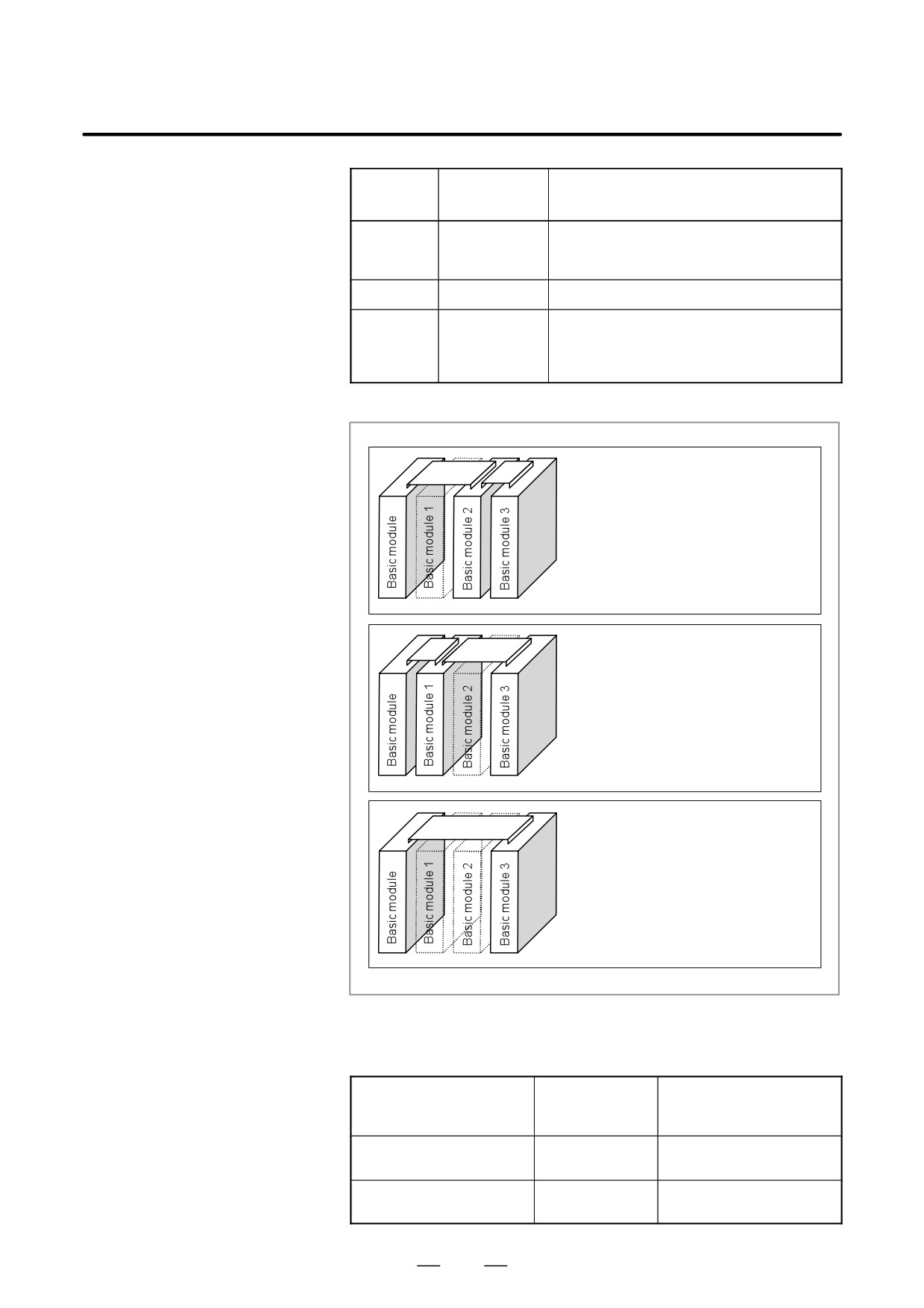
Examples of setting
(When expansion module 1 is skipped)
Set the rotary switch of expansion module 2
to setting position = 1. Do not change the
setting (setting position = 0) of expansion
module 3.
(When expansion module 1 and expansion
module 2 are skipped)
Set the rotary switch of expansion module 3
to setting position = 2.
(When expansion module 2 is skipped)
Set the rotary switch of expansion module 3
to setting position = 1. Do not change the
setting (setting position = 0) of expansion
module 1.
This function was not available initially, but was recently added. This
function became available, depending on the type of module, as indicated
below.
Expansion module B (DI/DO =
A03B-0815-C003
Available starting with shipment
24/16, without a manual pulse
in June 1998 and later
generatorinterface)
Expansion module C (DO = 16,
A03B-0815-C004
Available starting with shipment
24A output)
in August 1998 and later
Expansion module D (analog
A03B-0815-C005
Available starting with shipment
input)
in August 1998 and later
369
5. MATTERS COMMON TO BOTH LCD-MOUNTED TYPE
AND STAND-ALONE TYPE i SERIES (HARDWARE)
B-63525EN/02
NOTE
To expansion module A (DI/DO = 24/16, with a manual pulse
generator interface) (A03B-0815-C002), a rotary switch is
added as the other modules are modified. However,
expansion module A is always installed at the location of
expansion module 1, so that the setting of expansion
module A need not be changed.
370
5. MATTERS COMMON TO BOTH LCD-MOUNTED TYPE
B-63525EN/02
AND STAND-ALONE TYPE i SERIES (HARDWARE)
5.6
REPLACING FUSES
WARNING
ON VARIOUS UNITS
Before replacement of a blown fuse, the cause of the blown
fuse must be corrected. So, fuse replacement work must be
done only by a person who is trained in the related
maintenance and safety requirements. When opening the
cabinet and replacing a fuse inside, be careful not to touch
the high-voltage circuits (marked with
and fitted with an
insulating cover). Touching the uncovered high-voltage
circuits presents an extremely dangerous electric shock
hazard.
For the specification of the fuse of each unit, see the list of consumables
in Appendix B.
371
5. MATTERS COMMON TO BOTH LCD-MOUNTED TYPE
AND STAND-ALONE TYPE i SERIES (HARDWARE)
B-63525EN/02
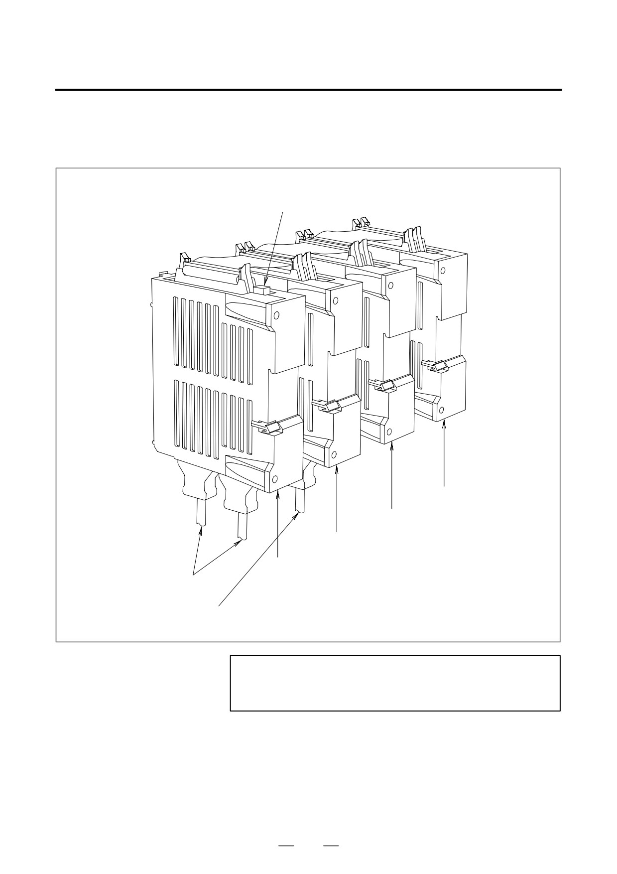
D Fuse mounting location
on the connector panel
I/O modules
Fuse
Expansion module 3
Expansion module 2
Expansion module 1
Basic module
(A03B-0815-C001)
Cable for the I/O Link
Cable for a manual pulse generator
NOTE
No fuse is provided on the expansion modules. A fuse is
provided on the basic module only.
372
5. MATTERS COMMON TO BOTH LCD-MOUNTED TYPE
B-63525EN/02
AND STAND-ALONE TYPE i SERIES (HARDWARE)
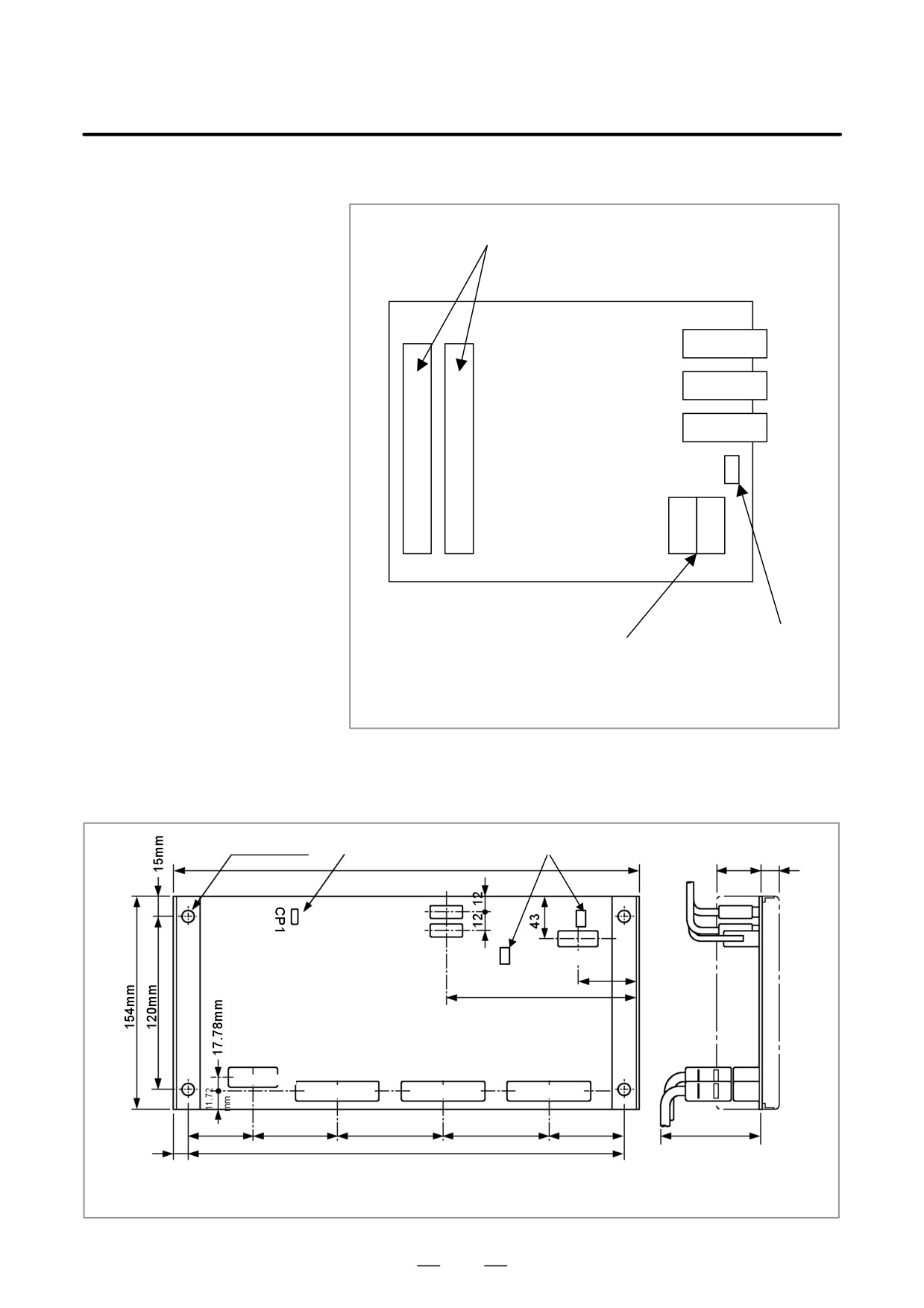
D Fuse mounting location
on the operator’s panel
I/O modules
I/O connector
JD1A
JD1B
JA3
Fuse
Power supply connector
This drawing is for A20B-2002-0470, A20B-2002-0520, and
A20B-2002-0521.
D Fuse mounting location
on the operator’s panel
connection units
4-f5MM
CP1
Fuse
336mm
50mm 10mm
3.2A FUSE
JD1B
JD1A
CP61
5A FUSE
35
155
CM4
CMB4
CM3
CM2
CM1
CMB3
CM52
CM51
MR20RM
MR50RM
MR50RM
MR50RM
20
50
50
50
31.05mm
46.99mm
88.9mm
88.9mm
66.16mm
7mm
322mm
Approx.
100mm
This drawing is for A20B-2200-0660, A20-2200-661, A16B-2202-0730, and A16B-2202-0731.
373
5. MATTERS COMMON TO BOTH LCD-MOUNTED TYPE
AND STAND-ALONE TYPE i SERIES (HARDWARE)
B-63525EN/02
D Fuse mounting locations
on the machine
operator’s panel
interface unit
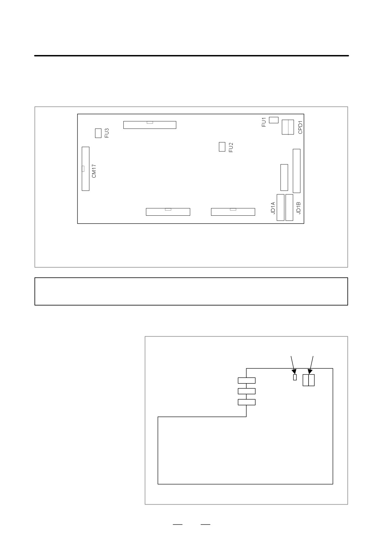
CM26
CM16
CM15
FU1: Fuse for +24V (for protection of general-purpose DO and the power supply of this printed circuit board)
FU2: Fuse for +5V (for protection of the IC power supply and manual pulse generator)
FU3: Fuse for +5E (for protection of general-purpose DI)
This drawing is for A16B-2201-0110.
NOTE
FU2 is not mounted with Edition 05A and later.
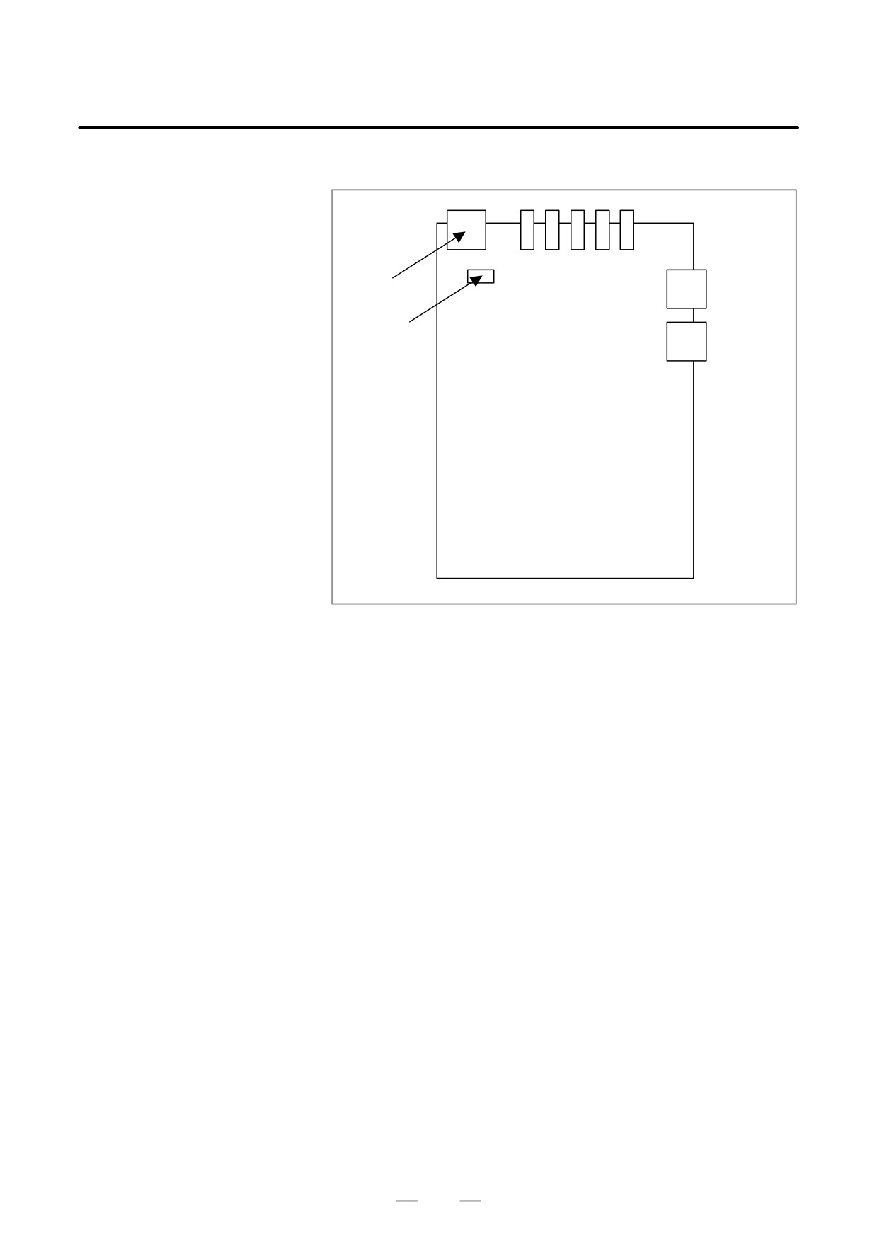
D Fuse mounting location
on the distributed I/O
machine operator’s
Power
panels
Fuse
connector
JA3
JD1A
JD1B
This drawing is for A02B-0236-C140 and A02B-0236-C141.
374
5. MATTERS COMMON TO BOTH LCD-MOUNTED TYPE
B-63525EN/02
AND STAND-ALONE TYPE i SERIES (HARDWARE)
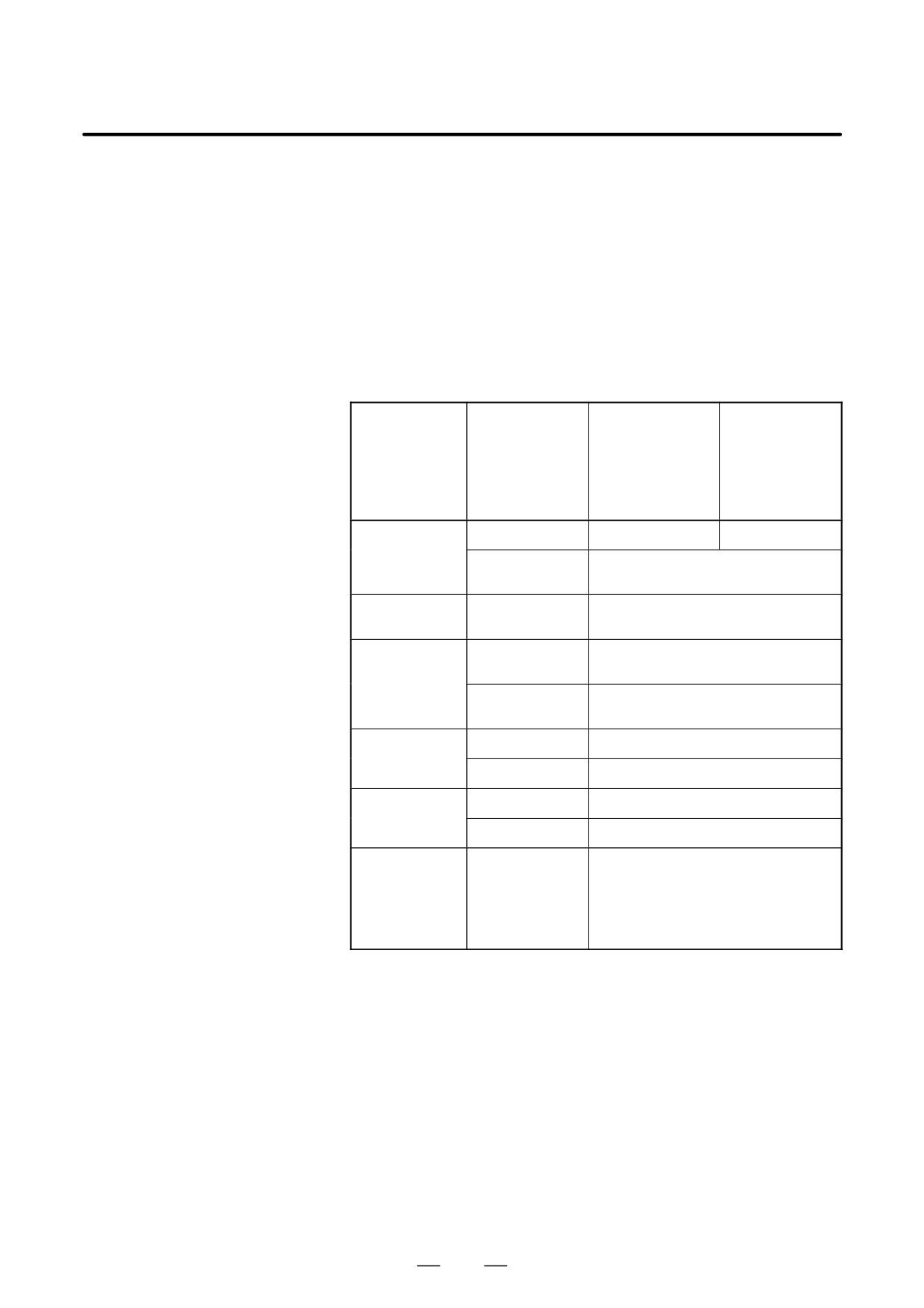
D Fuse mounting location
on the separate detector
interface unit
Power
connector
Optical
connector
Fuse
375
5. MATTERS COMMON TO BOTH LCD-MOUNTED TYPE
AND STAND-ALONE TYPE i SERIES (HARDWARE)
B-63525EN/02
The control units and various peripheral units supplied from FANUC are
5.7
designed assuming that those units are accommodated in enclosed
ENVIRONMENTAL
cabinets. The cabinets mentioned here include:
CONDITIONS
D Cabinet that is manufactured by a machine tool builder to house
OUTSIDE CABINET
control units and peripheral units
D Operation pendant that is manufactured by a machine tool builder to
house control units and an operator’s panel
D Similar products
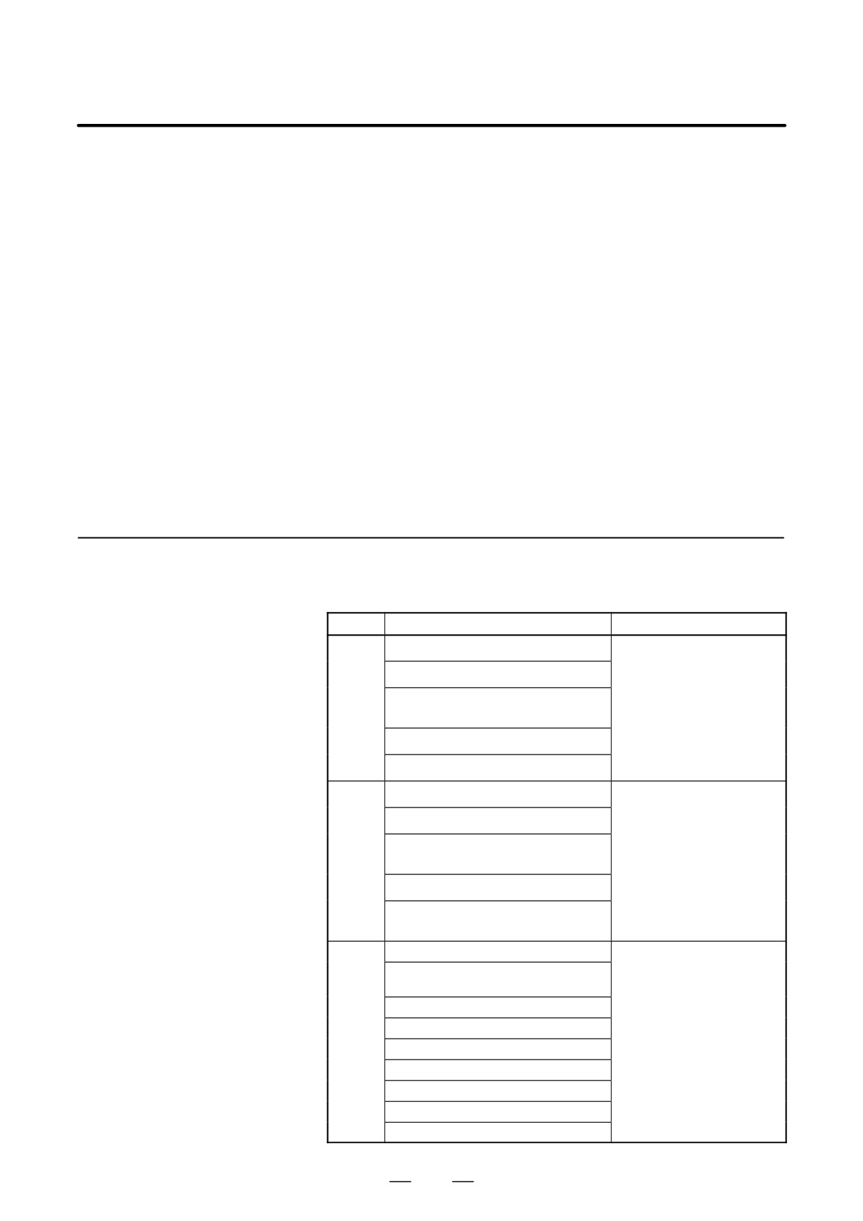
The table below indicates the environment conditions for installing
control units in these cabinets.
Condition
Display LCD-
Display stand-
mounted type
alone type con-
control unit and
trol unit
display unit (ex-
cluding units with
a data server)
Ambient
Operating
0°C to 58°C
0°C to 55°C
temperature of
units
Storage and trans-
-20°C to 60°C
portation
Change in temper-
1.1 °C/minute max.
ature
Humidity
Normal
Relative humidity: 75% or less
No condensation
Short term (not ex-
Relative humidity: 95% or less
ceeding 1 month)
No condensation
Vibration
Operating
0.5 G or less
Non-operating
1.0 G or less
Height above sea
Operating
Up to 1000m
level
Non-operating
Up to 12000m
Atmosphere
Normal machine plant environment
(When a control unit is used in an environ-
ment where the control unit is exposed to a
high level of dust and a high concentration
of coolants an organic solutions, a separate
study is required.)
376
5. MATTERS COMMON TO BOTH LCD-MOUNTED TYPE
B-63525EN/02
AND STAND-ALONE TYPE i SERIES (HARDWARE)
The CNC is becoming increasingly smaller as the surface mount
5.8
technology and custom LSI technology advance.
COUNTERMEA-
SURES AGAINST
In many cases, as the CNC becomes more compact, the mounting
locations of its constituent units become closer to a noise source in the
NOISE
power magnetics cabinet.
In general, noise is generated by electrostatic coupling, electromagnetic
induction, or a grounding loop, and is induced into the CNC.
The CNC incorporates sufficient countermeasures against external noise.
However, it is difficult to measure the level and frequency of noise
quantitatively, and many unknown factors are involved. So, to improve
the operation stability of a CNC machine tool system, noise generation
must be minimized, and the induction of generated noise into the CNC
must be suppressed.
For design of equipment including a power magnetics cabinet, take these
countermeasures on the machine side against noise into consideration.
5.8.1
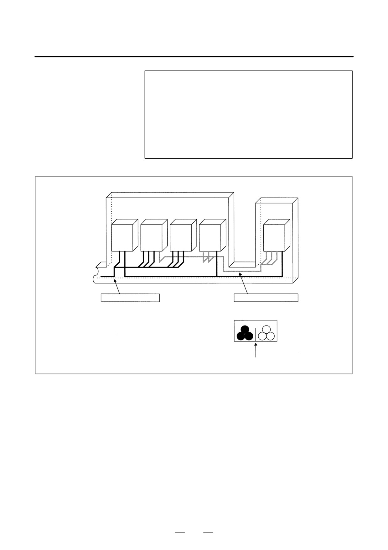
The cables used with a CNC machine tool are classified as indicated
below. Handle the cables of each group according to the descriptions in
Separation of Signal
the “Action” column.
Lines
Group
Signal
Action
Primary side AC power line
Bind the cables of this group sep-
arately from the cables of groups
Secondary side AC power line
B and C(*1), or electromagneti-
cally shield the cables of this
AC/DC power lines (including servo motor
group from the cables of groups
A
and spindle motor power lines)
B and C(*2). According to the de-
scriptions of noise suppressors
AC/DC solenoid
in Section 5.8.4, attach a spark
killer or diode to the solenoid and
AC/DC relay
relay.
DC solenoid (24 VDC)
Attach a diode to the DC solenoid
and relay.
DC relay (24 VDC)
Bind the cables of this group sep-
arately from the cables of group
DI-DO cable between I/O unit power mag-
A, or electromagnetically shield
B
netics cabinets
the cables of this group from the
cables of group A.
DI-DO cable between I/O unit machines
Separate the cables of this group
from the cables of group C as far
24-VDC input power cables for the control
as possible. Shielding is recom-
unit and its peripherals
mended.
CNC-I/O unit cable
Bind the cables of this group sep-
arately from the cables of group
Cables for position loopback and velocity
A, or electromagnetically shield
loopback
the cables of this group from the
CNC-spindle amplifier cable
cables of group A.
Separate the cables of this group
Position coder cable
from the cables of group B as far
C
Manual pulse generator cable
as possible.
Shielding according to Section
CNC-MDI cable(*3)
5.8.5 is required.
RS-232C and RS-422 cables
Battery cable
Other cables whose shielding is specified
377
5. MATTERS COMMON TO BOTH LCD-MOUNTED TYPE
AND STAND-ALONE TYPE i SERIES (HARDWARE)
B-63525EN/02
NOTE
1
Separate binding is to separate the bound cables of one
group at least 10 cm from the bound cables of another
group.
2
Electromagnetic shielding is to shield the bound cables of
one group from the bound cables of another group with a
grounded metal (iron) plate.
3
If the CNC-MDI cable is not longer than 30 cm, shielding is
not required.
Power magnetics cabinet
Operator’s panel cabinet
24 VDC
Spindle
Servo
I/O
CNC
power
amplifier
amplifier
unit
control
supply
unit
To motor,
Duct
etc.
Cables of group A
Cables of groups B and C
Cross-sectional view of the duct
Group A
Groups B and C
Shield
378
5. MATTERS COMMON TO BOTH LCD-MOUNTED TYPE
B-63525EN/02
AND STAND-ALONE TYPE i SERIES (HARDWARE)
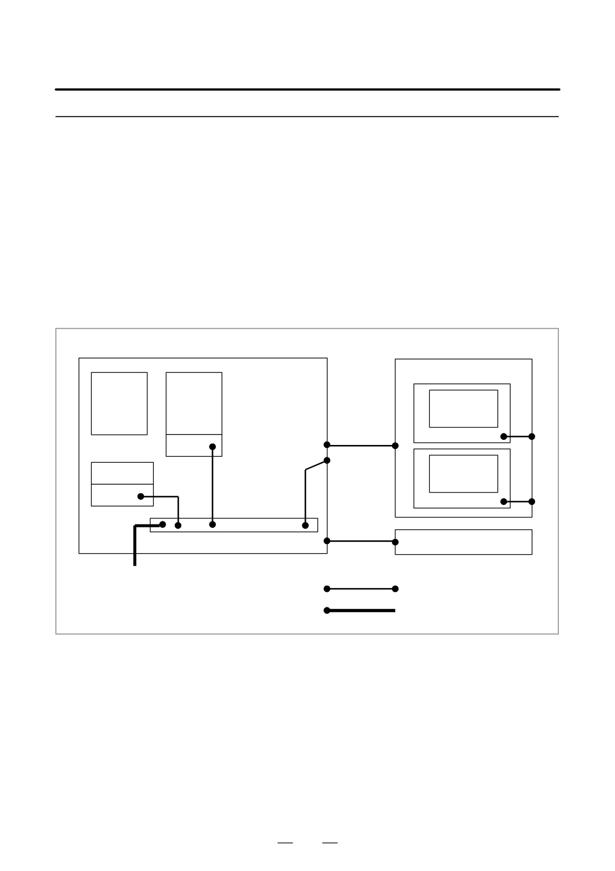
5.8.2
With a CNC machine tool, three ground systems are used.
Grounding
(1) Signal ground system (SG)
Signal ground (SG) provides a reference voltage (0 V) for the electric
signal system.
(2) Frame ground system (FG)
The purposes of frame ground (FG) are to ensure safety and to provide
shielding from external and internal noises. Specifically, the frames
of equipment, unit cases, panels, inter-unit interface cables, and so
forth are shielded.
(3) Protective earth (PE)
The protective earth (PE) is designed so that the protective grounds
provided between the units are connected to ground at one point from
a system point of view.
Pendant box
Distributed
αi amplifier
I/O
CNC
Frame
AC power
supply
Operator’s
24 V power
panel
supply
AC input
Frame
PE (Cabinet earth plate)
Machine cabinet
Connection line for grounding
Connection line for protective earth (PE)
Notes on ground system
D The grounding resistance of the protective earth (PE) must be 100
wiring
ohms or less (class-D grounding).
D The connection cable for the protective earth (PE) needs to have a
cross-sectional area sufficient for flowing an accidental current that
flows to the protective earth (PE) when an accident such as a short
circuit occurs.
(In general, a cross-sectional area equal to or greater
than that of the AC power line is required.)
D As a connection cable for the protective earth (PE), use a cable
integrated with an AC power line so that power is not fed when the
ground wire is disconnected.
379
5. MATTERS COMMON TO BOTH LCD-MOUNTED TYPE
AND STAND-ALONE TYPE i SERIES (HARDWARE)
B-63525EN/02
5.8.3
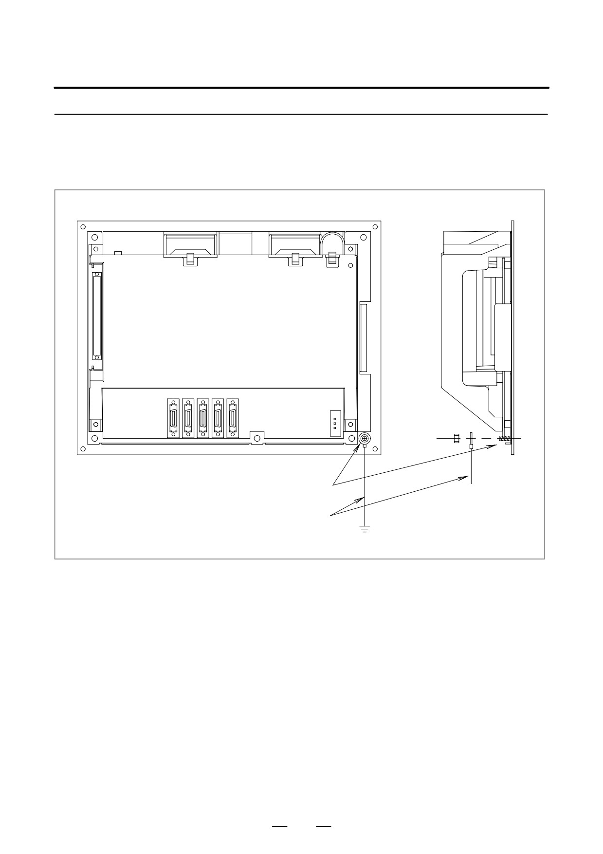
LCD-mounted type control unit
Signal Ground (SG)
Connection of Control
Unit
M4 stud
Ground cable
Wire of 2 mm2 or more
Connect the 0 V line inside the control unit to the ground plate of the
cabinet through the signal ground terminal (shown above).
For the ground terminal locations of other units, see the external unit
views in the appendix.
380
5. MATTERS COMMON TO BOTH LCD-MOUNTED TYPE
B-63525EN/02
AND STAND-ALONE TYPE i SERIES (HARDWARE)
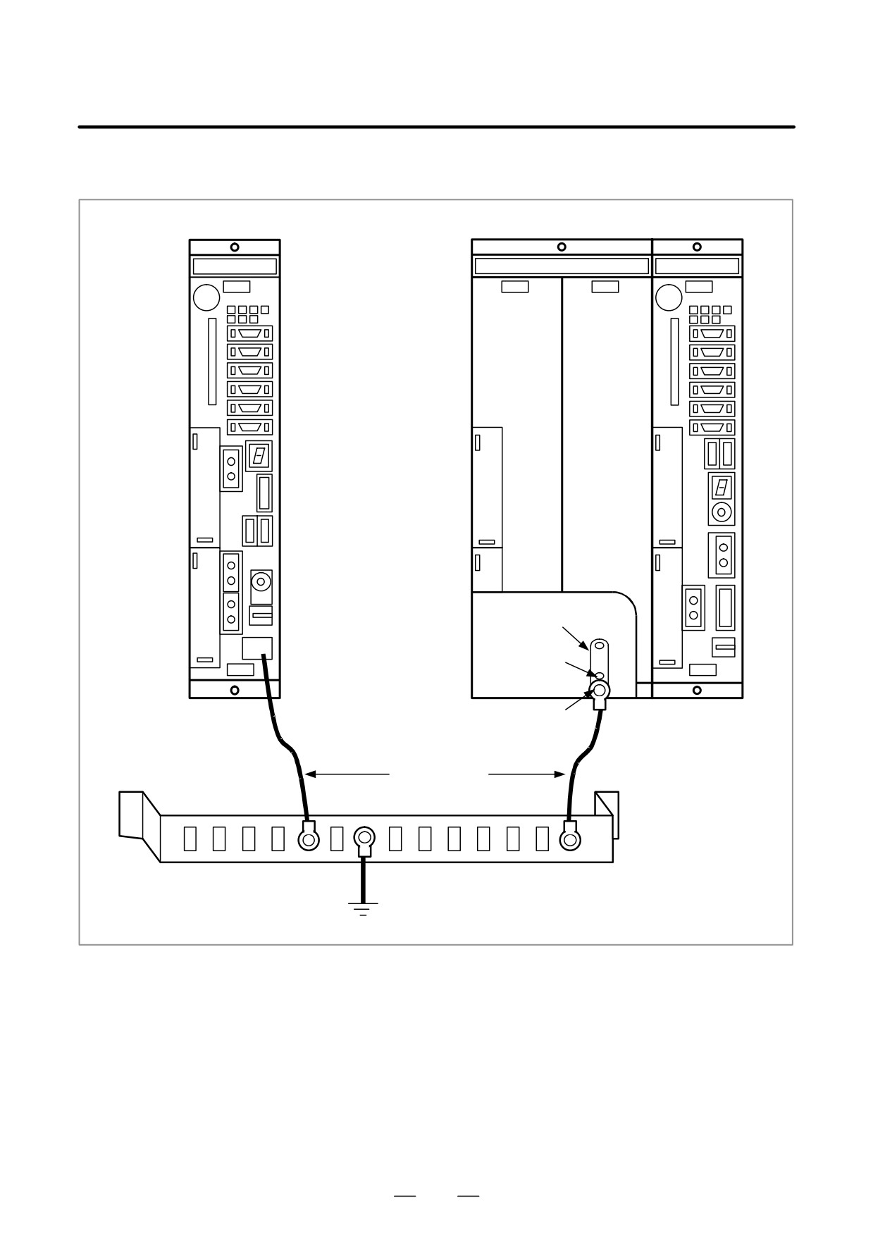
LCD stand-alone type control unit
For a one-slot rack
For a three-slot rack
Ground terminal
for signals
Ground terminal for signals
M4 (Screw hole)
(Faston terminal)
M3 (Screw hole)
Ground wire
2 mm2 or more
Ground plate
of the cabinet
PE
Connect the 0V line of the electronic circuitry in the control unit to the
ground plate of the cabinet via the ground terminal for signals.
Note that the method of ground connection varies, depending on whether
optional slots are provided.
Use a Faston terminal of the FANUC specification A02B-0166-K330.
See Appendix A.
381
5. MATTERS COMMON TO BOTH LCD-MOUNTED TYPE
AND STAND-ALONE TYPE i SERIES (HARDWARE)
B-63525EN/02
5.8.4
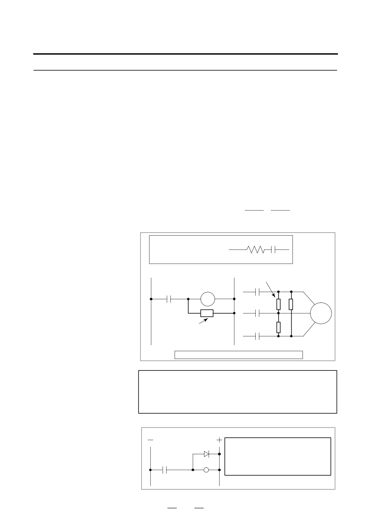
With a power magnetics cabinet, components such as an AC/DC solenoid
and AC/DC relay are used. When turned on and off, these components
Noise Suppressor
generate a high-energy pulse voltage due to coil inductance.
Such a pulse voltage is induced into cables, for example, and can interfere
with electric circuitry.
Notes on spark killer
D Select a CR-type spark killer (for use with AC circuitry) (A varistor
selection
has a function for clamping the peak voltage of a pulse voltage, but
cannot suppress a spike-like voltage. For this reason, the use of a
CR-type spark killer is recommended.)
D As the CR values of a spark killer, use the following with the
steady-state coil current (I (A)) and DC resistance used as references:
1) Resistance (R): Coil DC resistance
I2
I2
2) Electrostatic capacitance (C):
to
(mF)
10
20
I: Coil steady-state current (A)
R
C
Equivalent circuit of spark killer
Spark killer
AC relay
Motor
Spark killer
Install a spark killer near a motor, relay, and coil.
NOTE
Use a CR-type noise suppressor. A varistor has a function
for clamping the peak voltage of a pulse voltage, but cannot
suppress a spike-like voltage.
Diode (used for DC circuitry)
Diode
As a guideline, select a diode which has
a breakdown voltage about two times
greater than an applied voltage, and al-
DC relay
lows the flow of a current about two
times higher.
382
5. MATTERS COMMON TO BOTH LCD-MOUNTED TYPE
B-63525EN/02
AND STAND-ALONE TYPE i SERIES (HARDWARE)
5.8.5
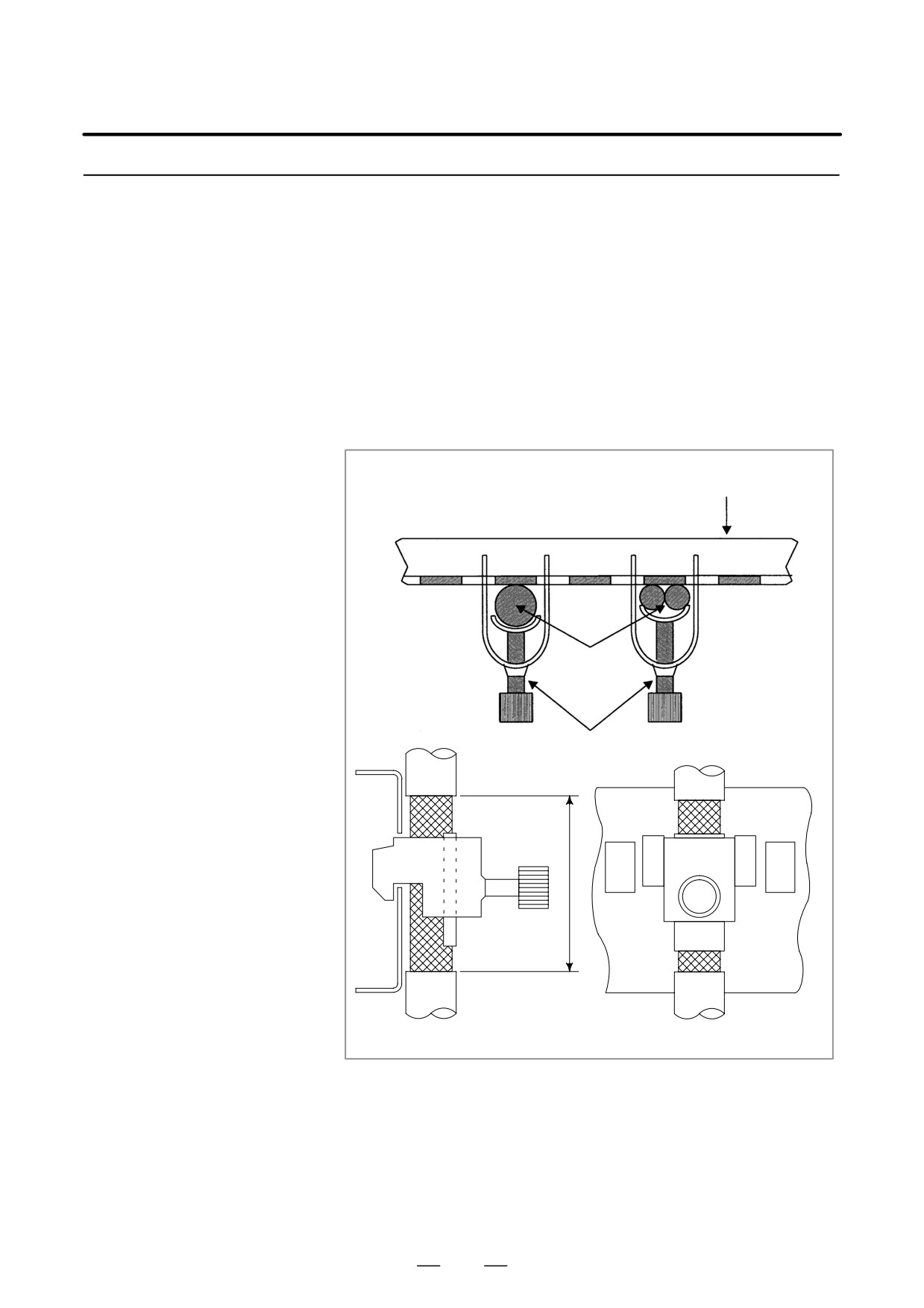
According to the figure below, clamp all cables that require shielding and
are run to the CNC, servo amplifier, spindle amplifier, and so forth. This
Cable Clamping and
clamping method not only secures cables, but also shields cables. Cable
Shielding
clamping and shielding are a key to stable system operation. Always
perform cable clamping and shielding according to the method described
here.
As shown below, peel off a part of the outer sheath of each cable so that
the shield cover is exposed, then press and retain the exposed part of the
shield against the ground plate with a clamp.
Install a ground plate manufactured by the machine tool builder, as shown
below.
Ground plate
Cable
Clamp
40mm to 80mm
Fig. 5.8.5 (a) Cable clamp (1)
383
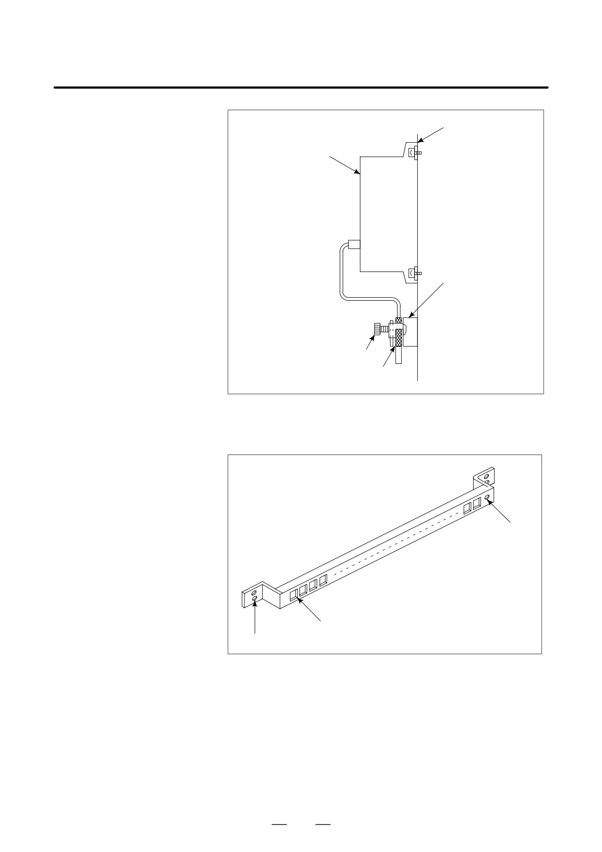
5. MATTERS COMMON TO BOTH LCD-MOUNTED TYPE
AND STAND-ALONE TYPE i SERIES (HARDWARE)
B-63525EN/02
Mounting plate of the machine
ÇÇ
ÇÇ
Control unit
ÇÇ
ÇÇ
ÇÇ
ÇÇ
ÇÇ
ÇÇ
ÇÇ
ÇÇ
Ground plate
ÇÇ
ÇÇ
ÇÇ
ÇÇ
Clamp
ÇÇ
Shield cover
ÇÇ
ÇÇ
Fig. 5.8.5 (b) Cable clamp (2)
Prepare a ground plate as shown below.
Ground terminal
(to be connected
to ground)
Clamp mounting hole
Mounting hole
Fig. 5.8.5 (c) Ground plate
For a ground plate, use an iron plate that is as thick as 2 mm or more and
is plated with nickel.
384
5. MATTERS COMMON TO BOTH LCD-MOUNTED TYPE
B-63525EN/02
AND STAND-ALONE TYPE i SERIES (HARDWARE)
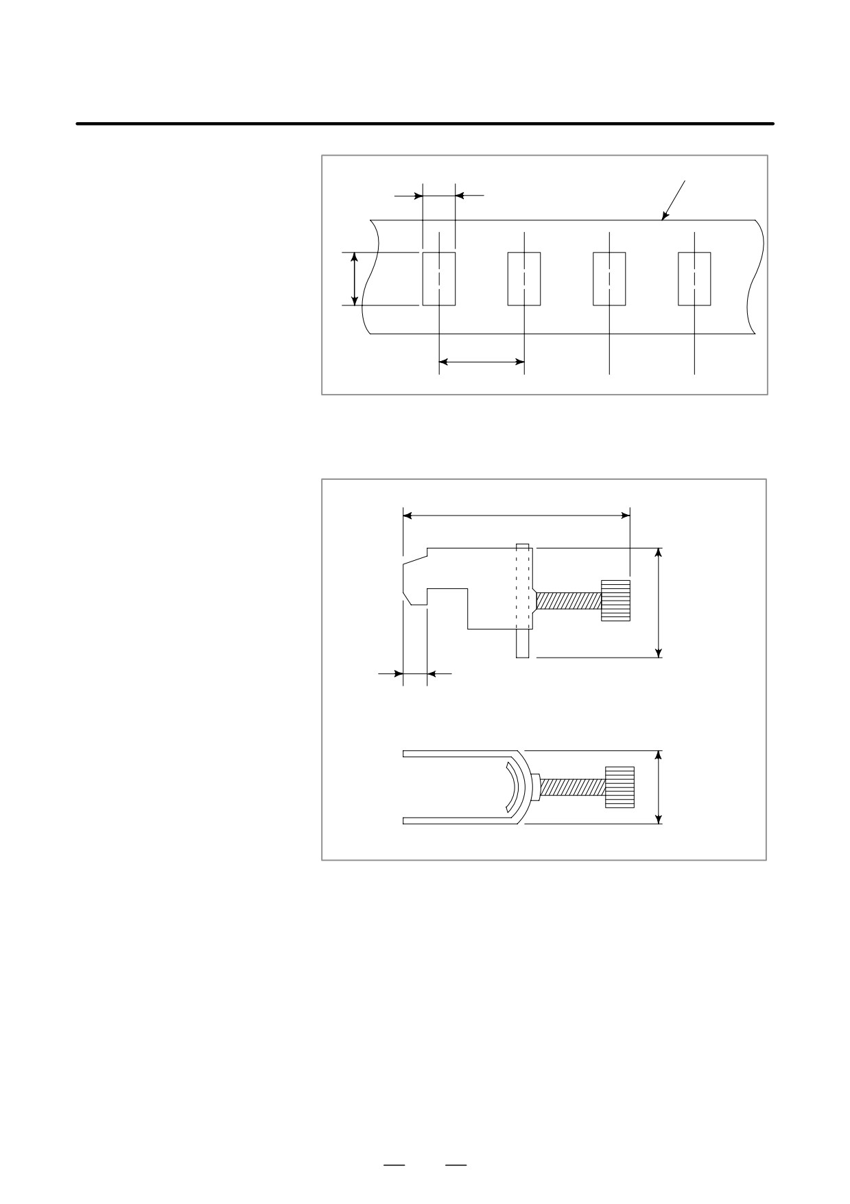
Ground plate
8mm
12mm
20mm
Fig. 5.8.5 (d) Ground plate hole diagram
Reference: Outline drawing of the clamp
55 mm maximum
28mm
6mm
17mm
Fig. 5.8.5 (e) Outline drawing of clamp
Ordering code of the clamp: A02B-0124-K001 (set of 8 clamps)
385
5. MATTERS COMMON TO BOTH LCD-MOUNTED TYPE
AND STAND-ALONE TYPE i SERIES (HARDWARE)
B-63525EN/02
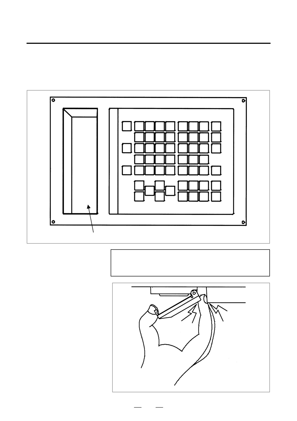
An MDI unit usable with a 12.1” LCD has a connector panel that allows
5.9
various interface connectors to be placed on the front. The connector
NOTES ON USING
panel has a cover. The cover is opened and closed when the connector
THE MDI UNIT
panel is used. Be careful not to have your fingers caught when
opening/closing (particularly opening) the cover.
MDI unit: A02B-0236-C321#xxx
Connector panel cover
CAUTION
Be careful not to have your fingers caught when
opening/closing the connector panel on the MDI unit.
Be careful not to have
your fingers caught.
386
5. MATTERS COMMON TO BOTH LCD-MOUNTED TYPE
B-63525EN/02
AND STAND-ALONE TYPE i SERIES (HARDWARE)
5.10
REPLACING THE
MAINTENANCE
PARTS OF CNC
DISPLAY UNIT FOR
PC FUNCTIONS AND
PANEL i
5.10.1
Replacing the Battery
D Ordering number
Item
Ordering number
Lithium battery
A02B-0200-K102
387
5. MATTERS COMMON TO BOTH LCD-MOUNTED TYPE
AND STAND-ALONE TYPE i SERIES (HARDWARE)
B-63525EN/02
D Replacing method
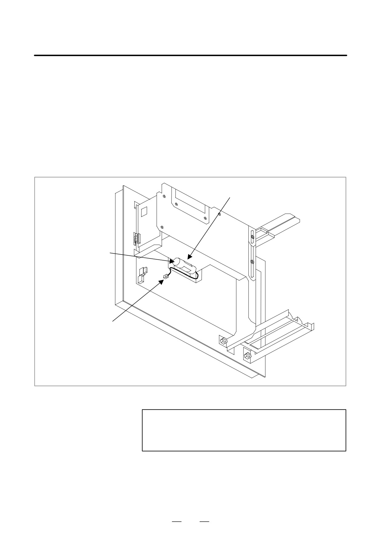
(1) After a lapse of five minutes from power up, power off the CNC
display unit with PC functions or the PANEL i. Then remove the CNC
display unit with PC functions or the PANEL i from the panel so that
it can be accessed from the back.
(2) Remove the connector for the lithium battery, then remove the battery
from the battery holder.
(3) Within five minutes, plug the connector (BAT1) for a new battery and
insert a new battery.
(4) Reinstall the CNC display unit with PC functions or the PANEL i.
(5) Turn on the power and make sure the BIOS parameter is not cleared
(no error occurs during startup).
Battery holder
Lithium battery
A02B-0200-K102
Connector
(BAT1)
Fig. 5.10.1 Replacing the battery
NOTE
It must not take more than five minutes from the time the old
battery is removed until the connector for the new battery is
plugged into the connector.
388
5. MATTERS COMMON TO BOTH LCD-MOUNTED TYPE
B-63525EN/02
AND STAND-ALONE TYPE i SERIES (HARDWARE)
When this procedure is used to replace the battery, normally the BIOS
settings are not cleared. However, in case the settings are cleared, the
following message appears during power up, the default BIOS settings
are loaded, and the unit automatically reboots.
251: System CMOS checksum bad - Default configuration used.
Therefore, check whether the default settings of the CNC display unit
with PC functions or the PANEL i are changed before maintenance. If the
settings are cleared to the defaults, restore the BIOS settings.
5.10.2
Replacing the Fuse
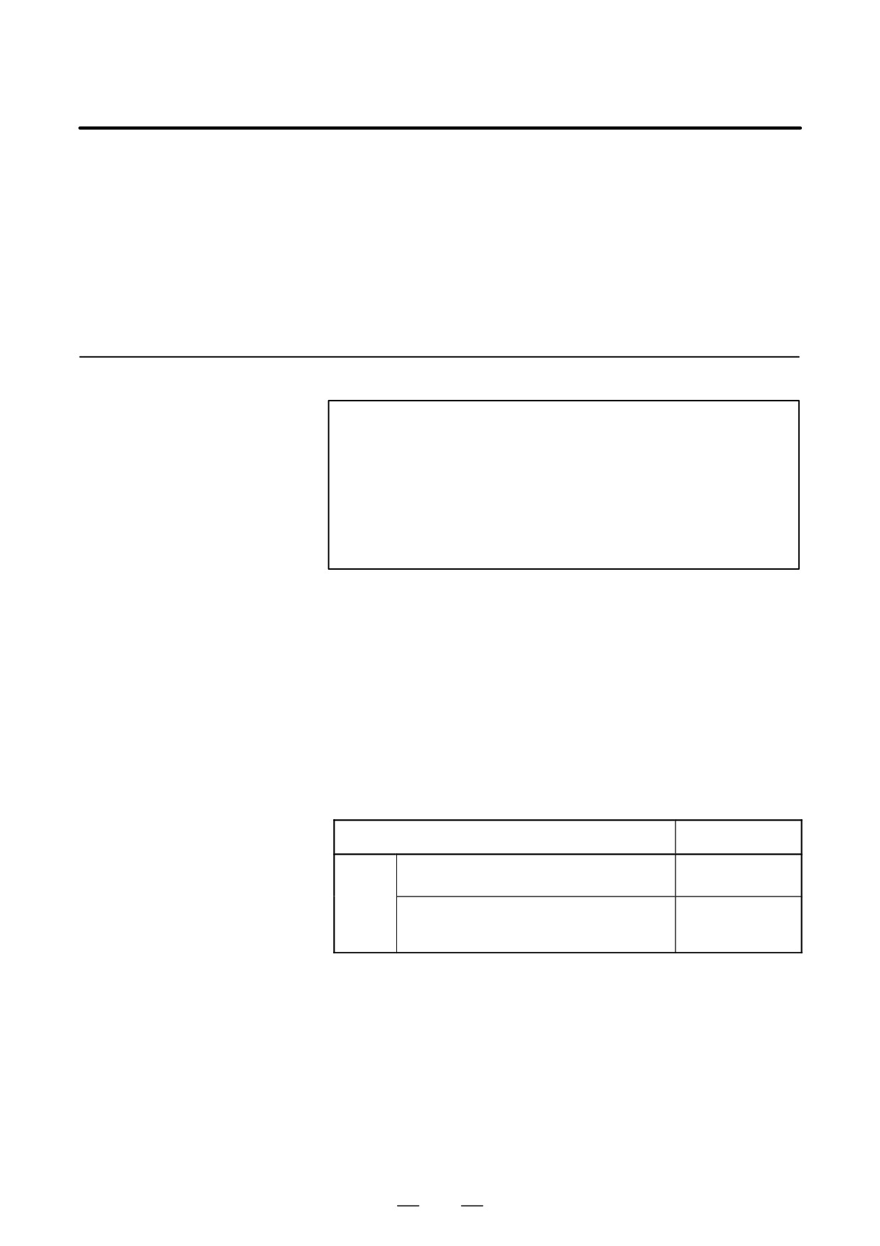
WARNING
Before replacing the fuse, eliminate the cause by which the
fuse blew.
Therefore, only those personnel who were well trained for
maintenance and safety can perform the replacement.
When replacing the fuse with the cabinet open, be careful
not to touch the part containing high-voltage circuits.
Otherwise, you receive an electric shock.
A fuse blows when there is a short circuit in the CNC display unit with
PC functions or the PANEL i. When the fuse blows, check the following
points.
S A conductive part touches the main printed circuit board.
S A PCI extension board failed or is incorrectly inserted.
S A cable is incorrectly connected.
When the fuse blows, the system may suffer damage. Before turning on
the power again, make visual and smell inspection to check the system for
an abnormality and replace the failed parts if any.
D Ordering number
Item
Ordering number
Fuse
For A08B-0082-B001 to -B004, -B011 to -B014,
A02B-0236-K101
–B031 to -B038, A13B-0193-B031 to -B038
A08B-0082-B021 to -B024, -B041 to -B048,
A08B-0082-K001
-B051 to -B058, A13B-0193-B041 to -B048,
–B051 to -B058
389
5. MATTERS COMMON TO BOTH LCD-MOUNTED TYPE
AND STAND-ALONE TYPE i SERIES (HARDWARE)
B-63525EN/02
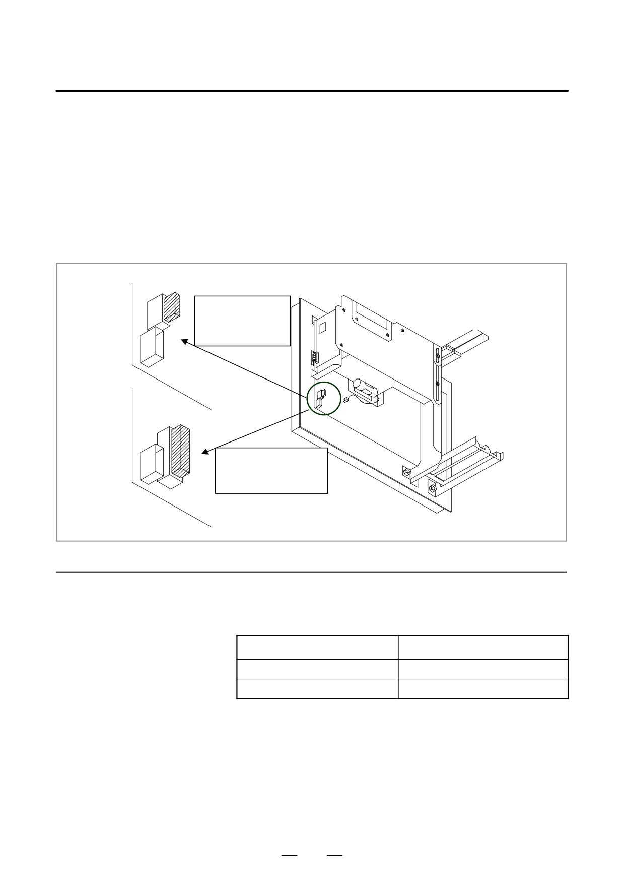
D Replacing method
(1) Make sure the CNC display unit with PC functions or the PANEL i is
powered off.
(2) Remove the CNC display unit with PC functions or the PANEL i from
the panel so that it can be accessed from the back.
(3) Remove the old fuse from the socket, then securely insert a new one
into it.
(4) Reinstall the CNC display unit with PC functions or the PANEL i.
(5) Turn on the power and verify that the CNC display unit with PC
functions or the PANEL i starts up normally.
Fuse : A02B-0236-K101
For A08B-0082-B001
to -B004, -B011 to -
B014, -B031 to B-038,
A13B-0193-B031to
B-038
A08B-0082-B021 to -B024,
-B041 to -B048, -B051 to
-B058, A13B-0193-B041 to
-B048, -B051 to -B058
Fuse : A08B-0082-K001
5.10.3
Replacing the Fan
D Ordering number
Item
Ordering number
Fan for main body
A08B-0082-K010
Fan for HDD
A13B-0178-K001
390
5. MATTERS COMMON TO BOTH LCD-MOUNTED TYPE
B-63525EN/02
AND STAND-ALONE TYPE i SERIES (HARDWARE)
D Replacing the fan for
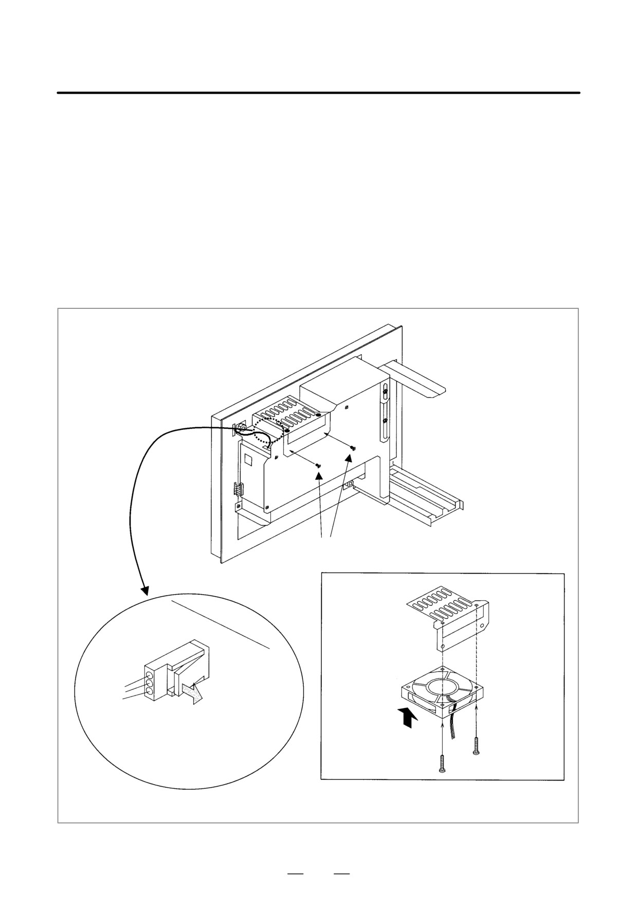
(1) Make sure the CNC display unit with PC functions or the PANEL i is
main body
powered off.
(2) Loosen the two screws (A), then remove the fan retaining metal sheet.
(3) Remove the fan connector (CN6). Since the connector is fixed with
a latch, pull out the connector while opening the latch with a flatblade
screwdriver, as shown below.
(4) Loosen the two screws (B), then replace the fan.
(5) Install a new fan in the unit by reversing the removal procedure. At
this time, be sure to install the fan in the correct direction.
Two screws (A)
Fan retaining
metal sheet
CN6 FAN
Fan
A08B-0082-K010
Be sure to install
the fan in the cor-
rect direction.
For A08B-0082-B001 to -B004, -B011 to -B014,
-B021 to -B024
391