FANUC Series 16i/160i/160is-MODEL B, Series 18i/180i/180is-MODEL B, Series 21i/210i/210is-MODEL B. MAINTENANCE MANAUL - page 13
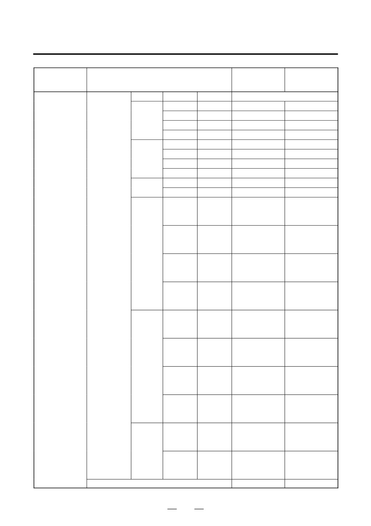
4. STAND-ALONE TYPE i SERIES HARDWARE
B-63525EN/02
Drawing number
Main drawing
Type
Item
of unit for
number
maintenance
(Basic unit)
Printed circuit board
Base unit
LCD
Soft key
Touch panel
for CNC display unit
10.4” LCD
A08B-0082-D001
A08B-0082-B001
with PC functions and
PANEL i
Ę
A08B-0082-D002
A08B-0082-B002
Ę
A08B-0082-D003
A08B-0082-B003
Ę
Ę
A08B-0082-D004
A08B-0082-B004
12.1”LCD
A08B-0082-D011
A08B-0082-B011
Ę
A08B-0082-D012
A08B-0082-B012
Ę
A08B-0082-D013
A08B-0082-B013
Ę
Ę
A08B-0082-D014
A08B-0082-B014
15.0”LCD
A08B-0082-D021
A08B-0082-B021
Ę
A08B-0082-D023
A08B-0082-B023
10.4”LCD
A08B-0082-D031
A08B-0082-B031
A08B-0082-B035
A13B-0193-B031
A13B-0193-B035
Ę
A08B-0082-D032
A08B-0082-B032
A08B-0082-B036
A13B-0193-B032
A13B-0193-B036
Ę
A08B-0082-D033
A08B-0082-B033
A08B-0082-B037
A13B-0193-B033
A13B-0193-B037
Ę
Ę
A08B-0082-D034
A08B-0082-B034
A08B-0082-B038
A13B-0193-B034
A13B-0193-B038
12.1”LCD
A08B-0082-D041
A08B-0082-B041
A08B-0082-B045
A13B-0193-B041
A13B-0193-B045
Ę
A08B-0082-D042
A08B-0082-B042
A08B-0082-B046
A13B-0193-B042
A13B-0193-B046
Ę
A08B-0082-D043
A08B-0082-B043
A08B-0082-B047
A13B-0193-B043
A13B-0193-B047
Ę
Ę
A08B-0082-D044
A08B-0082-B044
A08B-0082-B048
A13B-0193-B044
A13B-0193-B048
15.0”LCD
A08B-0082-D051
A08B-0082-B051
A08B-0082-B055
A13B-0193-B051
A13B-0193-B055
Ę
A08B-0082-D053
A08B-0082-B053
A08B-0082-B057
A13B-0193-B053
A13B-0193-B057
3.5” HDD unit (including the FAN for HDD)
A08B-0082-C100
A08B-0082-H100
332
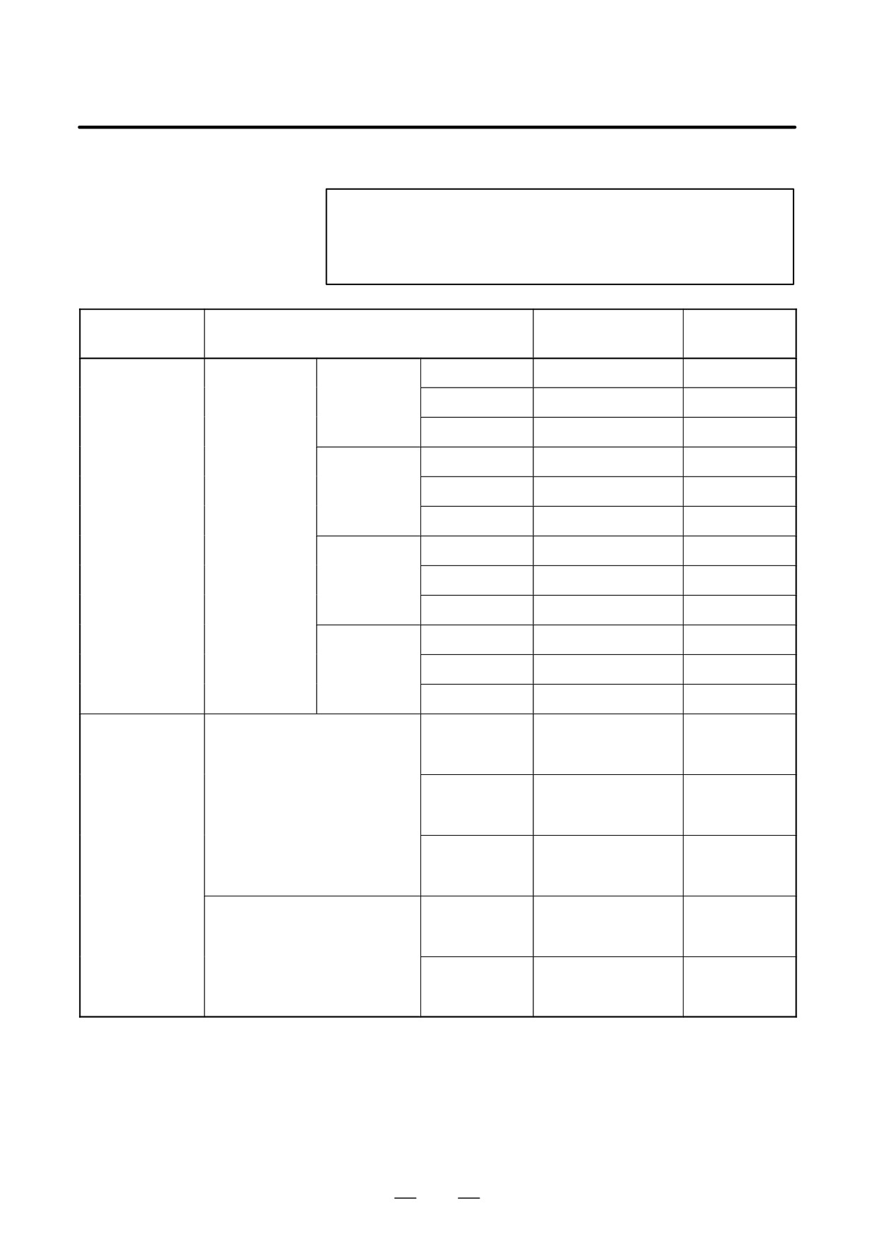
4. STAND-ALONE TYPE i SERIES HARDWARE
B-63525EN/02
Ę: Provided
: None
NOTE
The base unit for maintenance consists of the components
of the basic unit from which the main printed circuit board
and its retaining screws are excluded.
Drawing number
Main drawing
Type
Item
for maintenance
number
Printed circuit board
PC card
MMX-
For 10.4” LCD
A08B-0082-H500#6141
A08B-0082-H010
for PC function of
Pentium 233MHz
CNC display unit with
For 12.1” LCD
A08B-0082-H500#6142
A08B-0082-H011
PC functions and
PANEL i
For 15.0” LCD
A08B-0082-H500#6143
A08B-0082-H012
PentiumII
For 10.4” LCD
A08B-0082-H511#6138
A08B-0082-H020
333MHz
For 12.1” LCD
A08B-0082-H511#6139
A08B-0082-H021
For 15.0” LCD
A08B-0082-H511#6140
A08B-0082-H022
Celeron
For 10.4” LCD
A08B-0082-H512#613D
A08B-0082-H040
400MHz
For 12.1” LCD
A08B-0082-H512#613E
A08B-0082-H041
For 15.0” LCD
A08B-0082-H512#613F
A08B-0082-H042
PentiumIII
For 10.4” LCD
A08B-0082-H520#613G
A08B-0082-H050
500MHz
For 12.1” LCD
A08B-0082-H520#613H
A08B-0082-H051
For 15.0” LCD
A08B-0082-H520#613J
A08B-0082-H052
Memory
Main memory
DRAM 32MB (*)
A76L-0500-0013
A08B-0082-H001
(For MMX-Pentium 233MHz and
(Specification:TOSHIBA
PentiumII 333MHz)
THL64V4075BTG-5S)
DRAM 64MB
A76L-0500-0014
A08B-0082-H002
(Specification: TOSHIBA
THL64V8015BTG-5S)
DRAM 128MB
A76L-0500-0017
A08B-0082-H003
(Specification: PFU
PD-2261ADS)
Main memory
SDRAM 64M
A76L-0500-0018
A08B-0082-H004
(For Celeron 400MHz and PentiumIII
(Specification: PFU
500MHz)
PD-2261ACS)
SDRAM 128M
A76L-0500-0019
A08B-0082-H005
(Specification: PFU
PD-2261ADSA)
*: DRAM 32 MB can be used only for the MMX-Pentium 233MHz.
333
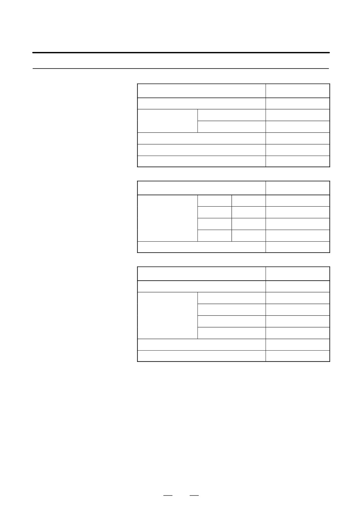
4. STAND-ALONE TYPE i SERIES HARDWARE
B-63525EN/02
4.5.6
Printed circuit boards
CNC Display Unit for is
Name
Drawing number
series CNC
Motherboard
A20B-8100-0800
CE card
CE card 1
A20B-3300-0330
CE card 2
A20B-3300-0320
Power supply unit
A20B-8100-0720
Printed circuit board of Inverter
A20B-8001-0920
Printed circuit board of backup unit
A20B-2100-0820
Units
Name
Drawing number
10.4” LCD unit
Soft keys
Touch panel
Ę
A02B-0281-D500
Ę
A02B-0281-D501
Ę
Ę
A02B-0281-D508
FA full-keyboard
A02B-0281-C130#E
Others
Name
Drawing number
Case
A02B-0236-D100#0C
Compact flash card
32MB
A87L-0001-0173#32MBA
48MB
A87L-0001-0173#48MBA
64MB
A87L-0001-0173#64MB
96MB
A87L-0001-0173#96MB
Cable for backup unit
A02B-0281-K801
Cable for FA full-keyboard
A02B-0281-K802
334
4. STAND-ALONE TYPE i SERIES HARDWARE
B-63525EN/02
4.6
MOUNTING AND
REMOVING AN
OPTION BOARD
WARNING
The replacement described here should be performed by a
person fully trained in maintenance and safety. If the
cabinet is opened to replace the option board, take extreme
care not to touch any high-voltage area (marked with
and covered by a shock prevention cover). If the area is
uncovered, direct contact with this area will result in an
electric shock.
NOTE
Before starting the replacement, take a back-up copy of the
contents
(parameters, programs, etc.) of the SRAM
memory of the CNC. The backup copy can be used in case
the contents of the SRAM memory are lost during the
replacement.
4.6.1
Mounting and
Removing the Main
CPU Board and a
Full-Size Option Board
4.6.1.1
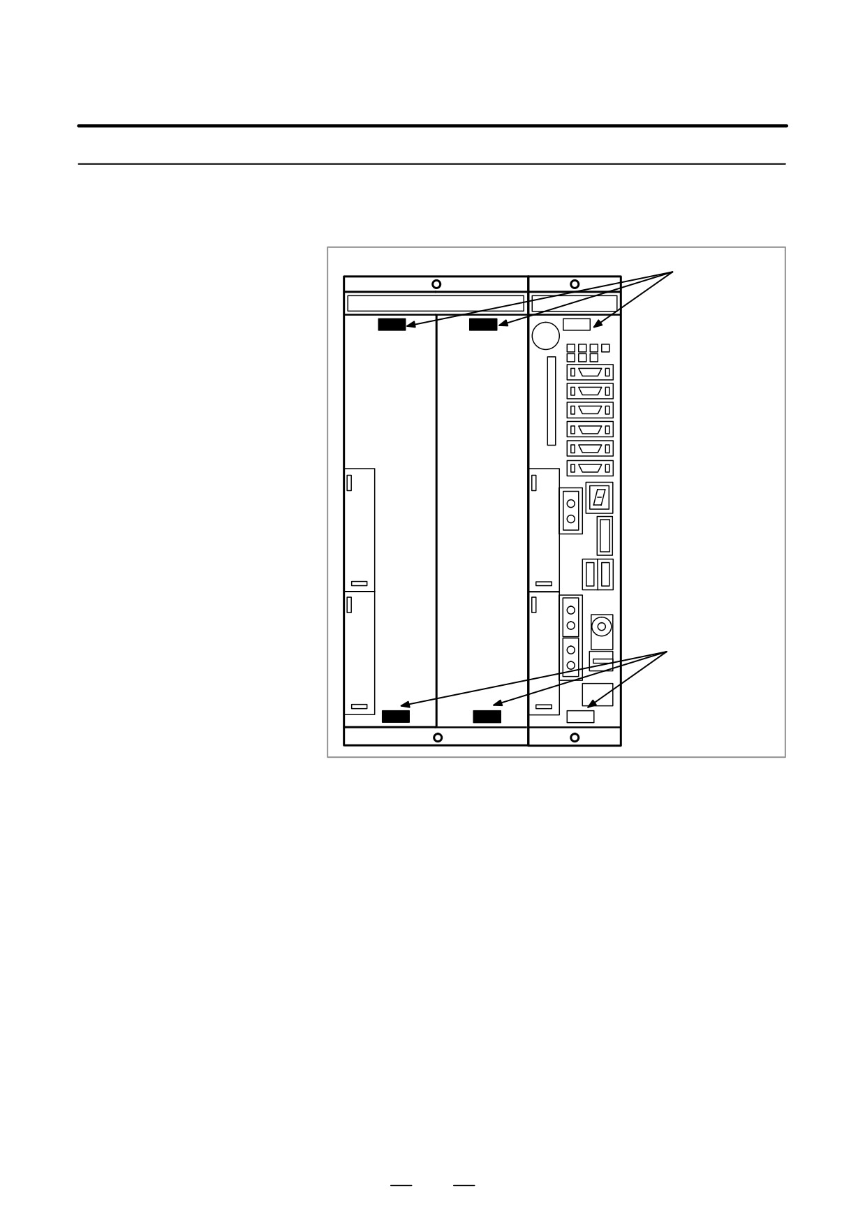
(1) Remove cables other than the battery cable.
(The battery cable is
connected only to the main CPU board.)
Removing the board
(2) Hold handles A and B.
(3) Pushing down the hook of handle A and pushing up the hook of handle
B, pull out the printed circuit board.
NOTE
1
The battery is mounted on the face place of the main CPU
board. The battery is pulled out together with the main CPU
board.
2
The main CPU board or a full-size option board can be
removed without removing mini-slot option boards.
(If a
cable connected to a mini-slot option board obstructs the
removal, the cable must be removed.)
335
4. STAND-ALONE TYPE i SERIES HARDWARE
B-63525EN/02
4.6.1.2
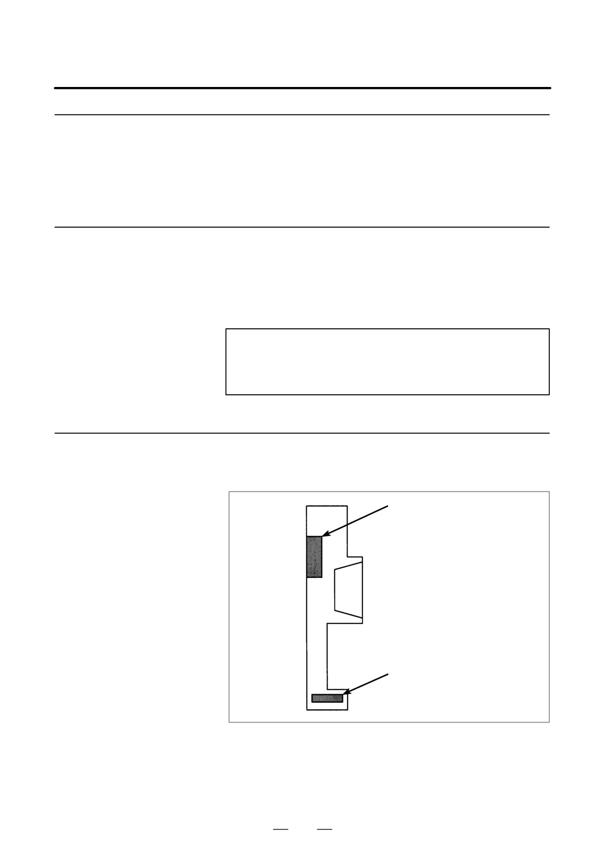
(1) Holding handles A and B, insert the board into the cabinet until the
connector on the back panel is connected.
Mounting the board
(2) Connect the removed cables to correct positions.
Handle A
With a hook on
the top side
Handle B
With a hook on
the bottom side
336
4. STAND-ALONE TYPE i SERIES HARDWARE
B-63525EN/02
4.6.2
Mounting and
Removing a Mini-Slot
Option Board (Except
DeviceNet Board)
(1)Remove cables connected to the target mini-slot option board.
4.6.2.1
Remove other cables that would obstruct the removal of the mini-slot
Removing the board
option board.
(2) Hold handles C and D.
(3) Pushing the latch of handle C to the right, pull out the printed circuit
board.
NOTE
The mini-slot option board can be removed without
removing the main CPU option board or full-size option
board.
4.6.2.2
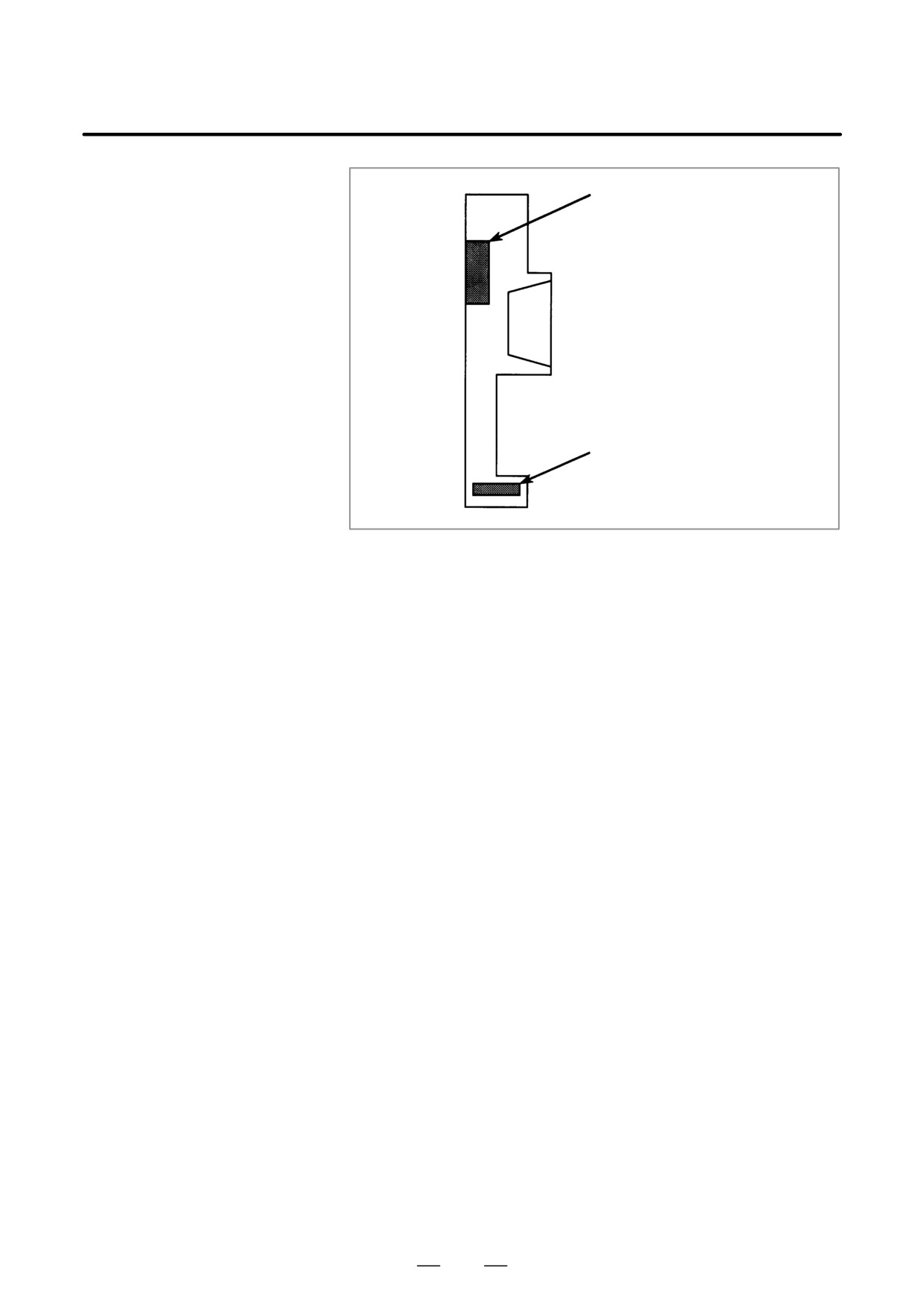
(1) Holding handles C and D, insert the board into the cabinet until the
connector on the back panel is connected.
Mounting the board
(2) Connect the removed cables to correct positions.
Handle C
With a hook on
the left side
Handle D
337
4. STAND-ALONE TYPE i SERIES HARDWARE
B-63525EN/02
4.6.3
Mounting and
Removing the
DeviceNet Board
4.6.3.1
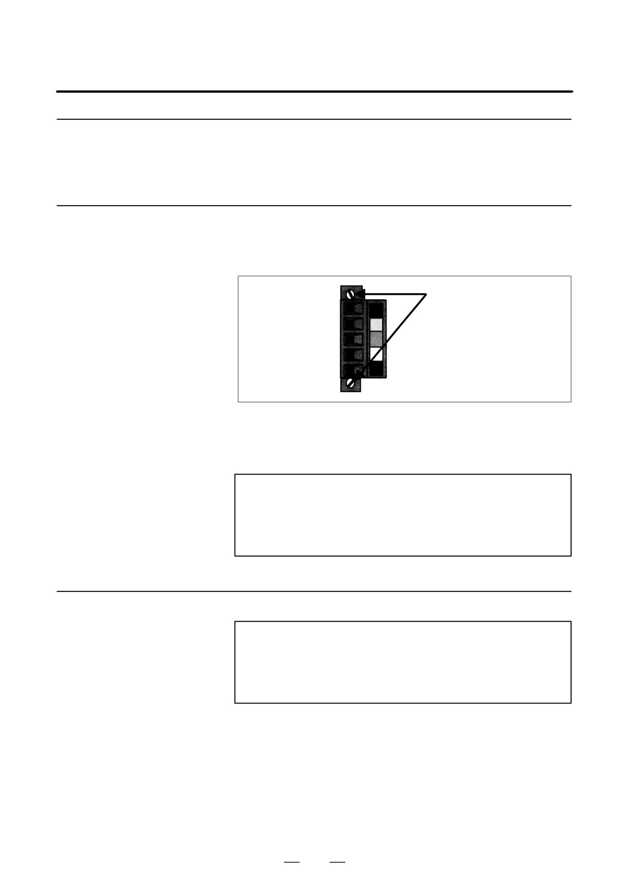
(1) Remove the terminal block from the connector on the DeviceNet
board. The terminal block can be pulled out after the screws on both
Removing the board
sides are loosened. The terminal block can be removed with cables
connected.
Screw
(2) Remove the main CPU board. The main CPU board can be removed
after the terminal block of the DeviceNet connector is removed.
(3) Hold handles C and D of the DeviceNet board. Pushing the latch of
handle C to the right, pull out the board.
NOTE
The DeviceNet board can be removed after the main CPU
board is removed. If an attempt is made to pull out the
DeviceNet board without removing the main CPU board, the
printed board may be damaged.
4.6.3.2
(1) Before mounting the DeviceNet board, remove the main CPU board.
Mounting the board
NOTE
The DeviceNet board can be mounted after the main CPU
board is removed. If an attempt is made to mount the
DeviceNet board without removing the main CPU board, the
printed circuit may be damaged.
(2) Remove the terminal block from the connector on the DeviceNet
board. (See the removal procedure described above.)
(3) Mount the DeviceNet board in the cabinet without the main CPU
board. Holding handles C and D, insert the board into the cabinet until
the connector on the back panel is connected.
(4) After mounting the DeviceNet board, mount the main CPU board.
(5) Mount the terminal block removed in (2) to the connector. Securely
tighten the screws.
338
4. STAND-ALONE TYPE i SERIES HARDWARE
B-63525EN/02
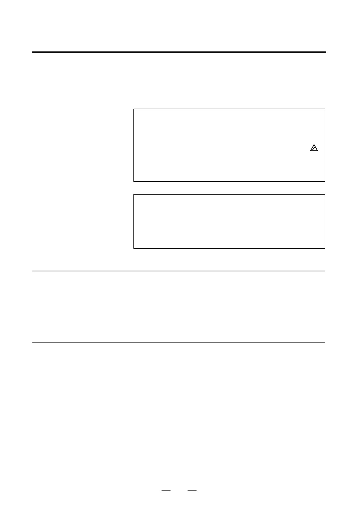
Handle C
With a hook on the
left side
Handle D
339
4. STAND-ALONE TYPE i SERIES HARDWARE
B-63525EN/02
4.7
MOUNTING AND
REMOVING THE
BACK PANEL
WARNING
The replacement described here should be performed by a
person fully trained in maintenance and safety. If the
cabinet is opened to replace the back panel, take extreme
care not to touch any high-voltage area (marked with
and covered by a shock prevention cover). If the area is
uncovered, direct contact with this area will result in an
electric shock.
NOTE
Before starting the replacement, take a back-up copy of the
contents
(parameters, programs, etc.) of the SRAM
memory of the CNC. The backup copy can be used in case
the contents of the SRAM memory are lost during the
replacement.
4.7.1
(1) Remove the main CPU board and all option boards, following the
steps described in Section 3.6.
Removing the Panel
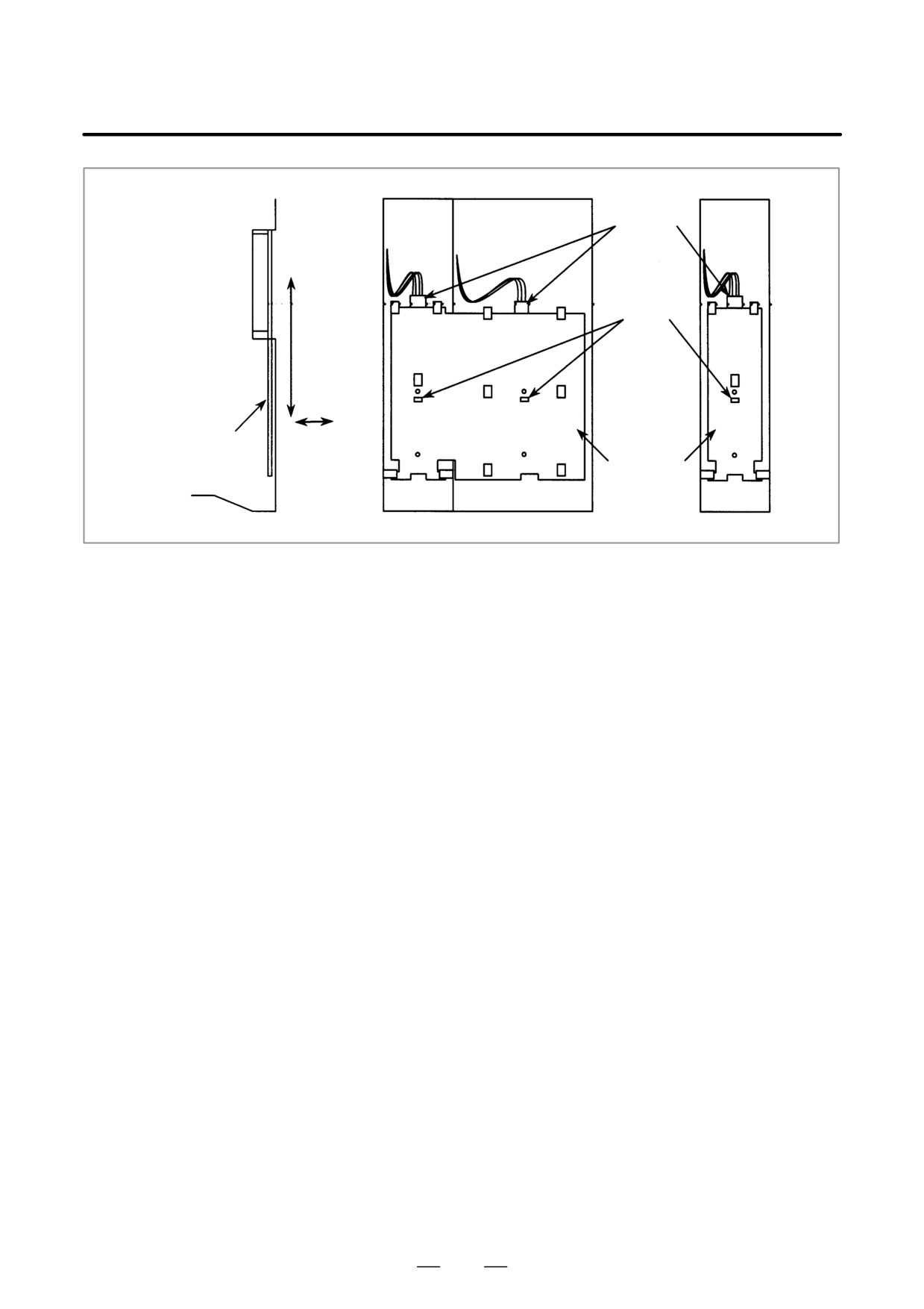
(2) Remove the connector of the fan connected to the back panel.
(3) Push down the latch securing the back panel until the latch is
disengaged.
(4) Pull down and detach the back panel to the rear.
4.7.2
(1) Aligning the positioning hole of the back panel with the positioning
pin, fit the back panel on from the rear.
Mounting the Back
(2) Pull up the back panel until the latch is engaged.
Panel
(3) Connect the fan connector to the back panel.
(4) Mount the main CPU board and option boards, following the steps
described in Section 3.6.
340
4. STAND-ALONE TYPE i SERIES HARDWARE
B-63525EN/02
Fan
connector
Latch
Back panel
Back panel
341
4. STAND-ALONE TYPE i SERIES HARDWARE
B-63525EN/02
4.8
REPLACING THE
WARNING
FUSE OF THE
Before starting the replacement of a fuse, remove the cause
CONTROL UNIT
of the fuse burn-out.
Accordingly, the replacement should be performed by a
person fully trained in maintenance and safety. If the
cabinet is opened to replace the fuse, take extreme care not
to touch any high-voltage area
(marked with
and
covered by a shock prevention cover). If the area is
uncovered, direct contact with this area will result in an
electric shock.
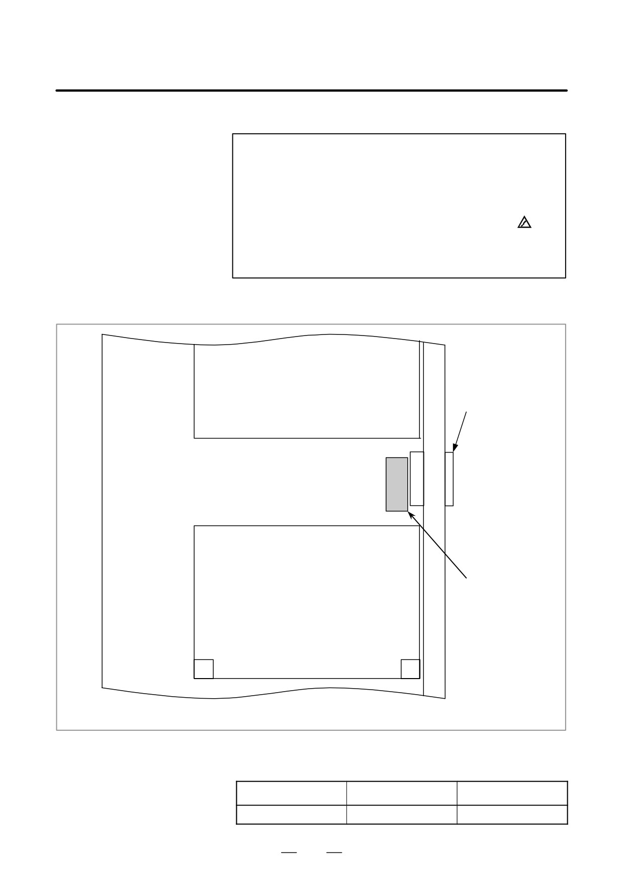
D Mounting position of the
The fuse of the control unit is mounted on the main CPU board.
fuse of the control unit
Display control card
CP1, CP2
Fuse
Axis control card
Main CPU board
D Ordering information of
the fuse
Ordering information
Rating
Individual information
A02B-0265-K100
7.5A
A60L-0001-0046#7.5
342
4. STAND-ALONE TYPE i SERIES HARDWARE
B-63525EN/02
Part programs, offset data, and system parameters are stored in CMOS
4.9
memory in the control unit. The power to the CMOS memory is backed
REPLACING THE
up by a lithium battery mounted on the front panel of the control unit. The
BATTERY
above data is not lost even when the main battery goes dead. The backup
battery is mounted on the control unit at shipping. This battery can
maintain the contents of memory for about a year.
When the voltage of the battery becomes low, alarm message “BAT”
blinks on the display and the battery alarm signal is output to the PMC.
When this alarm is displayed, replace the battery as soon as possible. In
general, the battery can be replaced within two or three weeks, however,
this depends on the system configuration.
If the voltage of the battery becomes any lower, memory can no longer
be backed up. Turning on the power to the control unit in this state causes
system alarm 910 (SRAM parity alarm) or 935 (SRAM ECC error) to
occur because the contents of memory are lost. Clear the entire memory
and reenter data after replacing the battery.
The following two kinds of batteries can be used.
D Lithium battery built into the CNC control unit.
D Two alkaline dry cells (size D) in the external battery case.
NOTE
A lithium battery is installed as standard at the factory.
343
4. STAND-ALONE TYPE i SERIES HARDWARE
B-63525EN/02
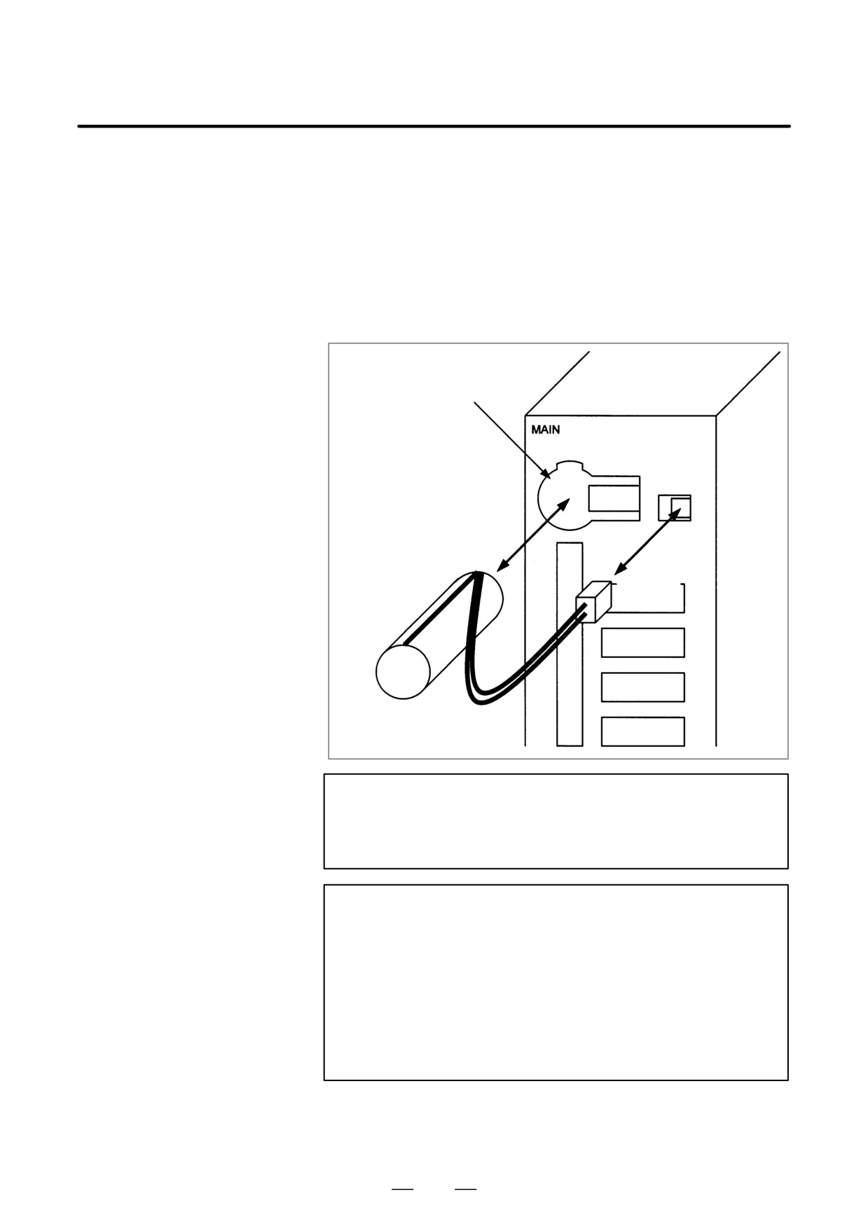
D Replacing the battery
If a lithium battery is used, have A02B-0200-K102 (FANUC internal
code: A98L-0031-0012) handy.
(1) Turn the CNC on. About 30 seconds later, turn the CNC off.
(2) Remove the battery from the top area of the CNC unit.
Disconnect the connector first. Then, remove the battery from the
battery case.
The battery case is provided in the top area of the face plate of the main
CPU board.
(3) Replace the battery, then connect the connector.
Battery case
Lithium battery
A02B-0200-K102
Connector
WARNING
The incorrect mounting of the battery may cause an
explosion. Avoid using any battery other than the one
specified here (A02B-0200-K102).
CAUTION
Complete steps (1) to (3) within 30 minutes.
If the battery is left removed for a long time, the memory
would lose the contents.
If there is a danger that the replacement cannot be
completed within 30 minutes, save the whole contents of the
CMOS memory to a memory card. The contents of the
memory can be easily restored with the memory card in
case the memory loses the contents.
Discard the dead battery, observing appropriate municipal rules and
regulations. When discarding the battery, insulate the terminal with a tape
so that no short-circuit would occur.
344
4. STAND-ALONE TYPE i SERIES HARDWARE
B-63525EN/02
When using commercial
D-size alkaline dry cells
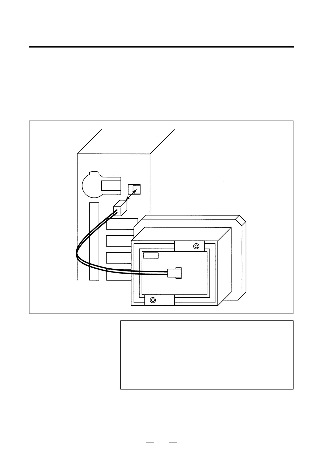
D General method
Use the connector connected to the lithium battery for an external battery.
Following the battery replacement procedure described above, replace the
standard lithium battery with an external battery in a battery case
(A02B-0236-C281).
CAUTION
1
Place the battery case
(A02B-0236-C281) in such a
position that the battery can be replaced even while the
control unit is active.
2
The connector of the battery cable uses a simple lock
system. Fix the cable within an area of 50 cm from the
connector, removing tension on the cable. This is required
to prevent the connector from coming off because of the
weight of the cable or tension on the cable.
345
4. STAND-ALONE TYPE i SERIES HARDWARE
B-63525EN/02
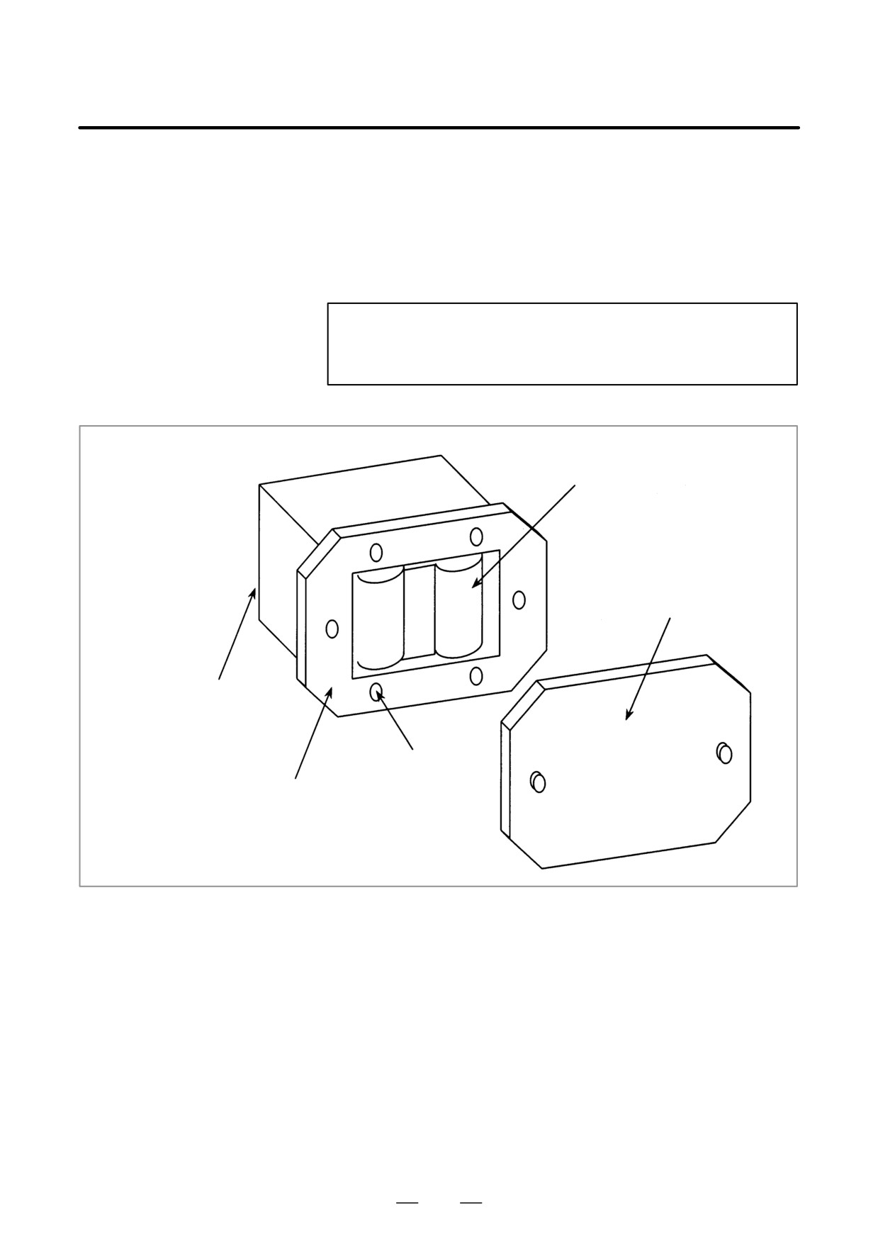
D Replacing the battery
(1) Have commercial D-size alkaline dry cells handy.
(2) Turn the CNC on.
(3) Remove the lid from the battery case.
(4) Replace the old dry cells with new ones. Mount the dry cells in a
correct orientation.
(5) Replace the lid on the battery case.
CAUTION
In the power-off state, the battery should be replaced as in
the case of the lithium battery, which is descried above.
2 dry cells
Lid
Connection terminal
on the back
4 mounting holes
Case
346
4. STAND-ALONE TYPE i SERIES HARDWARE
B-63525EN/02
4.10
REPLACING A FAN
UNIT
WARNING
If the cabinet is opened to replace a fan unit, take extreme
care not to touch any high-voltage area (marked with
and covered by a shock prevention cover). If the area is
uncovered, direct contact with this area will result in an
electric shock.
D Ordering information of
fan units
Ordering information
Quantity
For 1-slot cabinet
A02B-0265-C101
1
For 2-slot cabinet
A02B-0260-C021
1
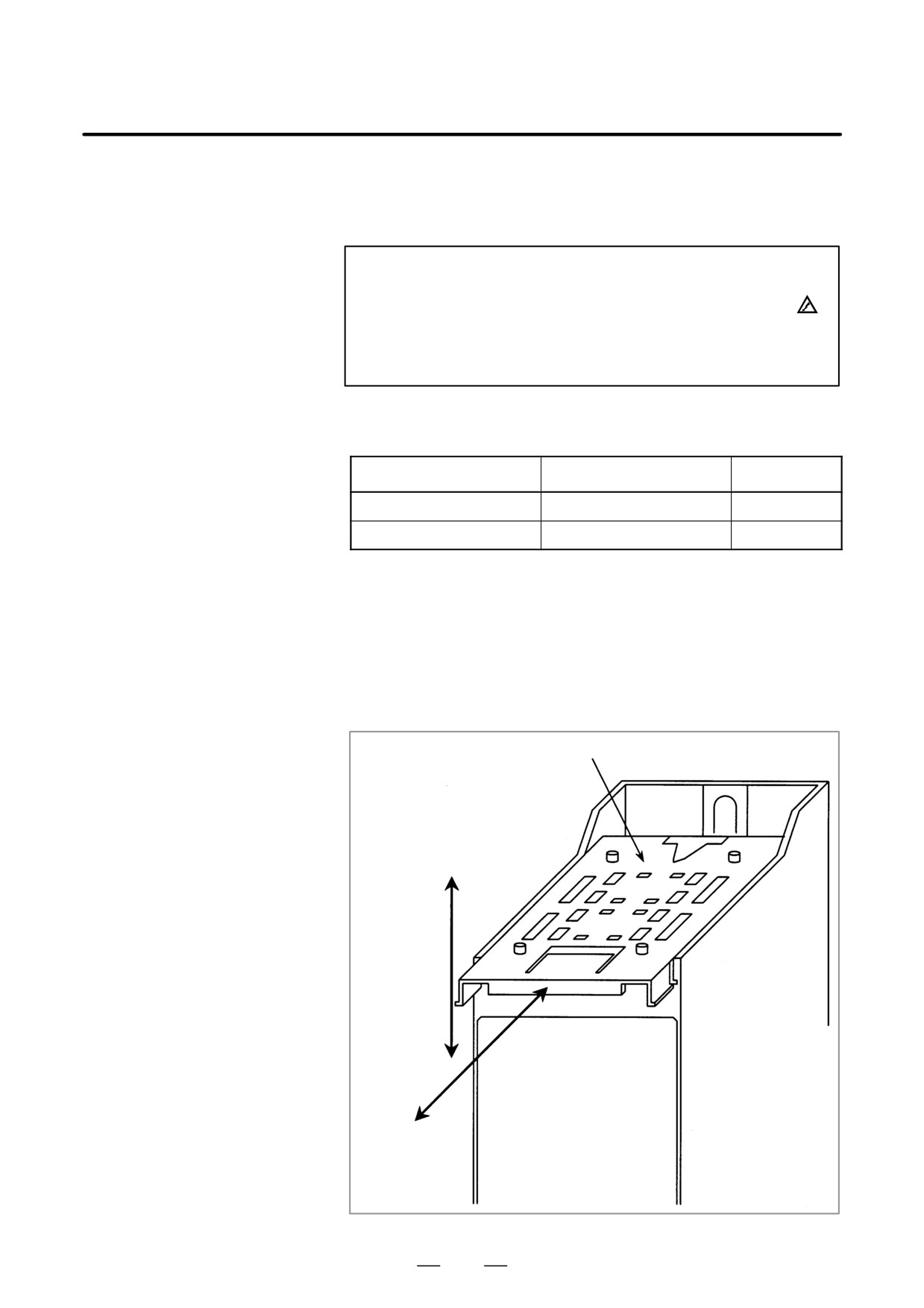
D Replacing a fan unit
(1) Before starting the replacement of a fan unit, turn the CNC off.
(2) Pull the fan unit to be replaced.
(3) Lift the pulled fan unit until the fan unit is detached from the cabinet.
(4) Place a new fan unit on the cabinet.
(5) Push the new unit as far as it goes. When a click is heard, the unit is
connected to the fan connector.
Fan unit
(3), (4)
Cabinet
(2), (5)
347
4. STAND-ALONE TYPE i SERIES HARDWARE
B-63525EN/02
4.11
REPLACING THE
WARNING
FUSE OF THE LCD
Before starting the replacement of the fuse, remove the
UNIT
cause of the fuse burn-out.
Accordingly, the replacement should be performed by a
person fully trained in maintenance and safety. If the
cabinet is opened to replace the fuse, take extreme care not
to touch any high-voltage area
(marked with
and
covered by a shock prevention cover). If the area is
uncovered, direct contact with this area will result in an
electric shock.
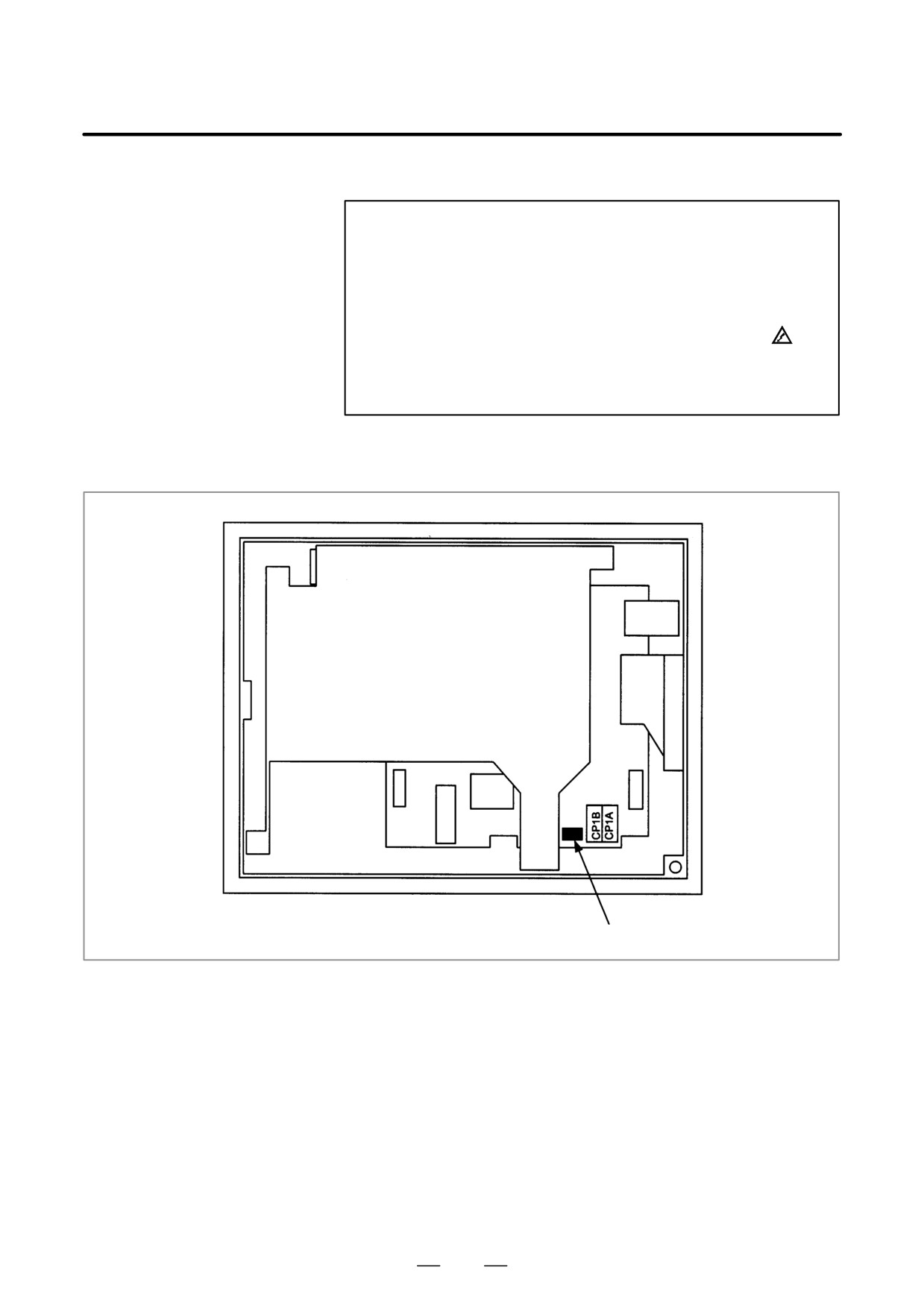
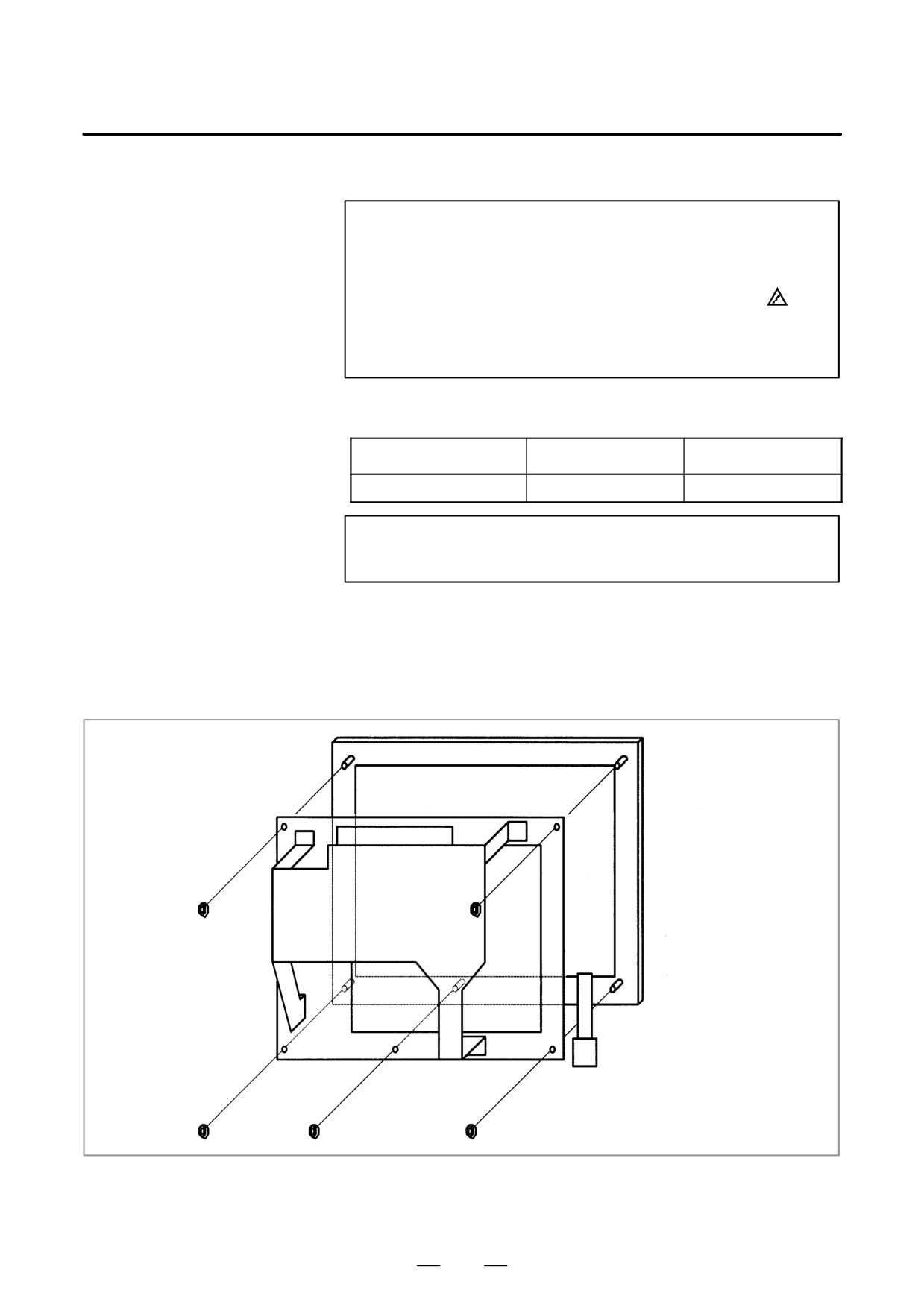
D Mounting position of the
fuse
LCD unit (rear face)
Fuse
D Information of the fuse
Ordering information: A02B-0265-K101
Rating:
2.0 A
Individual information: A60L-0001-0290#LM20C
348
4. STAND-ALONE TYPE i SERIES HARDWARE
B-63525EN/02
4.12
REPLACING THE
WARNING
LCD BACKLIGHT
The replacement described here should be performed by a
person fully trained in maintenance and safety. If the
cabinet is opened to replace the unit, take extreme care not
to touch any high-voltage area
(marked with
and
covered by a shock prevention cover). If the area is
uncovered, direct contact with this area will result in an
electric shock.
D Ordering information of
the backlight
Backlight
Ordering information
Individual information
For 9.5″ LCD
A02B-0281-K114
A61L-0001-0154#BLC
NOTE
The back-light of the 10.4I color LCD cannot be replaced.
D Replacing the backlight
(1) Remove soft key cable connector CK2, then remove the escutcheon
from the LCD unit.
If the unit has a touch panel, remove touch panel signal cable connector
CN1 as well.
Escutcheon
Soft key cable
CK2
349
4. STAND-ALONE TYPE i SERIES HARDWARE
B-63525EN/02
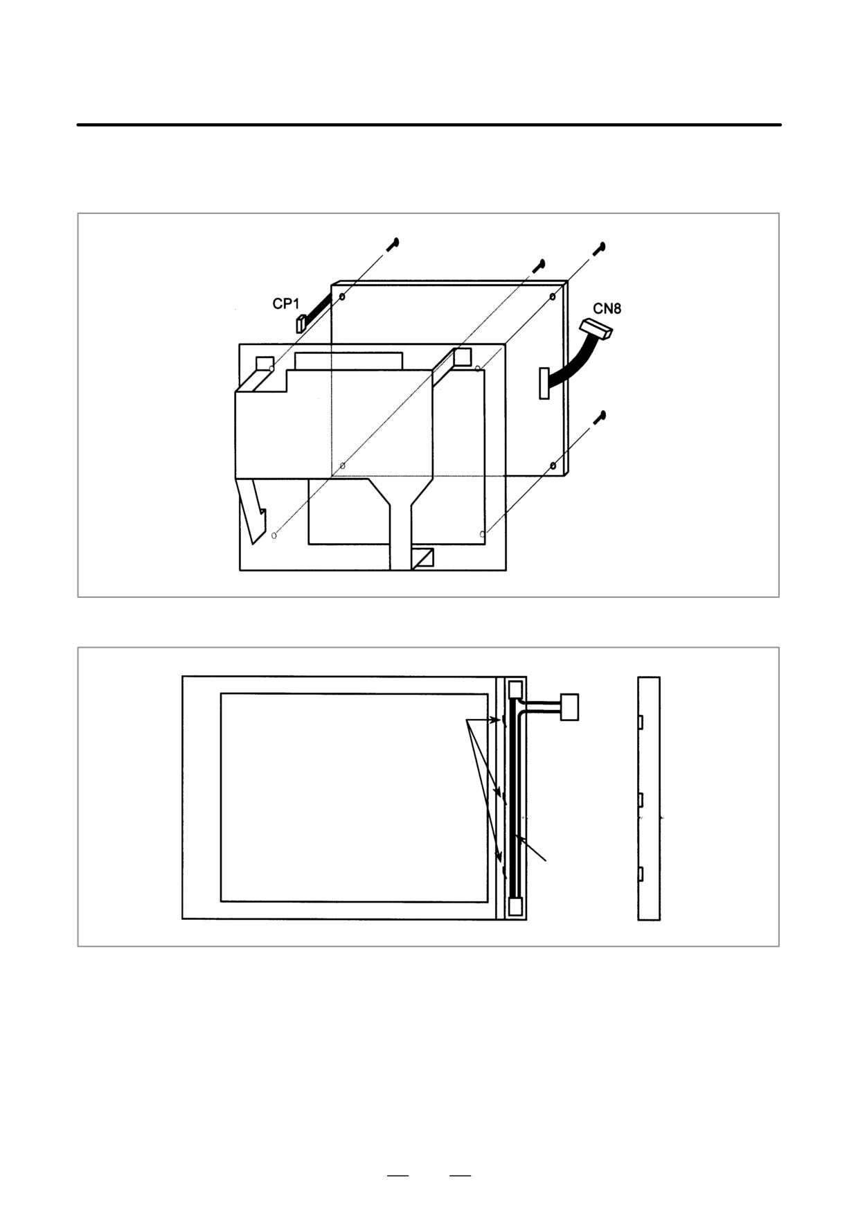
(2) Disconnect inverter cable connector CP1 and video signal cable
connector CN8, then remove the LCD panel from the unit.
LCD panel
(3) For 9.5″ monochrome LCD
Connector
Metal catch
Back of the
LCD panel
Backlight
(4) After replacing the backlight, assemble the unit, reversing the
disassembly procedure of steps (1) to (3).
During the assembly, take care to keep dust out.
350
4. STAND-ALONE TYPE i SERIES HARDWARE
B-63525EN/02
4.13
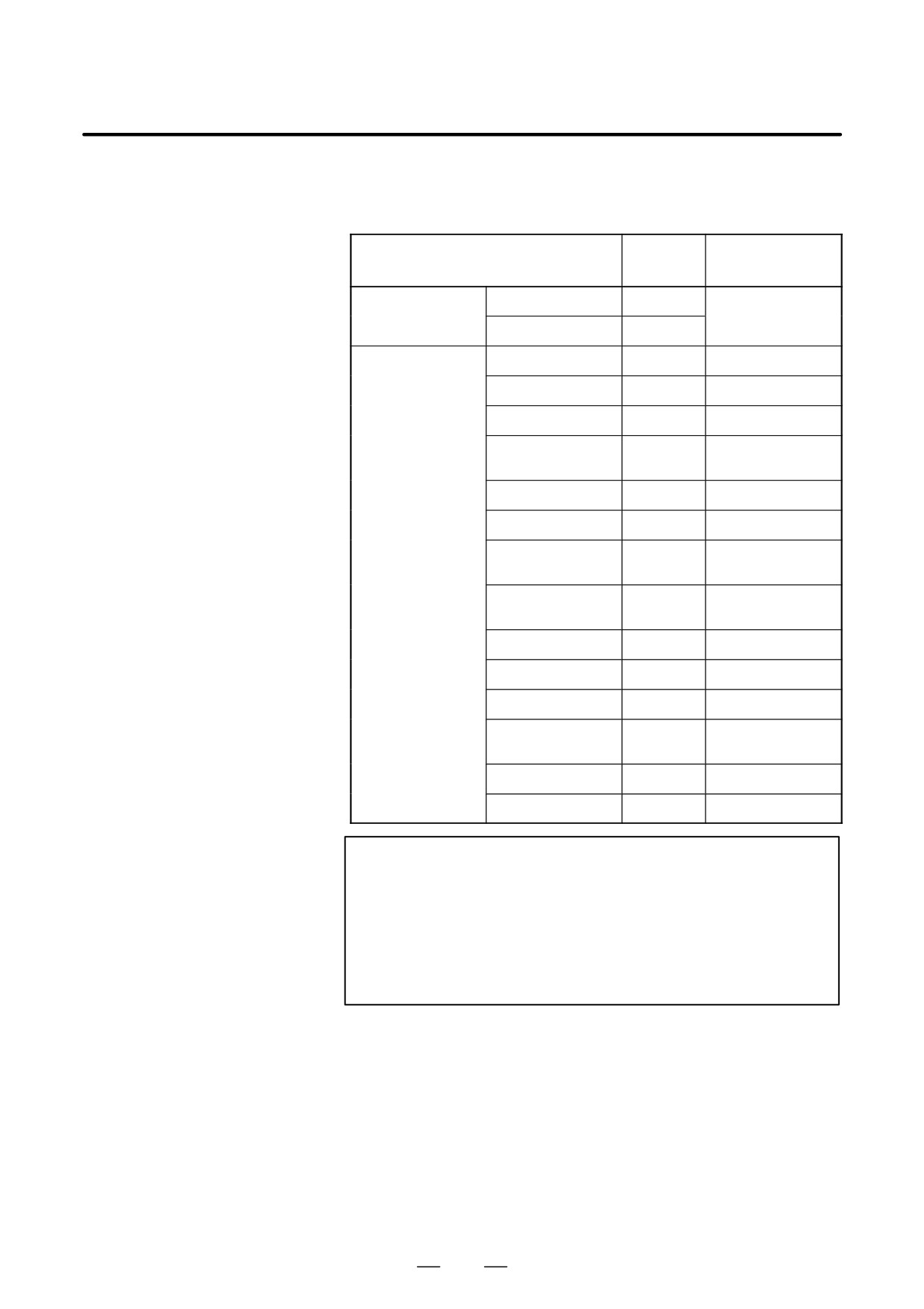
HEAT GENERATION
OF THE UNITS
Heat
Unit
Remarks
generation
Control unit
1-slot cabinet
30W
(*1)
3-slot cabinet
43W
Option board
HSSB board
4W
Sub-CPU board
14W
PMC C board
7W
Serialcommunication
7W
board
Symbol CAPi T board
10W
RISC board
9W
Data server board
6.3W
Including 0.3 W of the
ATA card(*2)
RISC + data server
15.3W
Including 0.3 W of the
board
ATA card(*2)
Loader control board
15W
(*3)
I/O Link II board
9W
Ethernet board
6W
DeviceNet interface
4W
board
PROFIBUS board
9W
FL-net board
7W
NOTE
1
The values
of the main CPU
board and MDI unit are
included. The values of option boards are not included.
2
The heat generation of the ATA flash card may be different
if a large-capacity card is used or if the card specifications
are changed.
3
The values are taken when 50% of inputs are turned on.
351
4. STAND-ALONE TYPE i SERIES HARDWARE
B-63525EN/02
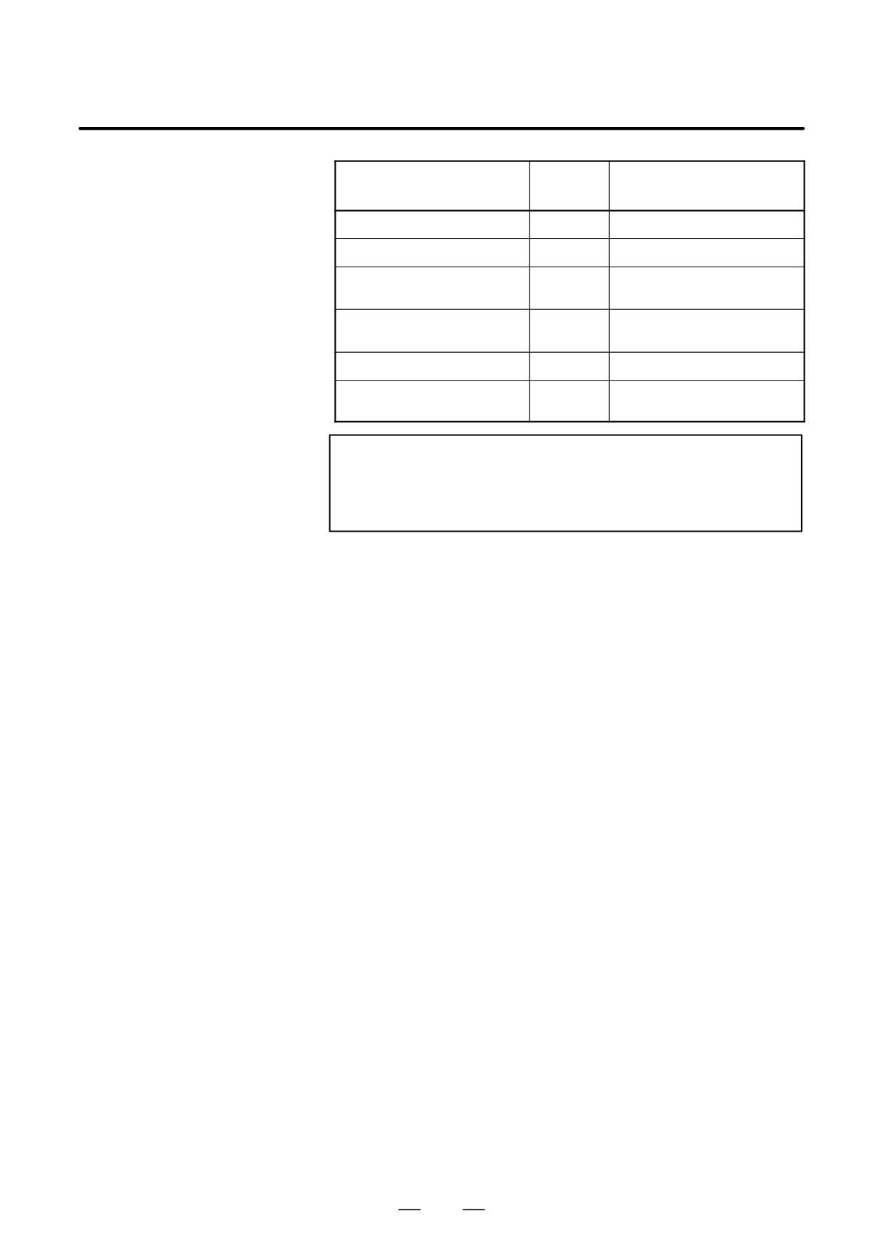
Heat
Unit
Remarks
generation
MDI unit
0W
Operator’s panel I/O module
12W
(*1)
Connector panel I/O module (ba-
8W
(*1)
sic)
Connector panel I/O module (ex-
5W
(*1)
pansion)
Separate detector interface unit
9W
Unit with 4 basic axes only
Separate detector interface unit
14W
4 basic axes + 4 additional
axes(*2)
NOTE
1
The values are taken when 50% of the module inputs are
turned on.
2
The heat generated in the separate detector is not included.
352
5. MATTERS COMMON TO BOTH LCD-MOUNTED TYPE
B-63525EN/02
AND STAND-ALONE TYPE i SERIES (HARDWARE)
MATTERS COMMON TO BOTH LCD-MOUNTED TYPE
AND STAND-ALONE TYPE i SERIES (HARDWARE)
5
This chapter describes the hardware common to the LCD-mounted type
i series and stand-alone type i series.
5.1
MOUNTING AND DEMOUNTING CARD PCBS . 354
5.2
MOUNTING AND DEMOUNTING
DIMM MODULES
357
5.3
MAINTENANCE OF HEAT EXCHANGER OF
HEAT PIPE TYPE
359
5.4
LIQUID CRYSTAL DISPLAY (LCD)
363
5.5
DISTRIBUTED I/O SETTING
368
5.6
REPLACING FUSES ON VARIOUS UNITS
371
5.7
ENVIRONMENTAL CONDITIONS
OUTSIDE CABINET
376
5.8
COUNTERMEASURES AGAINST NOISE
377
5.9
NOTES ON USING THE MDI UNIT
386
5.10 REPLACING THE MAINTENANCE PARTS
OF CNC DISPLAY UNIT FOR PC FUNCTIONS
AND PANEL i
387
5.11 REPLACING THE MAINTENANCE PARTS
OF CNC DISPLAY UNIT FOR is SERIES CNC . . .
395
353
5. MATTERS COMMON TO BOTH LCD-MOUNTED TYPE
AND STAND-ALONE TYPE i SERIES (HARDWARE)
B-63525EN/02
5.1
MOUNTING AND
WARNING
DEMOUNTING CARD
Only those personnel who have received approved safety
PCBS
and maintenance training may perform this replacement
work.
When opening the cabinet and replacing a card PCB, be
careful not to touch the high-voltage circuits (marked and
fitted with an insulating cover). Touching the uncovered
high-voltage circuits presents an extremely dangerous
electric shock hazard.
CAUTION
1
Before starting replacement work, back up the contents
(such as parameters and programs) of the SRAM memory
of the CNC. Otherwise, the contents of the SRAM memory
may be lost during replacement work.
2
If the SRMA data check method (parity check or ECC check)
has been changed after the replacement, a parity or ECC
alarm may occur at power-on, possibly causing damage to
the SRAM data. Back up the SRAM data before starting
replacement, and restore the data after completing the
replacement.
354
5. MATTERS COMMON TO BOTH LCD-MOUNTED TYPE
B-63525EN/02
AND STAND-ALONE TYPE i SERIES (HARDWARE)
5.1.1
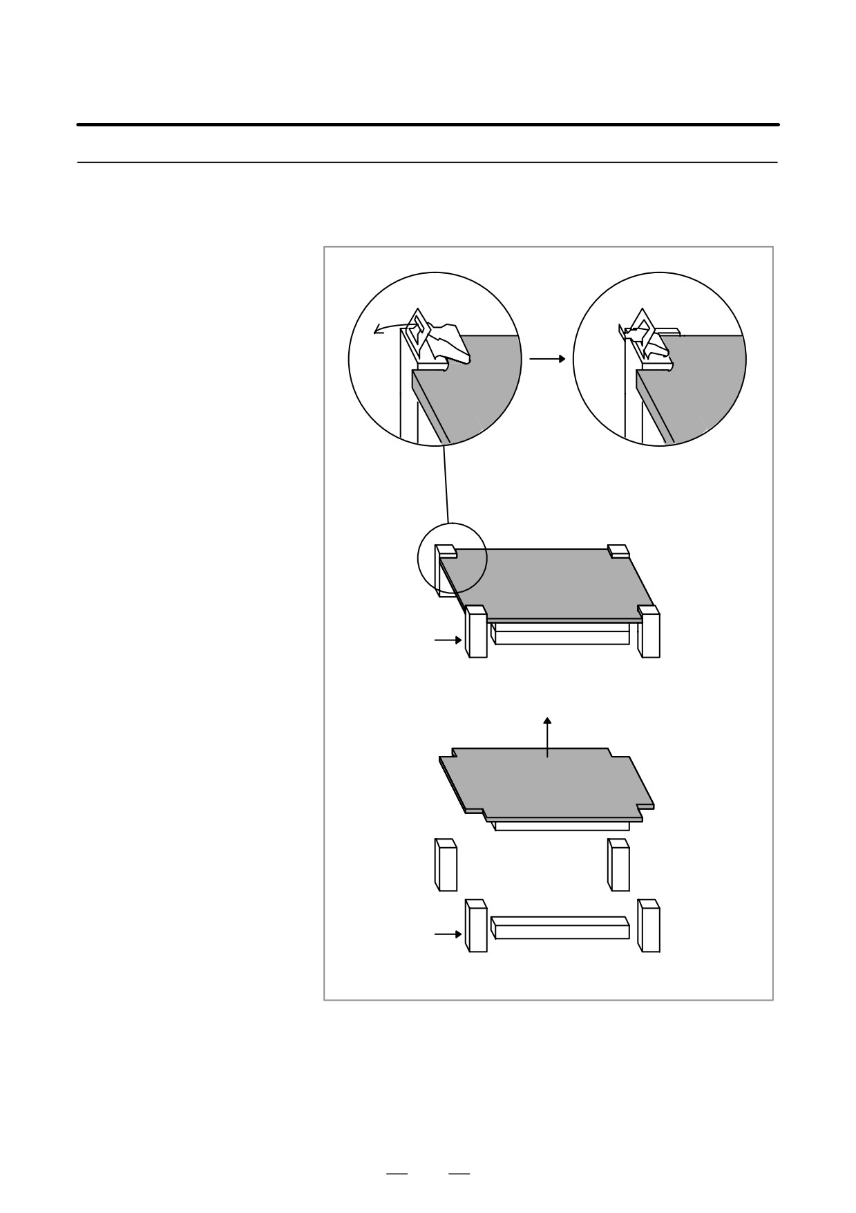
1) Pull outward the claw of each of the four spacers used to secure the card
PCB, then release each latch. (See Fig. a.)
Demounting a Card
2) Extract the card PCB upward. (See Fig. b.)
PCB
Card PCB
Card PCB
Card PCB
Fig. a Spacer
Connector
Card PCB
Fig. b
Spacer
Connector
355
5. MATTERS COMMON TO BOTH LCD-MOUNTED TYPE
AND STAND-ALONE TYPE i SERIES (HARDWARE)
B-63525EN/02
5.1.2
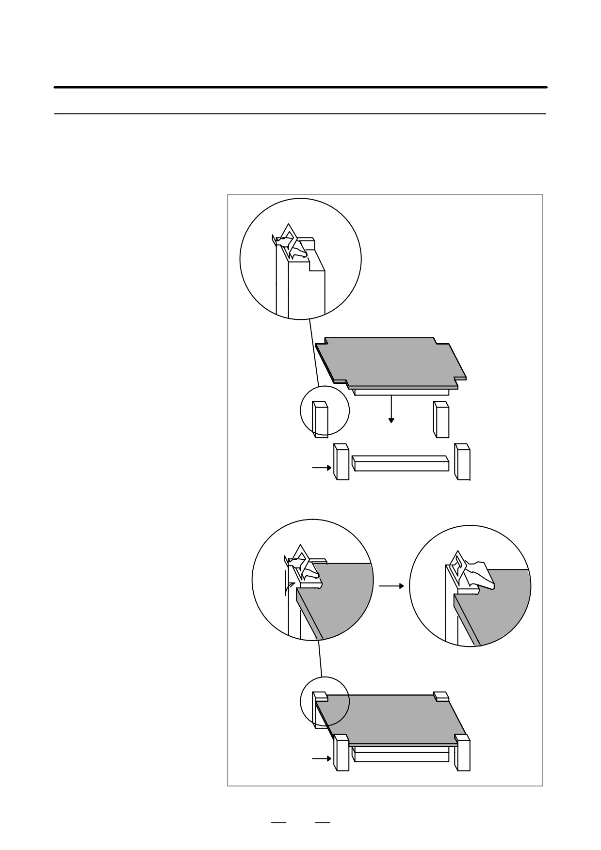
1) Check that the claw of each of the spacers is latched outward, then
insert the card PCB into the connector.
(See Fig. c.)
Mounting a Card PCB
2) Push the claw of each spacer downward to secure the card PCB. (See
Fig. d.)
Card PCB
Fig. c Spacer
Connector
Card PCB
Card PCB
Card PCB
Fig. d Spacer
Connector
356
5. MATTERS COMMON TO BOTH LCD-MOUNTED TYPE
B-63525EN/02
AND STAND-ALONE TYPE i SERIES (HARDWARE)
5.2
MOUNTING AND
WARNING
DEMOUNTING DIMM
Only those personnel who have received approved safety
MODULES
and maintenance training may perform this replacement
work.
When opening the cabinet and replacing a module, be
careful not to touch the high-voltage circuits (marked and
fitted with an insulating cover). Touching the uncovered
high-voltage circuits presents an extremely dangerous
electric shock hazard.
CAUTION
Before starting replacement work, back up the contents
(such as parameters and programs) of the SRAM memory
of the CNC. Otherwise, the contents of the SRAM memory
may be lost during replacement work.
Before replacing an SRAM module, be sure to back up the
contents of the SRAM module.
357
5. MATTERS COMMON TO BOTH LCD-MOUNTED TYPE
AND STAND-ALONE TYPE i SERIES (HARDWARE)
B-63525EN/02
5.2.1
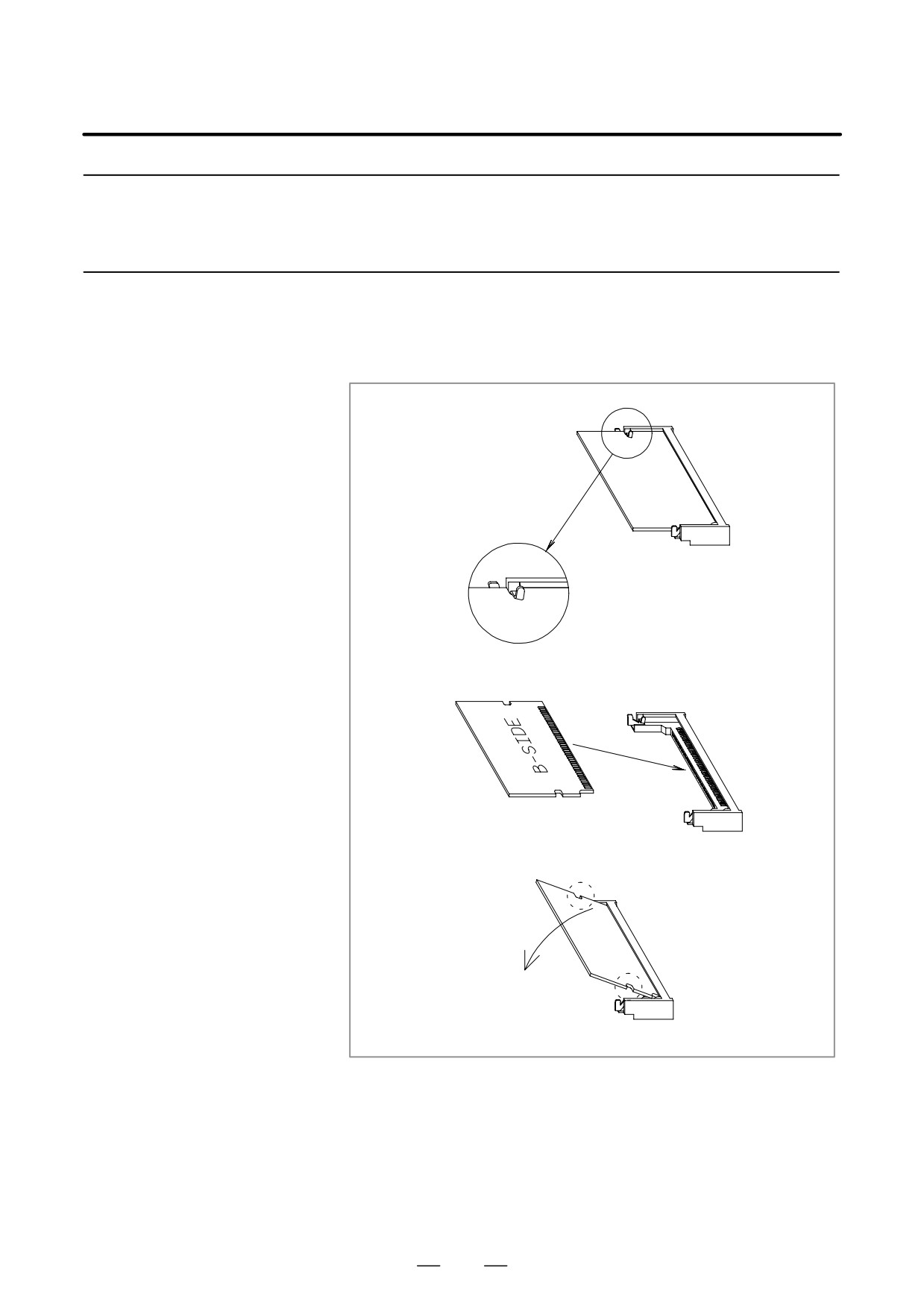
1) Open the claw of the socket outward. (See Fig. a.)
Demounting a DIMM
2) Extract the module slantly upward. (See Fig. b.)
Module
1) Insert the module slantly into the module socket, with side B facing
5.2.2
upward. (See Fig. b.)
Mounting a DIMM
2) Push the module downward until it is locked. (See Fig. c.)
Module
At this time, push it down with pushing two points of (*) in the figure.
Fig. a
Fig. b
Fig. c
(*)
(*)
358
5. MATTERS COMMON TO BOTH LCD-MOUNTED TYPE
B-63525EN/02
AND STAND-ALONE TYPE i SERIES (HARDWARE)
The performance of the heat exchanger degrades due to a buildup of dirt.
5.3
Clean the heat exchanger periodically. The cleaning interval depends on
MAINTENANCE OF
the installation environment. So, clean the heat exchanger at appropriate
HEAT EXCHANGER
intervals according to the level of dirt built up.
OF HEAT PIPE TYPE
WARNING
High voltage is applied to the heat exchanger of heat pipe
type. Before maintaining the heat exchanger of heat pipe
type, always turn off the power to the CNC.
When opening the cabinet and replacing a heat exchanger
of heat pipe type, be careful not to touch the high-voltage
circuits (marked
and fitted with an insulating cover).
Touching the uncovered high-voltage circuits presents an
extremely dangerous electric shock hazard.
359
5. MATTERS COMMON TO BOTH LCD-MOUNTED TYPE
AND STAND-ALONE TYPE i SERIES (HARDWARE)
B-63525EN/02
Cleaning and replacing
the air filter
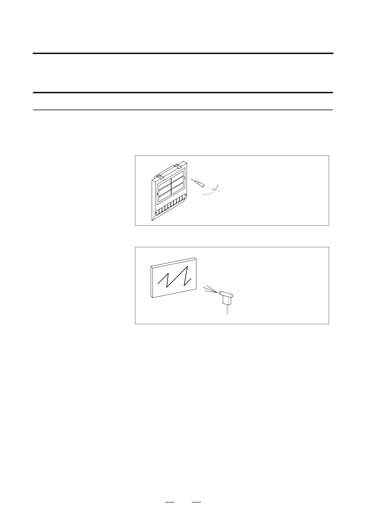
Procedure for cleaning and replacing the air filter
1
Before cleaning and replacing the air filter, turn off the fan power
supply.
2
Remove the filter cover, then demount the filter.
When removing the cover, press the claw placed in
the groove on both sides inward with a screwdriver.
3
Blow air against both sides of the filter to remove dust.
4
When the filter is dirty extremely, wash it with a solution of water and
neutral detergent, and rinse it with fresh water, then allow it dry
naturally.
Alternatively, replace it with a new filter (use only the specified filter).
5
Set the cleaned or new filter. Next, align the claws with the grooves,
then press them to reinstall the cover. Check that the cover is not
removed when it is pulled toward you.
360
5. MATTERS COMMON TO BOTH LCD-MOUNTED TYPE
B-63525EN/02
AND STAND-ALONE TYPE i SERIES (HARDWARE)
Cleaning the heat
exchanger
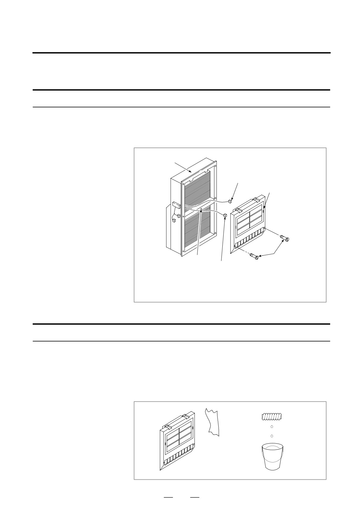
Procedure for cleaning the heat exchanger
1
Before cleaning the heat exchanger, turn off the fan power supply.
2
Demount the external fan unit from the main body of the heat
exchanger.
Main body of the
heat exchanger
Fan power cable
(Unplug the connector.)
External fan unit
Mounting screw B (1 piece)
Mounting screw A (2 pieces)
Ground wire (The ground wire can be disconnected by
removing the fan mounting screws.)
Remove the two mounting screws (A) used for mounting the external fan unit, then
demount the unit by sliding it downward. Next, disconnect the fan power cable and
ground wire. Remove mounting screw (B).
D Cleaning the fan unit
Procedure for cleaning the fan unit
1
Remove any buildup of dust, dirt, and mist from the fan motor and fan
mounting case with a dry waste cloth. If dirt such as mist cannot be
removed easily, use a waste cloth moistened with a solution of water
and neutral detergent after squeezing it softly. In this case, be careful
not to allow a solution of water and neutral detergent to enter the
electric circuitry such as the rotor of the fan motor.
361