FANUC Series 16i/160i/160is-MODEL B, Series 18i/180i/180is-MODEL B, Series 21i/210i/210is-MODEL B. MAINTENANCE MANAUL - page 11
4. STAND-ALONE TYPE i SERIES HARDWARE
B-63525EN/02
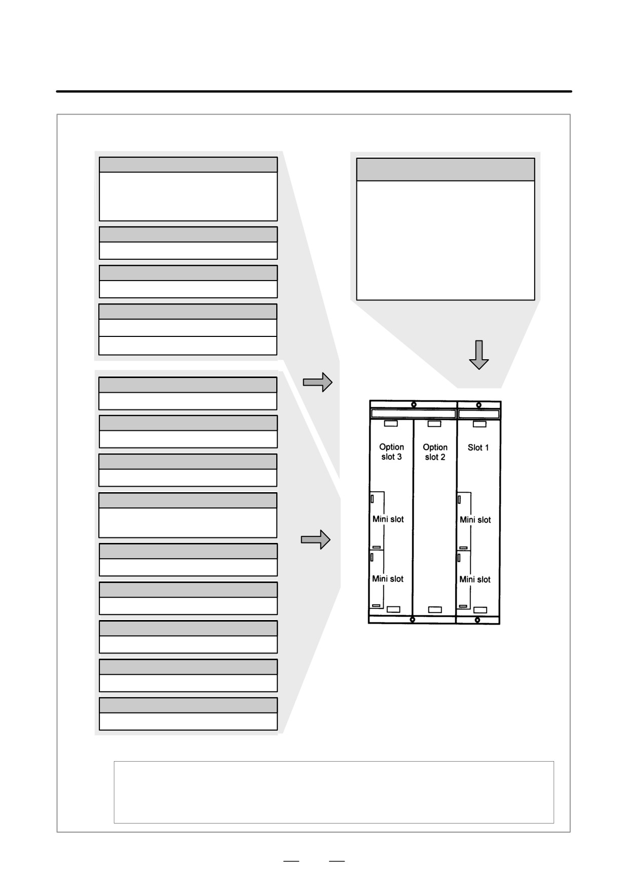
Sub-CPU board(*2)
Main CPU board
Sub-CPU for two-path control
⋅
2-axis to 8-axis control
CPU for controlling CNC
⋅ Spindle interface
⋅ Power
⋅ Analog output
⋅
2-axis to 8-axis control
⋅ Spindle interface
⋅ I/O Link
RISC board (M series only)(*1)
⋅ PMC-SB7
⋅ Analog output (option)
High-precision contour control function
⋅ High-speed DI
⋅ RS-232C x 2
Data server board(*1)
⋅ Memory card interface
⋅ Display interface
Data server function (ATA card)
⋅ Ethernet
RISC + data server board (M series only)(*1)
Mounted in slot 1
High-precision contour control function
Basic system
Data server function (ATA card)
Option
Serial communication board(*3)
Remote buffer/DNC1/DNC2
PMC C board(*3)
C function for PMC
Super CAPi T board (T series only)(*3)
Graphic conversation
HSSB interface board(*3)
Mini-slot
options
High-speed serial bus interface
I/O Link-II board(*3)
I/O Link-II interface
Ethernet board(*3)
Ethernetinterface
DeviceNet interface board(*3)
1-slot cabinet or
DeviceNet interface
3-slot cabinet
PROFIBUS board(*3)
PROFIBUS function
FL-net board(*3)
FL-net function
The mounting position of an option board depends on the board type, as shown below:
The option board marked with *1 fits into option slot 2.
The option board marked with *2 fits into option slot 3.
The option board marked with *3 fits into a mini slot (of any slot).
272
4. STAND-ALONE TYPE i SERIES HARDWARE
B-63525EN/02
4.2.2
Series 18i/180i/180is
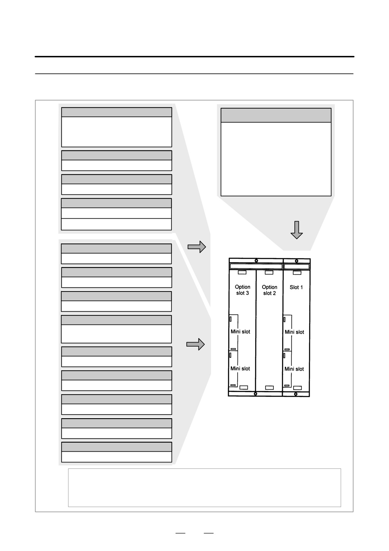
Sub-CPU board(*2)
Main CPU board
Sub-CPU for two-path control
⋅
2-axis to 6-axis control
CPU for controlling CNC
⋅ Spindle interface
⋅ Power
⋅ Analog output
⋅
2-axis to 6-axis control
⋅ Spindle interface
⋅ I/O Link
RISC board (M series only)(*1)
⋅ PMC-SB7
⋅ Analog output (option)
High-precision contour control function
⋅ High-speed DI
⋅ RS-232C x 2
Data server board(*1)
⋅ Memory card interface
⋅ Display interface
Data server function (ATA card)
⋅ Ethernet
RISC + data server board (M series only)(*1)
Mounted in slot 1
High-precision contour control function
Basic system
Data server function (ATA card)
Option
Serial communication board(*3)
Remote buffer/DNC1/DNC2
PMC C board(*3)
C function for PMC
Symbol CAPi T board (T series only)(*3)
Graphic conversation
HSSB interface board(*3)
Mini-slot
options
High-speed serial bus interface
I/O Link-II board(*3)
I/O Link-II interface
Ethernet board(*3)
Ethernetinterface
DeviceNet interface board(*3)
1-slot cabinet or
DeviceNet interface
3-slot cabinet
PROFIBUS board(*3)
PROFIBUS function
FL-net board(*3)
FL-net function
The mounting position of an option board depends on the board type, as shown below:
The option board marked with *1 fits into option slot 2.
The option board marked with *2 fits into option slot 3.
The option board marked with *3 fits into a mini slot (of any slot).
273
4. STAND-ALONE TYPE i SERIES HARDWARE
B-63525EN/02
4.2.3
Series 21i/210i/210is
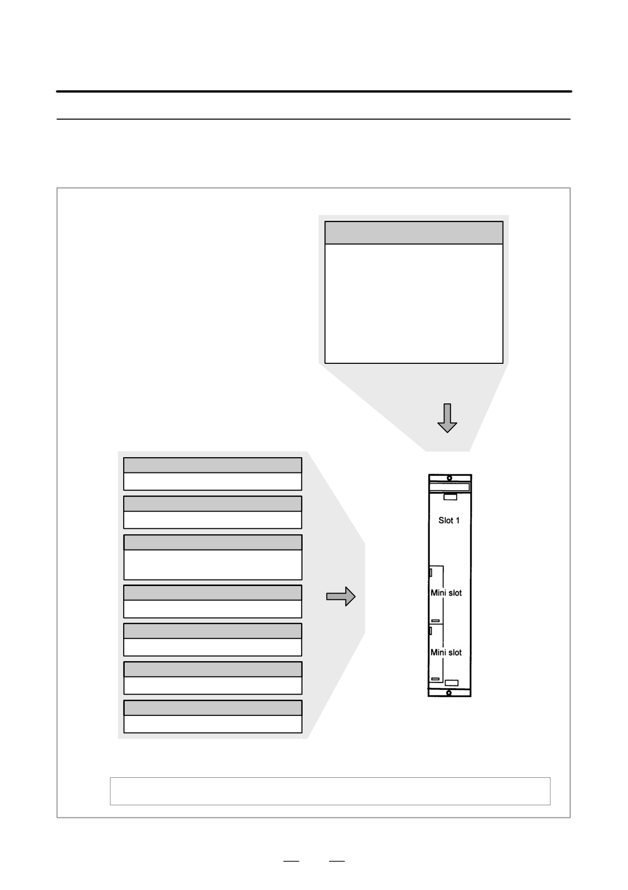
Main CPU board
CPU for controlling CNC
⋅ Power
⋅
2-axis to 4-axis control
⋅ Spindle interface
⋅ I/O Link
⋅ PMC-SA1/SB7
⋅ Analog output (option)
⋅ High-speed DI
⋅ RS-232C x 2
⋅ Memory card interface
⋅ Display interface
⋅ Ethernet (option)
Mounted in slot 1
Basic system
Serial communication board
Remote buffer/DNC1/DNC2
PMC C board
C function for PMC
HSSB interface board
High-speed serial bus interface
Mini-slot
options
I/O Link-II board
I/O Link-II interface
DeviceNet interface board
DeviceNet interface
PROFIBUS board
PROFIBUS function
FL-net board
1-slot cabinet
FL-net function
These option boards are mounted in mini slots (of any slot).
274
4. STAND-ALONE TYPE i SERIES HARDWARE
B-63525EN/02
4.3
TOTAL CONNECTION
DIAGRAMS
275
4. STAND-ALONE TYPE i SERIES HARDWARE
B-63525EN/02
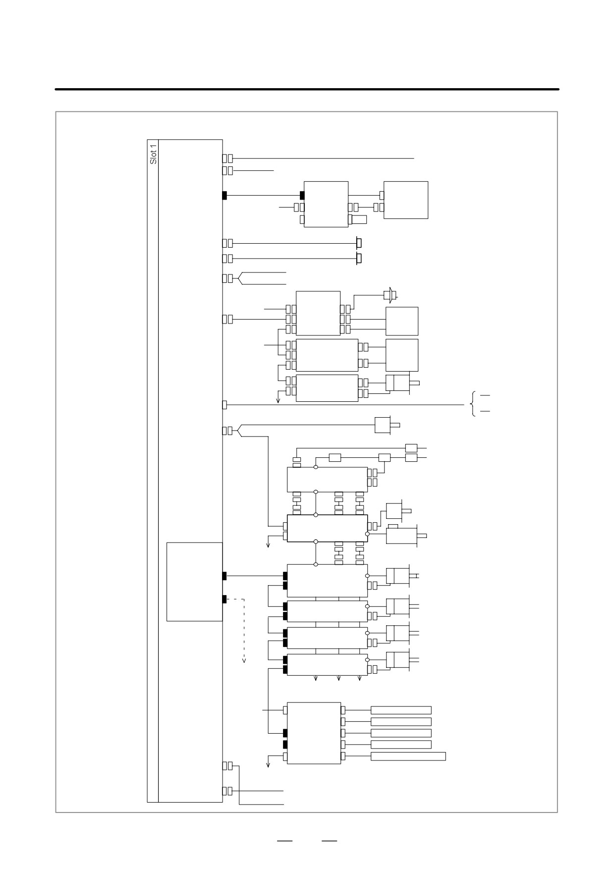
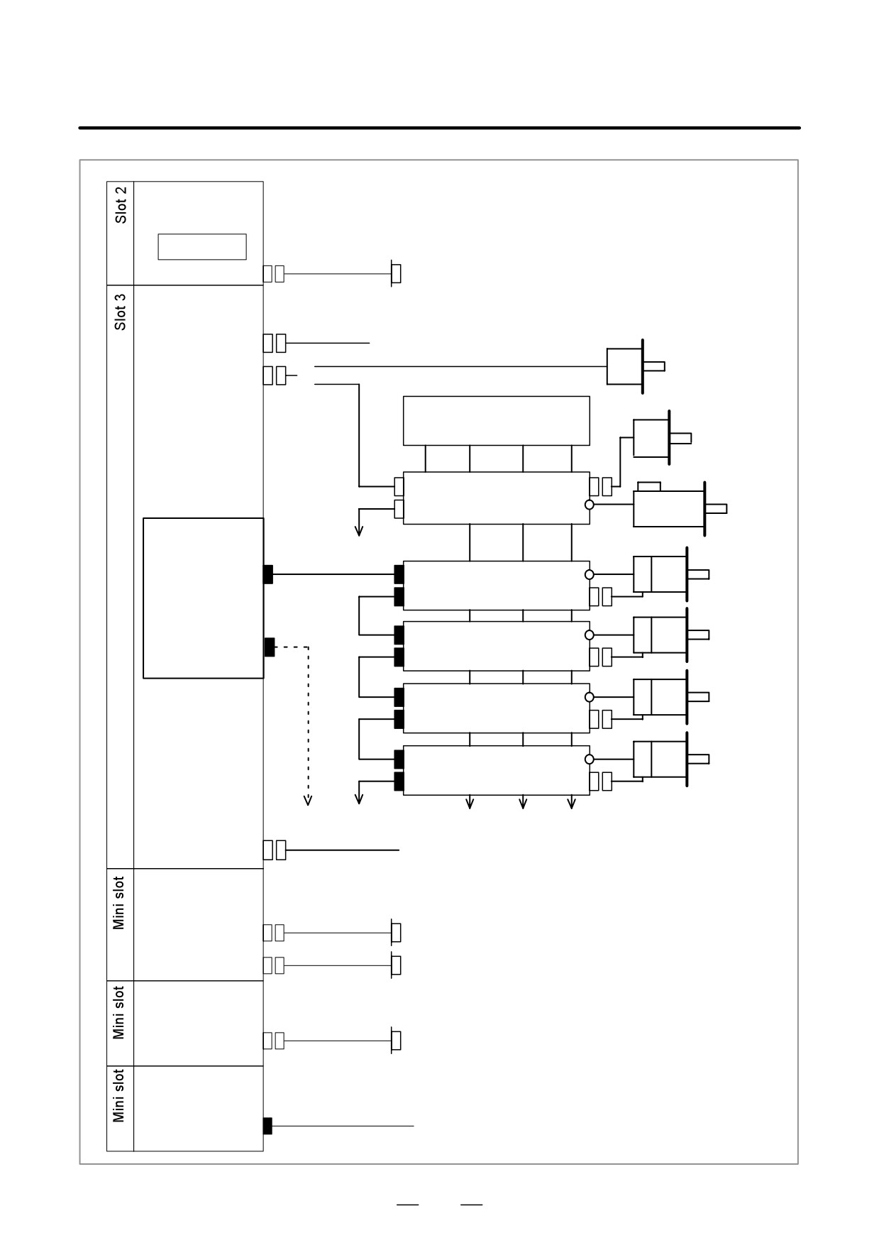
Stand-alone type control unit
Main board
24V-IN(CP1)
24-VDC power
24V-OUT(CP2)
To I/O unit, etc.
Optical fiber cable
LCD UNIT
MDUNIT
LCD(COP20A)
COP20B
CK2
24VDC
CP1A CA55
CK1
CP1B
Memory card
(Touch panel)
R232-1(JD5A)
RS-232-C I/O unit
R232-2(JD5B)
RS-232-C I/O unit
Analog output for tool drive
A-OUT&HDI(JA40)
High-speed skip input
Distributed
Manual pulse generator
I/O board
24VDC
CPD1
JA3
I/O Link(JD44A)
JD1B
Operator’s
panel
JD1A
24VDC
CPD1
Distributed I/O
Power
JD1B
board, I/O unit,
magnetics
JD1A
etc.
cabinet
JD1B
Servo motor
β amplifier with
JD1A
I/O Link
Detachable LCD/MDI
LINK(JD45)
MDI unit
Position coder
SPDL&POS(JA41)
Circuit breaker
200VAC
AC reactor
200VAC
MCC
Circuit breaker
CX1AÁTB2Á
CX3
PSM
CX4
JX1B
CX1BÁTB1Á
Position coder
ÁÁ
CX1AÁTB1Á
CX2A JX1A
JY2
JA7B
SPM
TB2
JA7A
TB1
CX2B JX1B
Á
Servo card
To 2nd spindle
ÁÁ
Serial spindle motor
Optical fiber cable
TB1
ÁÁ
CX2A JX1A
FSSB(COP10A-1)
Axis-1 servo motor
COP10B
SVM
TB2
JF1
Á
COP10A
CX2B
FSSB(COP10A-2)
TB1
JX1B
COP10B
Axis-2 servo motor
SVM
COP10A
Á
COP10B
Á
Axis-3 servo motor
SVM
COP10A
Á
COP10B
Axis-4 servo motor
SVM
Á
COP10A
Up to 4 to 8 axes, depending on the model (In this figure, a one-axis amplifier is used.)
Separate detector interface unit 1
24VDC
CP11A
JF101
Linear scale, axis 1
JF102
Linear scale, axis 2
COP10B
JF103
Linear scale, axis 3
COP10A JF104
Linear scale, axis 4
CNF1
JA4A
Absolute scale battery
ETHERNET(CD38A)
(Required only when an absolute scale is used)
Separate detector
(Cannot be used in 21i/210i)
interface unit 2
SV-CHK(CA69A)
Servo check board
Ethernet
276
4. STAND-ALONE TYPE i SERIES HARDWARE
B-63525EN/02
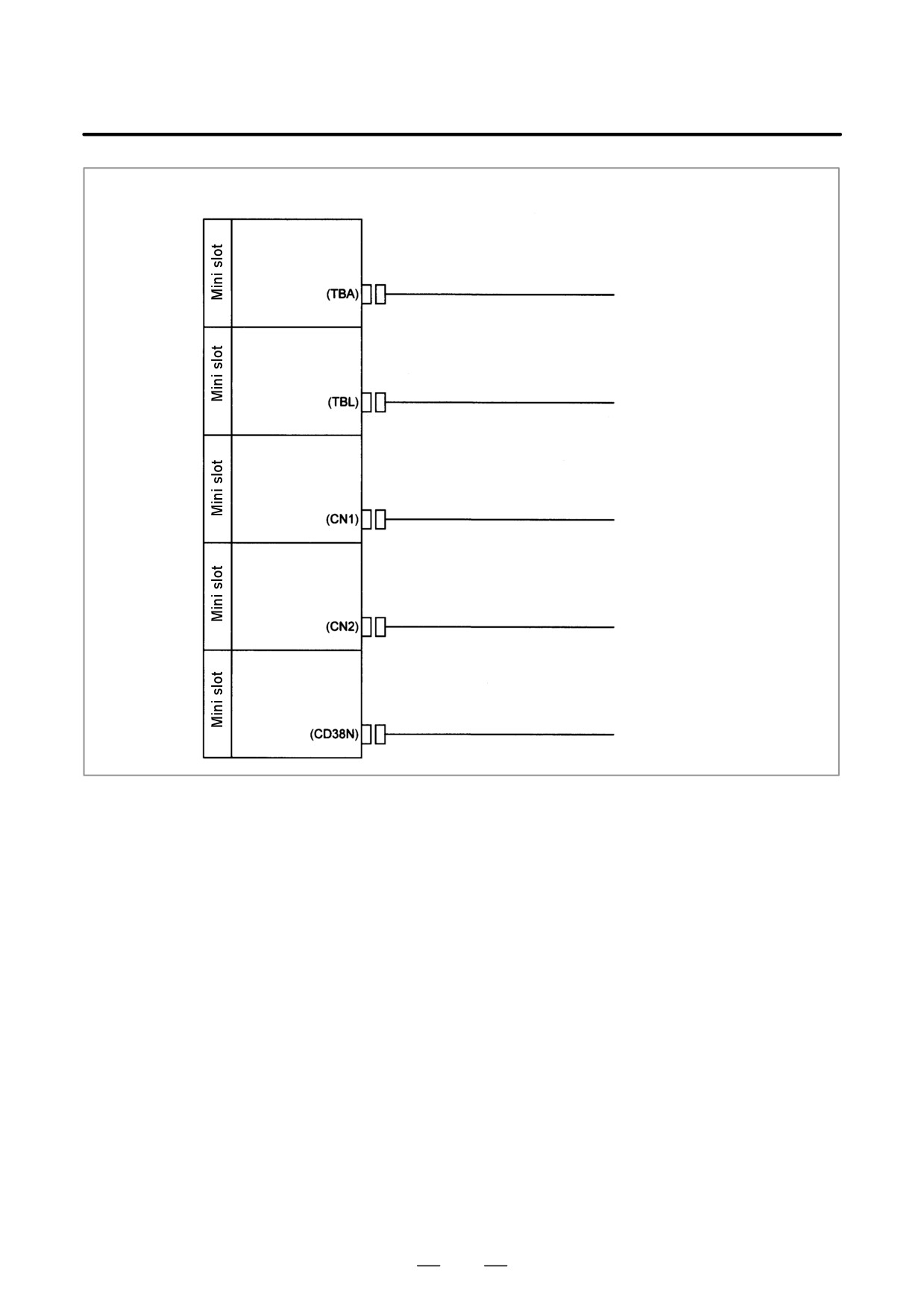
Stand-alone type control unit
Data server board
(cannot be used in
21i/210i/210is)
ATA card
(CD38M)
Ethernet
Sub-CPU board
(cannot be used in
21i/210i/210is)
Analog output for tool drive
A-OUT(JA40)
Position coder
SPDL&POS(JA41)
{
PSM
Position coder
Spindle motor
SPM
Servo card
To 2nd spindle
FSSB(COP10A-1)
Sub axis-1
COP10B
SVM
servo motor
Optical fiber cable(*)
COP10A
Sub axis-2
COP10B
FSSB(COP10A-2)
SVM
servo motor
COP10A
Sub axis-3
COP10B
SVM
servo motor
COP10A
Sub axis-4
COP10B
SVM
servo motor
COP10A
(Up to 6 to 8 axes, depending on the model)
SV-CHK(CA69B)
Servo check board
Serial communication
board
Remote buffer board
DNC1 board
DNC2 board
R232-3
RS-232-C I/O unit (when remote buffer board or DNC2 board is used)
R422-1
RS-422 I/O unit (when remote buffer board or DNC1 board is used)
Ethernet (cannot be
used in 21i/210i/210is)
(CD38L)
Ethernet
HSSB board
HSSB(COP70)
Personal Computer
Optical fiber cable
277
4. STAND-ALONE TYPE i SERIES HARDWARE
B-63525EN/02
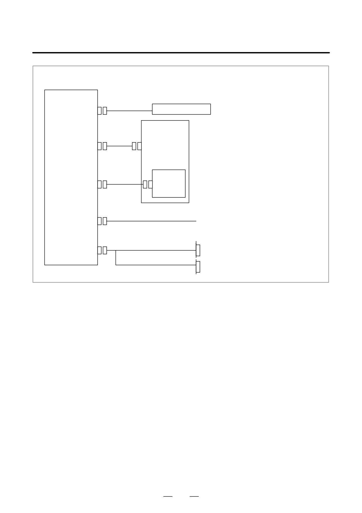
When an option board is used
I/O Link II board
To another unit
DeviceNet board
To another unit
PROFIBUS board
(master)
To another unit
PROFIBUS board
(slave)
To another unit
FL-net board
To another unit
278
4. STAND-ALONE TYPE i SERIES HARDWARE
B-63525EN/02
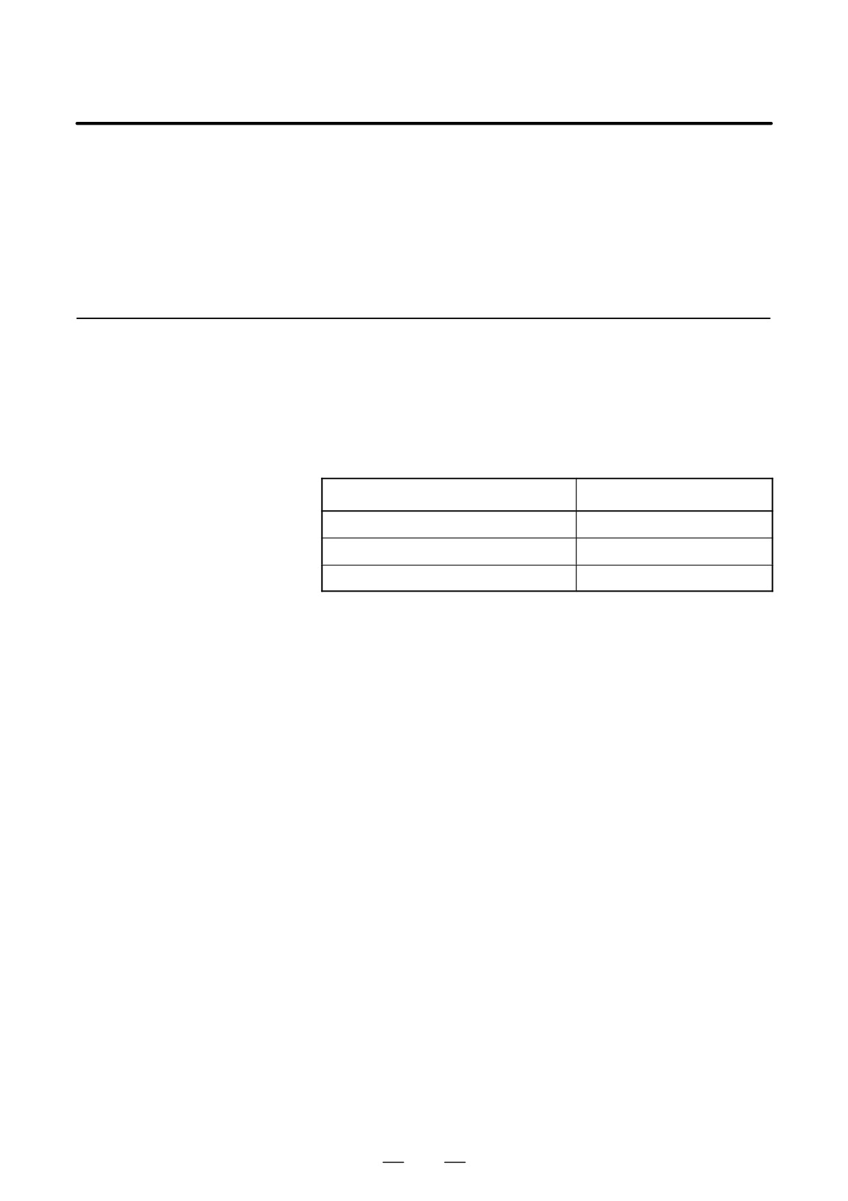
For the is series CNC display unit, the additional connection shown below is required on the unit.
24VDC Power Supply
DC24V-IN(CP1)
MDI unit
dedicated to PCs
Soft Key Cable
Soft Key(CK2)
Backup(CA75)
Backup Unit
PC Side Ethernet
Hub, etc.
(CD38S)
PC Side
RS-232-C I/O Device
RS-232-C USB(JD48)
USB Keyboard Printer
279
4. STAND-ALONE TYPE i SERIES HARDWARE
B-63525EN/02
4.4
CONNECTOR AND
CARD
CONFIGURATIONS
OF PRINTED CIRCUIT
BOARDS
4.4.1
Main CPU Board of
Series 16i/18i/21i/160i/
180i/210i/160is/180is/
210is
D Specifications
Item
Code
Main CPU board of Series 16i/160i/160is
A16B-3200-0420
Main CPU board of Series 18i/180i/180is
A16B-3200-0421
Main CPU board of Series 21i/210i/210is
A16B-3200-0425
280
4. STAND-ALONE TYPE i SERIES HARDWARE
B-63525EN/02
D Mounting positions of
connectors, LEDs, etc.
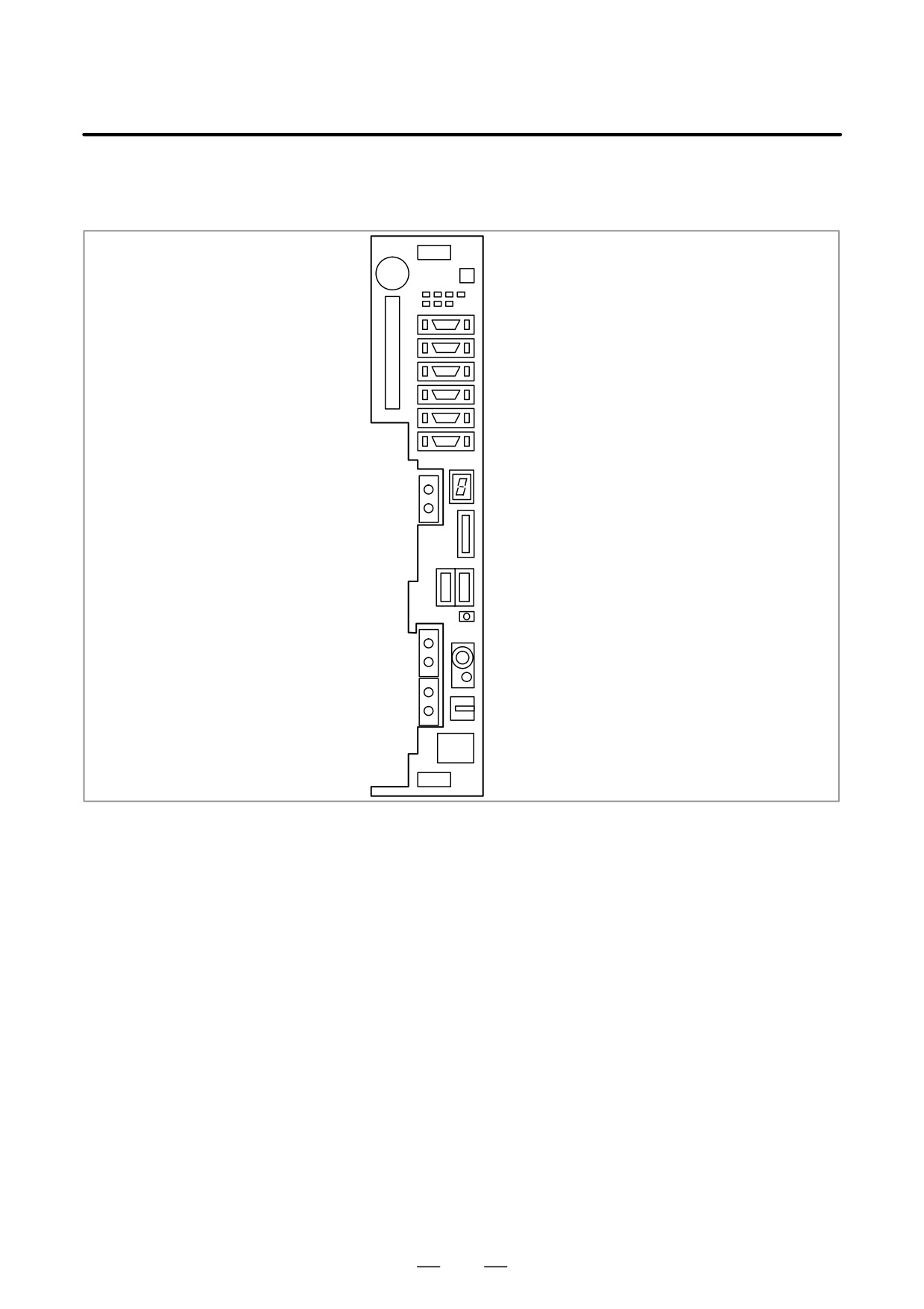
MAIN
BAT1: Battery
Battery case
LEDs
JD5A: RS232C serial port
JD5B: RS232C serial port
CNM1B: Memory card
JD1A: I/O Link
JA40: Analog output/high-speed DI
JA41: Serial spindle/position coder
JD45: CRT LINK/MDI
STATUS: 7-Segment LED
COP20A : Connection to LCD unit
CA69A: Servo check
CP1(right): 24VDC IN
CP2(left): 24VDC OUT
FUSE: Fuse burn-out detection LED
COP10A-2:FSSB
MTSW: Rotary switch
PSW: Push switch
COP10A-1:FSSB
SG connection terminal
CD38A:Ethernet
STATUS 7-segment LED: Used for setting and maintenance operations, in combination with the
MTSW rotary switch and PSW push switch described below.
MTSW rotary switch:
This rotary switch is used for setting and maintenance operations, in
combination with the STATUS 7-segment LED and the PSW push
switch.
PSW push switch:
This push switch is used for setting and maintenance operations, in
combination with the STATUS 7-segment LED and the MTSW rotary
switch.
281
4. STAND-ALONE TYPE i SERIES HARDWARE
B-63525EN/02
D Mounting positions of
cards and DIMM modules
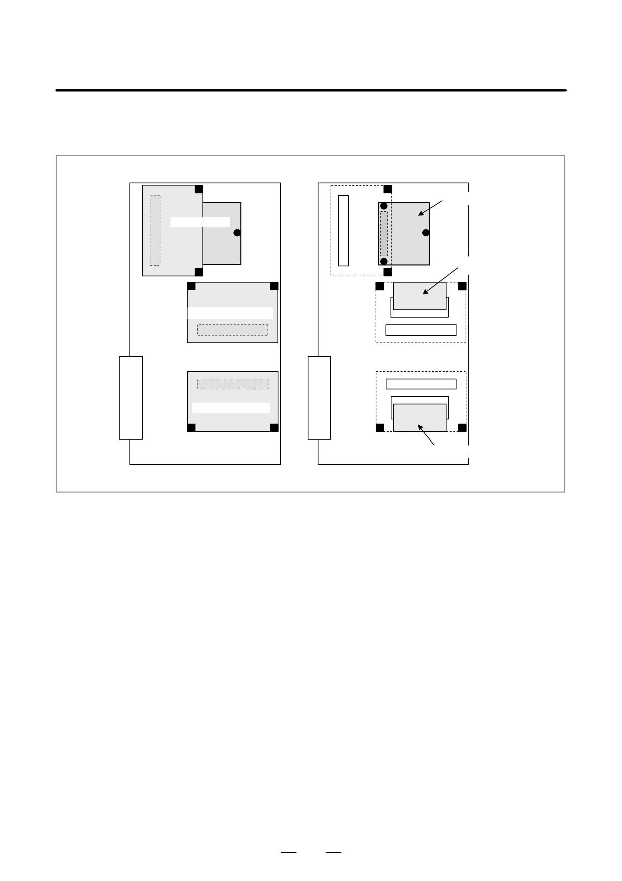
(4) Power supply unit
(1) CPU card
(5) Analog spindle
module
(2) Display control card
(3) Axis control card
(6) FROM/SRAM module
282
4. STAND-ALONE TYPE i SERIES HARDWARE
B-63525EN/02
No.
Item
Code
Function
Remarks
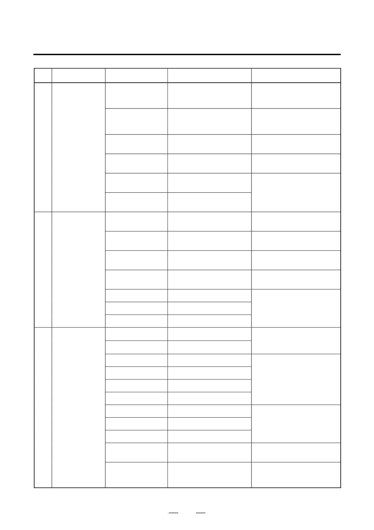
(1)
CPU card
A20B-3300-0310
DRAM 16MB
For Series 16i/18i/160i/180i/
160is/180is
A20B-3300-0311
DRAM 32MB
For Series 16i/18i/160i/180i/
160is/180is
A20B-3300-0291
DRAM 16MB
For Series 21i/210i/210is
A20B-3300-0290
DRAM 32MB
For Series 21i/210i/210is
A20B-3300-0312
DRAM 16MB
When the embedded Ethernet is
For Series 21i/210i/210is
used with Series 21i/210i/210is
A20B-3300-0313
DRAM 32MB
For Series 21i/210i/210is
(2)
Display control
A20B-3300-0340
LCD/MDI
card
Embedded ethernet
A20B-3300-0360
Display link
Embedded ethernet
A20B-3300-0362
MDI
Embedded ethernet
A20B-3300-0364
Without display unit
Embedded ethernet
A20B-3300-0341
LCD/MDI
When the embedded Ethernet is
not used with Series 21i/210i/
A20B-3300-0361
Display link
210is
A20B-3300-0363
MDI
(3)
Axis control card
A20B-3300-0033
Axis control 2-axes
Servo software
Series 9090
A20B-3300-0032
Axis control 4-axes
(21i)
A20B-3300-0243
Axis control 2-axes
Servo software
Series 90B0
A20B-3300-0242
Axis control 4-axes
A20B-3300-0241
Axis control 6-axes
A20B-3300-0240
Axis control 8-axes
A20B-3300-0248
Axis control 4-axes
Servo software
Series 90B0
A20B-3300-0245
Axis control 6-axes
(High-speed HRV)
A20B-3300-0244
Axis control 8-axes
A20B-3300-0246
Learning controlled axis control
Servo software
Series 90B3/90B7
A20B-3300-0247
Learning controlled axis control
Servo software
Series 90B3/90B7
(High-speed HRV)
283
4. STAND-ALONE TYPE i SERIES HARDWARE
B-63525EN/02
No.
Item
Code
Function
Remarks
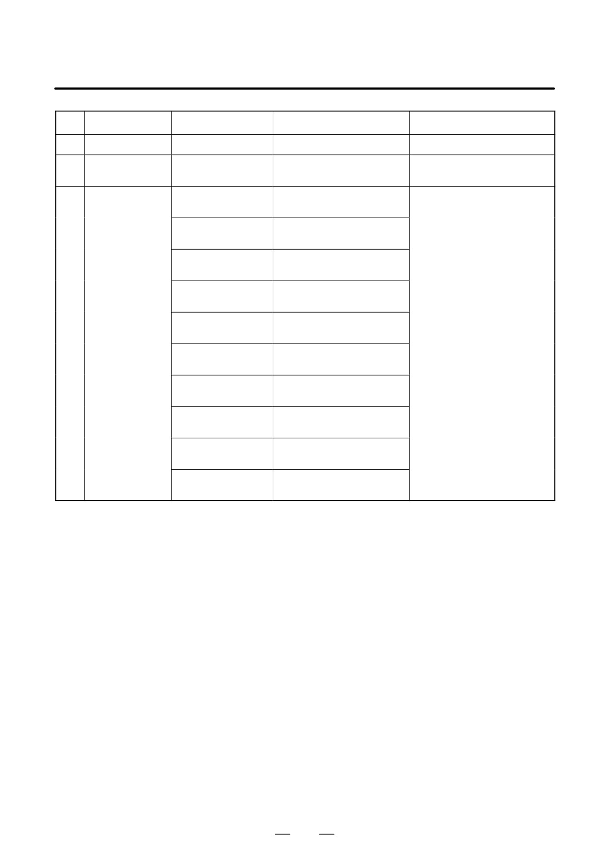
(4)
Power unit
A20B-8100-0851
(5)
Analog spindle
A20B-3900-0170
Analog spindle position coder
module
(6)
FROM/SRAM
A20B-3900-0160
FROM 16MB
FROM stores various control
module
SRAM 1MB
software products. SRAM is
backed up by a battery.
A20B-3900-0161
FROM 16MB
SRAM 2MB
A20B-3900-0162
FROM 16MB
SRAM 3MB
A20B-3900-0163
FROM 32MB
SRAM 1MB
A20B-3900-0164
FROM 32MB
SRAM 2MB
A20B-3900-0165
FROM 32MB
SRAM 3MB
A20B-3900-0180
FROM 16MB
SRAM 256kB
A20B-3900-0181
FROM 16MB
SRAM 512kB
A20B-3900-0182
FROM 32MB
SRAM 256kB
A20B-3900-0183
FROM 32MB
SRAM 512kB
284
4. STAND-ALONE TYPE i SERIES HARDWARE
B-63525EN/02
D LED display
D Fuse burn-out detection LED
FUSE (Red)
Lit if the fuse is blown.
D LED status transition at power-up j: Off J: On
7-segment
STATUS
Status
LED
Not lit
jjjj
Power off
8
JJJJ
CPU not activated after power-up
F
NC system loading started by boot system
9
jJJJ
NC system started-up and RAM initialization completed
8
JjJJ
Waiting for system processor ID setting
7
jjJJ
System processor ID setting completed
Display circuit initialization completed
6
JJjJ
FANUC bus initialization completed
5
jJjJ
Loading from flash memory completed
PMC initialization completed
Series and edition screen displayed
4
JjjJ
Hardware configuration information setting completed
for each printed circuit board of the system
3
jjjJ
PMC ladder initialization completed
2
jJJj
Waiting for digital servo and spindle initialization
1
JJJj
Digital servo and spindle initialization completed
0
Jjjj
Initialization completed, normal operation state
D
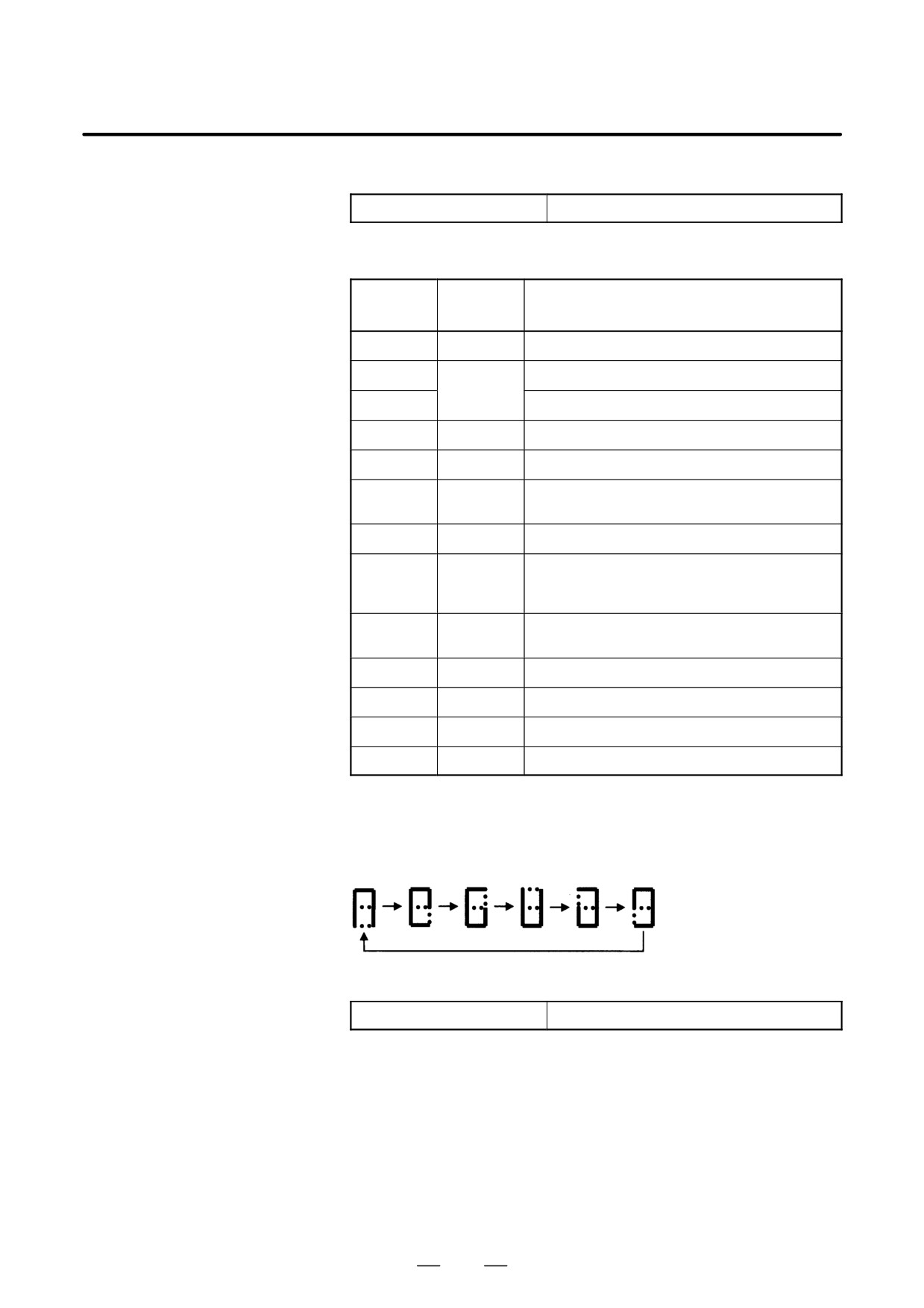
LED display during automatic operation start-up
While automatic operation start-up in progress signal STL (F0.5) is
held to 1, the 7-segment LED cyclically displays the following
patterns:
D LED display when a battery alarm occurs
ALARM Jjj
SRAM backup battery is weak.
285
4. STAND-ALONE TYPE i SERIES HARDWARE
B-63525EN/02
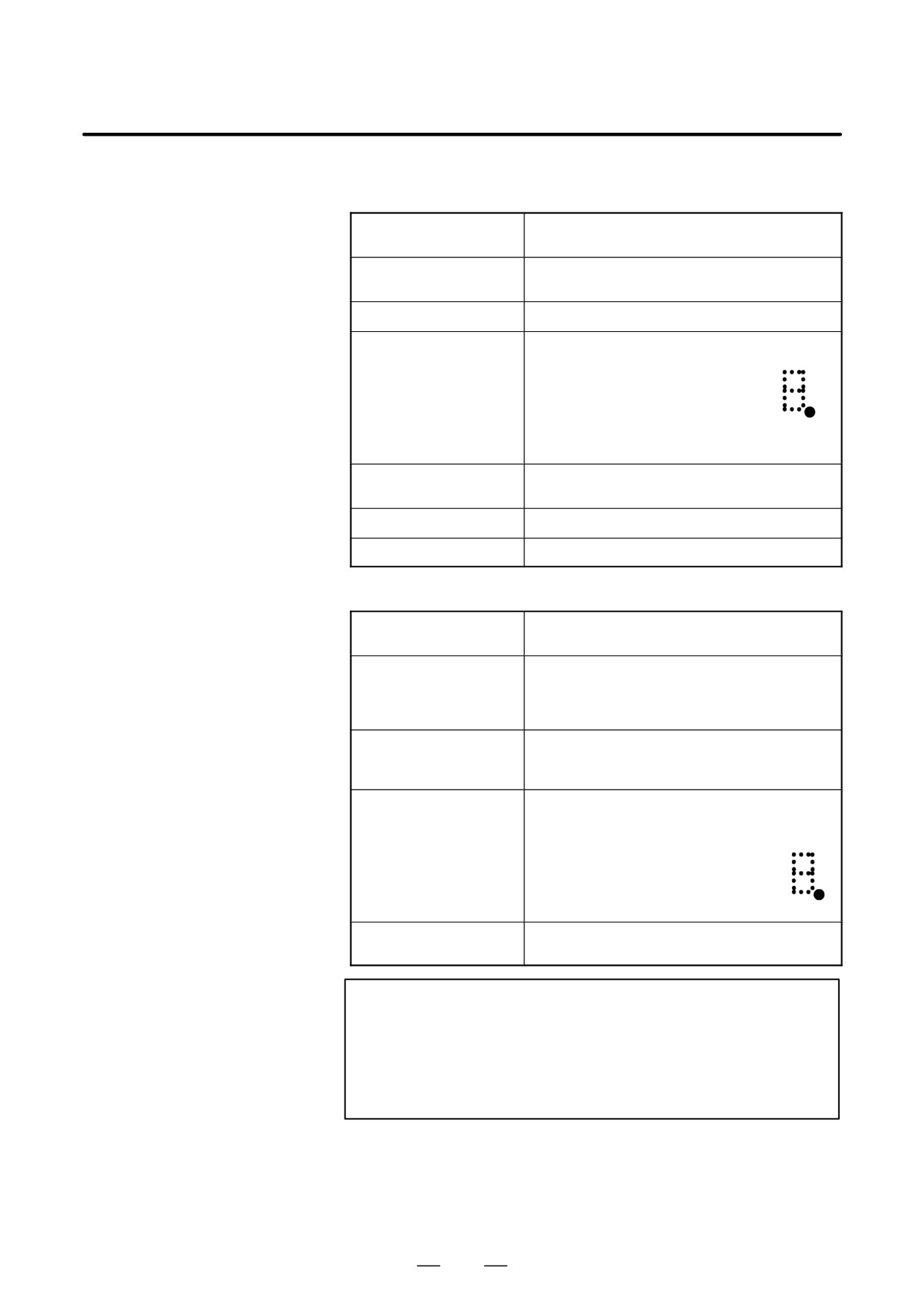
D LED display when a system alarm occurs j: Off J: On l: Blink
(if CPU card A20B-3300-031X is used)
ALARM jJj
System failure. The software detected an error and
stopped the system.
ALARM JJj
An error occurred on the local bus in the main CPU
board.
ALARM jjJ
System emergency. The hardware detected an error.
ALARM JlJ
A disconnection was found in the optical
fiber cable between the CNC and LCD.
Alternatively, a printed circuit board on the
LCD side is defective.
If a disconnection occurs, the dot of the
7-segment LED is also lit.
If a disconnection occurs, the display of the
LCD unit blinks.
ALARM jJJ
An SRAM parity error or SRAM ECC error was de-
tected.
ALARM JJJ
A DRAM parity was detected.
ALARM lll
A bus error occurred in the main CPU.
(If CPU card A20B-3300-029X is used)
ALARM jJj
System failure. The software detected an error and
stopped the system.
ALARM JJj
An error occurred on the local bus in the main CPU
board.
Alternatively, a bus error occurred in the main CPU.
Alternatively, a DRAM parity error was detected.
ALARM jjJ
System emergency. The hardware detected an error.
Alternatively, a bus error occurred in the main CPU.
Alternatively, a DRAM parity error was detected.
ALARM JjJ
A disconnection was found in the optical
fiber cable between the CNC and LCD.
Alternatively, a printed circuit board on the
LCD side is defective.
If a disconnection occurs, the dot of the
7-segment LED is also lit.
If a disconnection occurs, the display of the
LCD unit blinks.
ALARM jJJ
An SRAM parity error or SRAM ECC error was de-
tected.
NOTE
1
If any of the system alarms occurs, the hardware may be
defective.
2
If a disconnection is detected in the optical fiber cable
between CNC and LCD at power-up, the ALARM LEDs
alternately display these patterns: JjJ ³ jJj
286
4. STAND-ALONE TYPE i SERIES HARDWARE
B-63525EN/02
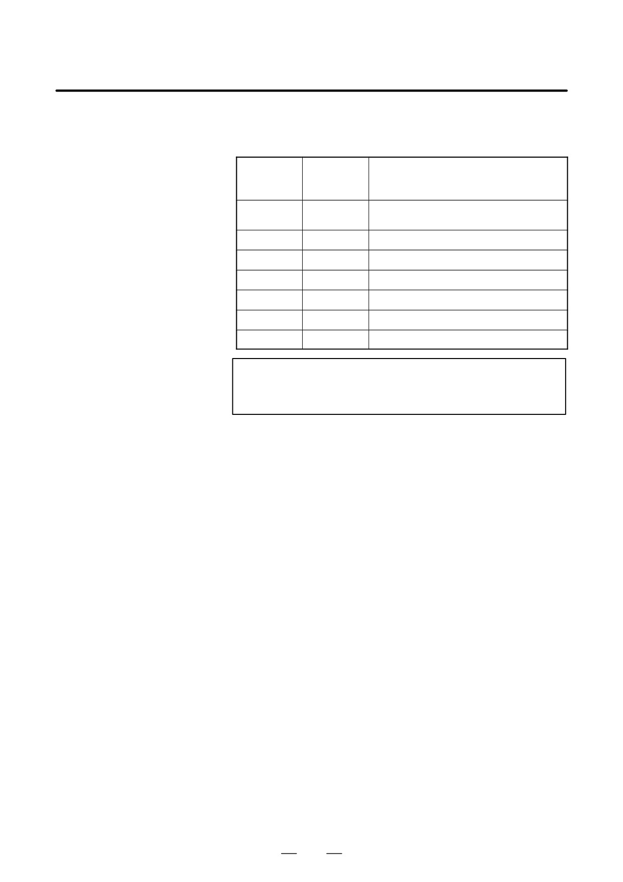
D 7-segment LED display when a system alarm occurs
If a system alarm occurs, a number blinks as shown below, depending
on the system alarm number.
System
7-segment
alarm num-
System alarm type
LED
ber
0
900 to 909
ROM parity alarm.
System ROM parity stored in FROM
1
910 to 919
SRAM or DRAM parity alarm
2
920 to 929
Servo alarm
3
930 to 949
CPU interrupt or SRAM ECC error
5
950 to 959
PMC system alarm
7
970 to 979
Bus error or non-maskable interrupt
8
Others
Other system alarms
NOTE
If any of the system alarms occurs, the hardware may be
defective.
287
4. STAND-ALONE TYPE i SERIES HARDWARE
B-63525EN/02
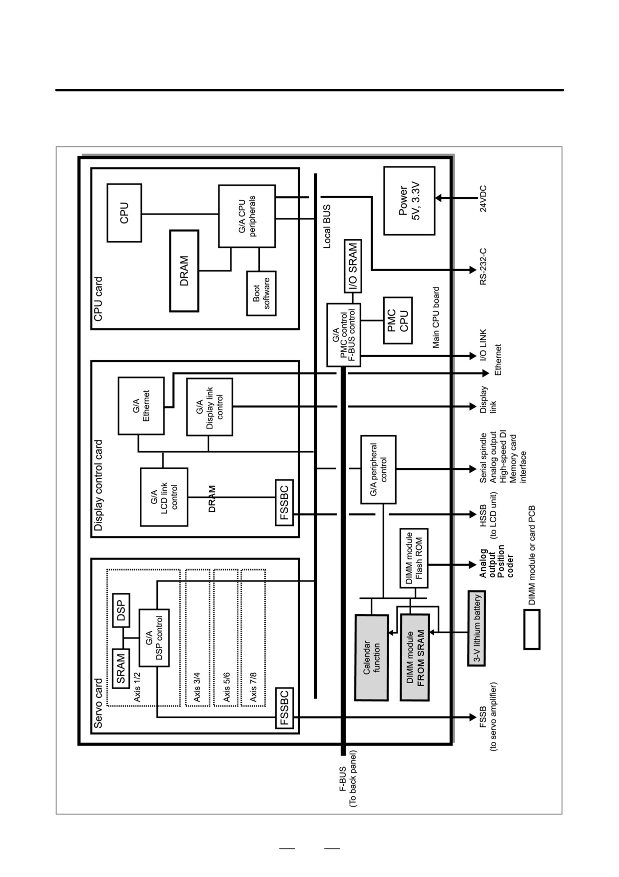
D Block diagram
288
4. STAND-ALONE TYPE i SERIES HARDWARE
B-63525EN/02
4.4.2
Sub-CPU Board
D Specifications
Item
Code
Sub-CPU board
A16B-2203-0751
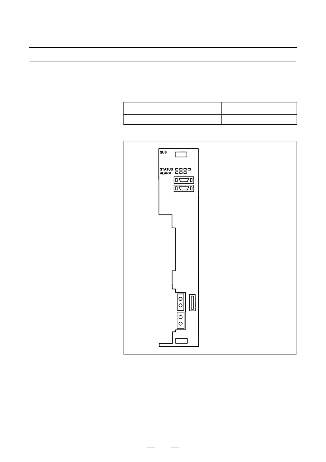
D Mounting positions of
connectors, LEDs, etc.
LED display
JA40-2: Analog output
JA41-2: Serial spindle/position coder
COP10A-2: FSSB2
CA69B: Servo check
COP10A-1: FSSB2
289
4. STAND-ALONE TYPE i SERIES HARDWARE
B-63525EN/02
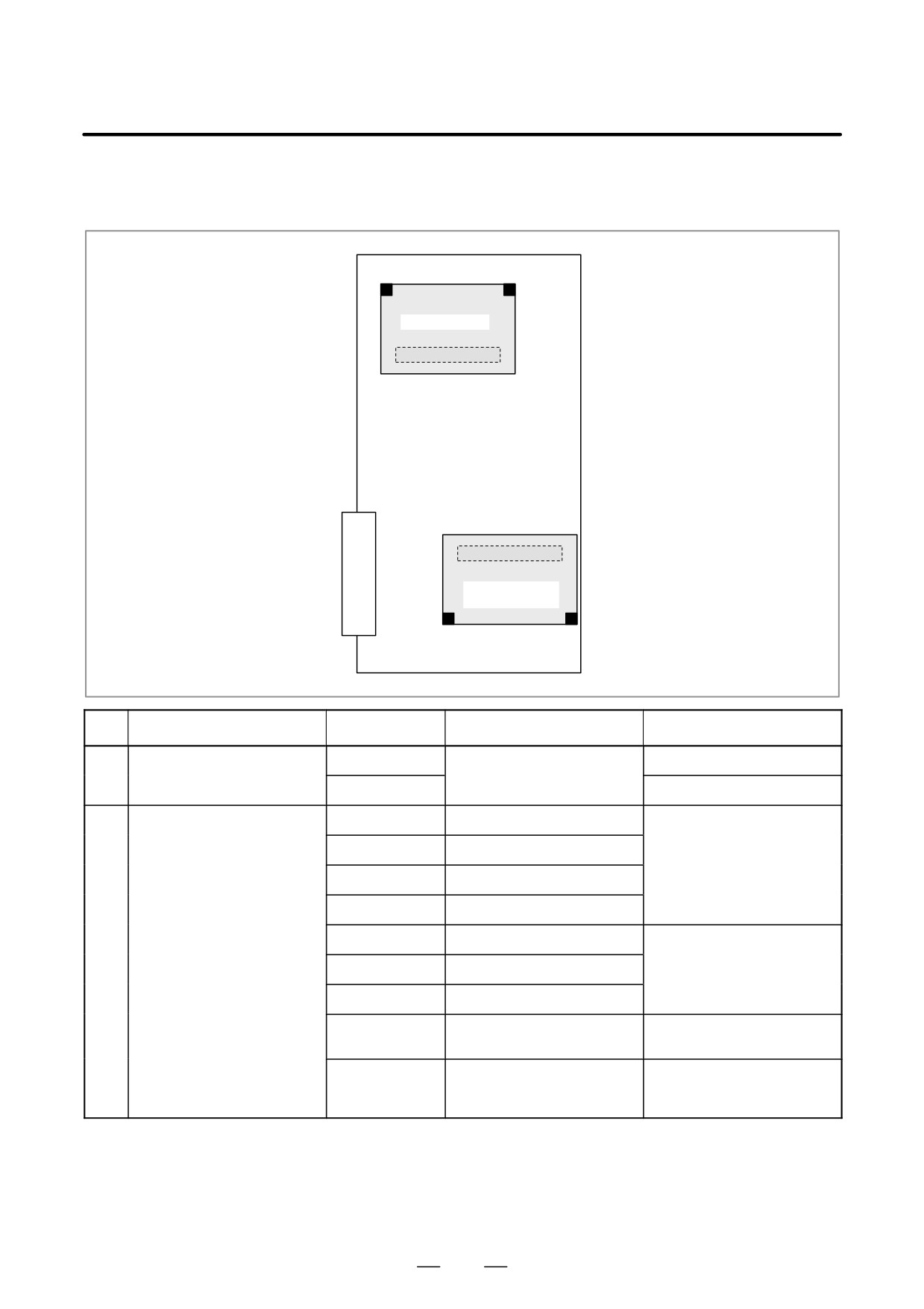
D Mounting positions of
cards and DIMM module
(1) CPU card
(2) Axis control
card
No.
Item
Code
Function
Remarks
(1)
CPU card
A20B-3300-0310
DRAM 16MB
A20B-3300-0311
DRAM 32MB
(2)
Axis control card
A20B-3300-0243
Axis control 2 axes
Servo software
Series 90B0
A20B-3300-0242
Axis control 4 axes
A20B-3300-0241
Axis control 6 axes
A20B-3300-0240
Axis control 8 axes
A20B-3300-0248
Axis control 4 axes
Servo software
Series 90B0
A20B-3300-0245
Axis control 6 axes
(High-speed HRV)
A20B-3300-0244
Axis control 8 axes
A20B-3300-0246
Learning controlled axis control
Servo software
Series 90B3/90B7
A20B-3300-0247
Learning controlled axis control
Servo software
Series 90B3/90B7
(High-speed HRV)
290
4. STAND-ALONE TYPE i SERIES HARDWARE
B-63525EN/02
D LED display
D LED display at power-up j: Off J: On
STATUS jjjj
Power off
STATUS JJJj
CPU not activated after power-up
STATUS Jjjj
Initialization completed, normal operation in progress
D LED display when a system alarm occurs j: Off J: On l: Blink
ALARM jJj
Servo alarm
ALARM Jjj
A DRAM parity error was detected.
ALARM ljj
A bus error occurred in a sub-CPU.
NOTE
If any of the system alarms occurs, the hardware may be
defective.
291
4. STAND-ALONE TYPE i SERIES HARDWARE
B-63525EN/02
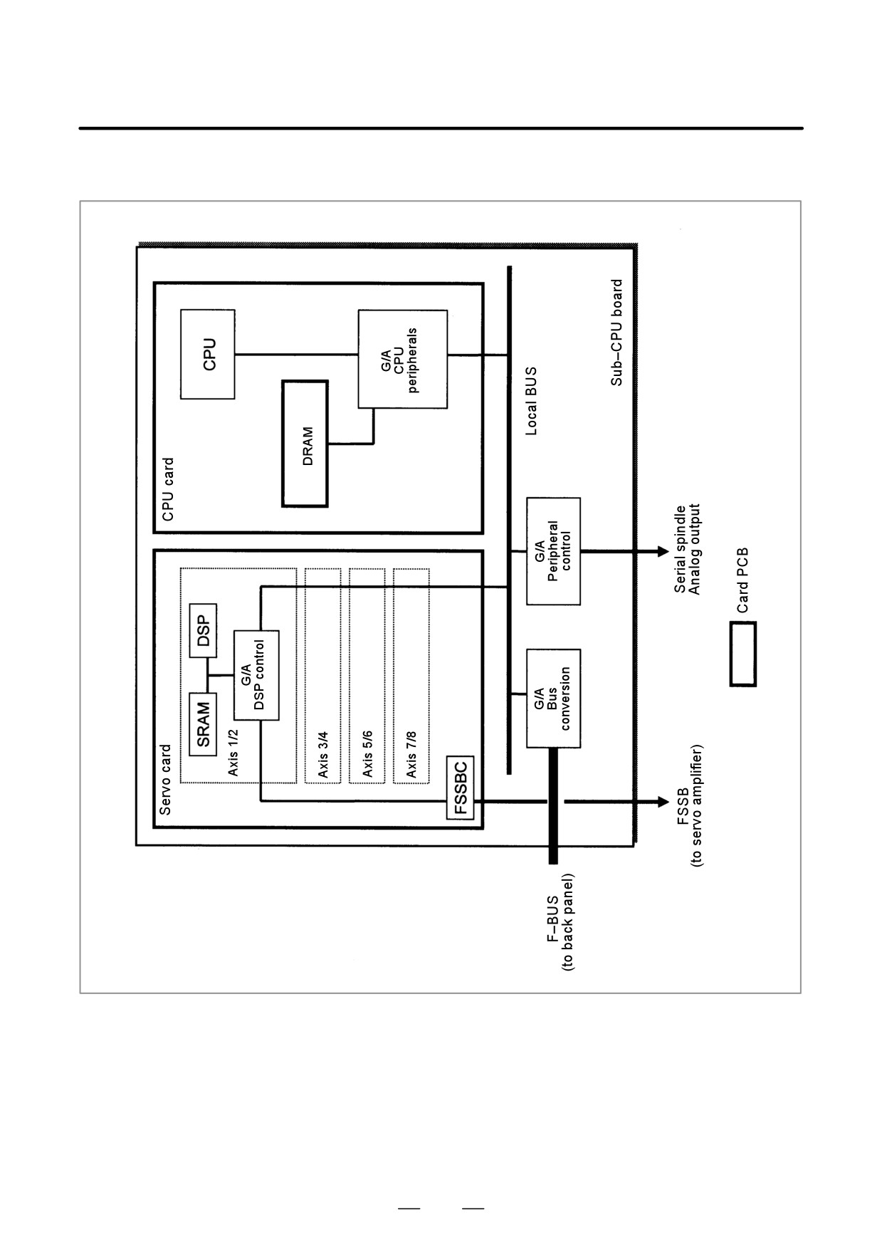
D Block diagram
292
4. STAND-ALONE TYPE i SERIES HARDWARE
B-63525EN/02
4.4.3
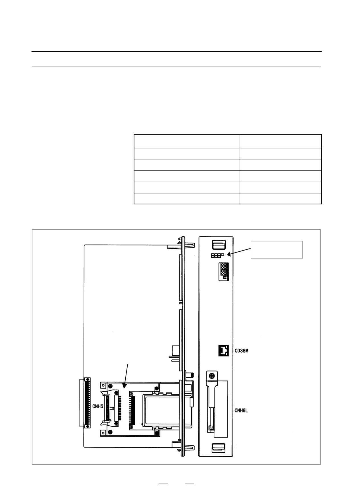
The RISC function and data server function are provided on a single
option board. If the RISC function alone is needed, a RISC board is used.
RISC Board, Data
If just the data server function is needed, a data server board is used. If
Server Board, RISC +
the two functions are needed, a RISC + data server board is used.
Data Server Board
If the data server function is used, an ATA card adapter is mounted on the
board. This board and ATA card adapter are connected by a flat cable.
D Specifications
Item
Code
RISC + Data server board
A16B-3200-0390
RISC board
A16B-3200-0391
Data server board
A16B-3200-0352
CPU card
A20B-3300-0102
ATA card adapter
A20B-2100-0500
D Mounting positions of
connectors, LEDs, etc.
A RISC board has
just these LEDs.
ATA card adapter
293
4. STAND-ALONE TYPE i SERIES HARDWARE
B-63525EN/02
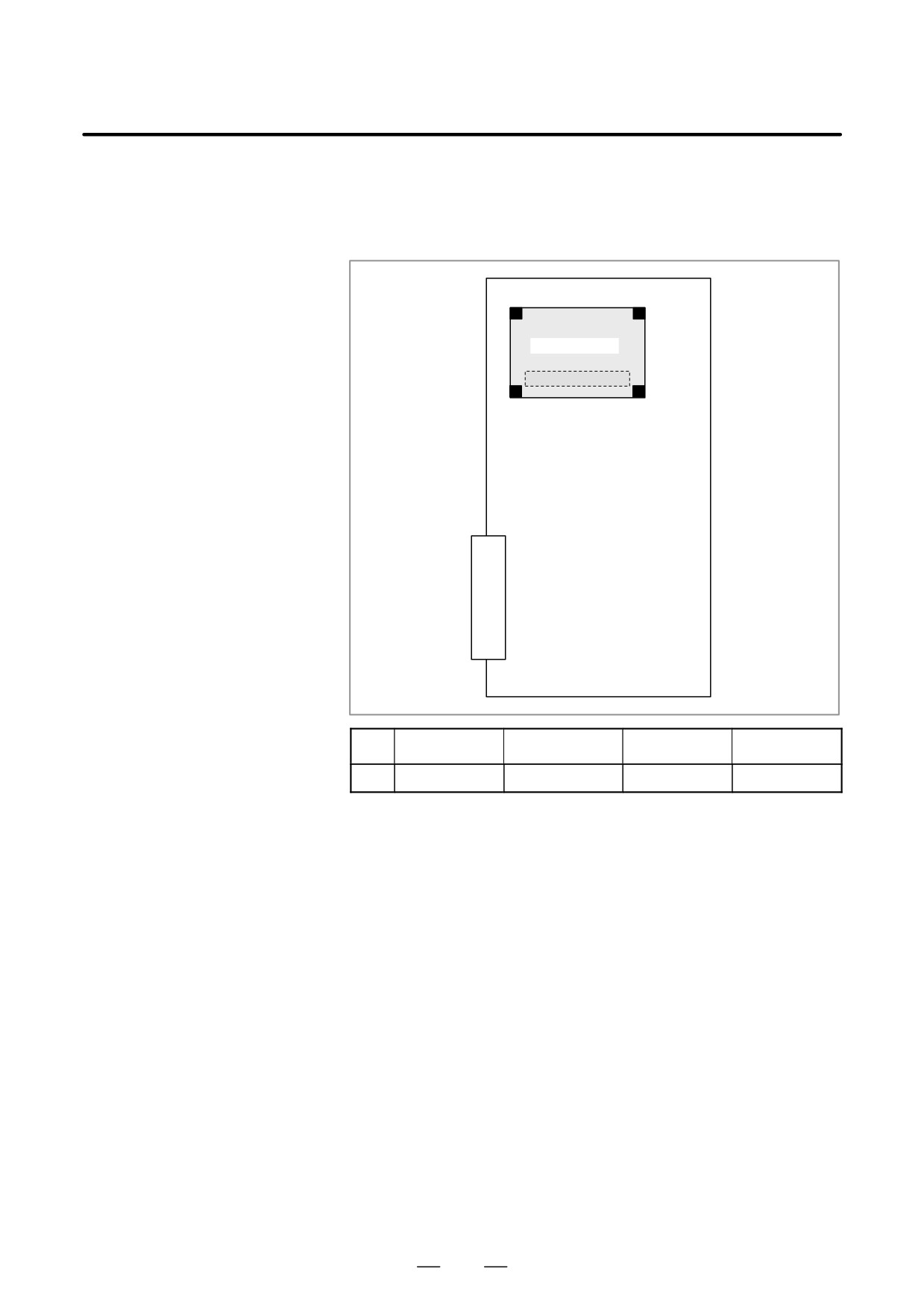
D Mounting position of
card (For RISC card,
RISC+DATA SERVER
board)
(1) CPU card
No.
Item
Code
Function
Remarks
(1)
CPU card
A20B-3300-0102
Standard type
294
4. STAND-ALONE TYPE i SERIES HARDWARE
B-63525EN/02
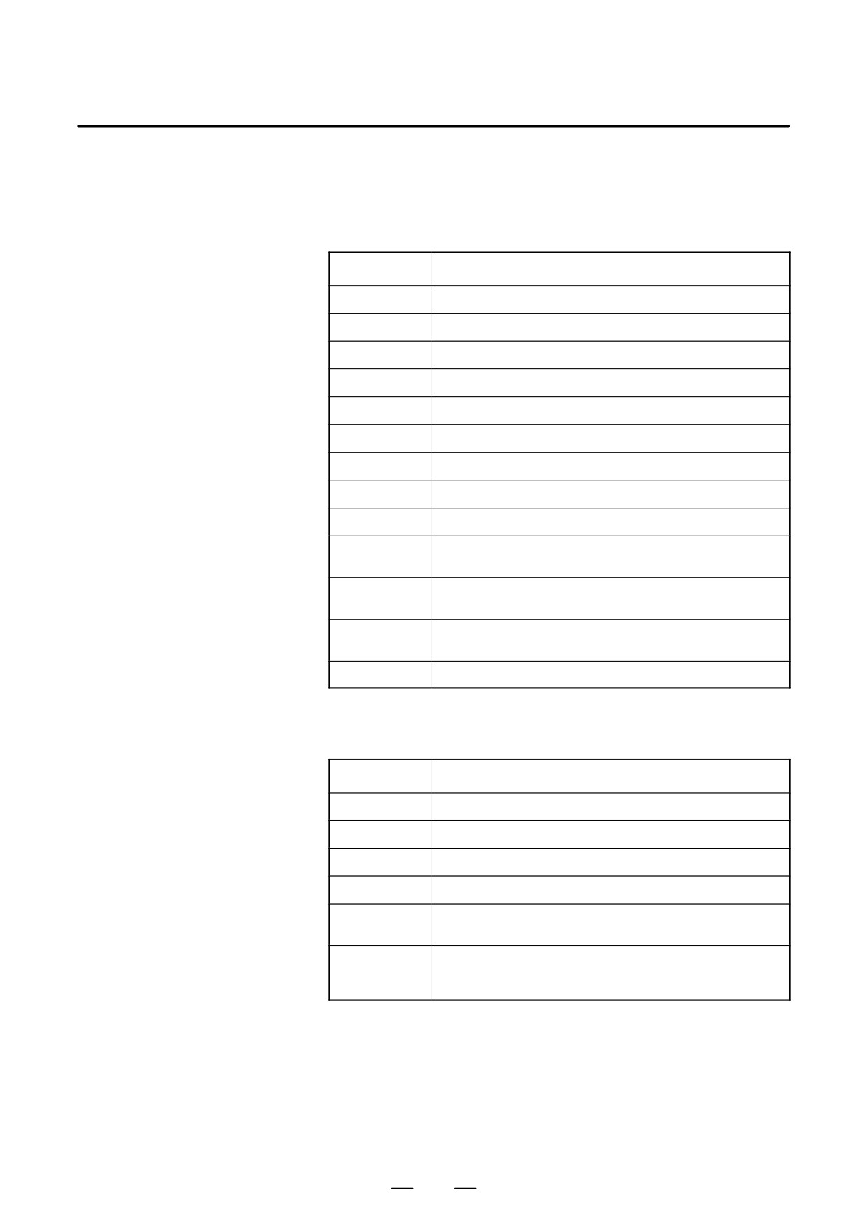
D LED display of the RISC
The RISC function uses the green STATUS LEDs and red ALARM LEDs
function
in the upper part of the face plate. The red ALARM LEDs are used also
by the data server function.
<1> Status LED indication (green LED turned on)
Alarm LED
State
jjjj
The power is not turned on.
Jjjj
Waiting for the CNC (1) (Check the cause of the CNC.)
jJjj
Module ID error (Replace the printed circuit board or FROM.)
JJjj
Waiting for the CNC (5) (Check the cause of the CNC.)
jjJj
ROM test error (Replace the printed circuit board or FROM.)
JjJj
Waiting for the CNC (3) (Check the cause of the CNC.)
JJJj
System error (Replace the printed circuit board or FROM.)
jjjJ
RAM test error (Replace the printed circuit board.)
JjjJ
Waiting for the CNC (2) (Check the cause of the CNC.)
Parameter error (Replace the printed circuit board or FROM.)
jJjJ
(B437 series only)
DRAM test error/waiting for interrupt at interpolation cycles (Replace
jjJJ
the printed circuit board.)
Waiting for the CNC (4) (Check the cause of the CNC.) (B451 series
JjJJ
only)
JJJJ
The power is turned on, but the processor is not started yet.
J : ON j : OFF
<2> Status LED indication (green LED blinking)
Alarm LED
State
Ljjj
Command being executed (reset)
jLLj
Command being executed (preprocessing, distribution processing)
jjjL
Waiting for a command
jLjL
Waiting for NC statement input
LLjL
Command being executed (parameter modification)
(B437 series only)
jjLL
Automatic operation is not started yet. (Replace the printed circuit
board.)
(B451 series only)
L : Blinking j
: OFF
295
4. STAND-ALONE TYPE i SERIES HARDWARE
B-63525EN/02
<3> Alarm LED indication (red LED)
Alarm LED
State
JjJ
The power supply for the processor core on the RISC board is de-
fective.
jjJ
A DRAM parity error occurred on the CPU card.
JJj
System emergency
jJj
(Reserved)
J : ON j : OFF
NOTE
The LEDs display any other pattern if an error occurs in the
data server option.
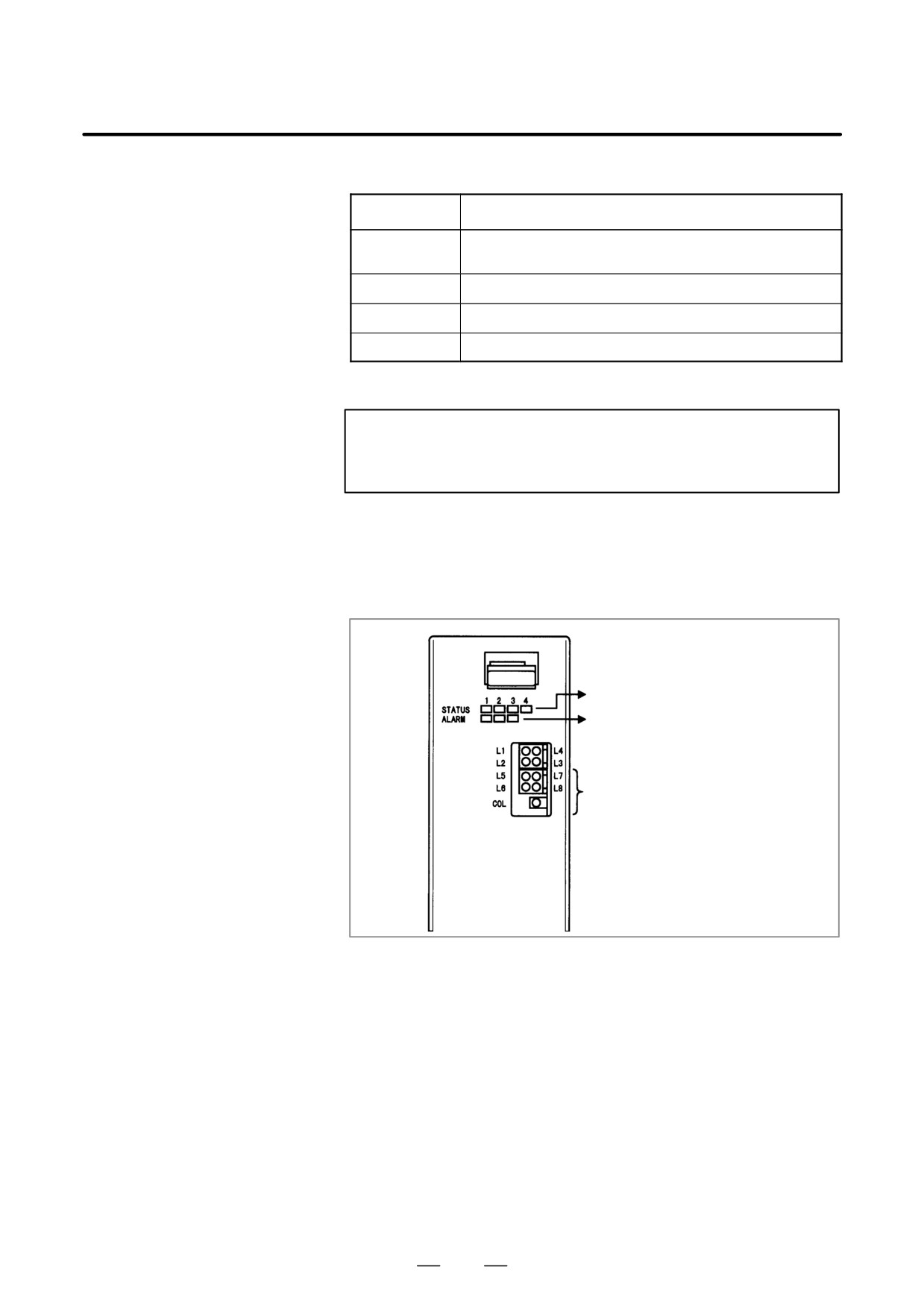
D LED display of the data
The data server board function uses four green STATUS LEDs for status
server function
display and red LEDs for alarm display (used also by the RISC function).
The function uses other green LEDs and a single red LED for
communication status display.
For RISC status
For RISC and data server
For data server status
For communication status
296
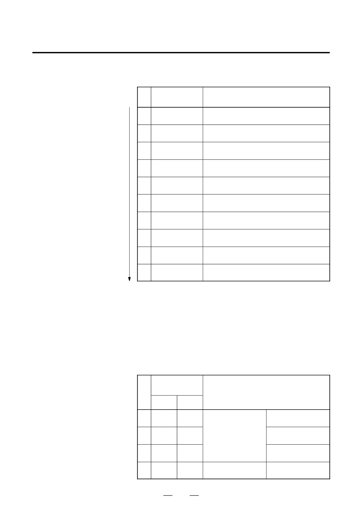
4. STAND-ALONE TYPE i SERIES HARDWARE
B-63525EN/02
LED status transition at power-up
LED statuses f: Off F: On l: Blink Z: Don’t care
LED display
No.
Board status
(L1 to L4)
1
ff
Power off
ff
2
FF
Initial state immediately after power-up
FF
3
fF
MPU initialization completed
FF
4
fF
Firmware downloading completed
fF
5
fF
Control transferred to OS
ff
6
Ff
OS PHASE 1
FF
7
ff
OS PHASE 2
FF
8
Ff
OS PHASE 3
fF
9
ff
OS PHASE 4
fF
10
lf
Activation completed
ff
If the board is normally activated, the LEDs display the pattern of No.10
and keep this state until an error is detected.
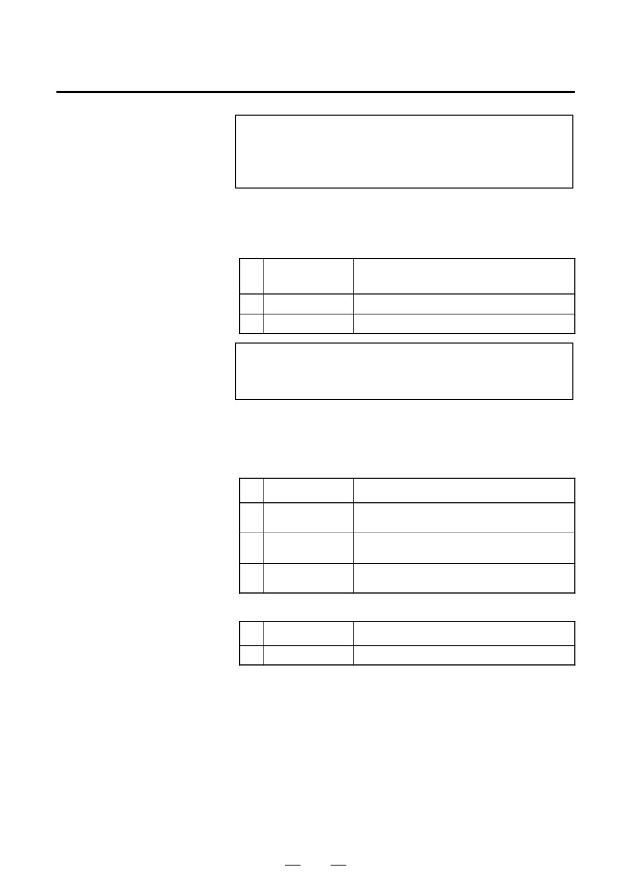
LED display when an error occurs (STATUS L1 to L4)
The STATUS LEDs alternately display the LONG and SHORT patterns.
The LONG pattern is held longer than the SHORT pattern.
LED statuses
f: Off F: On
STATUS LED
indication
No.
Ethernet/data server board state
LONG
SHORT
fF
Ff
1
System reset
ff
ff
fF
ff
Failure caused by this
2
Machine check
ff
Ff
board
fF
Ff
3
DRAM parity alarm
fF
ff
fF
ff
Failure caused by another
4
NMI of another module
fF
Ff
board
297
4. STAND-ALONE TYPE i SERIES HARDWARE
B-63525EN/02
NOTE
If an error, indicated by repeatedly flashing a LONG and
SHORT combination other than the above, occurs, contact
FANUC.
LED display when an error occurs (ALARM)
LED statuses
j: Off J: On
LED display
No.
Board status
123
1
jJJ
An MPU transfer error occurred.
2
JJJ
A parity error occurred in the main memory.
NOTE
Any other pattern is displayed if an error occurs in the RISC
option.
LED display for communication status
Communication status (L5 to L8)
LED statuses
f: Off F: On l: Blink Z: Don’t care
No.
LED display
Communication status
1
ZZ
Data transmission in progress
FZ
2
ZZ
Data reception in progress
ZF
3
ZF
Hub normally connected
ZZ
Communication status (COL)
No.
LED display
Communication status
1
F
Lit when a data collision occurs.
COL: This LED is frequently lit if the traffic of Ethernet communication is large
or if the peripheral noise is large.
298
4. STAND-ALONE TYPE i SERIES HARDWARE
B-63525EN/02
4.4.4
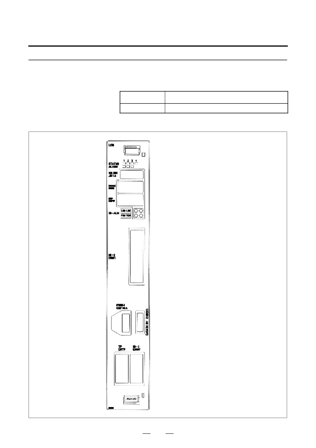
Loader Control Board
D Specification
Name
Specification
Loader Control Board
A16B-2203-0740
D Connector location
LED display
JD1A : FANUC I/O LINK
CNBK : Brake drive output
CNPW : Emergency stop control
LED display for I/O alarm
CRM1 : DI/DO for loader main body
COP10A : FSSB
CA69D : Servo check
CNTP : DI/DO for loader operator’s panel
CNWF : DI/DO for workpiece feeder
299
4. STAND-ALONE TYPE i SERIES HARDWARE
B-63525EN/02
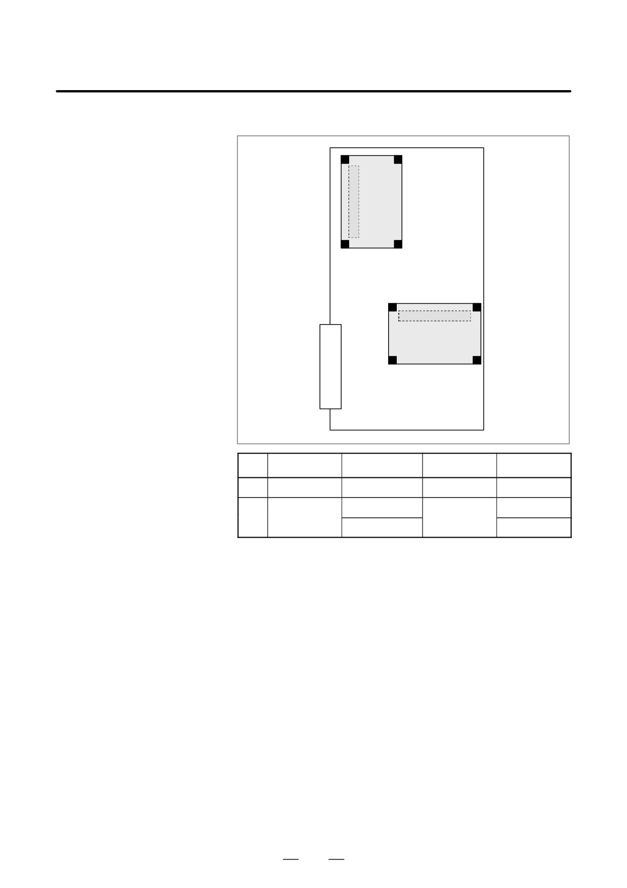
D Card location
(1) CPU card
(2) Axis control card
No.
Item
Code
Function
Remarks
(1)
CPU card
A20B-3300-0291
CNC control
A20B-3300-0032
4 axes
(2)
Axis control card
Axis control
A20B-3300-0033
2 axes
300
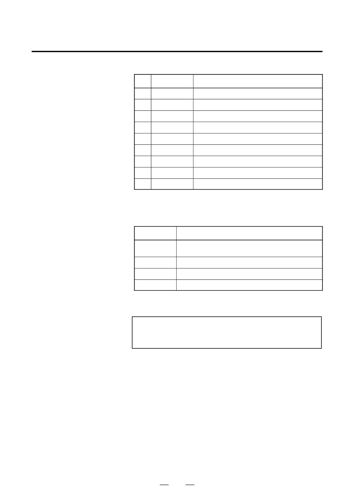
4. STAND-ALONE TYPE i SERIES HARDWARE
B-63525EN/02
- LED Display Transition at Power-up
NO.
LED display
NC Status
1
STATUS:jjjj
Power off
2
STATUS:JJJJ
Startup status immediately after power is turned on
3
STATUS:jJJJ
RAM initialized
4
STATUS:JjJJ
Software ID set; keys initialized
5
STATUS:jjJJ
Waiting for completion of software initialization 1
6
STATUS:JJjJ
Waiting for completion of software initialization 2
7
STATUS:jJjJ
Position coder initialized, etc.
8
STATUS:jJJj
Waiting for digital servo initialization
9
STATUS:Jjjj
Initialization completed (steady state)
J : ON j : OFF
The STATUS LEDs are green.
- LED Display when an Error occurs
LED display
Description
ALM:jJj
System failure occurred.
The software detects the error and stops the system.
ALM:JJj
Error in Local bus on the loader control board occurred.
ALM:jjJ
System emergency occurred. Hardware detects the error.
ALM:jJJ
SRAM parity error on the loader control board occurred.
J : ON j : OFF
The ALARM LEDs are red.
NOTE
When two or more error occur simultaneously, the LED
display shows the state of low side on the table above.
301