FANUC Series 16i/160i/160is-MODEL B, Series 18i/180i/180is-MODEL B, Series 21i/210i/210is-MODEL B. MAINTENANCE MANAUL - page 9
2.
LCD-MOUNTED TYPE i SERIES
HARDWARE
B-63525EN/02
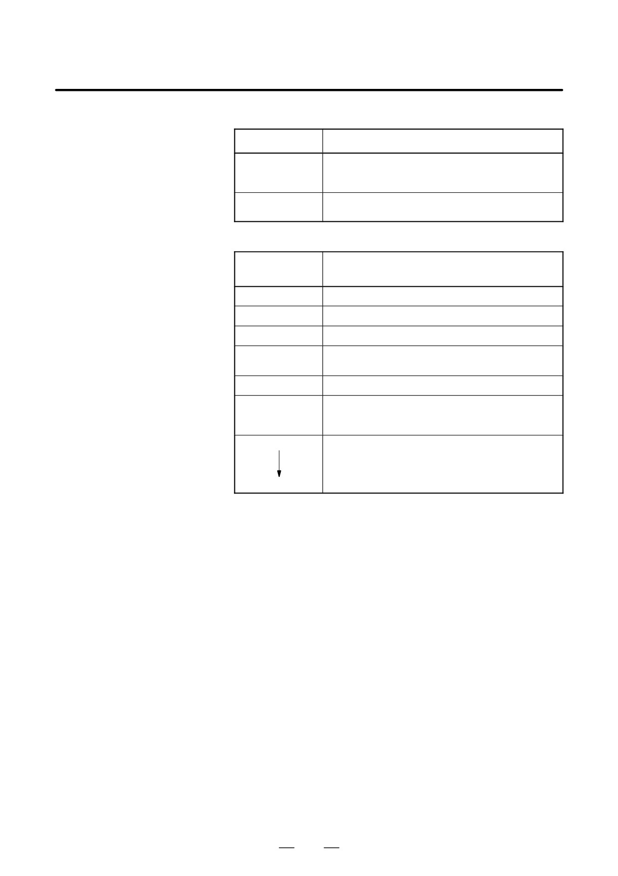
(1) Hardware control LEDs
LED No.
Meaning
LED5
Lights when the CPU on the FANUC I/O Link-II board is run-
ning. When the LED is off, it means that the CPU has been
reset.
LED6
Lights when a DRAM parity error is detected.
It is likely that the hardware is defective.
(2) Soft control LEDs
Status LED
Meaning
(ST4 to 1)
JJJJ
Immediately after power is switched on.
JJjj
Communication board being initialized.
ljjj
DI/DO data is being transferred normally.
jjjJ
A RAM parity error has occurred.
It is likely that the hardware is defective.
jjJJ
An F-BUS error has occurred.
jjJj
An F-BUS system emergency condition has occurred. Alterna-
tively, a communication error (FCS error, command error, frame
length error, response time-out, etc.) has occurred.
ljJj
A communication error has occurred, resulting in error log being
stored. Communication with a slave station has restarted.
LED2 goes off when a log command (monitor function) is used.
It goes off also when the communication error log is erased
ljjj
using a clear command.
J: On j: Off l: Blinking
212
2. LCD-MOUNTED TYPE i SERIES
B-63525EN/02
HARDWARE
2.4.10
PROFIBUS Board
Name
Specification
PROFIBUS board (master function)
A20B-8100-0430
Add-on board (slave function)
A20B-2100-0430
NOTE
The PROFIBUS board cannot fit into any of the following
slots.
· Center slot of a unit with 3 option slots
· Option slot farthest from the LCD in a unit with 4 option
slots
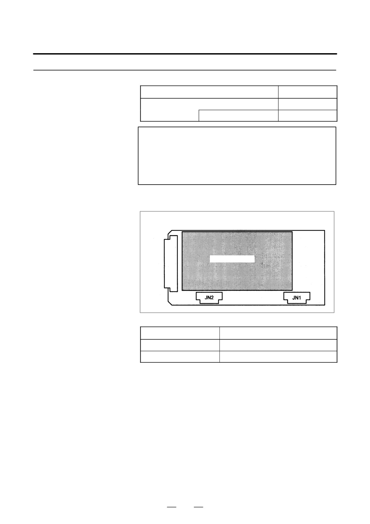
D Connector location
JNA
F-BUS backplane connector
Add-on board
Connector number
Application
JN1
Adapter unit interface for master station
JN2
Adapter unit interface for slave station
D Card location
No card is mounted on the PROFIBUS board.
213
2. LCD-MOUNTED TYPE i SERIES
HARDWARE
B-63525EN/02
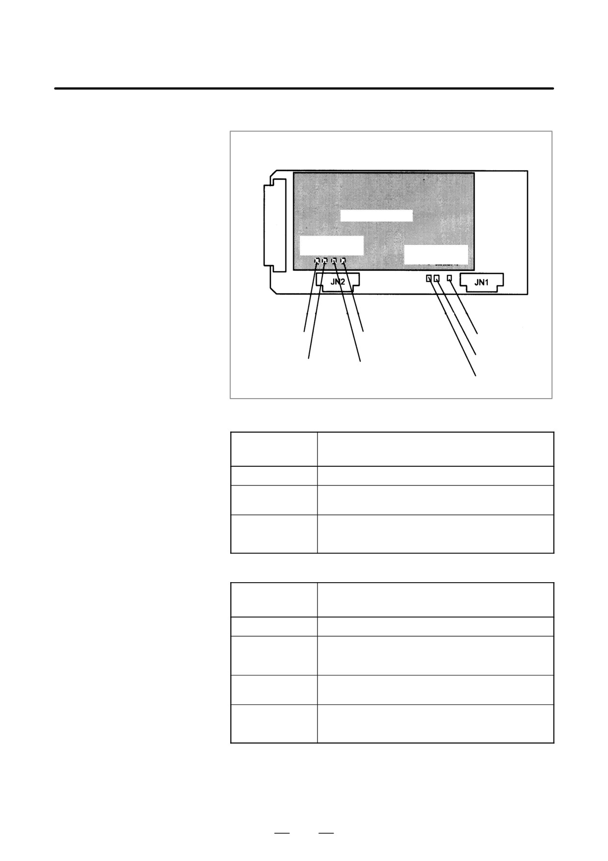
D LED indication
JNA
F-BUS backplane connector
ADD-ON board
LEDs for slave
function
LEDs for master
function
LED1 (green)
LEDB (red)
LEDB (red)
LED2 (green)
LED2
(green)
LED3 (green)
LED1 (green)
(1) LEDs for master function
LED No.
Meaning
(abbreviation)
LED1 (CPU)
Lights to indicate the CPU for the master function is running.
LED2 (TOKEN)
Lights when the communication LSI (ASPC2) has a token
(right to transmit).
LEDB (PALM)
Lights when a memory parity alarm occurs in the master
function circuit.
It is likely that the hardware is defective.
(2) LEDs for slave function (mounted on the add-on board)
LED No.
Meaning
(abbreviation)
LED1 (CPU)
Lights to indicate the CPU for the slave function is running.
LED2 (COMM)
Lights when PROFIBUS communication starts. It remains to
be on after the PROFIBUS communication is suspended,
however.
LED3 (RUN)
Lights to indicate that PROFIBUS communication is being
performed normally.
LEDB (PALM)
Lights when a memory parity alarm occurs in the slave function
circuit.
It is likely that the hardware is defective.
214
2. LCD-MOUNTED TYPE i SERIES
B-63525EN/02
HARDWARE
2.4.11
Ethernet Board
Name
Specification
Ethernet board
A20B-8100-0271
NOTE
The Ethernet board cannot fit into the option slot nearest to
the LCD.
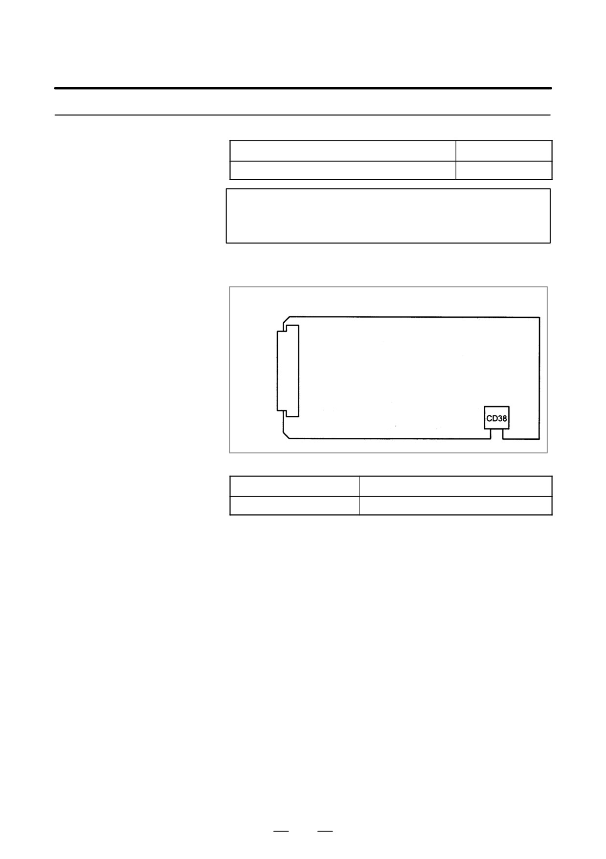
D Connector location
JNA
F-BUS backplane connector
Connector number
Application
CD38
10BASE-T Ethernet interface
D Card location
No card is mounted on the Ethernet board.
215
2. LCD-MOUNTED TYPE i SERIES
HARDWARE
B-63525EN/02
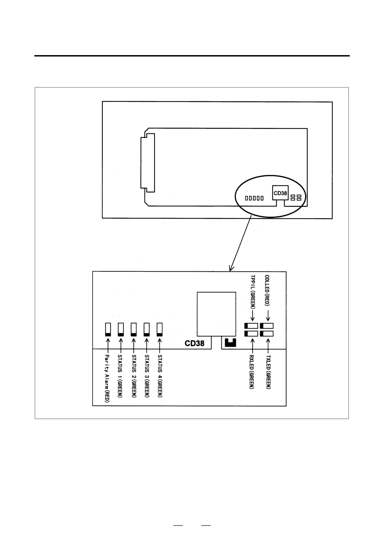
D LED indication
JNA
F-BUS backplane connector
Detailed LED diagram
216
2. LCD-MOUNTED TYPE i SERIES
B-63525EN/02
HARDWARE
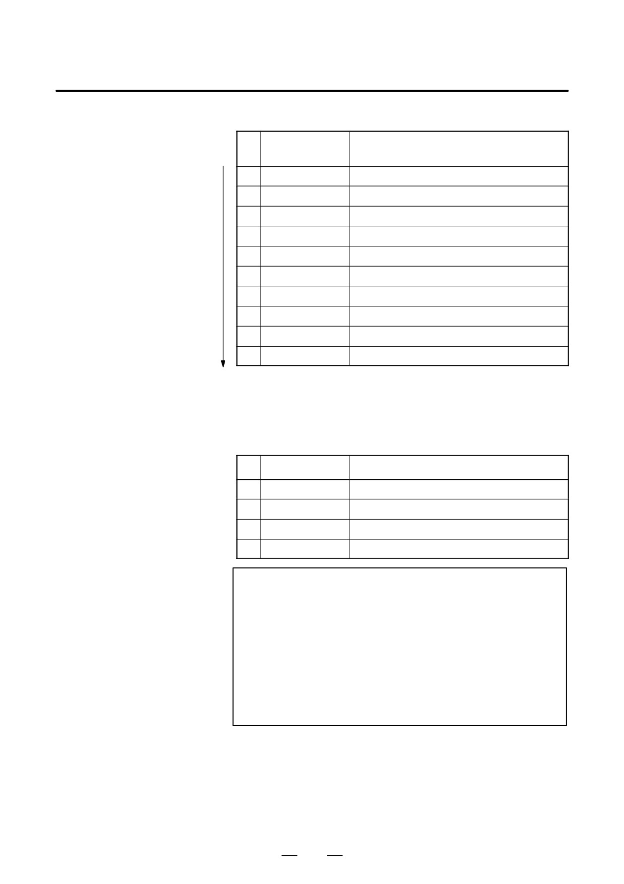
LED indication transition at power-on time
LED indication
No.
Ethernet board status
1234
1
STATUS jjjj
Power off
2
STATUS JJJJ
Initial status immediately after power is switched on.
3
STATUS jJJJ
MPU initialization completed.
4
STATUS jjJJ
Firmware download completed.
5
STATUS jjjJ
Control passed to the OS.
6
STATUS JJJj
OS PHASE 1
7
STATUS jJJj
OS PHASE 2
8
STATUS JjJj
OS PHASE 3
9
STATUS jjJj
OS PHASE 4
10
STATUS ljjj
Start sequence completed.
When the Ethernet board is started normally, the STATUS LEDs light as
shown at No. 10. This condition is preserved unless an abnormal
condition occurs.
Communication status LED indication
No.
LED indication
Ethernet communication status
1
RXLED
J
Lights during data reception.
2
TXLED
J
Lights during data transmission.
3
TPPIL
J
Lights to indicate a normal connection with the hub.
4
COLLED
J
Lights to indicate a data collision.
NOTE
TPPIL: If this LED is off, communication does not occur.
It is likely that the Ethernet board is not
connected with the hub normally. The LED does
not light also when the power to the hub is off. It
remains to be on when the Ethernet board is
connected to the hub normally.
COLLED: This LED lights frequently if Ethernet
communication
traffic
(amount
of
communication) is heavy. It also lights frequently
if noise in the surrounding is high.
217
2.
LCD-MOUNTED TYPE i SERIES
HARDWARE
B-63525EN/02
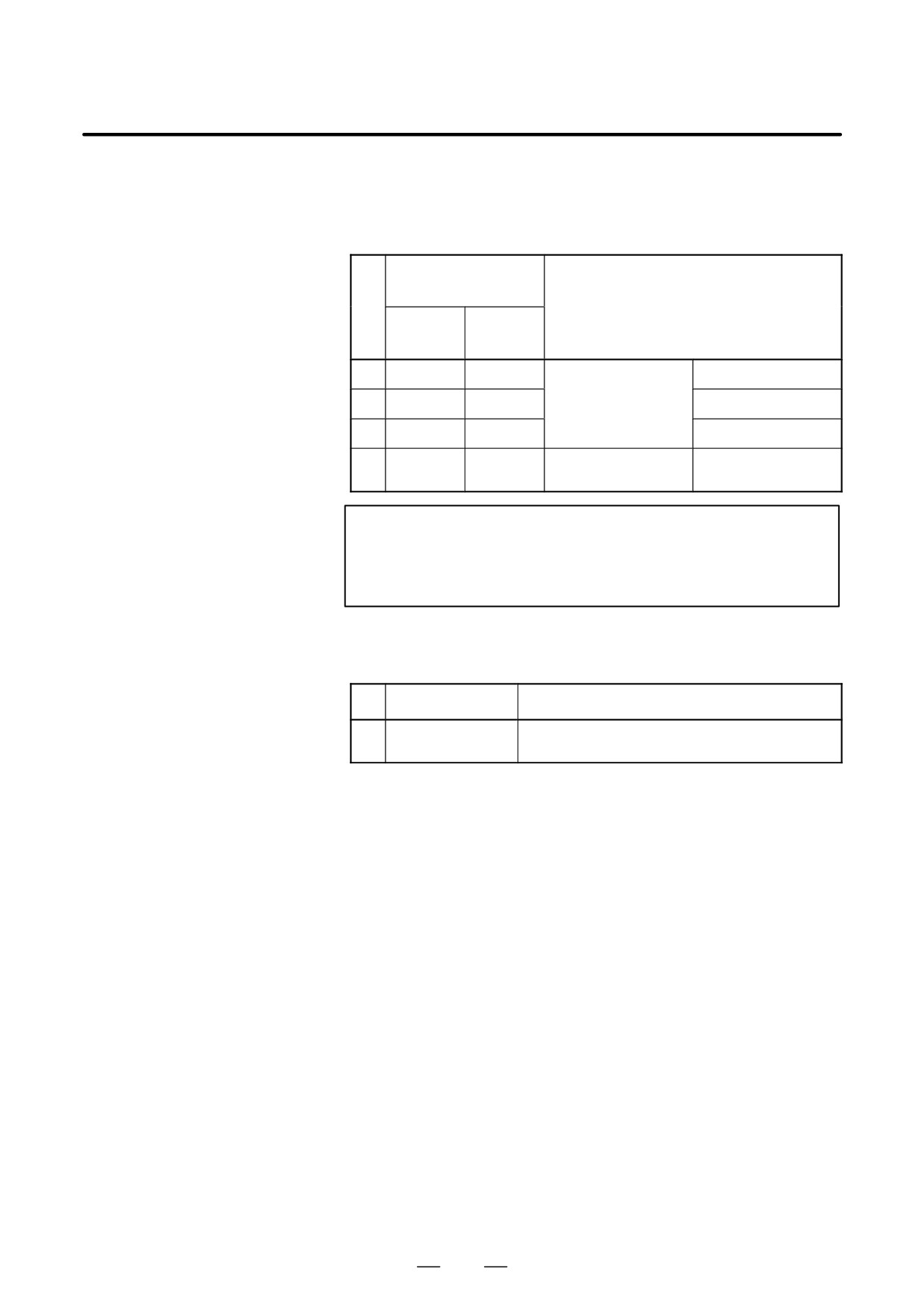
LED indication (STATUS) at error occurrence
The STATUS LEDs repeat LONG and SHORT patterns. The LONG and
SHORT patterns correspond to long and short lighting intervals,
respectively.
STATUS LED
indication
No.
Ethernet/data server board state
LONG
SHORT
1234
1234
1
jjjJ
Jjjj
Failure caused by this
System reset
board.
2
jjjJ
jJjj
Machine check
3
jjJJ
Jjjj
DRAM parity alarm
4
jjJJ
jJjj
Failure caused by anoth-
NMI of another module
er board.
NOTE
If an error, indicated by repeatedly flashing a LONG and
SHORT combination other than the above, occurs, contact
FANUC.
LED indication (ALARM) at error occurrence
No.
LED indication
Ethernet board status
1
Parity Alarm
J
A parity error has occurred in main memory.
It is likely that the hardware is defective.
218
2. LCD-MOUNTED TYPE i SERIES
B-63525EN/02
HARDWARE
2.4.12
DeviceNet Interface
Board
Name
Specification
DeviceNet interface board
A20B-8001-0880
NOTE
The DeviceNet board cannot fit into the center option slot of
a unit with 3 option slots
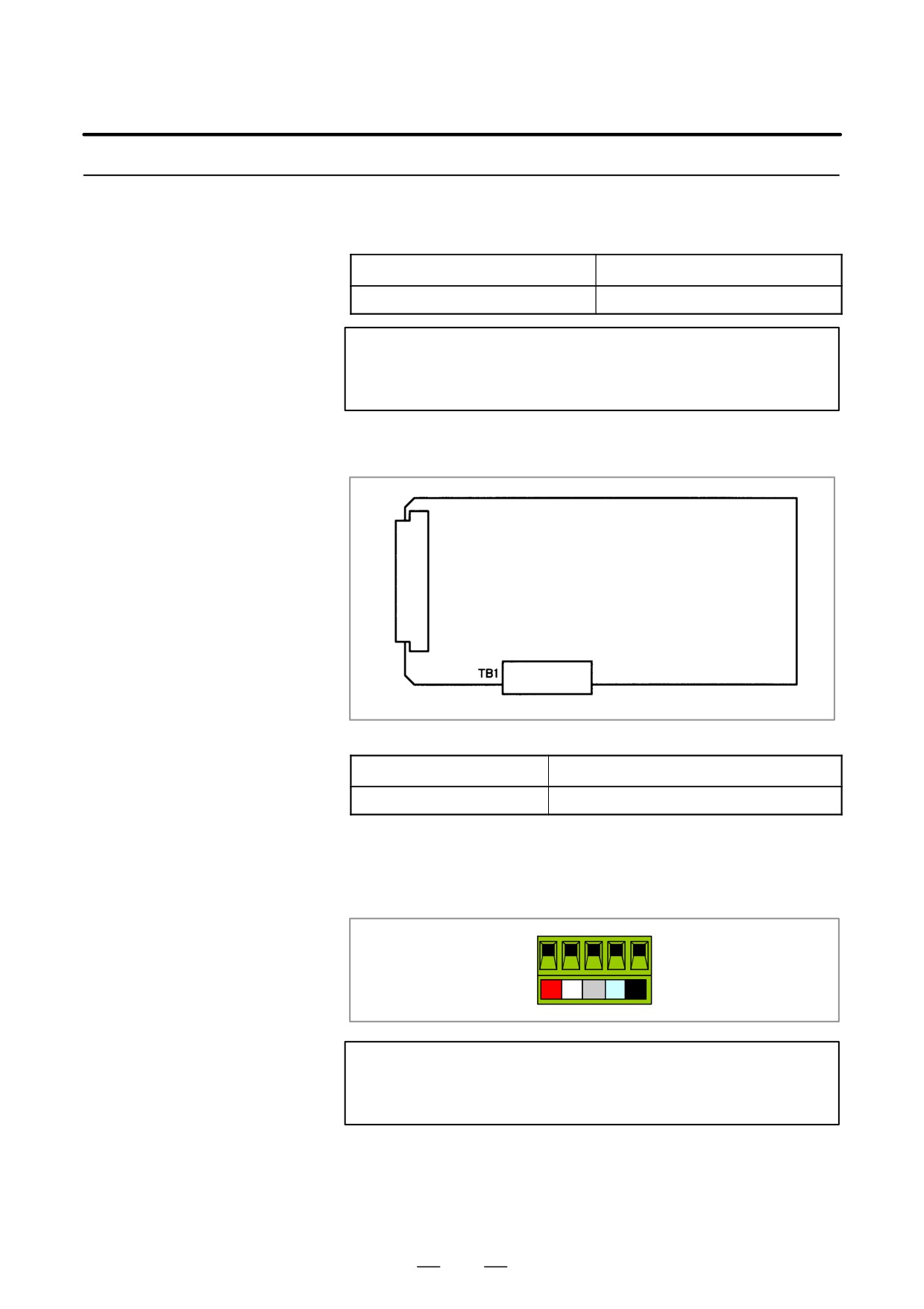
D Connector mounting
location
JNA
F-BUS backplane connector
Connector number
Application
TB1
DeviceNet interface
The terminal plate can be removed from the DeviceNet board interface
connector with the cable still connected. Remove the terminal plate by
pulling it towards you.
NOTE
The DeviceNet board cannot be removed unless the
connector ’s terminal plate has been removed first.
219
2. LCD-MOUNTED TYPE i SERIES
HARDWARE
B-63525EN/02
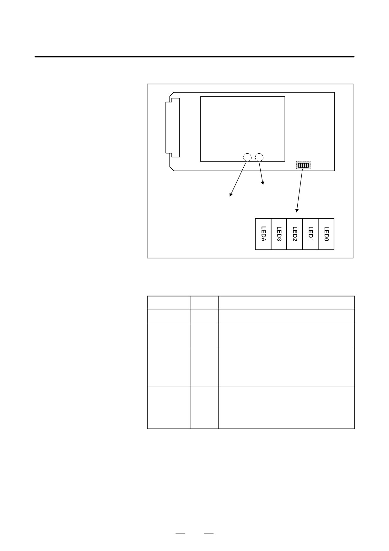
D LED display
Daughter board
HEALTH
NS
NS and HEALTH are mounted on the back of the daughter board.
LED indication
Name
Color
Description
LED0 to 3
Green
No special meaning
LEDA
Red
This LED glows when something unusual occurs in the
internal daughter board. At power-up, the LED does not
glow. If this LED glows, replace the DeviceNet board.
NS
Red/
DeviceNet module/network status LED. The LED indi-
green
cates whether the DeviceNet board is turned on or
whether DeviceNet communication is normally per-
formed. For the meaning of this LED indication, refer to
the specifications supplied by ODVA.
HEALTH
Red/
This LED indicates the status of the daughter board. At
green
power-up, this LED glows in red. When the firmware is
loaded to the internal daughter board, the LED turns
green. Then, if something unusual occurs in the daughter
board, the LED turns red. If the LED does not turn green,
replace the DeviceNet board.
220
2. LCD-MOUNTED TYPE i SERIES
B-63525EN/02
HARDWARE
2.5
LIST OF UNITS AND
PRINTED CIRCUIT
BOARDS
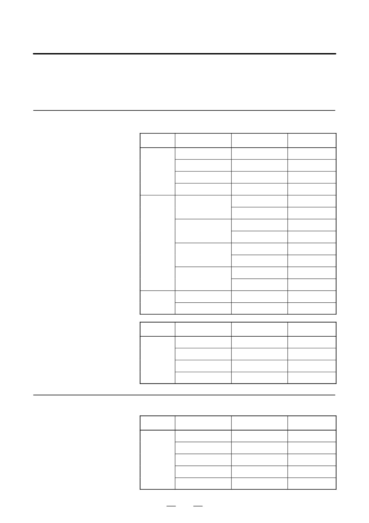
2.5.1
Basic Unit
Model
Name
Drawing number
Remarks
16i
Basic Unit (No slot)
A02B-0281-B500
Basic Unit (2 slots)
A02B-0281-B502
Basic Unit (3 slots)
A02B-0281-B503
Basic Unit (4 slots)
A02B-0281-B504
18i
Basic Unit (No slot)
A02B-0283-B500
A02B-0297-B500
For 18i-MB5
Basic Unit (2 slots)
A02B-0283-B502
A02B-0297-B502
For 18i-MB5
Basic Unit (3 slots)
A02B-0283-B503
A02B-0297-B503
For 18i-MB5
Basic Unit (4 slots)
A02B-0283-B504
A02B-0297-B504
For 18i-MB5
21i
Basic Unit (No slot)
A02B-0285-B500
Basic Unit (2 slots)
A02B-0285-B502
Model
Name
Drawing number
Remarks
All models
Case (No slot)
A02B-0236-D100#0C
Case (2 slots)
A02B-0236-D100#2C
Case (3 slots)
A02B-0236-D100#3C
Case (4 slots)
A02B-0236-D100#4C
2.5.2
Display Unit
Model
Name
Drawing number
Remarks
All models
10.4″ color LCD
A02B-0281-D500
10.4″ color LCD
A02B-0281-D501
With a touch panel
9.5″ monochrome LCD
A02B-0281-D502
8.4″ color LCD
A02B-0281-D503
7.2″ monochrome LCD
A02B-0281-D504
221
2. LCD-MOUNTED TYPE i SERIES
HARDWARE
B-63525EN/02
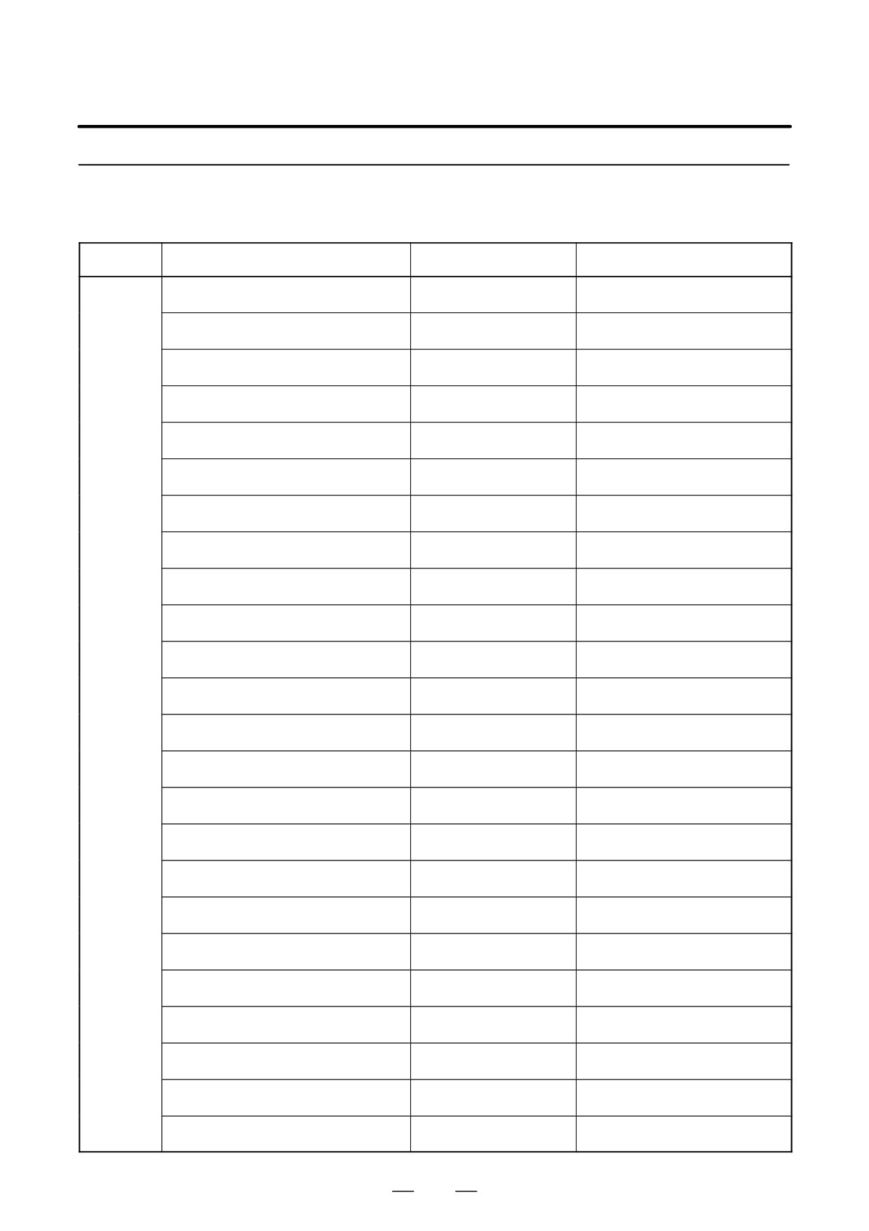
2.5.3
MDI Unit
Model
Name
Drawing number
Remarks
All models
T series/English/Small keyboard
A02B-0281-C120#TBR
Horizontal type, 200
140mm
T series/English/Standard keyboard
A02B-0281-C121#TBR
Vertical/horizontal type, 200
260mm
T series/English/Standard keyboard
A02B-0281-C125#TBR
Horizontal type, 220
230mm
T series/English/Standard keyboard
A02B-0281-C126#TBR
Vertical type, 220
290mm
M series/English/Small keyboard
A02B-0281-C120#MBR
Horizontal type, 200
140mm
M series/English/Standard keyboard
A02B-0281-C121#MBR
Vertical/horizontal type, 200
260mm
M series/English/Standard keyboard
A02B-0281-C125#MBR
Horizontal type, 220
230mm
M series/English/Standard keyboard
A02B-0281-C126#MBR
Vertical type, 220
290mm
61 full/English keyboard
A02B-0261-C162#MCR
Horizontal type, 220
230mm
61 full/English keyboard
A02B-0261-C161#MCR
Vertical type, 220
290mm
CAPi T/English keyboard
A02B-0281-C125#TFBR
Horizontal type, 220
230mm
CAPi T/English keyboard
A02B-0281-C126#TFBR
Vertical type, 220
290mm
T series/Symbol/Small keyboard
A02B-0281-C120#TBS
Vertical type, 200
140mm
T series/Symbol/Standard keyboard
A02B-0281-C121#TBS
Vertical/horizontal type, 200
260mm
T series/Symbol/Standard keyboard
A02B-0281-C125#TBS
Horizontal type, 220
230mm
T series/Symbol/Standard keyboard
A02B-0281-C126#TBS
Vertical type, 220
290mm
M series/Symbol/Small keyboard
A02B-0281-C120#MBS
Horizontal type, 200
140mm
M series/Symbol/Standard keyboard
A02B-0281-C121#MBS
Vertical/horizontal type, 200
260mm
M series/Symbol/Standard keyboard
A02B-0281-C125#MBS
Horizontal type, 220
230mm
M series/Symbol/Standard keyboard
A02B-0281-C126#MBS
Vertical type, 220
290mm
61 full/Symbol keyboard
A02B-0261-C162#MCS
Horizontal type, 220
230mm
61 full/Symbol keyboard
A02B-0261-C161#MCS
Vertical type, 220
290mm
CAPi T/Symbol keyboard
A02B-0281-C125#TFBS
Horizontal type, 220
230mm
CAPi T/Symbol keyboard
A02B-0281-C126#TFBS
Vertical type, 220
290mm
222
2. LCD-MOUNTED TYPE i SERIES
B-63525EN/02
HARDWARE
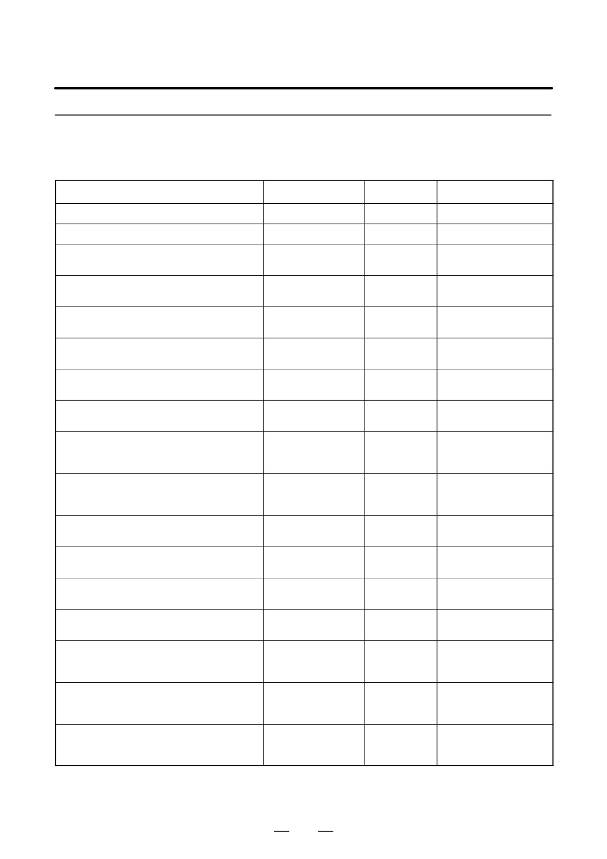
2.5.4
Printed Circuit Boards
Name
Drawing number
ID
Remarks
Motherboard for 16i
A20B-8100-0660
3x08
Motherboard for 18i
A20B-8100-0661
3x09
Motherboard for 21i
A20B-8100-0662
0x0A
(without Ethernet function, PMC-SA1)
Motherboard for 21i
A20B-8100-0663
1x0A
(without Ethernet function, PMC-SB7)
Motherboard for 21i
A20B-8100-0664
2x0A
(with Ethernet function, PMC-SA1)
Motherboard for 21i
A20B-8100-0665
3x0A
(with Ethernet function, PMC-SB7)
CPU card
A20B-3300-0310
CPU: 11
(16i/18i, DRAM 16MB)
DRAM: A9
CPU card
A20B-3300-0311
CPU: 11
(16i/18i, DRAM 32MB)
DRAM: AA
CPU card
A20B-3300-0312
CPU: 11
When the embedded
(21i, DRAM 16MB)
DRAM: A9
Ethernet function is used
with 21i.
CPU card
A20B-3300-0313
CPU: 11
When the embedded
(21i, DRAM 32MB)
DRAM: AA
Ethernet function is used
with 21i.
CPU card
A20B-3300-0290
CPU: 09
(21i, DRAM32MB)
DRAM: 8A
CPU card
A20B-3300-0291
CPU: 09
Used also for the loader
(21i, DRAM16MB)
DRAM: 89
control board
CPU card
A20B-3300-0102
0A
(standard type for RISC board)
CPU card
A17B-3300-0400
0A
(high-speed type for RISC board)
Display control card
A20B-3300-0280
0C
(10.4″ color LCD, graphic function, embedded
Ethernet function)
Display control card
A20B-3300-0281
08
(8.4″ color LCD, graphic function, embedded
Ethernet function)
Display control card
A20B-3300-0282
04
(9.5″ monochrome LCD, graphic function,
embedded Ethernet function)
223
2. LCD-MOUNTED TYPE i SERIES
HARDWARE
B-63525EN/02
Name
Drawing number
ID
Remarks
Display control card
A20B-3300-0283
00
(7.2″ monochrome LCD, graphic function,
embedded Ethernet function)
Display control card
A20B-3300-0300
07
(9.5″ monochrome LCD, embedded Ethernet
function)
Display control card
A20B-3300-0301
03
(7.2″ monochrome LCD, embedded Ethernet
function)
Display control card
A20B-3300-0302
07
(9.5″ monochrome LCD)
Display control card
A20B-3300-0303
03
(7.2″ monochrome LCD)
Axis control card
A20B-3300-0033
00
Applicable servo software:
(2 axes)
Series 9090
21i, Loader control
Axis control card
A20B-3300-0032
01
Applicable servo software:
(4 axes)
Series 9090
21i, Loader control
Axis control card
A20B-3300-0243
08
Applicable servo software:
(2 axes)
Series 90B0
Axis control card
A20B-3300-0242
08
Applicable servo software:
(4 axes)
Series 90B0
Axis control card
A20B-3300-0241
08
Applicable servo software:
(6 axes)
Series 90B0
Axis control card
A20B-3300-0240
08
Applicable servo software:
(8 axes)
Series 90B0
Axis control card
A20B-3300-0248
08
Applicable servo software:
(4 axes, high-speed HRV)
Series 90B0
Axis control card
A20B-3300-0245
08
Applicable servo software:
(6 axes, high-speed HRV)
Series 90B0
Axis control card
A20B-3300-0244
08
Applicable servo software:
(8 axes, high-speed HRV)
Series 90B0
Axis control card
A20B-3300-0246
08
Applicable servo software:
(Learning-control axis control)
Series 90B3/90B7
Axis control card
A20B-3300-0247
08
Applicable servo software:
(Learning-control axis control, high-speed HRV)
Series 90B3/90B7
Power supply unit
A20B-8100-0720
-
FROM/SRAM module
A20B-3900-0160
FROM: C1
(FROM 16MB, SRAM 1MB)
SRAM: 03
FROM/SRAM module
A20B-3900-0161
FROM: C1
(FROM 16MB, SRAM 2MB)
SRAM: 04
FROM/SRAM module
A20B-3900-0162
FROM: C1
(FROM 16MB, SRAM 3MB)
SRAM: 05
224
2. LCD-MOUNTED TYPE i SERIES
B-63525EN/02
HARDWARE
Name
Drawing number
ID
Remarks
FROM/SRAM module
A20B-3900-0163
FROM: C2
(FROM 32MB, SRAM 1MB)
SRAM: 03
FROM/SRAM module
A20B-3900-0164
FROM: C2
(FROM 32MB, SRAM 2MB)
SRAM: 04
FROM/SRAM module
A20B-3900-0165
FROM: C2
(FROM 32MB, SRAM 3MB)
SRAM: 05
FROM/SRAM module
A20B-3900-0180
FROM: C1
(FROM 16MB, SRAM 256kB)
SRAM: 01
FROM/SRAM module
A20B-3900-0181
FROM: C1
(FROM 16MB, SRAM 512kB)
SRAM: 02
FROM/SRAM module
A20B-3900-0182
FROM: C2
(FROM 32MB, SRAM 256kB)
SRAM: 01
FROM/SRAM module
A20B-3900-0183
FROM: C2
(FROM 32MB, SRAM 512kB)
SRAM: 02
Analog spindle module
A20B-3900-0170
-
DRAM module (4MB)
A20B-3900-0042
85
For option board
PMC-RE board
A20B-8100-0150
1xCD
C language board
A20B-8100-0261
0xCD
Serial communication board A
A20B-8100-0262
2xCD
Remote buffer/DNC2
Serial communication board B
A20B-8100-0263
3xCD
DNC1
Symbol CAPi T board
A20B-8100-0264
4xCD
Sub CPU board
A20B-8002-0190
1xCE
RISC board
A20B-8002-0040
xxCA
DATA SERVERboard
A20B-8100-0271
3xDB
ADD-ON board
A20B-2002-0960
-
Loader control board
A20B-8100-0830
1xD3
HSSB interface board
A20B-8001-0641
ExAA
I/O Link-II board
A20B-8100-0250
0x95
PROFIBUS board
A20B-8100-0430
0xBB
ADD-ON board
A20B-2100-0430
-
Ethernet board
A20B-8100-0271
3xDB
10BASE-T
DeviceNet interface board
A20B-8001-0880
1xF3
Backpanel (2 slots)
A20B-2003-0150
-
Backpanel (3 slots)
A20B-2003-0230
-
Backpanel (4 slots)
A20B-2003-0240
-
225
2. LCD-MOUNTED TYPE i SERIES
HARDWARE
B-63525EN/02
Name
Drawing number
ID
Remarks
Inverter
A20B-8100-0710
-
(for 9.5″ /7.2″ monochrome LCD)
Inverter
A20B-8001-0920
-
(for 10.4″ color LCD)
Inverter
A20B-8001-0922
-
(for 8.4″ color LCD)
PC-side HSSB interface board
A20B-8001-0582
-
(2CH, applicable to ISA bus)
PC-side HSSB interface board
A20B-8001-0583
-
(1CH, applicable to ISA bus)
PC-side HSSB interface board
A20B-8001-0960
-
(2CH, applicable to PCI bus)
PC-side HSSB interface board
A20B-8001-0961
-
(1CH, applicable to PCI bus)
Touch panel control board
A20B-8001-0620
-
226
2. LCD-MOUNTED TYPE i SERIES
B-63525EN/02
HARDWARE
2.5.5
I/O
Name
Drawing number
Remarks
Distributed I/O connector panel I/O module A1
A20B-2002-0470
DI/DO= 72/56
DI=general 16, matrix 56, with
MPG interface
Distributed I/O connector panel I/O module B1
A20B-2002-0520
DI/DO=48/32, with MPG interface
Distributed I/O connector panel I/O module B2
A20B-2002-0521
DI/DO=48/32
Distributed I/O connector panel I/O basic module
A03B-0815-C001
DI/DO=24/16
Distributed I/O connector panel I/O expansion module A
A03B-0815-C002
DI/DO=24/16, with MPG interface
Distributed I/O connector panel I/O expansion module B
A03B-0815-C003
DI/DO: 24/16
Distributed I/O connector panel I/O expansion module C
A03B-0815-C004
DO: 16 (2A output )
Distributed I/O connector panel I/O expansion module D
A03B-0815-C005
Analog input
Distributed I/O machine operator’s panel
A02B-0236-C141#TBS
DI=24, with MPG interface
(Small, Symbol keysheet)
Distributed I/O machine operator’s panel
A02B-0236-C141#TBR
DI=24, with MPG interface
(Small, English keysheet)
Distributed I/O machine operator’s panel
A02B-0236-C140#TBS
DI=24, with MPG interface
(Standard, Symbol keysheet)
Distributed I/O machine operator’s panel
A02B-0236-C140#TBR
DI=24, with MPG interface
(Standard, English keysheet)
Distributed I/O machine operator’s panel
A02B-0236-C150#TBS
DI=24, with MPG interface
(290mm-wide, Symbol keysheet)
Distributed I/O machine operator’s panel
A02B-0236-C150#TBR
DI=24, with MPG interface
(290mm-wide, English keysheet)
Main panel A machine operator’s panel
A02B-0236-C230
With MDI
(Symbol keyboard)
Main panel A1 machine operator’s panel
A02B-0236-C240
With MDI
(English keyboard)
Main panel B machine operator’s panel
A02B-0236-C231
Without MDI
(Symbol keyboard)
Main panel B1 machine operator’s panel
A02B-0236-C241
Without MDI
(English keyboard)
Sub panel A machine operator’s panel
A02B-0236-C232
Sub panel B machine operator’s panel
A02B-0236-C233
Sub panel B1 machine operator’s panel
A02B-0236-C235
Sub panel C machine operator’s panel
A02B-0236-C234
Operator’s panel connector unit (Sink type output A)
A16B-2200-0661
DI/DO: 64/32
Operator’s panel connector unit (Sink type output B)
A16B-2200-0660
DI/DO: 96/64
Operator’s panel connector unit (Source type output A)
A16B-2202-0731
DI/DO: 64/32
Operator’s panel connector unit (Source type output B)
A16B-2202-0730
DI/DO: 96/64
Machine operator’s panel interface unit
A16B-2201-0110
Loader I/O board
A02B-0236-C160
Loader I/O board
A02B-0236-C161
Matrix supported
FANUC I/O Link-AS-i converter
A03B-0817-C001
227
2. LCD-MOUNTED TYPE i SERIES
HARDWARE
B-63525EN/02
2.5.6
Other Units
Name
Drawing number
Remarks
Separate detector interface unit (basic 4 axes)
A02B-0236-C205
Separate detector interface unit (additional 4 axes)
A02B-0236-C204
Spindle distributed adapter
A13B-0180-B001
I/O Link distributed adapter
A20B-1007-0680
Optical I/O Link adapter
A13B-0154-B001
228
2. LCD-MOUNTED TYPE i SERIES
B-63525EN/02
HARDWARE
2.6
REPLACING THE
WARNING
MOTHERBOARD
Only those personnel who have received approved safety
and maintenance training may perform this replacement
work.
When opening the cabinet and replacing the board, be
careful not to touch the high-voltage circuits (marked and
fitted with an insulating cover). Touching the uncovered
high-voltage circuits presents an extremely dangerous
electric shock hazard.
CAUTION
Before starting replacement work, back up the contents
(such as parameters and programs) of the SRAM memory
of the CNC. Otherwise, the contents of the SRAM memory
may be lost during replacement work.
D Replacement procedure
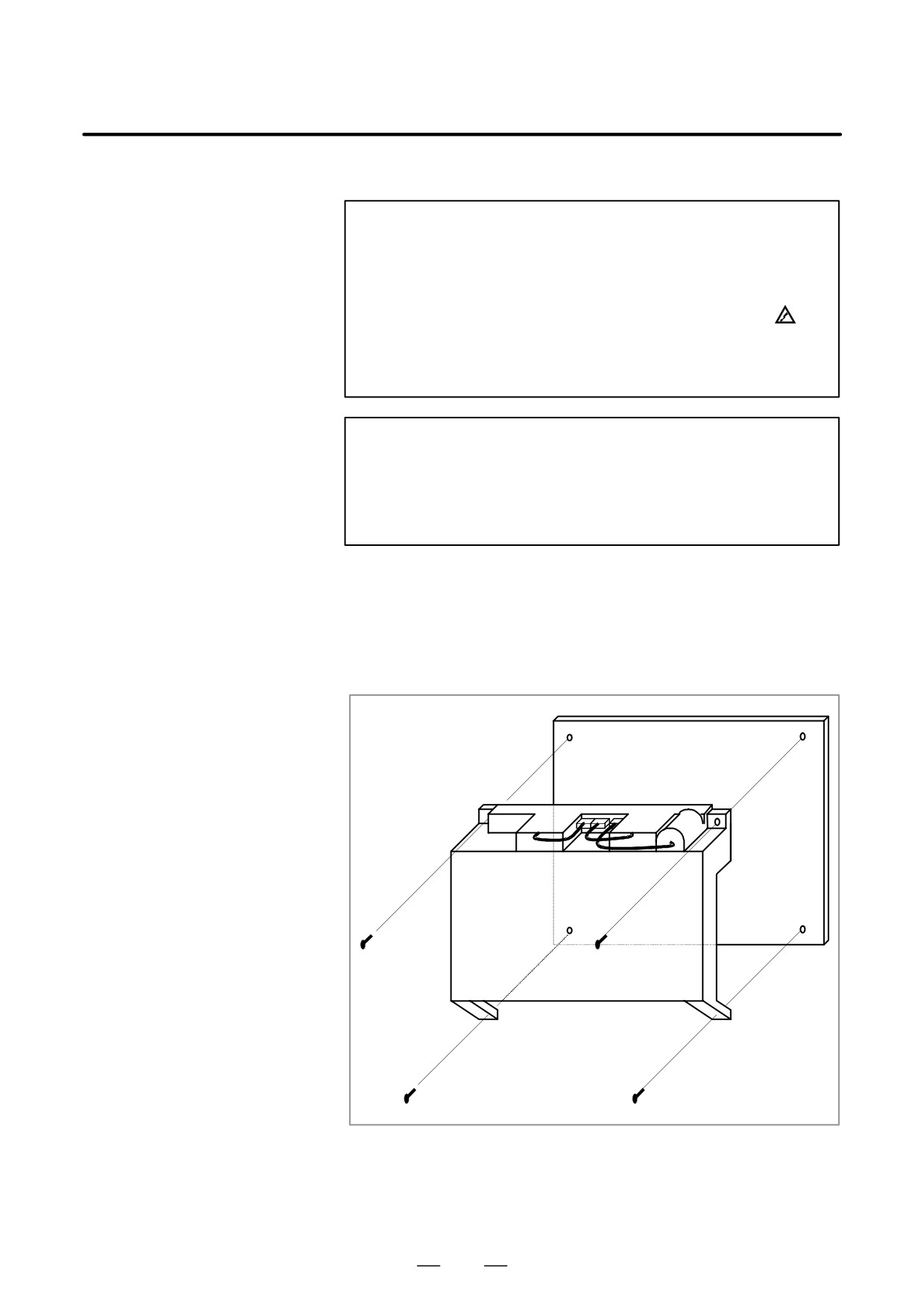
1) Unscrew the four screws fastening the case, and remove the case. The
fan and battery cable do not have to be removed.
If the unit has a touch panel, the touch panel control PCB is on the left
when viewed from the back of the basic unit. Before removing the
case, remove the cables connected to this touch panel control PCB
(connectors CN1 and CD37).
229
2. LCD-MOUNTED TYPE i SERIES
HARDWARE
B-63525EN/02
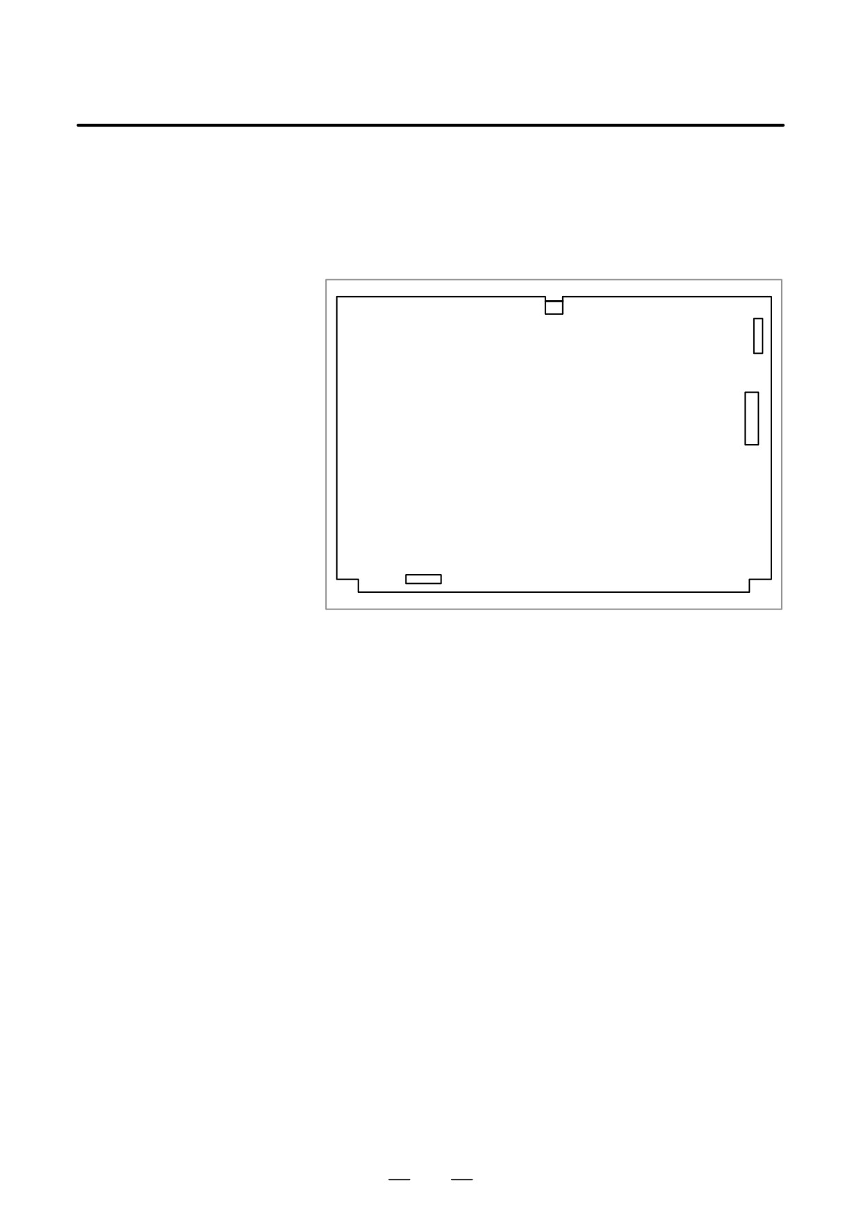
2) Remove the cables from connectors CNM1A (PCMCIA interface
connector), CN8 (video signal interface connector) and CN2 (soft key
connector) on the motherboard. Then, unscrew the screws fastening
the motherboard. The connector CN3 (inverter connector) directly
connects the motherboard to the inverter PCB. Slide the motherboard
downward when removing the motherboard.
CN3
CN8
CNM1A
Motherboard
CN2
3) When mounting the motherboard, reverse steps 1) and 2).
230
2. LCD-MOUNTED TYPE i SERIES
B-63525EN/02
HARDWARE
2.7
REPLACING FUSE
WARNING
ON CONTROL UNIT
Before replacing a blown fuse, locate and remove the cause
of the blown fuse.
For this reason, only those personnel who have received
approved safety and maintenance training may perform this
replacement work.
When opening the cabinet and replacing a fuse, be careful
not to touch the high-voltage circuits (marked
and fitted
with an insulating cover).
Touching the uncovered
high-voltage circuits presents an extremely dangerous
electric shock hazard.
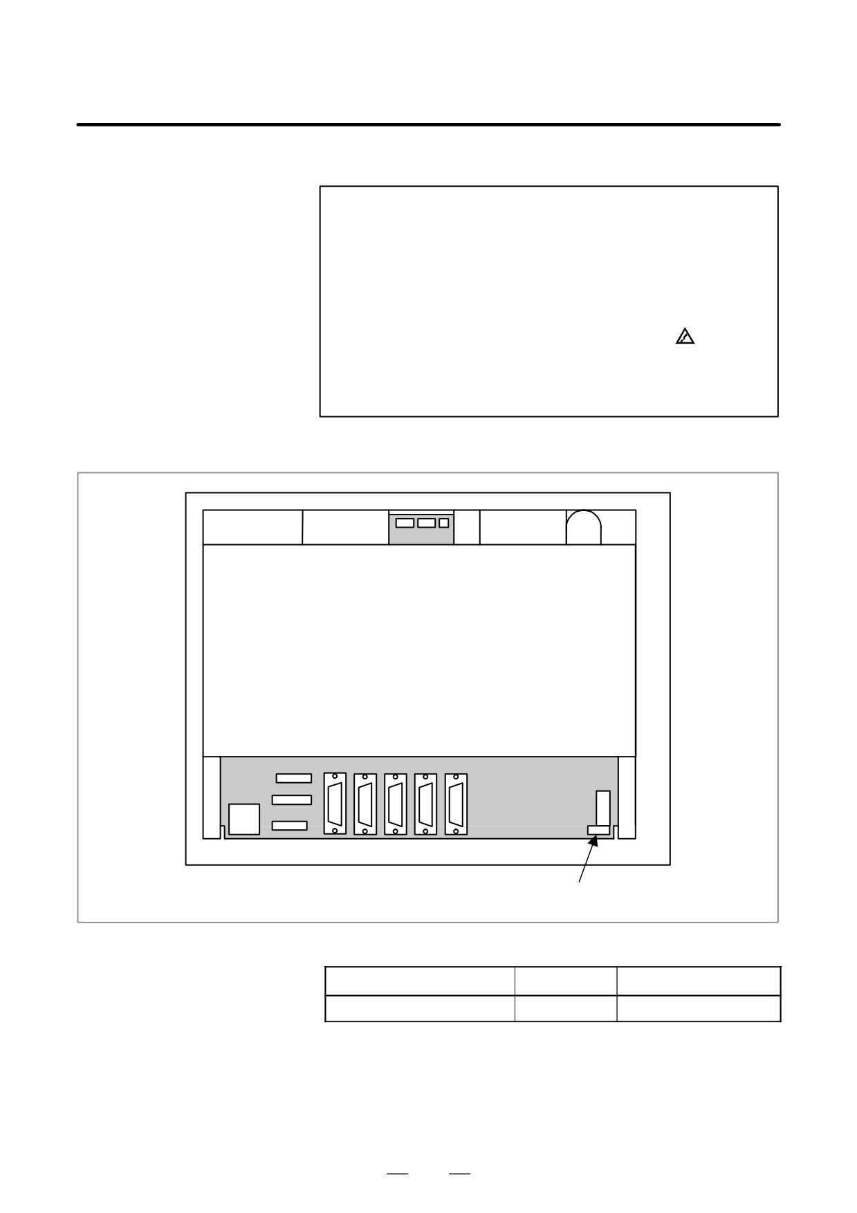
D Fuse mounting location
Rear of unit
CP1
FUSE
Fuse
D Ordering codes of fuses
Ordering code
Rating
Parts specification
A02B-0236-K100
5A
A60L-0001-0290#LM50C
231
2. LCD-MOUNTED TYPE i SERIES
HARDWARE
B-63525EN/02
Part programs, offset data, and system parameters are stored in CMOS
2.8
memory in the control unit. The power to the CMOS memory is backed
REPLACING
up by a lithium battery mounted on the front panel of the control unit. The
BATTERY
above data is not lost even when the main battery goes dead. The backup
battery is mounted on the control unit at shipping. This battery can
maintain the contents of memory for about a year.
When the voltage of the battery becomes low, alarm message “BAT”
blinks on the display and the battery alarm signal is output to the PMC.
When this alarm is displayed, replace the battery as soon as possible. In
general, the battery can be replaced within two or three weeks, however,
this depends on the system configuration.
If the voltage of the battery becomes any lower, memory can no longer
be backed up. Turning on the power to the control unit in this state causes
system alarm 910 (SRAM parity alarm) or 935 (SRAM ECC error) to
occur because the contents of memory are lost. Clear the entire memory
and reenter data after replacing the battery.
The following two kinds of batteries can be used.
D Lithium battery built into the CNC control unit.
D Two alkaline dry cells (size D) in the external battery case.
NOTE
A lithium battery is installed as standard at the factory.
D Replacement procedure
When a lithium battery is used
Prepare a new lithium battery
(ordering code: A02B-0200-K102
(FANUC specification: A98L-0031-0012)).
1) Turn on the power to the CNC. After about 30 seconds, turn off the
power.
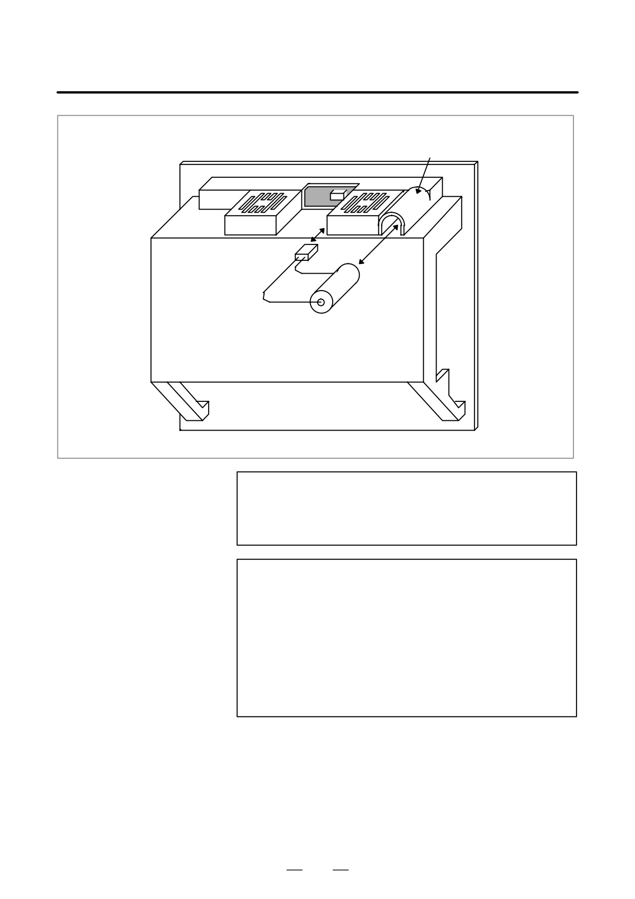
2) Remove the old battery from the top of the CNC control unit.
First, unplug the battery connector, then take the battery out of its
case.
The battery case of a control unit without option slots is located at the
top end of the unit as shown in the figure of the previous page. The
battery case of a control unit with 2 slots or 4 slots is located in the
central area of the top of the unit (between fans).
3) Insert a new battery and reconnect the connector.
232
2. LCD-MOUNTED TYPE i SERIES
B-63525EN/02
HARDWARE
Battery case
Connector
Lithium battery
A02B-0200-K102
WARNING
Using other than the recommended battery may result in the
battery exploding. Replace the battery only with the
specified battery (A02B-0200-K102).
CAUTION
Steps 1) to 3) should be completed within 30 minutes. Do
not leave the control unit without a battery for any longer
than the specified period. Otherwise, the contents of
memory may be lost.
If steps 1) to 3) may not be completed within 30 minutes,
save all contents of the SRAM memory to the memory card
beforehand. Thus, if the contents of the SRAM memory are
lost, the contents can be restored easily.
For the method of operation, refer to 4.9 or C.2.2.
When discarding a battery, observe the applicable ordinances or other
rules of your local government. Also, cover the terminals of the battery
with vinyl tape or the like to prevent a short-circuit.
233
2. LCD-MOUNTED TYPE i SERIES
HARDWARE
B-63525EN/02
When using commercial
alkaline dry cells (size D)
D Method of connection
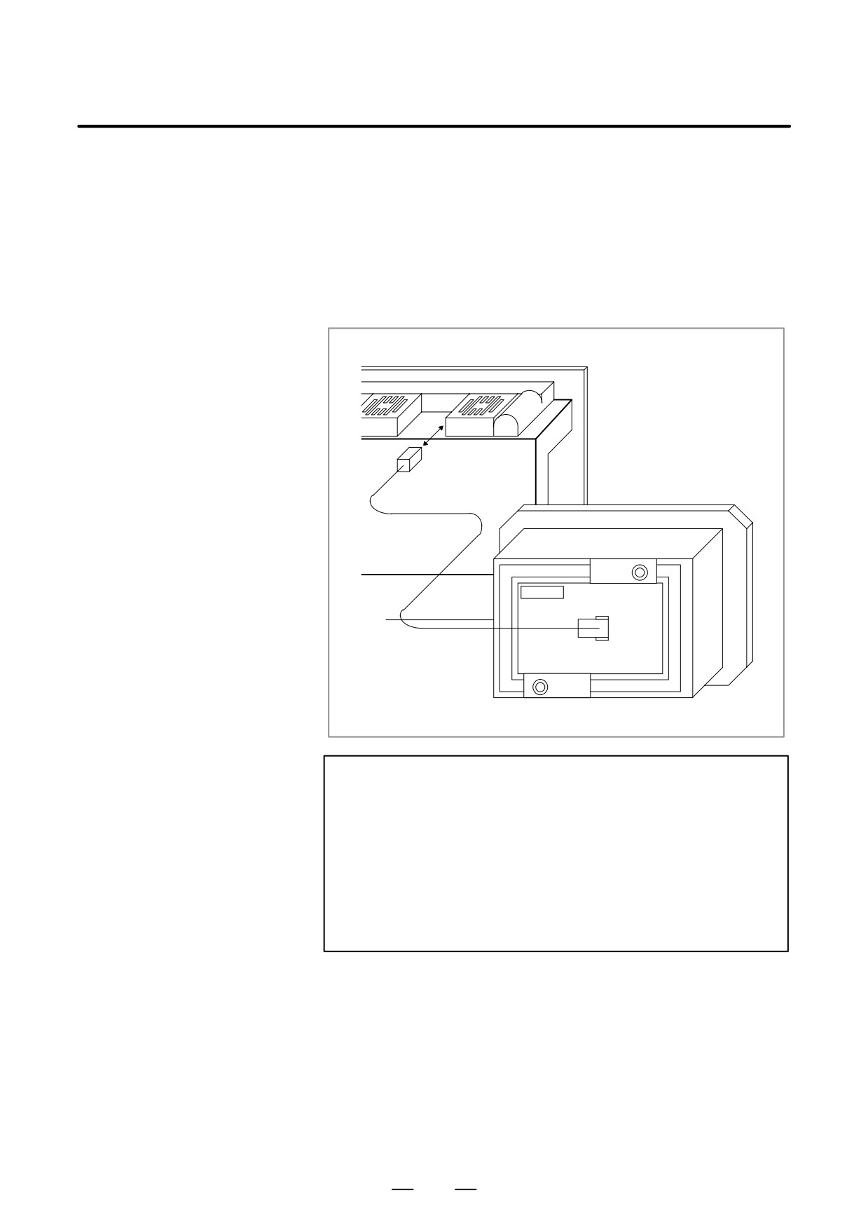
Power from the external batteries is supplied through the connector to
which the lithium battery is connected.
The lithium battery, provided as standard, can be replaced with external
batteries in the battery case (A02B-0236-C281) according to the battery
replacement procedure described above.
CAUTION
1
Install the battery case (A02B-0236-C281) in a location
where the batteries can be replaced even when the power
to the control unit is on.
2
The battery cable connector is attached to the control unit
by means of a simple lock system. To prevent the connector
from being disconnected due to the weight of the cable or
tension within the cable, fix the cable section within 50 cm
of the connector.
234
2. LCD-MOUNTED TYPE i SERIES
B-63525EN/02
HARDWARE
Replacing
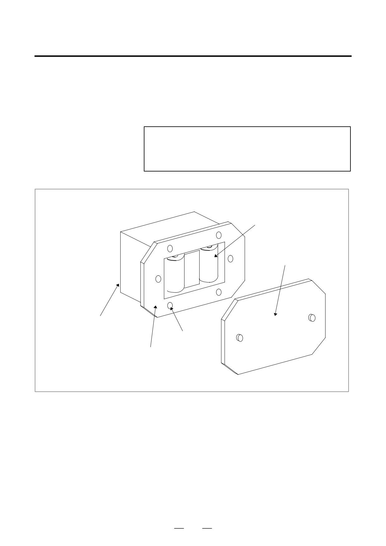
1) Prepare two alkaline dry cells (size D) commercially available.
commercial alkaline dry
2) Turn on the power to the control unit.
cells (size D)
3) Remove the battery case cover.
4) Replace the cells, paying careful attention to their orientation.
5) Reinstall the cover onto the battery case.
CAUTION
When replacing the alkaline dry cells while the power is off,
use the same procedure as that for lithium battery
replacement described above.
Alkaline dry cell x 2
Cover
Connection terminal on the rear
Mounting hole x 4
Battery case
235
2. LCD-MOUNTED TYPE i SERIES
HARDWARE
B-63525EN/02
2.9
REPLACING FAN
WARNING
MOTORS
When opening the cabinet and replacing a fan motor, be
careful not to touch the high-voltage circuits (marked and
fitted with an insulating cover).
Touching the uncovered high-voltage circuits presents an
extremely dangerous electric shock hazard.
D Fan ordering information
Ordering information
Required quantity
Unit with no option slot
A02B-0236-K120
2
Unit with 2 option slots
A02B-0281-K121
2
Unit with 3 option slots
A02B-0281-K121
2
A02B-0236-K122
2
Unit with 4 option slots
A02B-0281-K121
4
236
2. LCD-MOUNTED TYPE i SERIES
B-63525EN/02
HARDWARE
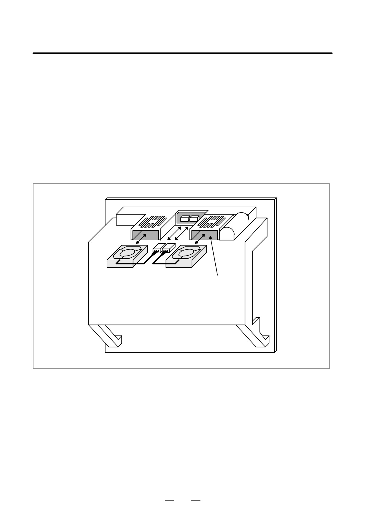
Replacement procedure
D For units with no
1. Before replacing a fan motor, turn off the power to the CNC.
expansion slots and
2. Unplug the connector of a fan motor to be replaced ( (1) of Fig. a).
units with 2 expansion
The connector is latched. So, when unplugging the connector, hold
slots
down the latch placed at the lower part of the connector with a
flat-blade screwdriver.
3. Detach the latch securing the fan motor, then demount the fan motor
( (2) of Fig. a).
4. Insert a new fan motor into the fan case ( (3) of Fig. a), then reconnect
the connector.
Fig. a
(1) Connector
(2) Fan
(3) Fan case
Note) Install a fan so that it flows air in the upward
direction.
(Face the label upward.)
237
2. LCD-MOUNTED TYPE i SERIES
HARDWARE
B-63525EN/02
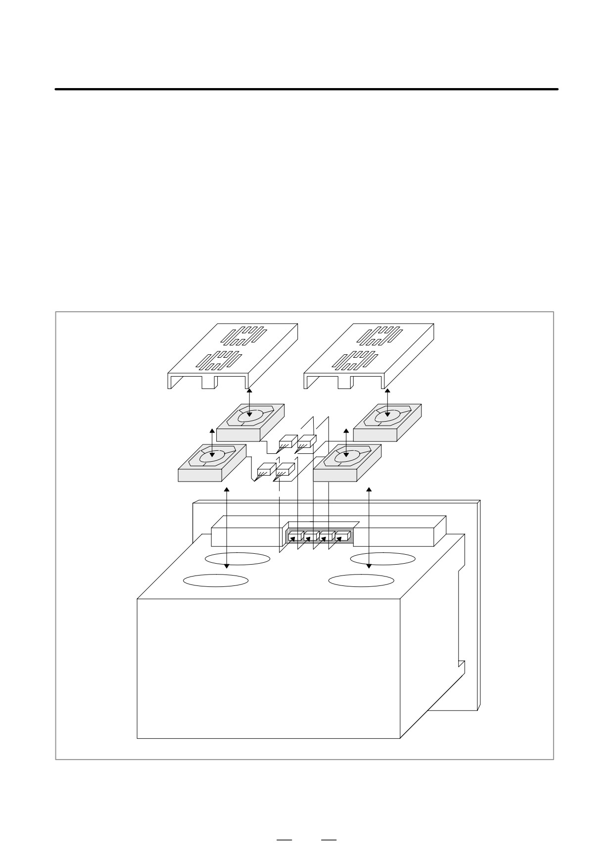
D For units with 3 or 4
1. Before replacing a fan motor, turn off the power to the CNC.
expansion slots
2. Unplug the connector of a fan motor to be replaced ( (1) of Fig. b).
The connector is latched. So, when unplugging the connector, hold
down the latch placed at the lower part of the connector with a
flat-blade screwdriver.
3. Detach the latch securing the fan cover ( (3) of Fig. b), then demount
the fan cover from the unit.
4. The fan is secured to the fan cover. Detach the latch, then demount
the fan motor ( (2) of Fig. b).
5. Install a new fan motor onto the fan cover. Then, reinstall the fan
cover onto the unit, and reconnect the connector.
Fig. b
(3) Fan cover
(2) Fan
(1) Connector
Note) Install a fan so that it flows air in the up-
ward direction.
(Face the label upward.)
238
2. LCD-MOUNTED TYPE i SERIES
B-63525EN/02
HARDWARE
2.10
REPLACING LCD
WARNING
BACKLIGHT
Only those personnel who have received approved safety
and maintenance training may perform this replacement
work.
When opening the cabinet and replacing a unit, be careful
not to touch the high-voltage circuits (marked
and fitted
with an insulating cover).
Touching the uncovered high-voltage circuits presents an
extremely dangerous electric shock hazard.
CAUTION
Before starting replacement work, back up the contents
(such as parameters and programs) of the SRAM memory
of the CNC. Otherwise, the contents of the SRAM memory
may be lost during replacement work.
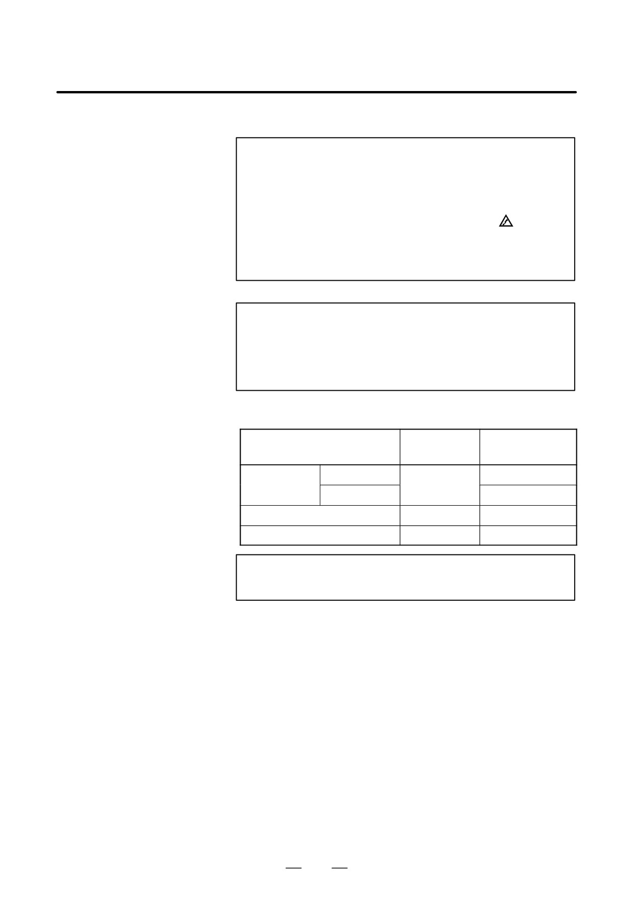
D Backlight ordering
information
Ordering
Individual ordering
Backlight
information
information
Made by Hitachi
A61L-0001-0142#BL
For 7.2″
LCD
A02B-0236-K112
Made by Sharp
A61L-0001-0142#BLS
For 8.4″ LCD
A02B-0236-K119
A61L-0001-0176#BL
For 9.5″ LCD
A02B-0281-K114
A61L-0001-0154#BLC
NOTE
The back-light of the 10.4I color LCD cannot be replaced.
239
2. LCD-MOUNTED TYPE i SERIES
HARDWARE
B-63525EN/02
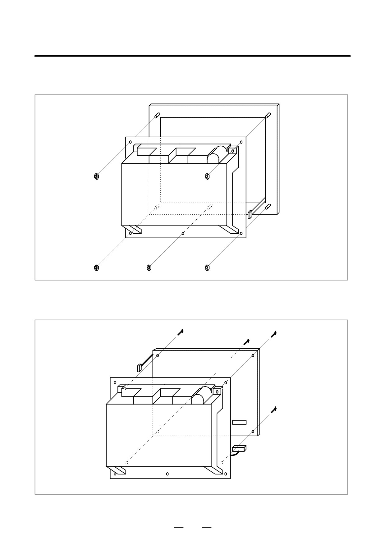
D Replacement procedure
1) Detach the flat cable for soft keys, then detach the escutcheon from
the CNC.
Escutcheon
Flat cable for soft keys
2) As shown below, unplug the connectors CP1 and CN8 to detach the
LCD unit from the CNC unit.
LCD unit
CP1
CN8
CN8
240
2. LCD-MOUNTED TYPE i SERIES
B-63525EN/02
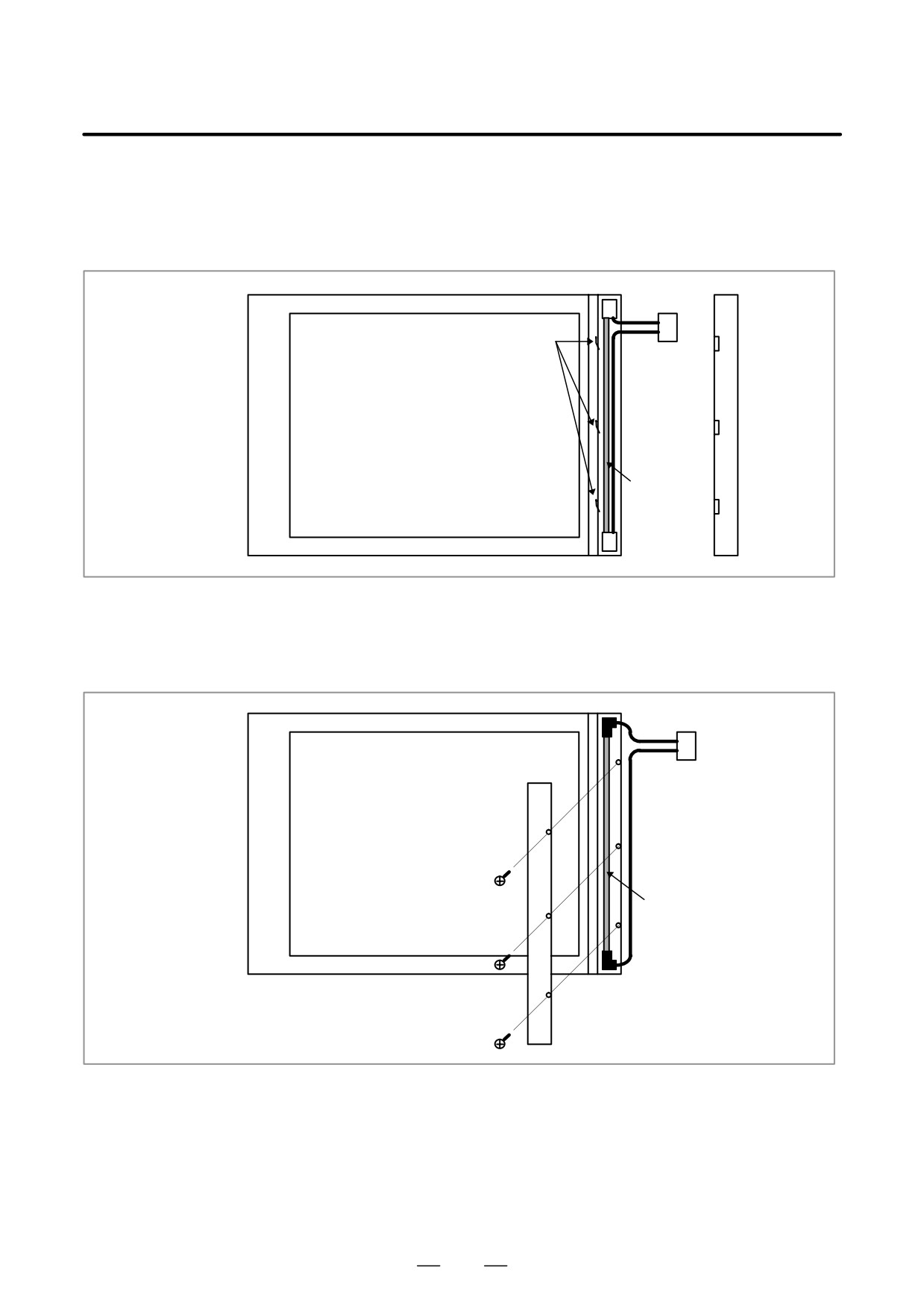
HARDWARE
3)-1 For the 7.2″ LCD units (monochrome) manufactured by Hitachi
Remove the three brackets from the left part on the front of the LCD
unit, and remove the cover. Then, the backlight is exposed. Replace
the backlight with a new one.
Connector
Bracket
Display surface of LCD unit
Backlight
3)-2 For the 7.2″ LCD unit (monochrome) manufactured by Sharp
Remove the three screws from the left part on the front of the LCD
unit, and remove the cover. Then, the backlight is exposed. Replace
the backlight with a new one.
Connector
Display surface of LCD unit
Backlight
241