FANUC Series 16i/160i/160is-MODEL B, Series 18i/180i/180is-MODEL B, Series 21i/210i/210is-MODEL B. MAINTENANCE MANAUL - page 7
1. DISPLAY AND OPERATION
B-63525EN/02
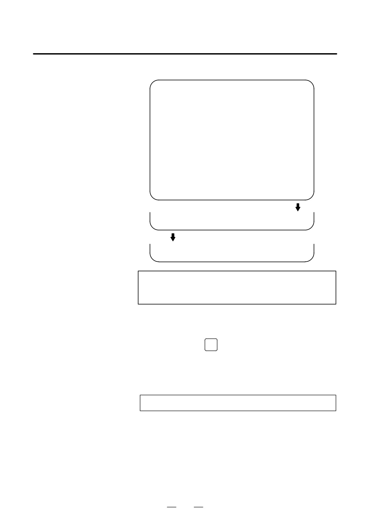
[NC system] menu screen
PERIODICAL MAINTENANCE
O0001 N12345
(NC)
ITEM NAME
01
BATTERY FOR CONTROLLER
02
BATTERY FOR PULSECODER
03
FAN MOTOR
04
LCD BACK LIGHT
05
06
07
08
09
10
>_
EDIT *** ***** *** ****
19:27:05
[
][ STATUS ][ MACHIN ][ NC
][ (OPRT) ]
[ SELECT ][
][
][
][
]
[
][
][
][ CAN
][ EXEC
]
NOTE
On the NC system screen, no item name can be registered,
erased, input, or output.
(2) MDI keypad-based setting
An item name can be registered on the status screen by first entering
it in the following format using keys, then pressing soft key
[INPUT] (or the
INPUT
key).
Pressing soft key [+INPUT] adds the item name to the list of
previously registered item names.
Format
Alphanumeric characters*two-byte characters*alphanumeric characters
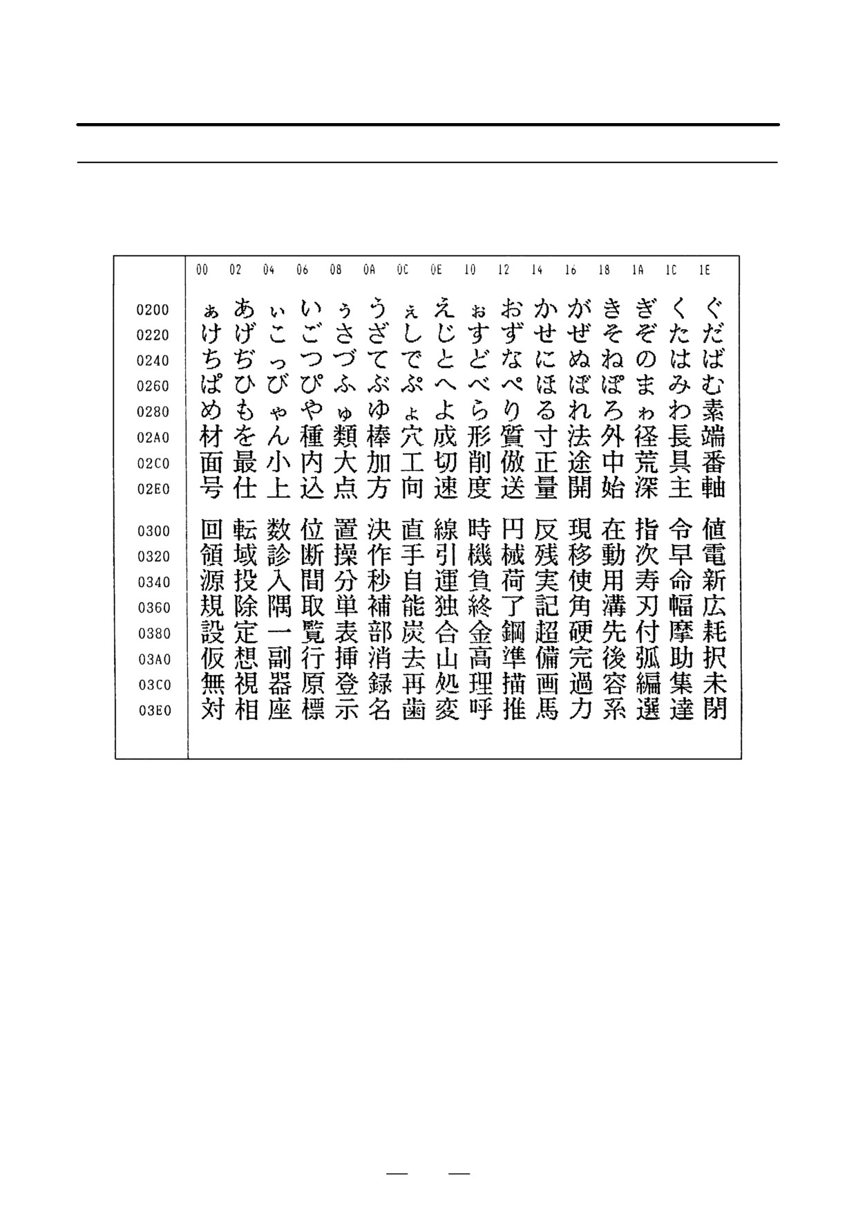
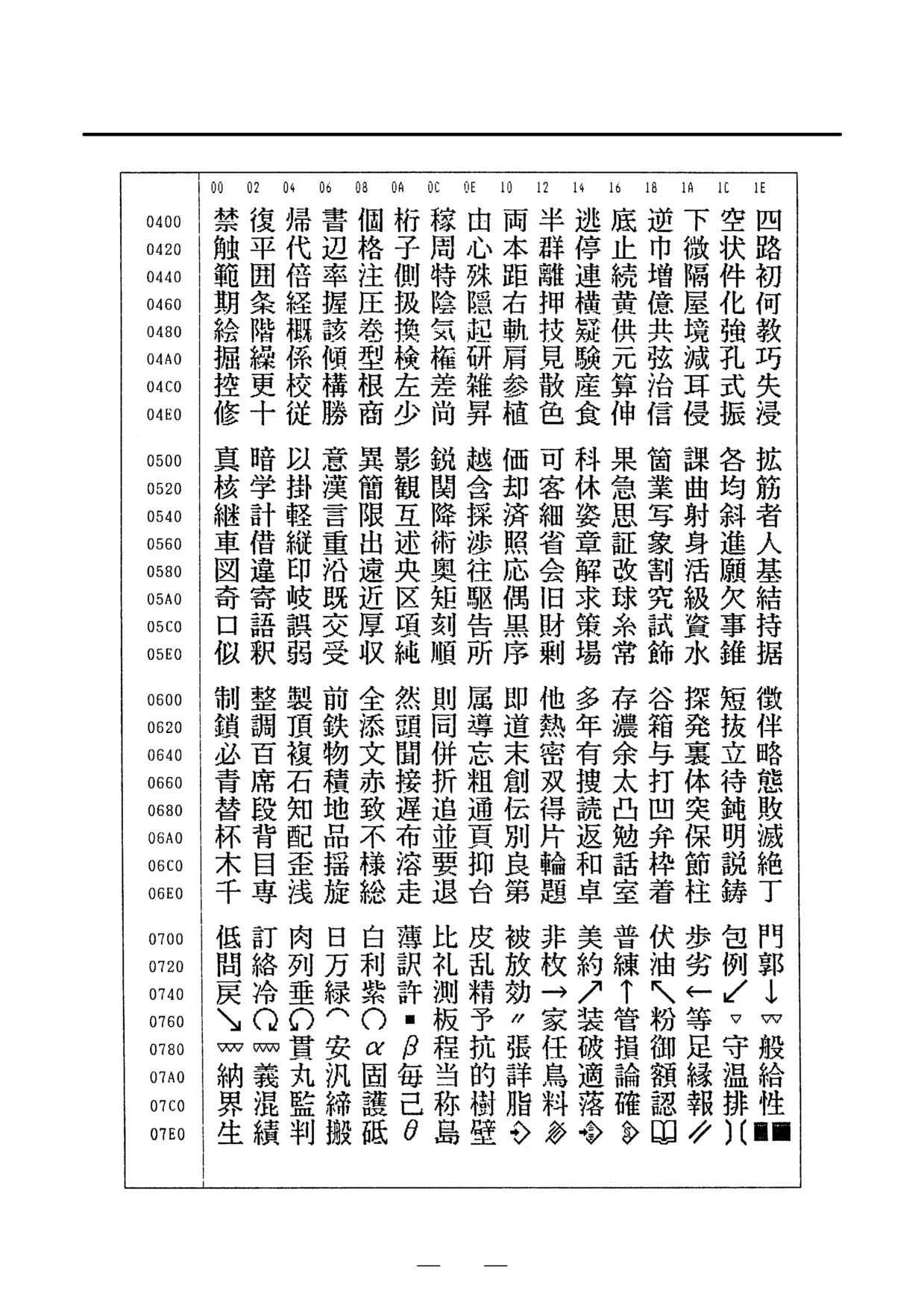
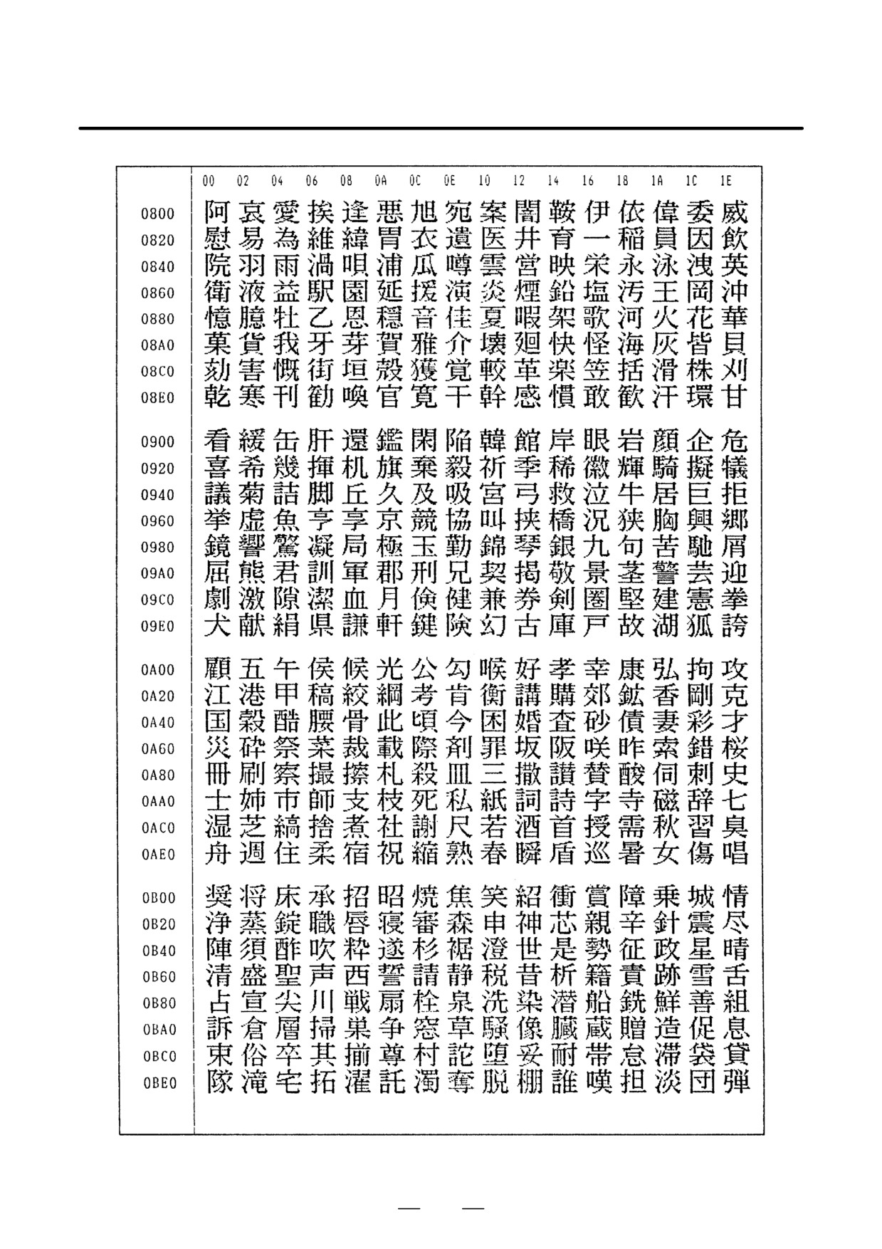
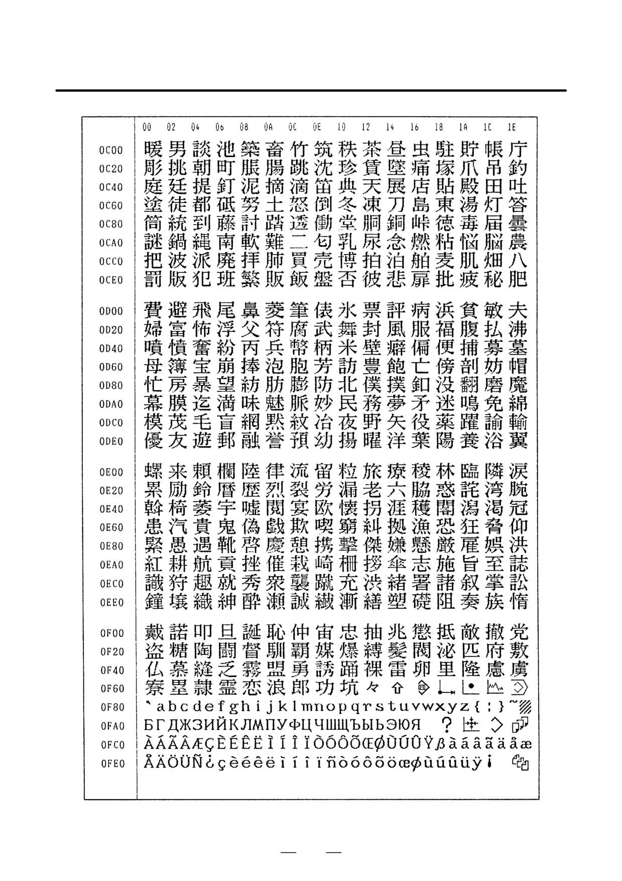
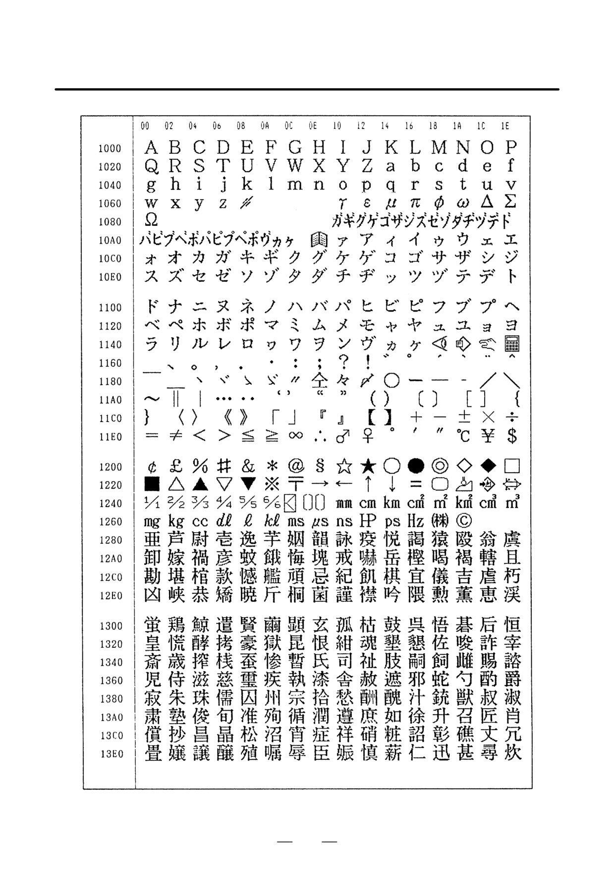
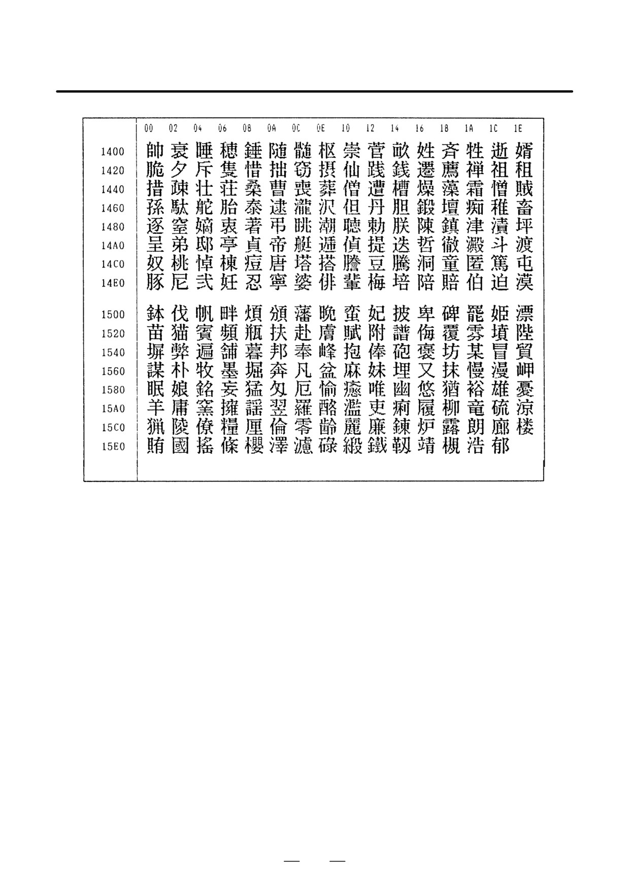
The two-byte characters shall comply with the FANUC code. (See
Section 1.19.6.)
When entering a two-byte character using keys, sandwich it with
an “*” pair.
The item name can consist of up to 24 alphanumeric characters (if
no two-byte character is included) or 12 two-byte characters (if no
alphanumeric character is included).
Example) To register “LCD backlight,” enter:
>LCD*110E10F410CC114010B610FE_
152
B-63525EN/02
1. DISPLAY AND OPERATION
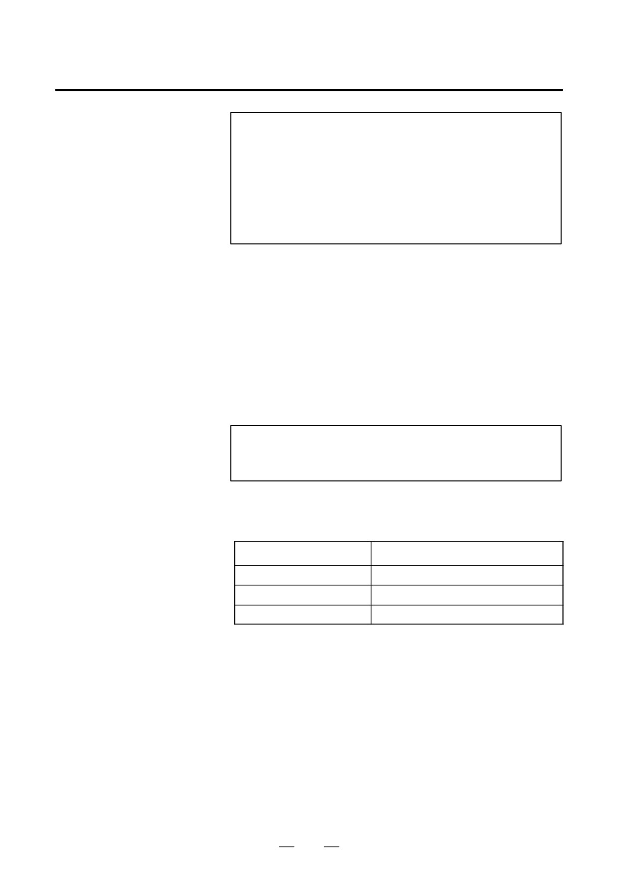
NOTE
1
“*” cannot be used in item names, because it is used as
control code.
“[”, “]”, “(“, or “)” also cannot be used in item
names.
2
When both alphanumeric and two-byte characters are
used in an item name to be registered, the warning
message “DATA IS OUT OF RANGE” may appear even if
the maximum allowable number of characters has not been
exceeded.
To erase the registered data for an item, place the cursor on the
target item name, press soft key [CLEAR], then [EXEC].
When an item name is deleted, the related service life, remaining
service time, and count type are also deleted.
(2) Remaining service time
The remaining service time of an item (the time allowed before the
item is replaced) is obtained by count-down and displayed under
“Remaining service time.” When the remaining service time
decreases to a specified percentage (specified in parameter No. 8911)
of the service life or lower, it is displayed in red.
Count-down continues even after the service life has expired.
NOTE
Setting is impossible on the status screen.
It should be done on the setting screen.
(3) Count status
The count status is displayed at the left of the corresponding item
number, as listed below:
Display
Count status
Blank
Count suspended
@
Count under way
The service life has expired.
153
1. DISPLAY AND OPERATION
B-63525EN/02
1.19.4
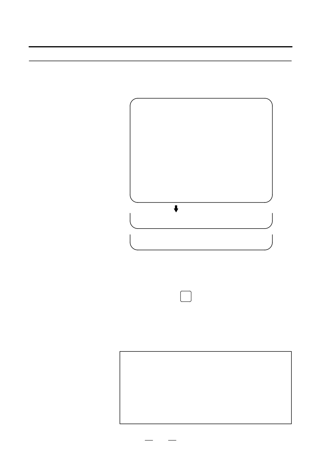
The setting screen lets you specify the service life, the remaining service
time, and count type for a registered item name.
Setting Screen Display
It also displays the same count status information as displayed on the
and Setting
status screen.
PERIODICAL MAINTENANCE
O0001 N12345
(SETTING)
LIFE
REMAIN
COUNT TYPE
*01
10000H
0H
ALL TIME
@02
20000H
5000H
LIV TIME
03
32767H
10000H
--------
@04
1500H
720H
RUN TIME
05
06
07
08
09
10
>_
EDIT *** ***** *** ****
19:27:05
[ CHANGE ][ TYPE ][ CLEAR ][ +INPUT ][ INPUT ]
[ EFFECT ][ ALL
][ LIV
][ RUN
][ CUT
]
[
][ READ
][ PUNCH ][
][
]
(1) Service life
The service life of a consumable item is to be specified under “Service
life.”
First place the cursor on the service life of a target registration number,
enter a desired service life value using numeric keys, then press soft
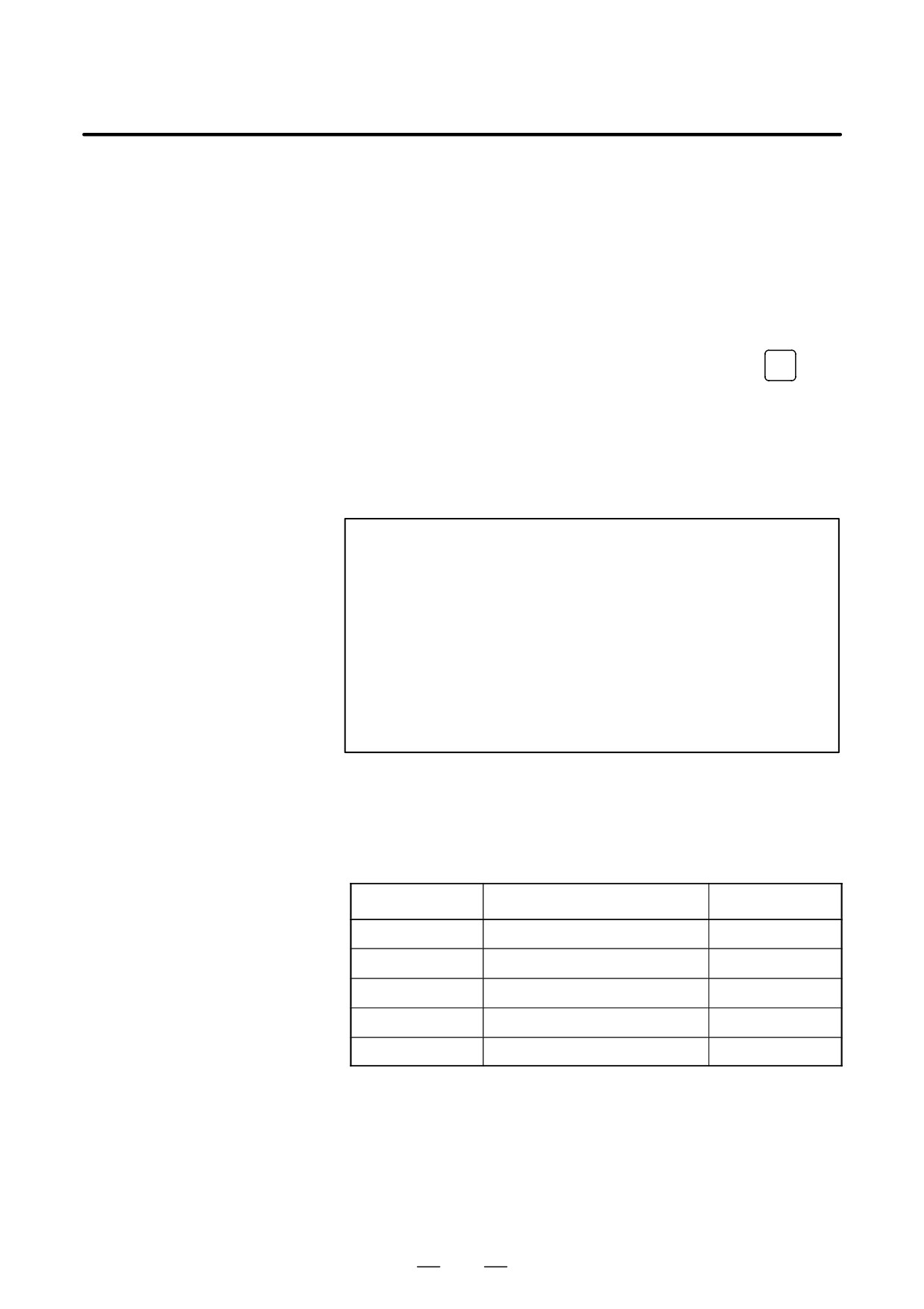
key [INPUT] (or the
INPUT
key). The specified service life is set up,
and the same value is set up also under “Remaining service time.”
In addition, the count type for the item changes to:
“------”
Pressing soft key [+INPUT] adds the newly specified service life value
to the previously specified life value. The added service life value is
reflected to the remaining service time.
The valid data range for the service life is:
0 to 65535 (hours)
NOTE
1
An attempt to set up the service life for a non-registered
item results in the warning message “EDIT REJECTED”.
2
An attempt to enter a value that is out of the valid data range
results in the warning message “DATA IS OUT OF RANGE”.
3
An attempt to enter a value that would make the service life
or remaining service time 0 or lower, it is clamped at 0.
4
Pressing soft keys [CLEAR] and [TYPE] results in the
warning message “EDIT REJECTED”.
154
B-63525EN/02
1. DISPLAY AND OPERATION
(2) Remaining service time
The remaining service time of an item (the time allowed before the
item is replaced) is determined by count-down and displayed under
“Remaining service time.” When the remaining service time
decreases to a specified percentage (specified in parameter No. 8911)
of the service life or lower, it is displayed in red.
Count-down continues even after the service life has expired.
First place the cursor on the remaining service time of a target
registration number, enter a desired remaining service time value
using numeric keys, then press soft key [INPUT] (or the
INPUT
key).
Pressing soft key [+INPUT] adds the newly specified remaining
service time to the previously specified remaining service time.
The valid data range for the remaining service time is:
0 to (service
life)
After soft key [CLEAR] is pressed, pressing soft key [EXEC] sets the
remaining service time with the same value as for the service life.
NOTE
1
An attempt to set up the remaining service time for a non-
registered item or an item for which the service life has not
been set up results in the warning message
“EDIT
REJECTED”.
2
An attempt to enter a value that is out of the valid data range
results in the warning message “DATA IS OUT OF RANGE”.
3
An attempt to enter a value that would make the remaining
service time 0 or lower, it is clamped at 0.
4. Pressing soft key [TYPE] results in the warning message
“EDIT REJECTED”.
(3) Count type
The type of a selected count method is specified under “Count type.”
After the cursor is placed on the count type of a target registration
number, pressing soft key [TYPE] displays the next count type as a
soft key. Select it and press soft key [EXEC].
Soft key
Meaning
Display
[NO CNT]
Not counting (suspended).
—
[ ALL ]
Always count.
All times
[PWR ON]
Count while the power is supplied.
Power-on time
[ RUN ]
Count while operation is under way.
Operating
[ CUT ]
Count while cutting is under way.
Cutting
155
1. DISPLAY AND OPERATION
B-63525EN/02
NOTE
1
An attempt to set up the count type for a non-registered
item or an item for which the service life has not been set up
results in the warning message “EDIT REJECTED”.
2
Soft keys [INPUT] and [+INPUT] are ignored.
3
In leap years, an error of 24 hours occurs in the all-time
count.
4
Pressing soft key [CLEAR] results in the warning message
“EDIT REJECTED”.
Pressing soft key [PUNCH] enables registered data to be output to an
1.19.5
external unit.
Registered Data
Pressing soft key [READ] enables data to be input from an external unit.
Input/Output
These operations can be done on the status, setting, and machine system
menu screens.
EDIT *** ***** *** ****
19:27:05
[
][ READ
][ PUNCH ][
][
]
[
][
][
][ CAN
][ EXEC
]
D Data output
After the EDIT mode is selected, pressing soft key [PUNCH] outputs the
registered data in the following format.
Format
- Format for output from the status and setting screens
G10 L60 P01 Aa Rr [n] Qq ;
G10 L60 P02 Aa Rr [n] Qq ;
G10 L60 P03 Aa Rr [n] Qq ;
:
Format
- Format for output from the machine system menu
G10 L61 P01 [n] ;
G10 L61 P02 [n] ;
G10 L61 P03 [n] ;
:
156
B-63525EN/02
1. DISPLAY AND OPERATION
a : Service life
r
: Remaining service time
n : Item name
[Alphanumeric characters*two-byte characters * alphanumeric
characters
q : count type
0 = not to count
1 = count at all times
2 = count during power-on time
3 = count during operation
4 = count during cutting
D Data input
After the EDIT mode is selected, pressing soft key [READ] causes data
to be registered with item names according to the format in which the data
is input (G10).
Data registration can be done even by executing the format (G10) once
input to the program memory.
This requires a programmable data input option.
NOTE
If the input format (G10) differs from the output format,
registration may fail.
Parameter
8911
Percentage to the service life of each item displayed on the periodic
maintenance screen
[Data type] Byte
[Unit of data] 1%
[Valid data range] 0 to 100
On the periodic maintenance screens, any remaining service time value
smaller than the specified percentage to the service life is displayed in red
for warning purposes.
157
1. DISPLAY AND OPERATION
B-63525EN/02
1.19.6
FANUC Two-Byte
Character Code Table
158
B-63525EN/02
1. DISPLAY AND OPERATION
159
1. DISPLAY AND OPERATION
B-63525EN/02
160
B-63525EN/02
1. DISPLAY AND OPERATION
161
1. DISPLAY AND OPERATION
B-63525EN/02
162
B-63525EN/02
1. DISPLAY AND OPERATION
163
2. LCD-MOUNTED TYPE i SERIES
HARDWARE
B-63525EN/02
LCD-MOUNTED TYPE i SERIES HARDWARE
2
This chapter describes the printed-circuit board in the i series CNC
control unit of LCD-mounted type and the functions of the card PCBs
mounted on the printed-circuit board. It also explains how to replace
consumables.
2.1
STRUCTURE
165
2.2
OVERVIEW OF HARDWARE
166
2.3
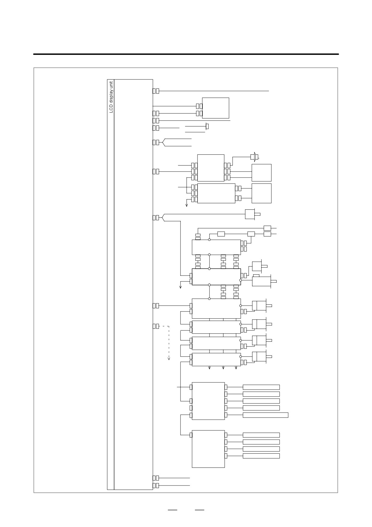
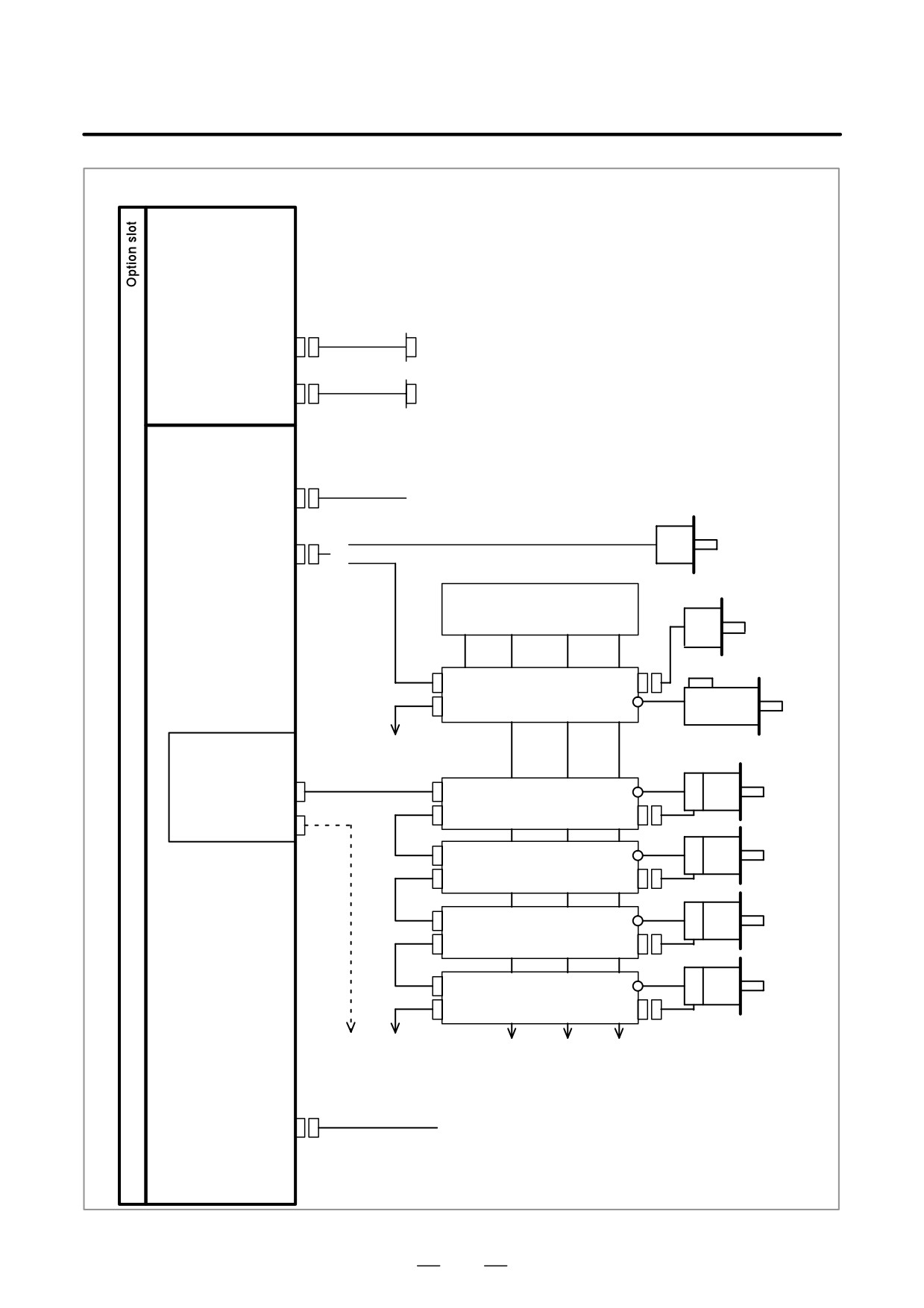
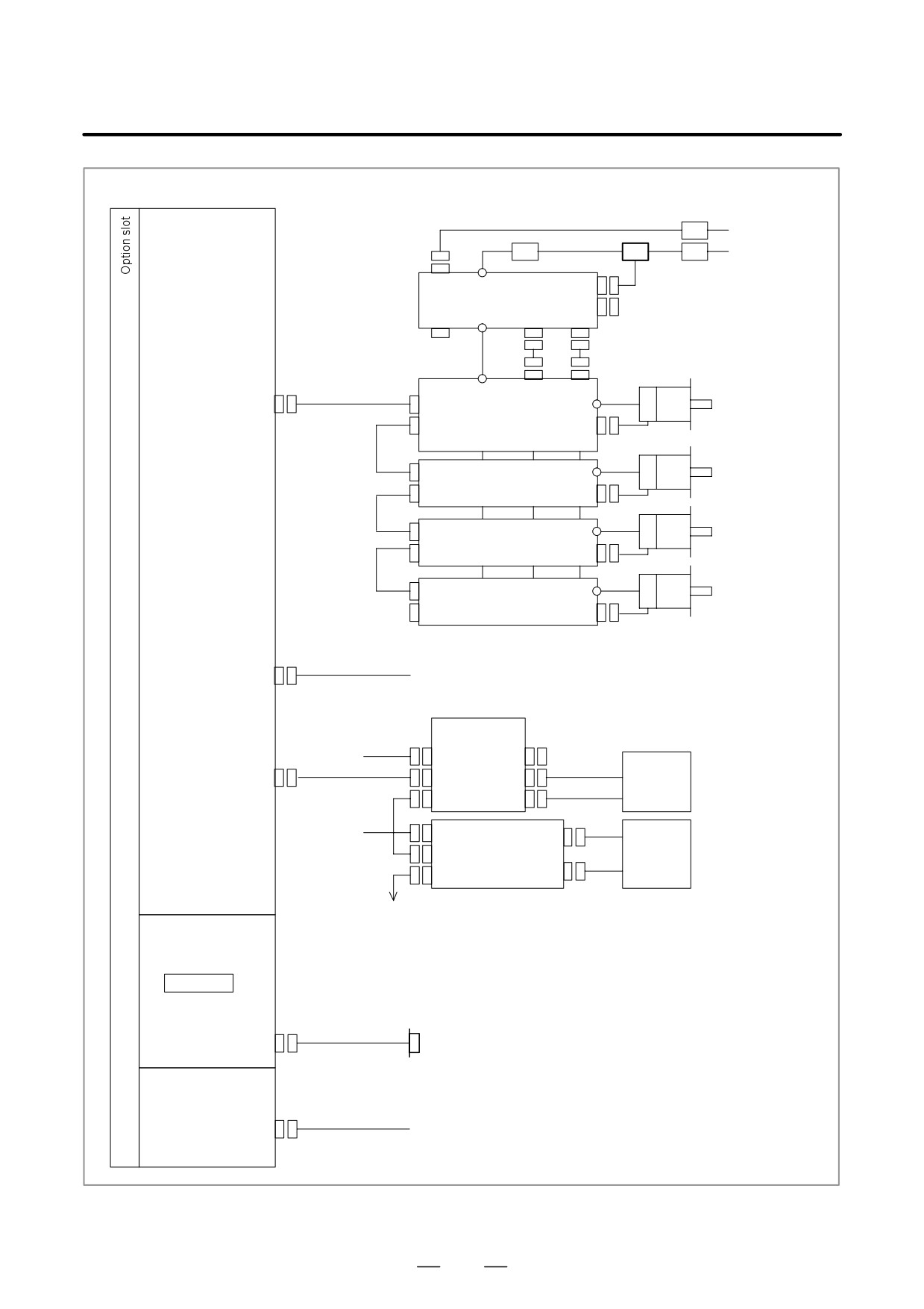
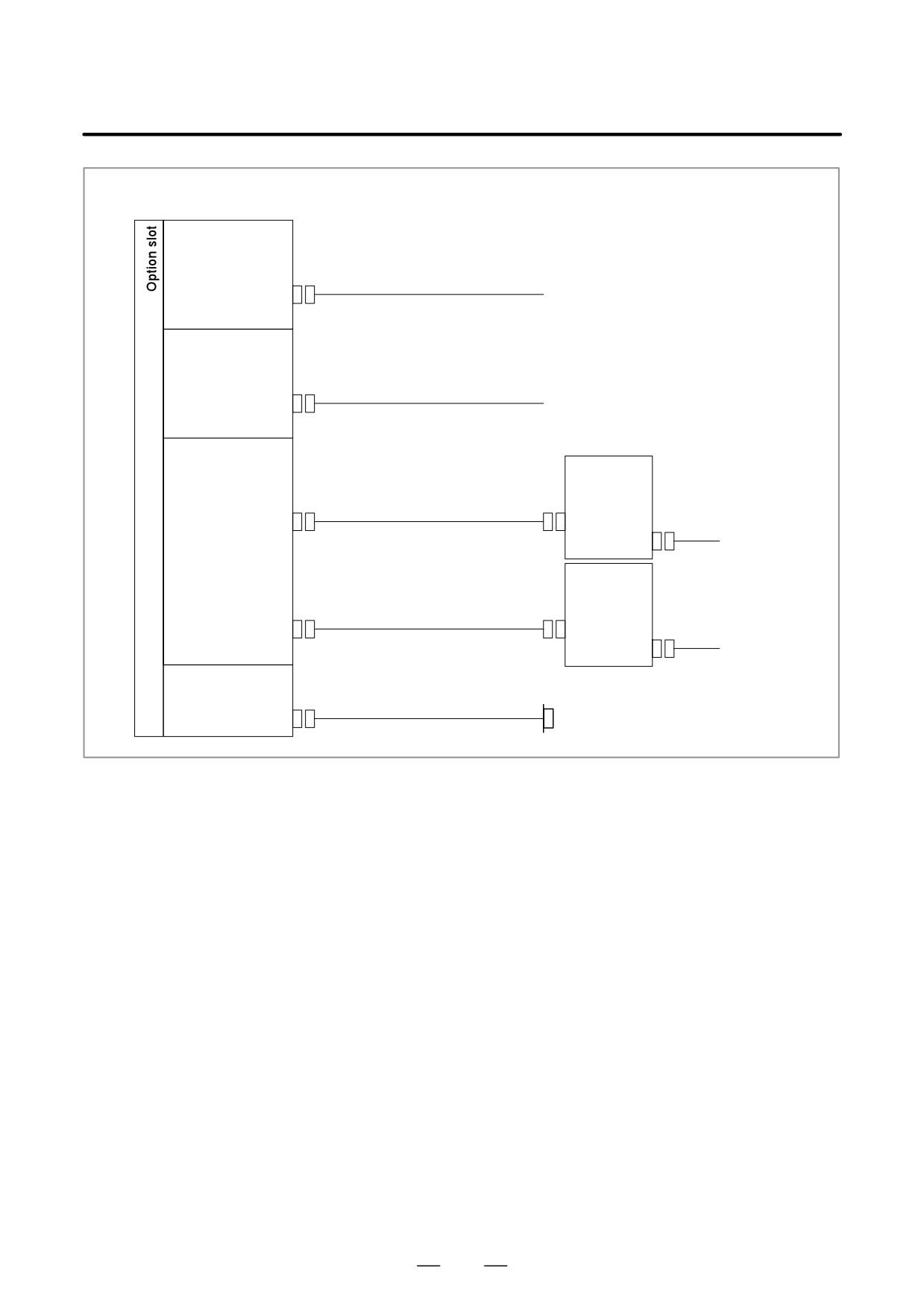
TOTAL CONNECTION DIAGRAMS
170
2.4
CONFIGURATION OF PRINTED CIRCUIT BOARD
CONNECTORS AND CARDS
175
2.5
LIST OF UNITS AND PRINTED
CIRCUIT BOARDS
221
2.6
REPLACING THE MOTHERBOARD
229
2.7
REPLACING FUSE ON CONTROL UNIT
231
2.8
REPLACING BATTERY
232
2.9
REPLACING FAN MOTORS
236
2.10 REPLACING LCD BACKLIGHT
239
2.11 HEAT GENERATED IN EACH UNIT
243
164
2. LCD-MOUNTED TYPE i SERIES
B-63525EN/02
HARDWARE
2.1
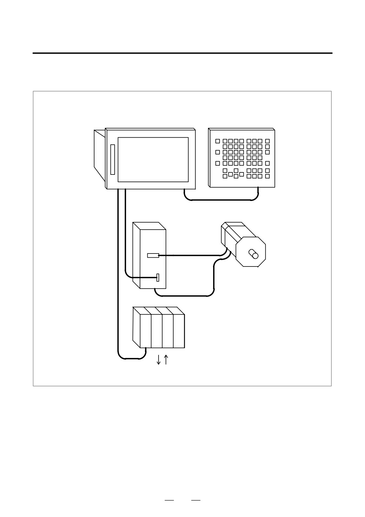
STRUCTURE
Control/LCD unit
MDI unit
Optical cable
Servo motor
Servo amplifier
I/O Link
I/O module, I/O unit MODEL-A
Machine operator’s panel/
Power magnetic circuit etc.
165
2. LCD-MOUNTED TYPE i SERIES
HARDWARE
B-63525EN/02
2.2
OVERVIEW OF
HARDWARE
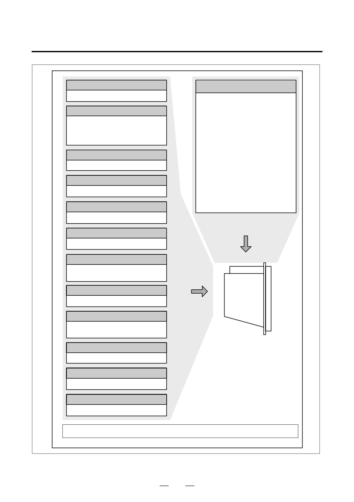
2.2.1
Series 16i/160is
166
2. LCD-MOUNTED TYPE i SERIES
B-63525EN/02
HARDWARE
Serial communication board
Motherboard
Remote buffer/DNC1/DNC2
CPU for CNC control
⋅
Power supply
Sub-CPU board
⋅
2-axis to 8-axis control
⋅
Spindle control
Sub-CPU for 2-path control
⋅
LCD/MDI interface
⋅
2-axis to 8-axis control
⋅
I/O Link
⋅ Spindle interface
⋅
PMC-SB7
⋅ Analog output
⋅
Analog output (option)
⋅
High-speed DI
⋅
RS-232C x 2
C board
⋅
Memory card interface
C function for PMC
⋅
Ethernet
Symbol CAPi T board (Only T series)
Graphic conversation function
RISC board (Only M series)
High-precision contour control function
Basic system
Data server board
Data server function
Loader control board
Loader control function
2-axis/4-axis control
I/O Link-II board
I/O Link-II interface
Option
HSSB interface board
High-speed serial interface
Without slots, or
Ethernet board
with 2 slots, or
Ethernet interface
with 3 slots, or
with 4 slots
DeviceNet interface board
DeviceNet interface
PROFIBUS board
PROFIBUS function
On a unit with option slots, as many option boards as the number of option slots can be mounted.
However, some option slots accept only specific option boards.
167
2. LCD-MOUNTED TYPE i SERIES
HARDWARE
B-63525EN/02
2.2.2
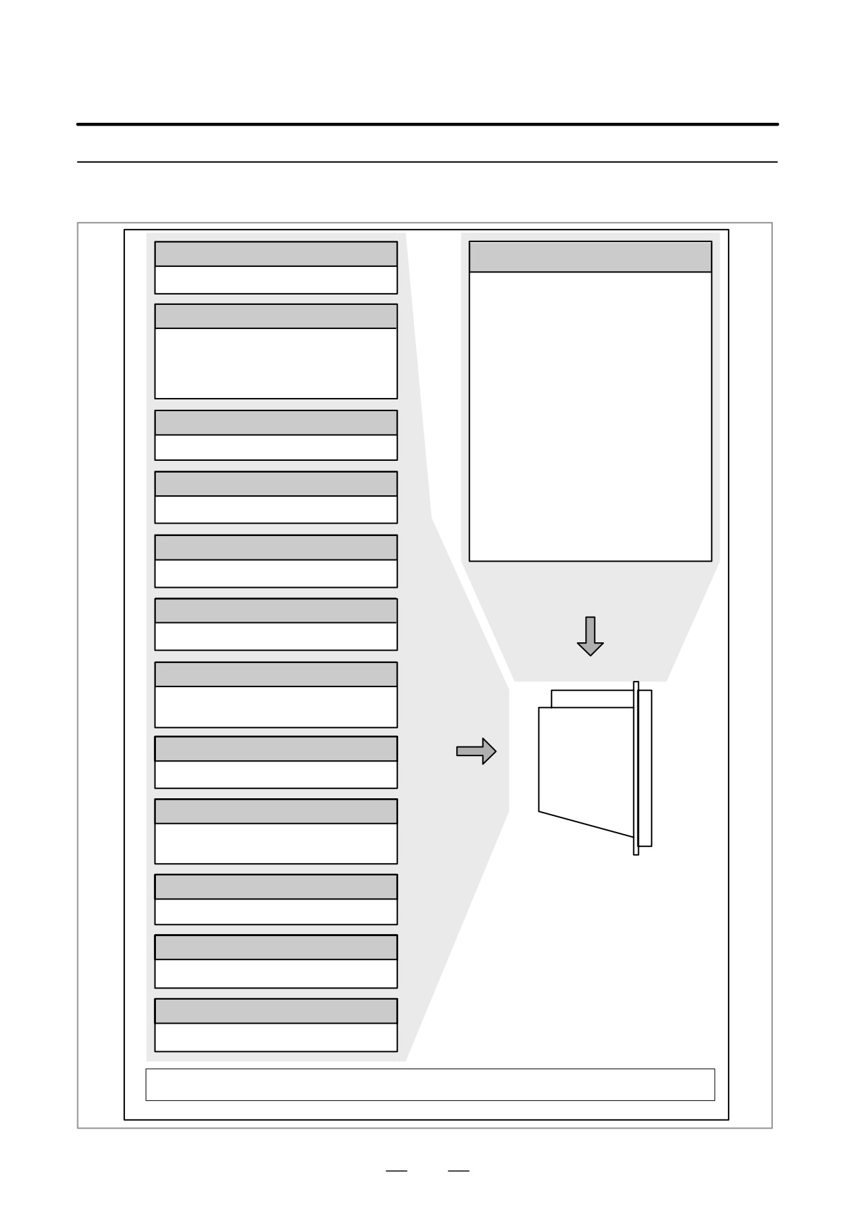
Series 18i/180is
Serial communication board
Motherboard
Remote buffer/DNC1/DNC2
CPU for CNC control
⋅
Power supply
Sub-CPU board
⋅
2-axis to 6-axis control
⋅
Spindle control
Sub-CPU for 2-path control
⋅
LCD/MDI interface
⋅
2-axis to 6-axis control
⋅
I/O Link
⋅ Spindle interface
⋅
PMC-SB7
⋅ Analog output
⋅
Analog output (option)
⋅
High-speed DI
⋅
RS-232C x 2
C board
⋅
Memory card interface
C function for PMC
⋅
Ethernet
Symbol CAPi T board (Only T series)
Graphic conversation function
RISC board (Only M series)
High-precision contour control function
Basic system
Data server board
Data server function
Loader control board
Loader control function
2-axis/4-axis control
I/O Link-II board
I/O Link-II interface
Option
HSSB interface board
High-speed serial interface
Ethernet board
Without slots, or
Ethernet interface
with 2 slots, or
with 3 slots, or
DeviceNet interface board
with 4 slots
DeviceNet interface
PROFIBUS board
PROFIBUS function
On a unit with option slots, as many option boards as the number of option slots can be mounted.
However, some option slots accept only specific option boards.
168
2. LCD-MOUNTED TYPE i SERIES
B-63525EN/02
HARDWARE
2.2.3
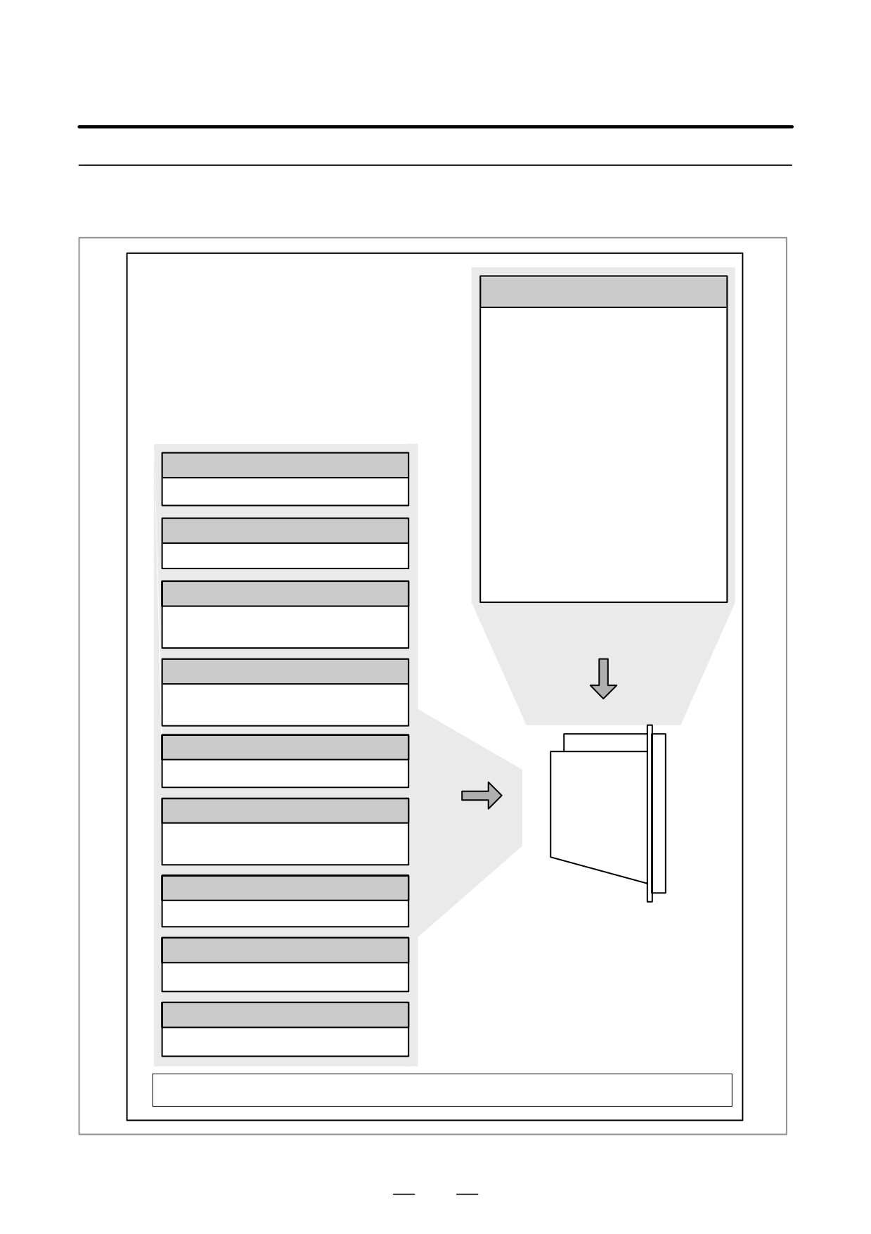
Series 21i/210is
Motherboard
CPU for controlling CNC
⋅
Power supply
⋅
2-axis to 4-axis control
⋅
Spindle interface
⋅
LCD/MDI interface
⋅
I/O Link
⋅
PMC-SB7
⋅
Analog output (option)
⋅
High-speed DI
⋅
RS-232C × 2
Serial communication board
⋅
Memory card interface
⋅
Ethernet (option)
Remote buffer/DNC1/DNC2
PMC C board
C function for PMC
Symbol CAPi T board
Graphic conversation
Basic system
(for 21i-T only)
Loader control board
Loader control function
2-axis/4-axis control
I/O Link-II board
I/O Link-II interface
HSSB interface board
Option
High-speed serial interface
Ethernet board
Ethernet interface
Unit without option
slots or unit having
DeviceNet interface board
two option slots
DeviceNet interface
PROFIBUS board
PROFIBUS function
On a unit with option slots, as many option boards as the number of option slots can be mounted.
However, some option slots accept only specific option boards.
169
2. LCD-MOUNTED TYPE i SERIES
HARDWARE
B-63525EN/02
2.3
TOTAL CONNECTION
DIAGRAMS
170
2. LCD-MOUNTED TYPE i SERIES
B-63525EN/02
HARDWARE
Common to 16i/18i/21i/160is/180is/210is
Motherboard
24V-IN(CP1A)
24 VDC power
Soft key cable
MDI UNIT
CK2
MDI(CA55)
CK1
R232(JD36A)
RS-232C I/O unit
R232(JD36B)
RS-232C I/O unit
{
Touch panel
Analog output for tool drive
A-OUT&HDI(JA40)
High-speed skip input
Distributed
I/O
Manual pulse generator
board
24VDC
CPD1
JA3
I/O Link(JD44A)
JD1B
Operator’s
panel
JD1A
24VDC
CPD1
Distributed I/O
board
Power
JD1B
magnetics
I/O UNIT
JD1A
cabinet
I/O unit, etc.
Position coder for
SPDL&POS(JA41)
analog spindle
Circuit breaker
200VAC
AC reactor
200VAC
MCC
Circuit breaker
CX3
CX1A TB2
PSM CX4
CX1B TB1
JX1B
Position coder
CX1A
TB1
CX2A JX1A
JA7B
SPM
JY2
TB2
JA7A TB1
CX2B JX1B
To 2nd spindle
Serial spindle motor
TB1
CX2A JX1A
COP10B
Axis 1 servo motor
FSSB(COP10A-1)
SVM
TB2
COP10A
JF1
TB1
CX2B JX1B
COP10B
Axis 2 servo motor
FSSB(COP10A-2)
SVM
COP10A
COP10B
Axis 3 servo motor
SVM
COP10A
COP10B
Axis 4 servo motor
SVM
COP10A
Up to four to eight axes, depending on the model (In this figure, a 1-axis amplifier is used.)
Separate detector interface unit 1
24VDC
CP11A
JF101
Linear scale, axis 1
JF102
Linear scale, axis 2
COP10B
JF103
Linear scale, axis 3
COP10A JF104
Linear scale, axis 4
CNF1
JA4A
Battery for absolute scale
(Required only when an absolute scale is used)
Separate detector interface unit 2 (cannot be used in the 21i/210is)
CP11A JF101
Linear scale, axis 1
JF102
Linear scale, axis 2
JF103
Linear scale, axis 3
JF104
Linear scale, axis 4
ETHERNET(CD38A)
Note) See Chapter 3 for connecting
Ethernet
the PC functions of the
SV-CHK(CA69)
Servo check board
160is/180is/210is.
171
2. LCD-MOUNTED TYPE i SERIES
HARDWARE
B-63525EN/02
When option boards are provided
Serial communication
board
Remote buffer board
DNC1 board
DNC2 board
R232-3(JD28A)
RS-232C I/O unit
(when remote buffer board or DNC2 board is used)
R422-1(JD6A)
RS-422 I/O unit
(when remote buffer board or DNC1 board is used)
Sub-CPU board
(cannot be used in
21i/210i)
A-OUT(JA40)
Analog output for tool drive
Position coder
SPDL&POS(JA41)
{
Position coder
PSM
Spindle motor
SPM
Servo card
To 2nd spindle
FSSB(COP10A-1)
Subaxis 1
COP10B
servo motor
SVM
FSSB(COP10A-2)
COP10A
Subaxis 2
COP10B
servo motor
SVM
COP10A
Subaxis 3
COP10B
SVM
servo motor
COP10A
Subaxis 4
COP10B
servo motor
SVM
COP10A
Up to 6 or 8-axes, depending on the model
SV-CHK(CA69)
Servo check board
172
2. LCD-MOUNTED TYPE i SERIES
B-63525EN/02
HARDWARE
When option boards are provided
Circuit breaker
Loader control board
200VAC
AC reactor
200VAC
MCC
Circuit breaker
CX1A TB2
CX3
PSM
CX4
CX1B TB1
CX2B JX1B
TB2
CX2A JX1A
Loader axis 1
FSSB(COP10A)
COP10B
TB2
SVM
servo motor
JF1
COP10A
TB1
CX2B JX1B
Loader axis 2
COP10B
SVM
servo motor
COP10A
Loader axis 3
COP10B
SVM
servo motor
COP10A
Loader axis 4
COP10B
SVM
servo motor
COP10A
(In this figure, a 1-axis amplifier is used.)
SV-CHK(CA69)
Loader control servo check board
Distributed I/O
board
24VDC
JA3
CPD1
Operator’s
I/O Link(JD1A)
JD1B
panel for
JD1A
loader
24VDC
CPD1
Distributed I/O
Power
board
JD1B
magnetics
I/O unit, etc.
JD1A
cabinet
Data server board
ATA card
The user should have the ATA card ready.
10BASET(CD38)
Ethernet
HSSB board
(When an PANEL i or PC is connected
HSSB(COP7)
PC or PANEL i
using the HSSB interface, the model
name is 16i/18i/21i.)
173
2. LCD-MOUNTED TYPE i SERIES
HARDWARE
B-63525EN/02
When option boards are provided
I/O link II board
(TB1)
To other equipment
DeviceNet board
(TB1)
To other equipment
PROFIBUS board
PROFIBUS
adapter unit
Master(JN1)
JN2
To other
CN1
equipment
PROFIBUS
adapter unit
Slave(JN2)
JN2
To other
CN1
equipment
Ethernet board
10BASET(CD38)
Ethernet
174
2. LCD-MOUNTED TYPE i SERIES
B-63525EN/02
HARDWARE
2.4
CONFIGURATION OF
PRINTED CIRCUIT
BOARD
CONNECTORS
AND CARDS
2.4.1
FS16i/18i/21i
Motherboard
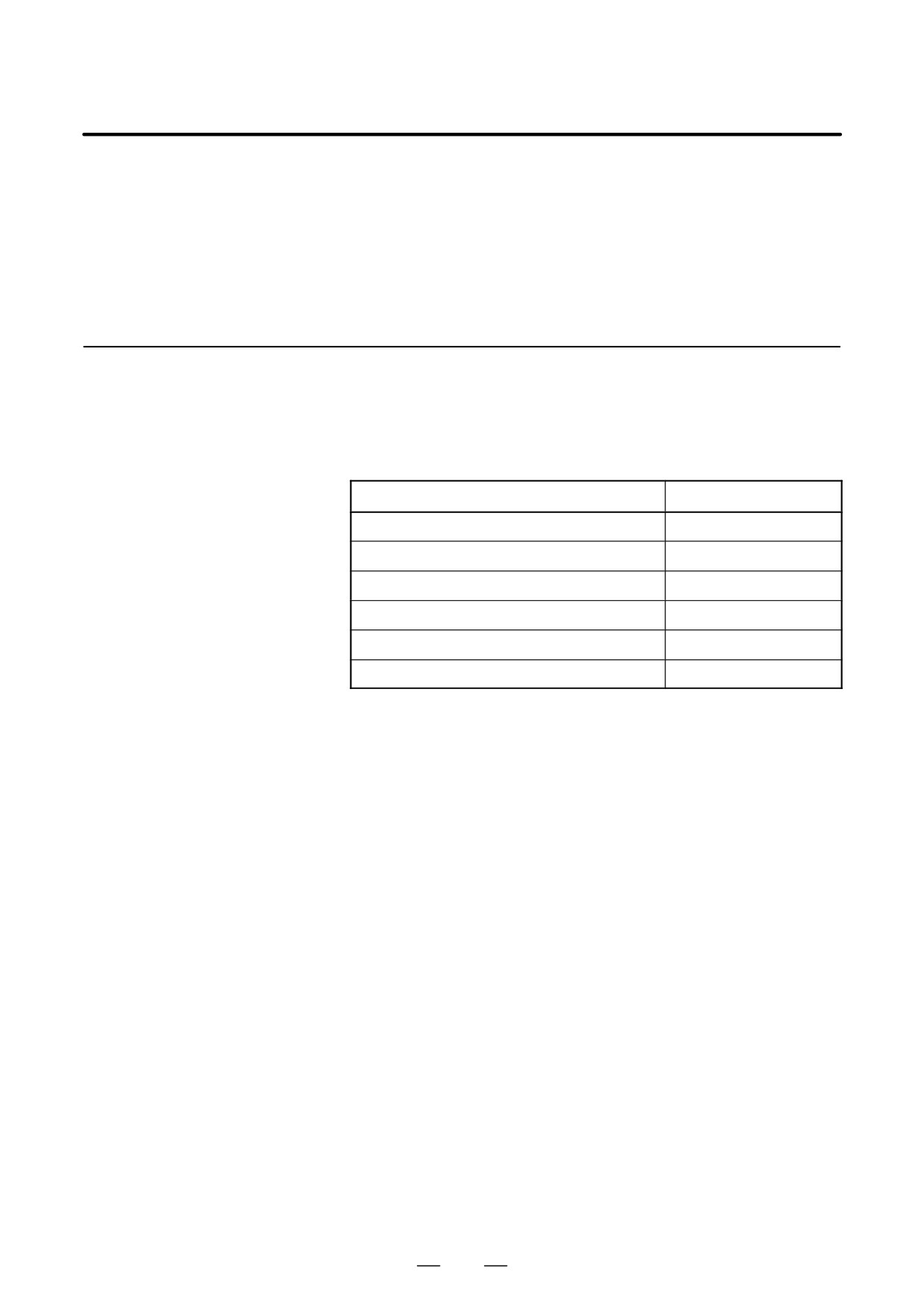
D Specification
Name
Specification
Series 16i
A20B-8100-0660
Series 18i
A20B-8100-0661
Series 21i (without Ethernet function, PMC-SA1)
A20B-8100-0662
Series 21i (without Ethernet function, PMC-SB7)
A20B-8100-0663
Series 21i (with Ethernet function, PMC-SA1)
A20B-8100-0664
Series 21i (with Ethernet function, PMC-SB7)
A20B-8100-0665
175
2. LCD-MOUNTED TYPE i SERIES
HARDWARE
B-63525EN/02
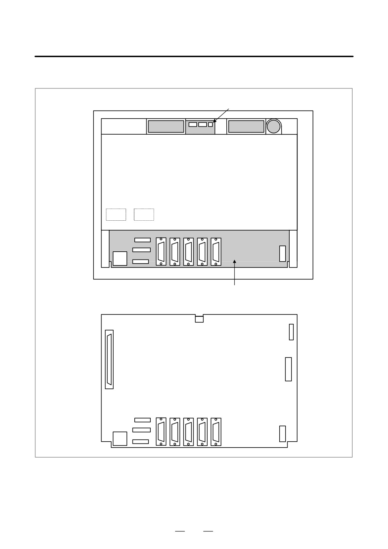
D Connector mounting
location
Connector unit
Fan motor
Fan motor
Battery
Rear of unit
COP10A-1 COP10A-2
(COP10A is a connector installed on the servo card.)
CA69
JD36A
JA40
JA41
CP1
CA55
CD38
CN2
JD36B
JD44A
Motherboard
CN3
CN8
JNA
CNM1A
Motherboard
CA69
JD36A
JA40
JA41
CP1
CA55
CD38
CN2
JD36B
JD44A
176
2. LCD-MOUNTED TYPE i SERIES
B-63525EN/02
HARDWARE
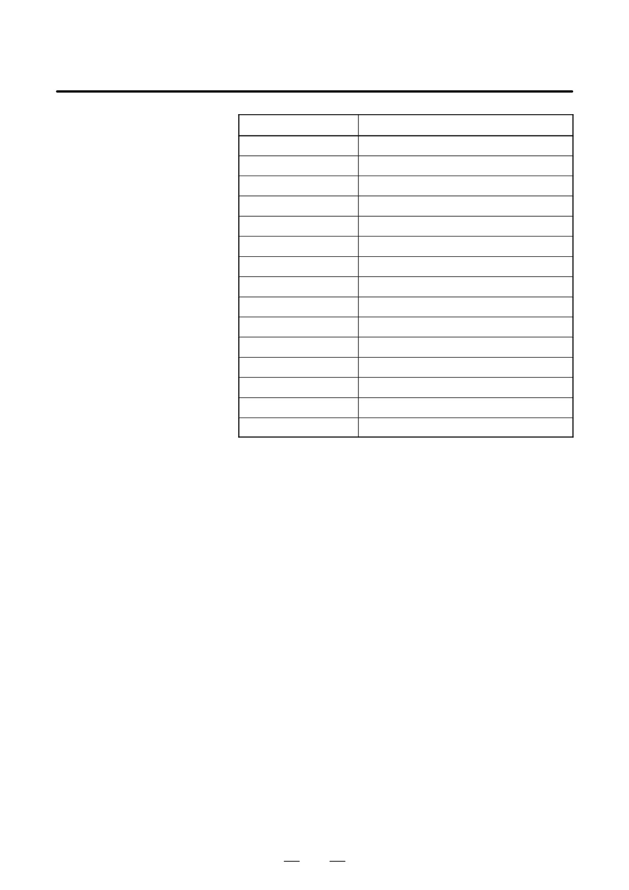
Connector number
Application
COP10A-1, COP10A-2
Servo amplifier (FSSB)
CA55
MDI
CA69
Servo check
JD36A
RS-232C serial port
JD36B
RS-232C serial port
JA40
Analog output/high-speed DI
JD44A
I/O link
JA41
Serial spindle/position coder
CP1
24VDC-IN
JNA
F-BUS interface
CN8
Video signal interface
CNM1A
PCMCIA interface
CN2
Soft key
CN3
Inverter
CD38A
Ethernet
177
2. LCD-MOUNTED TYPE i SERIES
HARDWARE
B-63525EN/02
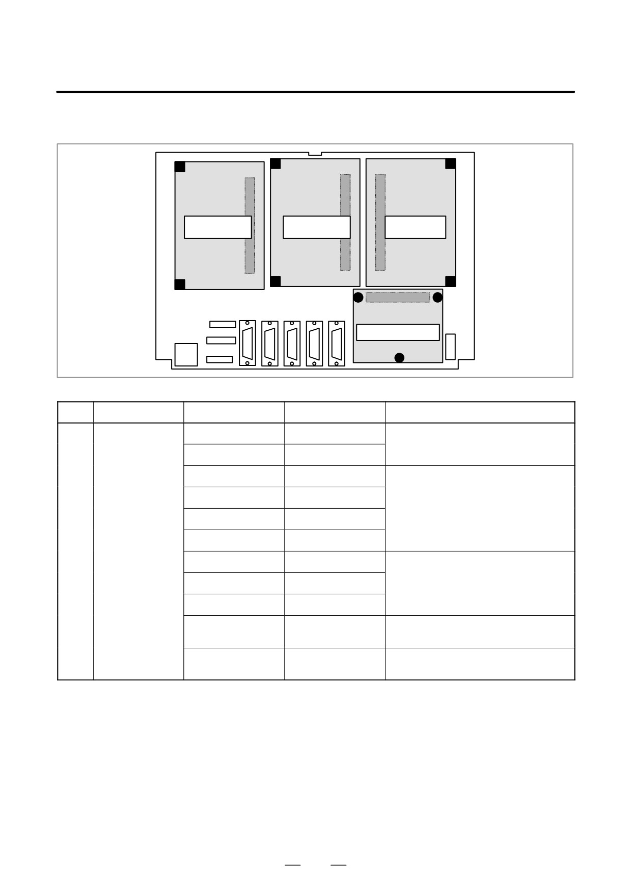
D Card and power supply
mounting location
Connector
Connector
Connector
(1) Axis control
(2) Display
(3) CPU card
card
control card
Connector
(4) Power supply unit
No.
Name
Specification
Function
Remarks
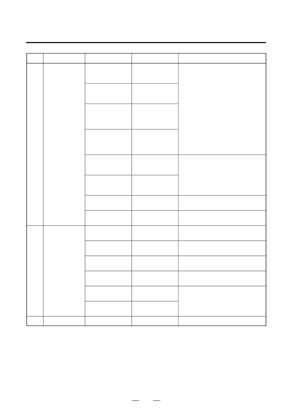
(1)
Axis control card
A20B-3300-0033
Axis control 2 axes
Applicable servo software: Series 9090
(21i)
A20B-3300-0032
Axis control 4 axes
A20B-3300-0243
Axis control 2 axes
Applicable servo software: Series 90B0
A20B-3300-0242
Axis control 4 axes
A20B-3300-0241
Axis control 6 axes
A20B-3300-0240
Axis control 8 axes
A20B-3300-0248
Axis control 4 axes
Applicable servo software: Series 90B0
(High-speed HRV)
A20B-3300-0245
Axis control 6 axes
A20B-3300-0244
Axis control 8 axes
A20B-3300-0246
Learning-control axis
Applicable servo software: Series
control
90B3/90B7
A20B-3300-0247
Learning-control axis
Applicable servo software: Series
control
90B3/90B7 (High-speed HRV)
178
2. LCD-MOUNTED TYPE i SERIES
B-63525EN/02
HARDWARE
No.
Name
Specification
Function
Remarks
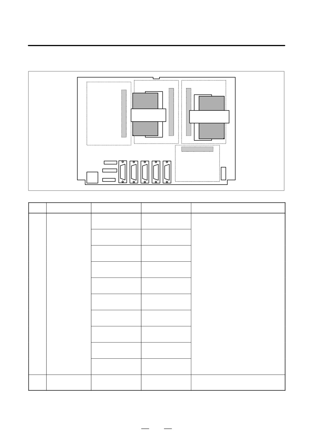
(2)
Display control
A20B-3300-0280
10.4″ color LCD with
Graphic software 60V6 series, embedded
card
graphic function and
Ethernet control software series 656A
embedded ethernet
A20B-3300-0281
8.4″ color LCD with
graphic function and
embedded ethernet
A20B-3300-0282
9.5″ monochrome
LCD with graphic
function and
embedded ethernet
A20B-3300-0283
7.2″ monochrome
LCD with graphic
function and
embedded ethernet
A20B-3300-0300
9.5″ monochrome
Embedded Ethernet control software
LCD with embedded
series 656A
ethernet
A20B-3300-0301
7.2″ monochrome
LCD with embedded
ethernet
A20B-3300-0302
9.5″ monochrome
LCD
A20B-3300-0303
7.2″ monochrome
LCD
(3)
CPU card
A20B-3300-0310
DRAM 16MB for
Series 16i/18i
A20B-3300-0311
DRAM 32MB for
Series 16i/18i
A20B-3300-0291
DRAM 16MB for
Series 21i
A20B-3300-0290
DRAM 32MB for
Series 21i
A20B-3300-0312
DRAM 16MB for
When embedded ethernet function is used
Series 21i
with Series 21i
A20B-3300-0313
DRAM 32MB for
Series 21i
(4)
Power supply unit
A20B-8100-0720
179
2. LCD-MOUNTED TYPE i SERIES
HARDWARE
B-63525EN/02
D DIMM module mounting
location
DIMM
module socket
(1) FROM/SRAM
(2) Analog spindle
module
module
DIMM
module socket
No.
Name
Specification
Function
Remarks
(1)
FROM/SRAM
A20B-3900-0160
FROM 16MB
Various control software programs are
module
SRAM 1MB
stored in the FROM module.
The SRAM is a battery-backed memory
A20B-3900-0161
FROM 16MB
module.
SRAM 2MB
A20B-3900-0162
FROM 16MB
SRAM 3MB
A20B-3900-0163
FROM 32MB
SRAM 1MB
A20B-3900-0164
FROM 32MB
SRAM 2MB
A20B-3900-0165
FROM 32MB
SRAM 3MB
A20B-3900-0180
FROM 16MB
SRAM 256kB
A20B-3900-0181
FROM 16MB
SRAM 512kB
A20B-3900-0182
FROM 32MB
SRAM 256kB
A20B-3900-0183
FROM 32MB
SRAM 512kB
(2)
Analog spindle
A20B-3900-0170
Analog spindle
module
position coder
180
2. LCD-MOUNTED TYPE i SERIES
B-63525EN/02
HARDWARE
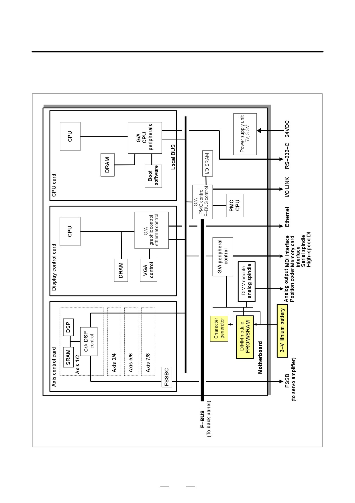
D Block diagram
181