FANUC Series 16i/160i/160is-MODEL B, Series 18i/180i/180is-MODEL B, Series 21i/210i/210is-MODEL B. MAINTENANCE MANAUL - page 6
1. DISPLAY AND OPERATION
B-63525EN/02
Function
KEY
PWE
Func-
Mode
Operation
SW
=1
tion key
Re-drawing
of “SOLID
Press the
GRAPH
key several times ³ “SOLID GRAPHIC
GRAPHIC
(PARAME-
GRAPH
(PARAMETER)” screen ³ [REVIEW] ³ [(OPRT)] ³ [ ANEW ] ³
TER)” in a
different
[+ ROT ][- ROT ][+TILT ][-TILT ]
orientation
3-plane
Press the
GRAPH
key several times ³ “SOLID GRAPHIC
drawing
GRAPH
(PARAMETER)” screen ³ [ "] ³ [3-PLN ] ³ [(OPRT)] ³ [
]
[²][³][°][±]
NOTE
For the small-size MDI, read the
GRAPH
function key in this
CUSTOM
table as the
GRAPH
function key.
Help function
KEY
PWE
Func-
Function
Mode
Operation
SW
=1
tion key
Initial menu
screen dis-
HELP
HELP
play
Alarm detail
screen dis-
HELP
[ALARM ] ³ Alarm No. ³ [SELECT]
play
Operation
method
HELP
[OPERAT] ³ Operation method item No. ³ [SELECT]
screen dis-
play
Parameter
table-of-con-
HELP
[PARAM]
tents screen
display
Self-diagnosis function
KEY
PWE
Func-
Function
Mode
Operation
SW
=1
tion key
[DGNOS ]
Self-diagno-
±
sis screen
SYSTEM
1.
PAGE
page switch keys
display
PAGE
2. Diagnosis data No. ³ [NO.SRH]
122
B-63525EN/02
1. DISPLAY AND OPERATION
Boot
KEY
PWE
Func-
Function
Mode
Operation
SW
=1
tion key
System mon-
Pow-
itor screen
er-on
—
and a soft key at its left
display
time
Reading file
Place the cursor at 1. SYSTEM DATA LOADING on the system monitor
from memory
screen ³ [SELECT] ³ Place the cursor at the target file ³ [SELECT]
card
³ [YES]
Listing files in
flash ROM
Place the cursor at 2. SYSTEM DATA CHECK on the system monitor
and display-
screen ³ [SELECT] ³ Place the cursor at the target item ³ [SELECT]
ing detail
screen
Deleting file
Place the cursor at 3. SYSTEM DATA DELETE on the system monitor
from flash
screen ³ [SELECT] ³ Place the cursor at the target file ³ [SELECT]
ROM
³ [YES]
Outputting
Place the cursor at 4. SYSTEM DATA SAVE on the system monitor
file from flash
screen ³ [SELECT] ³ Place the cursor at the target file ³ [SELECT]
ROM to
³ [YES]
memory card
Place the cursor at 5. SRAM DATA BACKUP on the system monitor
Transferring
screen ³ [SELECT]
contents be-
- Batch output to memory card
tween SRAM
Place the cursor at 1. SRAM BACK UP ³ [SELECT] ³ [YES]
and memory
- Batch input from memory card
card in batch
Place the cursor at 2. RESTORE SRAM ³ [SELECT] ³ [YES]
Deleting file
Place the cursor at 6. MEMORY CARD FILE DELETE on the system
from memory
monitor screen ³ [SELECT] ³ Place the cursor at the target file ³
card
[SELECT] ³ [YES]
Memory card
Place the cursor at 7. MEMORY CARD FORMAT on the system moni-
formatting
tor screen ³ [SELECT] ³ [YES]
Exiting sys-
Place the cursor at 10. END on the system monitor screen
tem monitor
³ [SELECT] ³ [YES]
Reference
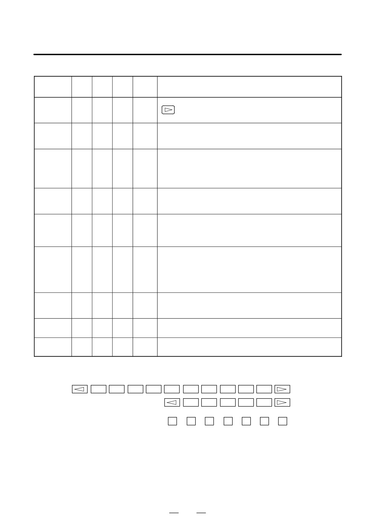
If no soft key is available as with a touch panel, use the numeric keys on
the MDI keypad.
: 12-soft key type
: 7-soft key type
±
±
±
±
±
±
±
1
2
3
4
5
6
7
123

1. DISPLAY AND OPERATION
B-63525EN/02
1.13
WARNING SCREEN
DISPLAYED WHEN
AN OPTION IS
CHANGED
D Warning screen
This CNC displays a warning screen when the configuration of the
options using the SRAM area is changed. The data for the function
indicated on the screen is cleared the next time the system is turned on.
WARNING
YOU SET THE PARAMETER NO.jjjj#j
THE FOLLOWING DATA WILL BE CLEARED.
* PART PROGRAM MEMORY
PLEASE PRESS <DELETE> OR <CAN> KEY.
<DELETE> : CLEAR ALL DATA
<CAN>
: CANCEL
NOTE
Mark* varies with the parameter settings. Two or more
function names may be displayed.
124
B-63525EN/02
1. DISPLAY AND OPERATION
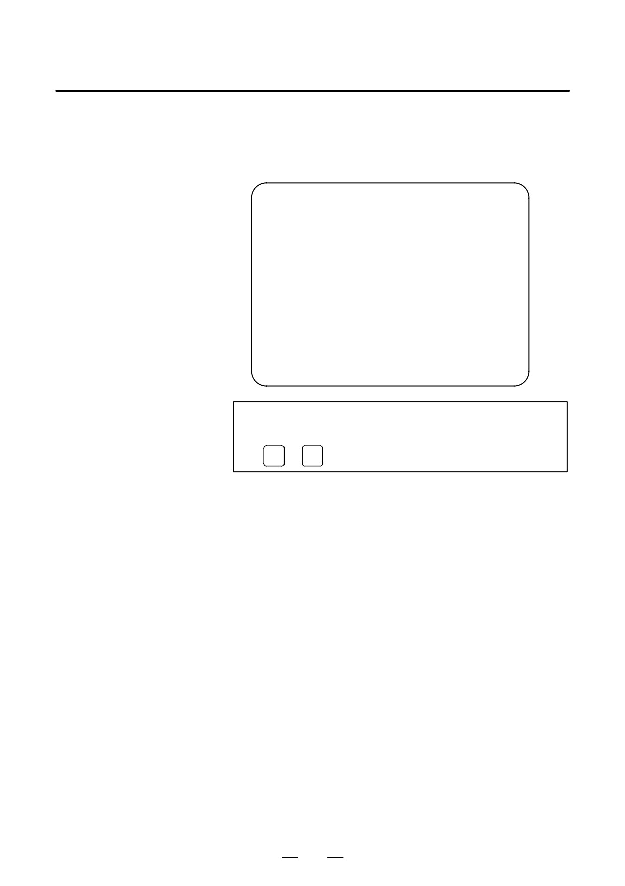
D Allocation error screen
When an option which uses the SRAM area is added, the system software
may require more SRAM than is currently installed in the system. In this
case, an allocation error screen appears the first time the system is turned
on after the addition of the option, thus restoring the state existing before
the addition.
FILE ALLOCATION ERROR
S-RAM CAPACITY IS NOT SUFFICIENT.
ADDITIONAL S-RAM IS NECESSARY.
PLEASE PRESS <CAN> KEY :
RETURN TO THE STATE BEFORE
OPTION PARAMETER IS CHANGED.
NOTE
When replacing SRAM, perform all memory clear.
(
RESET
+
DELETE
)
125

1. DISPLAY AND OPERATION
B-63525EN/02
When an attempt is made to turn on the power to the CNC after replacing
1.14
the system software, the screen shown below is displayed, and the system
WARNING SCREEN
is not started if the replacing new system software is not compatible with
DISPLAYED WHEN
the replaced system software.
SYSTEM SOFTWARE
IS REPLACED
(SYSTEM LABEL
CHECK ERROR)
BOH1-01
SYSTEM LABEL CHECK ERROR:
CLEAR ALL SRAM MODULE
NOT READY
In this case, perform memory all clear (by holding down the
RESET
and
DELETE
MDI keys then turning on the power) or reinstall the original system
software.
126
B-63525EN/02
1. DISPLAY AND OPERATION
The maintenance information screen is provided to record the history of
1.15
maintenance performed by a service person of FANUC or machine tool
MAINTENANCE
builder.
INFORMATION
The screen has the following features:
SCREEN
D MDI alphabetical input is allowed.
D The recording screen can be scrolled in units of lines.
D Edited maintenance information can be read and punched.
D The screen can be saved in flash ROM.
1.15.1
Screen Display and
Operation
D Screen display
1. Press the
SYSTEM
function key.
2. Press the continuous menu key
several times. [M-INFO] soft
key appears.
3. Press the [M-INFO] soft key. The maintenance information screen
appears.
When selected, the maintenance screen shows the latest information.
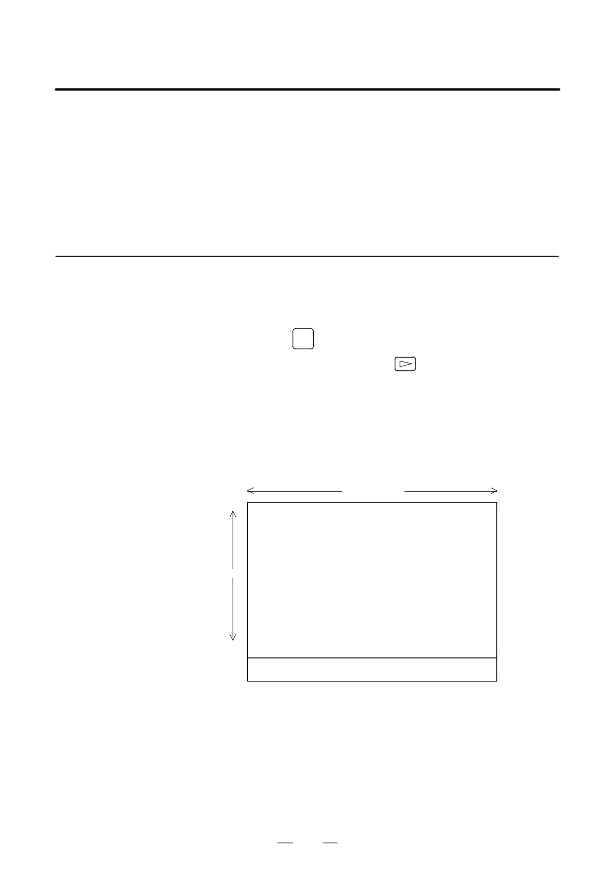
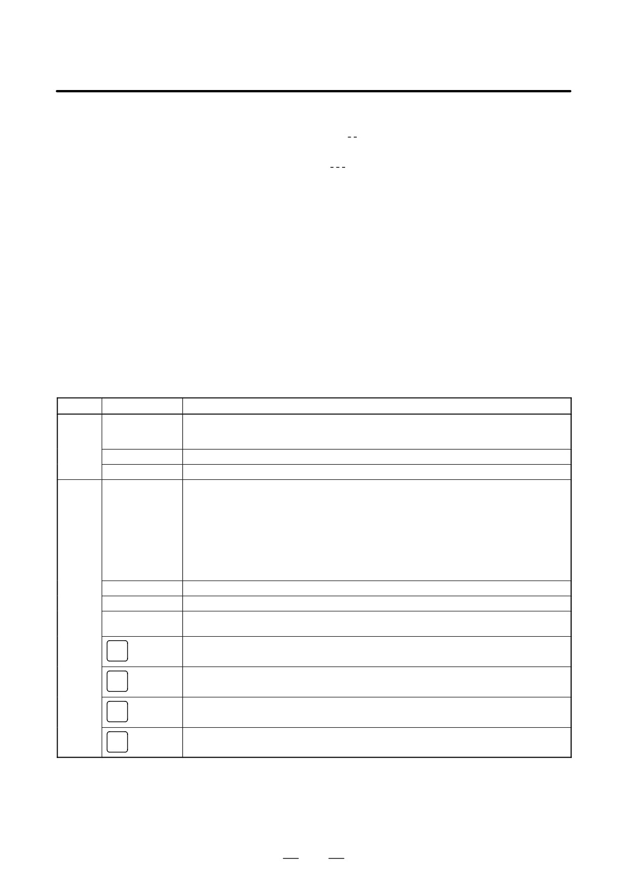
The recording screen has an input area of 40 characters by 11 lines.
The status (mode, number of empty character spaces, cursor line, column
number) is displayed at the bottom of the screen.
40 characters
MAINTENANCE INFORM
aaa
bbb
ccc
ddd
11
lines
eee
fff
nnn
|OVER|EDIT|spaces:2078
33:1
127
1. DISPLAY AND OPERATION
B-63525EN/02
Status display
⋅ OVER/INSERT : OVER : Overwrite mode ; INSERT: Insert
mode
⋅ EDIT/VIEW :
EDIT : Editing allowed ; VIEW : Editing inhi
bited
⋅ Number of empty character spaces
⋅ Current cursor line
⋅ Current cursor column
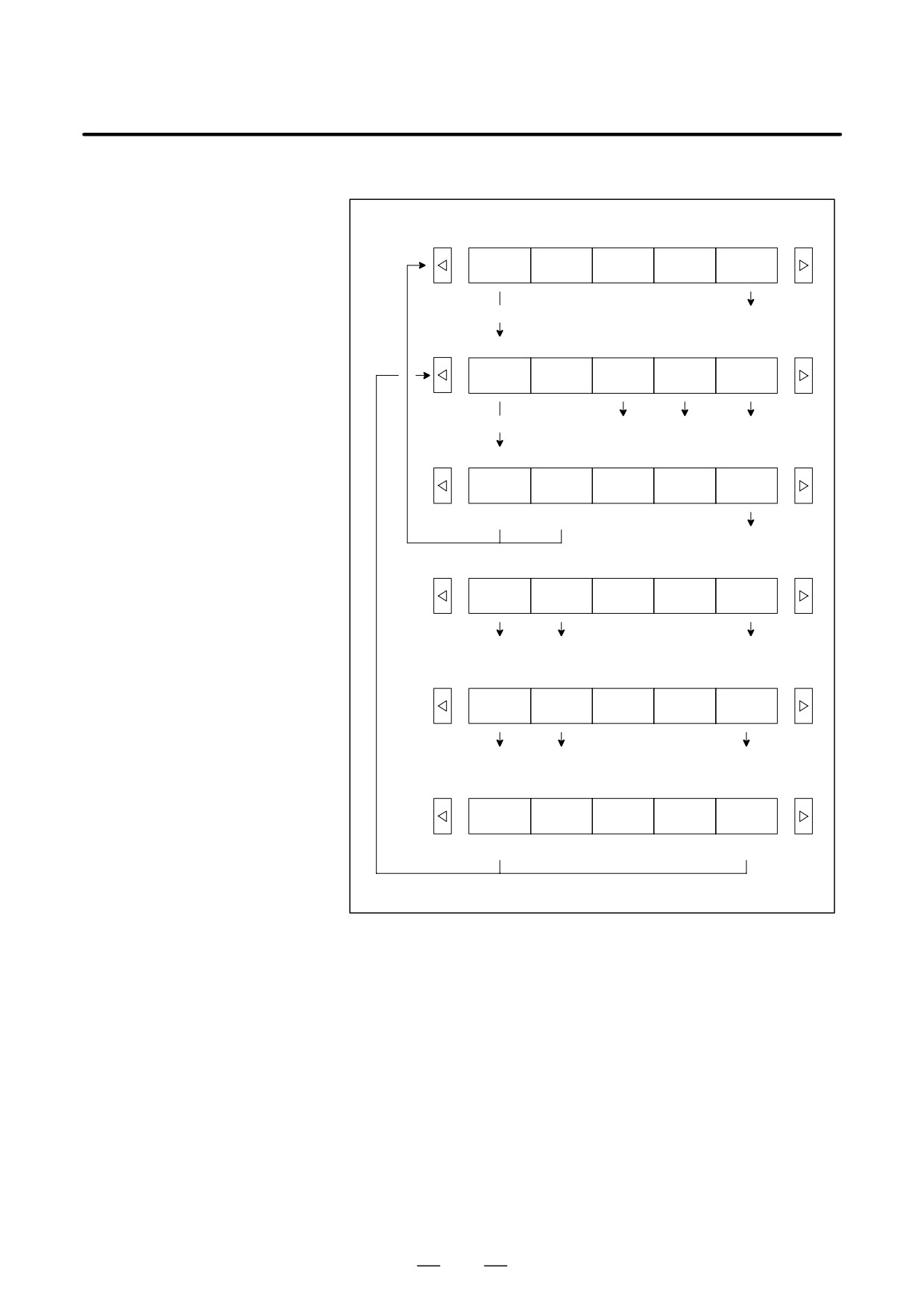
D Screen operation
The maintenance information screen has view mode and edit mode, which
are selected by pressing the [END] or [EDIT] soft key.
Initially, view mode is selected. To start editing, select edit mode by
pressing the [(OPRT)] and [EDIT] keys. When the editing is completed,
press the [END] key. Then, select [STORE] or [IGNORE]. Unless
[STORE] is selected, the edited data will be lost at next power-up.
To scroll the screen showing the recorded information, press a cursor key
or page key on the MDI panel.
The following keys are used for editing (character input) and viewing:
Operation table
Mode
Key
Description
View
Soft keys
Allows editing.
[EDIT]
Displays the beginning or the end.
[JUMP]
Cursor key
Scrolls the screen up or down.
Page key
Scrolls the screen up or down in units of whole screens.
Edit
Soft keys
[END]
Ends editing. Select whether to store the edited data.
[ALLDEL]
Clears all maintenance information. (This key is enabled when the MDC bit (bit 3 of parameter 3118) is
set to 1.)
[I/O]
Reads or punches the maintenance information.
[JUMP]
Moves the cursor to the beginning or end.
Cursor key
Moves the cursor position up or down.
Page key
Scrolls the screen up or down in units of whole screens.
Alphanumeric/spe-
Allows alphabetical, numeric, or special character input.
cial character keys
key
Selects either insert mode or overwrite mode.
INSERT
key
Deletes a single character.
DELETE
key
Deletes a single character before the cursor position.
CAN
key
Starts a new line.
INPUT
128
B-63525EN/02
1. DISPLAY AND OPERATION
Operation of the soft keys
(1)
View mode
Edit
Jump
(2)
(5)
(2)
Edit mode
END
I/O
ALLDEL
Jump
(3)
(4)
(6)
(5)
(3)
Edit saving
MAINTE-
IGNORE
CANCEL
NANCE
(1)
(1)
(2)
(4)
I/O
READ
PUNCH
CANCEL
(6)
(6)
(2)
(5)
Jump
BEGIN-
END
CANCEL
ING
(1) (2)
(1) (2)
(1) (2)
(6)
Execution
EXEC
CANCEL
(2)
(2)
129

1. DISPLAY AND OPERATION
B-63525EN/02
1.15.2
The maintenance information can be read and punched.
When the maintenance information is input from or output to a memory
Maintenance
card, a file name MAINTINF.DAT is used.
Information
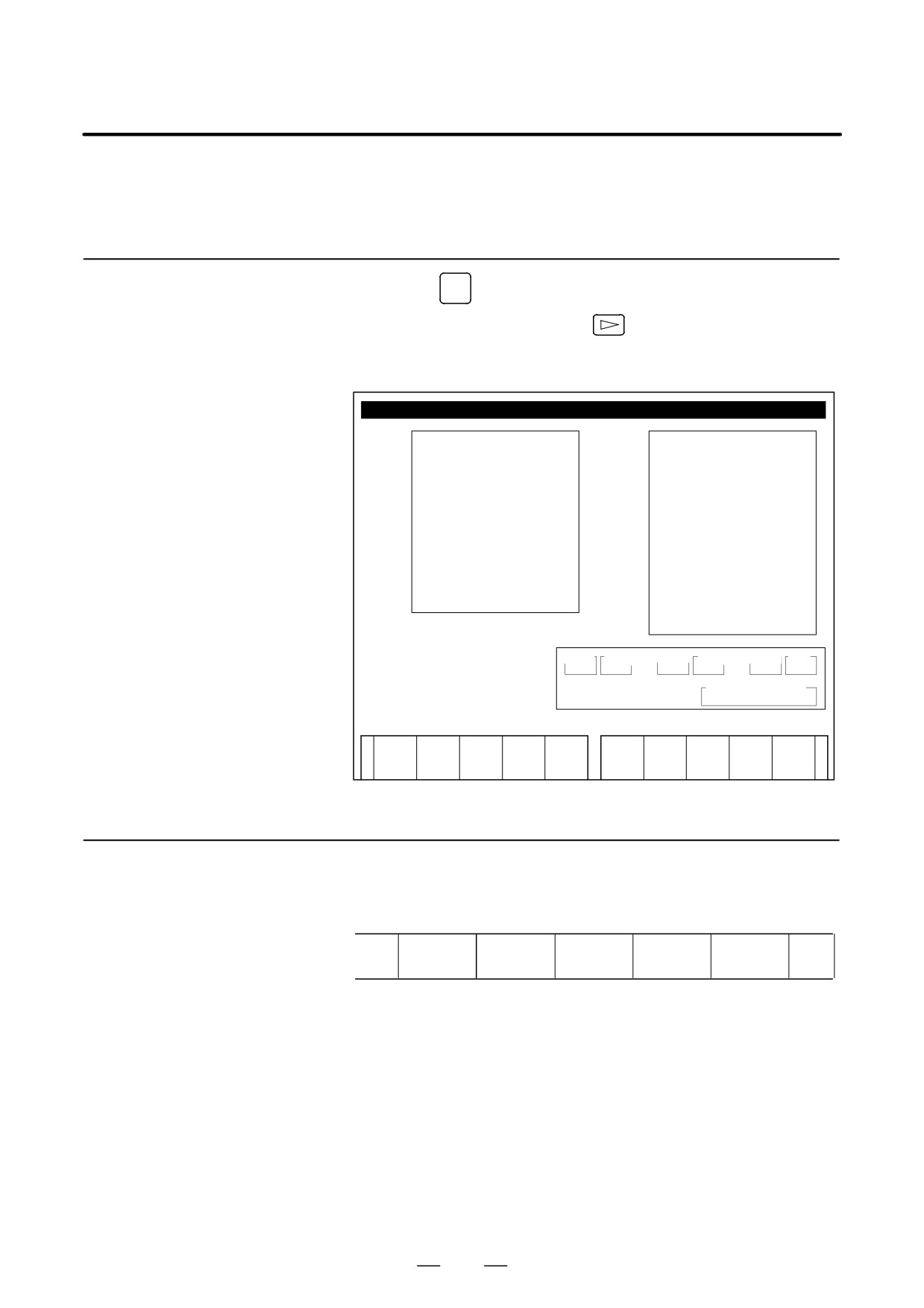
(1) Format
Input/Output
%%
Data
(2) Reading
When a MAINTINF.DAT file generated in the format shown above is
read, the data is added at the end of the existing maintenance
information.
NOTE
1
A TAB code is converted to one to four blanks, depending
on the input position.
2
80h to 90h and E0h to EBh are assumed as prefix codes of
double-byte characters. Reading these codes alone is
inhibited.
3
Control codes
(00H to 1FH) except TAB and LF are
discarded in reading.
4
%% cannot be input.
(3) Punching
All maintenance information is output in the format shown above.
130
B-63525EN/02
1. DISPLAY AND OPERATION
When VGA screen display is selected (NVG bit (bit 7 of parameter 3119)
1.16
is set to 0), the color scheme of the VGA screen can be set on the color
COLOR SETTING
setting screen.
SCREEN
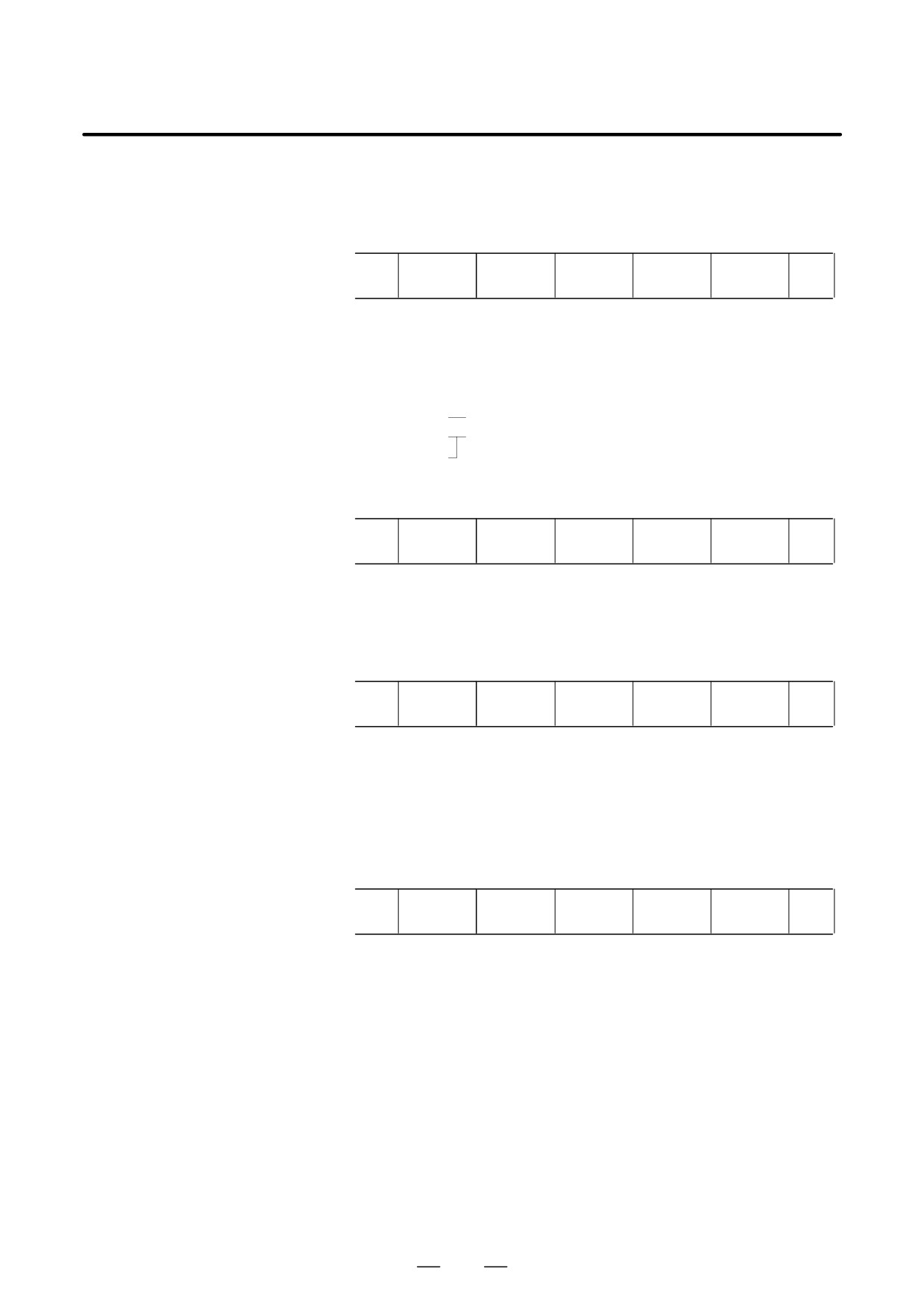
1.16.1
1.
Press the
SYSTEM
function key.
Screen Display
2.
Press the continuous menu key
several times. The [COLOR]
soft key appears.
3.
Press the [COLOR] soft key. The color setting screen appears.
COLORING
O 0 0 0 0 N 0 0 0 0 0
[
1 ]J
⋅ A LARM
8 J
⋅ SELECT WINDOW BAR
2 J
⋅ TITLE
⋅ SOFT KEY 1
9 J
⋅ NONE
3 J
⋅ INPUT KEY ⋅ O/N NO.
10 J
⋅ TITLE BAR
⋅ INPUT BAR
⋅ STATUS
4 J
⋅ CURSOR
11 J
⋅ WINDOW BACKGROUND
5 J
⋅ RESTART NO.
12 J
⋅ LIGHT
⋅ ABSOLUTE ORDER
6 J
⋅ SUB TITLE
⋅ SOFT KEY 2
13 J
⋅ ALTER POSSIBLE DATA
7 J
⋅ DATA
⋅ TIME
14 J
⋅ SHADOW
15 V
⋅ BACKGROUND
RED
08
GREEN
00
BLUE
00
1(PARAMETER)
COLOR SELECT NO.
[ MEM **** *** *** | *** | 12:34:56 |
]
COLOR
MAINTE
MAINTE
(OPRT)
+
1.16.2
Color Setting
D Changing a color
1. Press the [(OPRT)] soft key. The following operation soft keys appear.
(color palette value)
RED
GREEN
BLUE
BRIGHT
DARK
+
2. Move the cursor to the color number corresponding to the color palette
value to be changed.
The current color palette values of individual color elements are
displayed.
3. Select a desired color element by pressing the [RED], [GREEN], or
[BLUE] operation soft key.
Two or more color elements can be simultaneously selected.
Each time the [RED], [GREEN], or [BLUE] operation soft key is
pressed, the selection is made or canceled.
(If the [RED], [GREEN], and [BLUE] operation soft keys are not
displayed, press the rightmost soft key.)
131
1. DISPLAY AND OPERATION
B-63525EN/02
4. Press the [LIGHT] or [DARK] operation soft key to change the
luminance of the selected color element.
D Storing colors
A specified color palette value can be stored.
(color palette values)
STORE
CALL
COLOR1
COLOR2
COLOR3
+
1.
Select a desired storage area by pressing the [COLOR1], [COLOR2],
or [COLOR3] operation soft key.
(If the [COLOR1], [COLOR2], and [COLOR3] operation soft keys
are not displayed, press the rightmost soft key.)
COLOR1
Standard color data parameters (6561 to 6595)
COLOR2
Internal RAM
COLOR3
2.
Press the [STORE] operation soft key. The following operation soft
keys appear.
CAN
EXEC
+
3.
To store the current color palette values in the selected area, press the
[EXEC] operation soft key. To cancel the storage, press the [CAN]
operation soft key or the leftmost key.
D Calling colors
(color palette values)
STORE
CALL
COLOR1
COLOR2
COLOR3
+
1.
Select a color palette storage area by pressing the [COLOR1],
[COLOR2], or [COLOR3] operation soft key.
(If the [COLOR1], [COLOR2], and [COLOR3] operation soft keys
are not displayed, press the rightmost soft key.)
2.
Press the [CALL] operation soft key. The following operation soft
keys appear.
CAN
EXEC
+
3.
To call the color palette values from the selected area, press the
[EXEC] operation soft key. If no color palette value is stored, this step
cannot be executed.
To stop calling, press the [CAN] operation soft key or the leftmost key.
132
B-63525EN/02
1. DISPLAY AND OPERATION
1.16.3
Parameters
#7
#6
#5
#4
#3
#2
#1
#0
3119
NVG
[Data type]
Bit
NVG
When a color display unit is used, the VGA screen display is:
0 :
Selected.
1 :
Not selected.
(Conventional display)
6561
Standard color data of graphic color 1
6562
Standard color data of graphic color 2
6563
Standard color data of graphic color 3
6564
Standard color data of graphic color 4
6565
Standard color data of graphic color 5
6566
Standard color data of graphic color 6
6567
Standard color data of graphic color 7
6568
Standard color data of graphic color 8
6569
Standard color data of graphic color 9
6570
Standard color data of graphic color 10
6571
Standard color data of graphic color 11
6572
Standard color data of graphic color 12
6573
Standard color data of graphic color 13
6574
Standard color data of graphic color 14
6575
Standard color data of graphic color 15
6581
Standard color data of text color 1
6582
Standard color data of text color 2
6583
Standard color data of text color 3
6584
Standard color data of text color 4
6585
Standard color data of text color 5
6586
Standard color data of text color 6
6587
Standard color data of text color 7
6588
Standard color data of text color 8
6589
Standard color data of text color 9
133
1. DISPLAY AND OPERATION
B-63525EN/02
6590
Standard color data of text color 10
6591
Standard color data of text color 11
6592
Standard color data of text color 12
6593
Standard color data of text color 13
6594
Standard color data of text color 14
6595
Standard color data of text color 15
[Data type] Two-word
[Unit of data] Six-digit number rrggbb (rr: Red component value, gg: Green component
value, bb: Blue component value)
When five digits or less are specified, the missing high-order digits are
assumed as zeros.
[Valid data range] Each color component value: 00 to 15 (Equivalent to the color level on
the color setting screen)
When 16 or a higher value is specified, 15 is assumed.
(Example) When specifying a color having red component value 1, green
component value 2, and blue component value 3, set the
parameter value as 10203.
1.16.4
(1) At power-up, the color scheme of the screen is determined by the
setting in the COLOR1 area (parameters). If no data is stored in the
Notes
COLOR1 area, the last color scheme before power-down is applied.
(2) The standard color data specified in parameters must not be changed
by direct MDI key input. When changing the parameter data, set and
store the new data on the color setting screen.
(3) When a wrong value is specified in a standard color data parameter,
the screen may not be displayed. If this occurs, turn the power on
again, while pressing the
DELETE
and
RESET
keys. This clears the whole
stored color scheme and restores the FANUC standard color scheme
instead.
Be very careful when performing this operation, as all memory
contents such as parameters and programs are lost.
134
B-63525EN/02
1. DISPLAY AND OPERATION
Depending on the eye level and the viewing angle of the operator, the LCD
1.17
may be hard to read. This problem can be solved by adjusting the contrast.
CONTRAST
The contrast of a monochrome LCD can be adjusted.
ADJUSTMENT
OFFSET
1. Press the
SETTING
function key.
2. Press the [SETTING] chapter selection soft key.
The LCD contrast item is displayed on the setting (handy) screen.
SETTING(HANDY)
PARAMETER WRITE = 1(0:DISABLE 1: ENABLE)
TV CHECK
= 0(0:OFF 1:ON)
PUNCH CODE
= 0(0:EIA 1:ISO)
INPUT UNIT
= 0(0:MM
1:INCH)
I/O CHANNEL
= 0(0-3:CHANNEL NO.)
SEQUENCE NO.
= 0(0:OFF 1:ON)
TAPE EORMAT
= 0(0:NO CNV 1:F15)
SEQUENCE STOP
= 0(PROGRAM NO.)
SEQUENCE STOP
= 0(SEQUENCE NO.)
[ CONTRAST ]( + = [ ON:1 ] - = [ OFF:0 ])
>_
MDI **** *** *** 00:00:00
[NO.SRH] [ ON:1 ] [OFF:0] [+INPUT] [INPUT]
3. Move the cursor to “CONTRAST”.
4. Adjust the contrast by pressing the operation soft key [ON:1] or
[OFF:0].
7.2-inch Monochrome
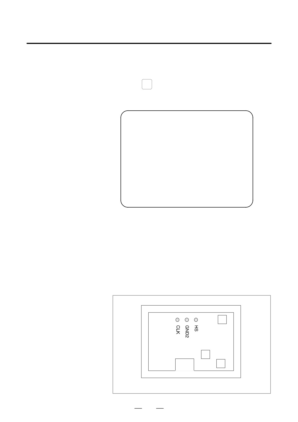
The 7.2-inch monochrome LCD (connecting using CRT Link) is
LCD (CRT Link)
provided with a contrast adjustment potentiometer and video signal
Adjustment
adjustment switches.
The contrast is adjusted when the LCD adapter or panel is replaced.
Otherwise, it should not be necessary to use the adjustment switches.
Adjustment points
VR1
VRP1
SW1
7.2-inch monochrome LCD (rear view)
135
1. DISPLAY AND OPERATION
B-63525EN/02
Adjustment procedure
(1) Contrast adjustment
Potentiometer VRP1
This adjustment is made to compensate for variations between,
individual LCD adapters and LCD panels. When an LCD adapter or
panel is replaced, the following adjustment must be made. If the entire
LCD unit is replaced, however, no adjustment is needed.
(a) First, adjust potentiometer VRP1 until the displayed characters (all
black areas) appear white.
(b) Rotate the potentiometer in the opposite direction until the
characters appear clear and black.
(2) Flicker adjustment
Potentiometer VR1
This potentiometer is factory-set and normally need not be adjusted
by the user. If the setting is changed by mistake, re-adjust it according
to the following procedure. Note that some versions of this
printed-circuit board do not have this potentiometer; adjustment is
performed automatically.
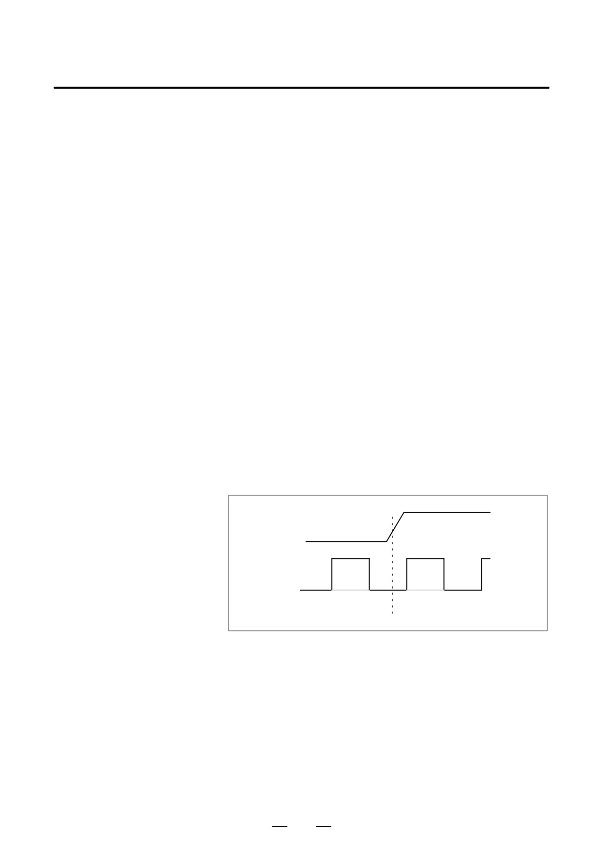
(a) Using the check pins, observe HS and CLK on an oscilloscope.
(b) Over part of the range of potentiometer VR1, the positive-going
edge of HS will be almost in phase with the positive-going edge
of the CLK. Rotating the potentiometer a little does not change the
phase difference. Set the potentiometer to the midpoint of this
range.
(c) After completing the adjustment, confirm that the display does not
flicker.
HS
CLK
(3) Horizontal position adjustment
Switch SW1
This switch is factory-set and normally need not be adjusted by the
user. If the setting is changed by mistake, re-adjust it according to the
following procedure.
(a) Switch SW1 is used to move the display horizontally in units of
dots.
(b) Set the switch to the point between 8 and B where the entire display
is visible.
(c) The default setting is 9.
136
B-63525EN/02
1. DISPLAY AND OPERATION
NOTE
If the ambient temperature is low, the brightness of the LCD
decreases (immediately after the power is turned on, in
particular). This is due to the characteristics of the LCD, and
does not indicate a fault. As the ambient temperature rises,
the LCD becomes brighter.
137
1. DISPLAY AND OPERATION
B-63525EN/02
When the Power Motion series is used as an additional axis (slave) of the
1.18
CNC, the power motion manager allows the slave data to be displayed and
POWER MOTION
set by the CNC.
MANAGER
The power motion manager enables the following display and setting:
(1) Current position display (absolute/machine coordinates)
(2) Parameter display and setting
(3) Diagnosis display
(4) System configuration screen display
(5) Alarm display
The Power Motion series that can be used as the slave is a β amplifier with
I/O Link.
1.18.1
Parameter
#7
#6
#5
#4
#3
#2
#1
#0
960
2CH
ASG
SLPWE
PMN
MD2
MD1
SLV
[Data type]
Bit
SLV
When the power motion manager is selected, the screen shows the data of:
0 : A single slave.
1 : Up to four slaves by dividing the screen into four segments.
MD1, MD2
The slave parameters are input from and output to the following devices:
MD2
MD1
I/O device
0
0
Part program storage
0
1
Memory card
The parameters are input or output in the program format, no matter which
I/O device is selected.
PMN
The power motion manager function is:
0 : Enabled.
1 : Disabled.
(Communication with the slave is not performed.)
SLPWE
The settings of slave parameters:
0 : Can be made by Power mate CNC manager regardless of the PWE
setting.
1 : Are made according to the PWE setting.
ASG
Whether or not the number of bytes allocated to the input/output
destination of the β amplifier with I/O links is 16:
0 : Is checked.
1 : Is not checked.
2CH
Power mate CNC manager:
0 : Communicates with channel 2.
1 : Communicates with channel 1.
138
B-63525EN/02
1. DISPLAY AND OPERATION
NOTE
1
The parameters are valid only when I/O link count extension
is supported (two channels are supported).
2
Even when
0 is set, Power Mate CNC Manager
communicates with channel 1 if the β amplifier with I/O links
is not connected to channel 2.
3
When 1 is set, Power Mate CNC Manager does not
communicate with channel 2 if the β amplifier with I/O links
is not connected to channel 1.
1.18.2
SYSTEM
1. Press the
function key.
Screen Display
2. Press the continuous menu key
several times. The [PMM] soft
key appears.
3. Press the [PMM] soft key. The system configuration screen, which is
the initial screen of the power motion manager, appears. The screen
has the following soft keys (function selection soft keys).
[ POS
][
][
][SYSTEM][ MSG
]
The currently active soft key is displayed in reverse video. Pressing a soft
key enables the corresponding function, as indicated below:
POS: Current position display
SYSTEM: System information
MSG: Alarm list
To select another function after one of the functions listed above is
selected, press the return menu key
several times until the soft keys
are displayed as shown above. Then, select the desired function.
4. To terminate the power motion manager, repeatedly press the return
menu key
until the function selection keys are displayed as
shown above. Then, press the return menu key once more. The soft
keys of the CNC system appear, and the power motion manager
terminates. The system configuration screen of this function is
displayed as the termination screen.
Alternative termination method is to select another function while this
function is enabled. To do this, press an MDI function key (
POS
,
PROG
,
MESSAGE
, etc.).
NOTE
After another screen is displayed by pressing a function key,
SYSTEM
pressing the
function key, restores the initial status
of this function. That is, the soft keys shown above are
restored. The data that was being input is canceled.
139
1. DISPLAY AND OPERATION
B-63525EN/02
D System configuration
This screen displays the system software information of the slave. The
screen
screen is displayed first when the power motion manager function is
selected. This screen is automatically displayed also at the termination
of the function.
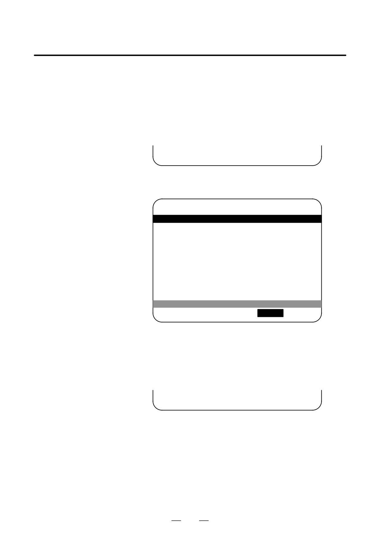
1. Press the [SYSTEM] function selection soft key. The following soft
keys are displayed together with the screen displayed when SYSTEM
was last selected. The currently active soft key is displayed in reverse
video.
[ PARAM ][ DGNOS ][
][SYSTEM][
]
2. Press the [SYSTEM] soft key again. The system configuration screen
appears. While this screen is displayed, the [SYSTEM] soft key is left
displayed in reverse video.
POWER MOTION MANAGER
SYSTEM CONFIGURATION
1.GROUP0 / β
SYSTEM
<SERIES/VERSION>
88A1 01
[ PARAM ][ DGNOS ][
][ SYSTEM ][
]
Sample screen: Series and edition of the servo unit β series system list
D Parameter screen
The parameters necessary for the functions of the slave must be specified
in advance.
1. Press the [SYSTEM] function selection soft key. The following soft
keys appear.
[ PARAM ][ DGNOS ][
][SYSTEM][
]
140
B-63525EN/02
1. DISPLAY AND OPERATION
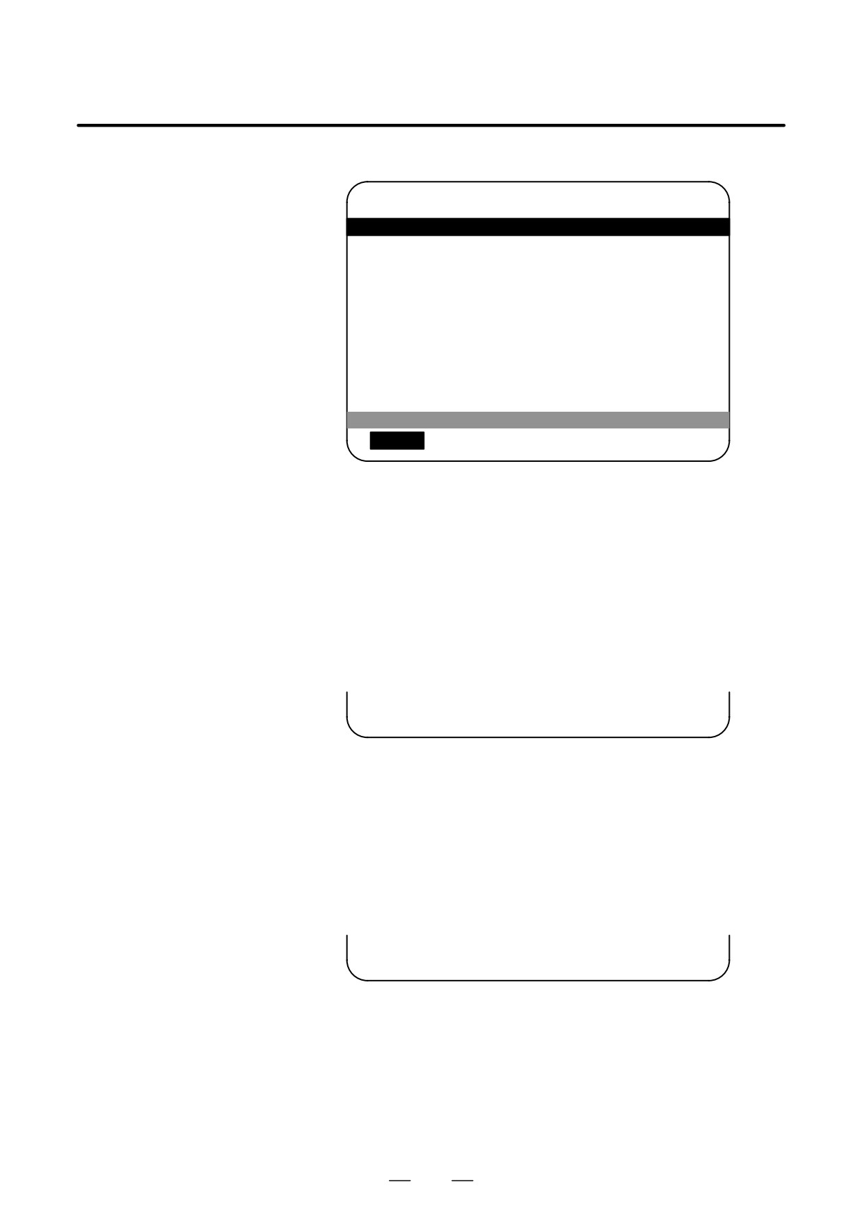
2. Press the [PARAM] soft key. The parameter screen appears.
POWER MOTION MANAGER
PARAMETER
1.GROUP0 / β
0000
00001000
0010
11110000
0001
00010101
0011
01010000
0002
11111011
0012
00000000
0003
00000000
0013
00000000
0004
00000000
0014
10110001
0005
10100001
0015
00000000
0006
00000000
0016
00000000
0007
10000000
0017
10000010
0008
00000000
0018
00000000
0009
00000000
0019
00000000
[
PARAM ][ DGNOS ][
][ SYSTEM ][
]
The screen displays just the bit and decimal data. For details of the
parameters, refer to the connection manual of the corresponding Power
Motion unit.
D Searching for a parameter
A search can be made for the parameter to be displayed.
1. Select the active slave.
2. Press the [(OPRT)] soft key. The following soft keys appear.
[ NO.SRC ][
][
][
][ INPUT ]
3. Enter a desired number in the key-in field by using MDI numeric keys.
Then, press the [NO.SRC] soft key. The search starts.
D Setting a parameter
A parameter of a slave Power Motion unit can be directly set from the
CNC.
1. Select the active slave.
2. Press the [(OPRT)] soft key. The following soft keys appear:
[ NO.SRC ][
][
][
][ INPUT ]
3. Move the cursor to the parameter to be set.
4. Enter desired data in the key-in buffer by using MDI numeric keys.
Then, press the [INPUT] soft key. Alternatively, press the MDI
INPUT key.
141
1. DISPLAY AND OPERATION
B-63525EN/02
D Diagnosis screen
This screen shows the current status of the slave.
1. Press the [SYSTEM] function selection soft key. The following soft
keys appear:
[ PARAM ][ DGNOS ][
][SYSTEM][
]
2. Press the [DGNOS] soft key. The diagnosis screen appears. The
displayed data is basically the same as the data displayed on the
parameter screen.
For details of the diagnosis information, refer to the connection
manual of the corresponding Power Motion unit.
D Current position display
The screen shows the current position on the workpiece coordinate
system or machine coordinate system.
1. Press the [POS] function selection soft key. The following soft keys
appear:
[ WORK
][
][MACHIN][
][
]
2. To see the absolute coordinate screen, press the [WORK] soft key. To
see the machine coordinate screen, press the [MACHIN] soft key.
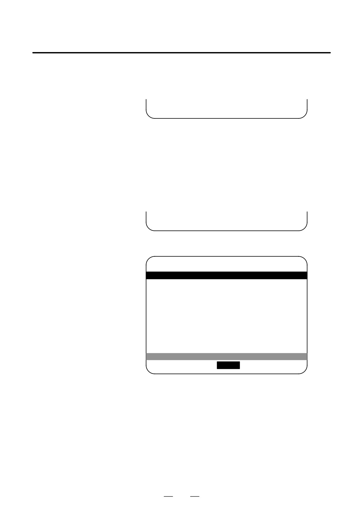
POWER MOTION MANAGER
ACTUAL POSITION (MACHINE)
1.GROUP0 / β
1
1267900
F
3500
[ WORK
][
][ MACHIN ][
][
]
1: Coordinate F: Actual speed
142
B-63525EN/02
1. DISPLAY AND OPERATION
D Alarm screen
If an alarm is issued during operation, the group number of the slave
causing the alarm is indicated at the right end of the message field on the
screen. Check the details on the alarm screen. For example, (13) means
that the first and third power motion units are in the alarm state.
1. Press the [MSG] function selection soft key. Just the error code is
displayed on the screen.
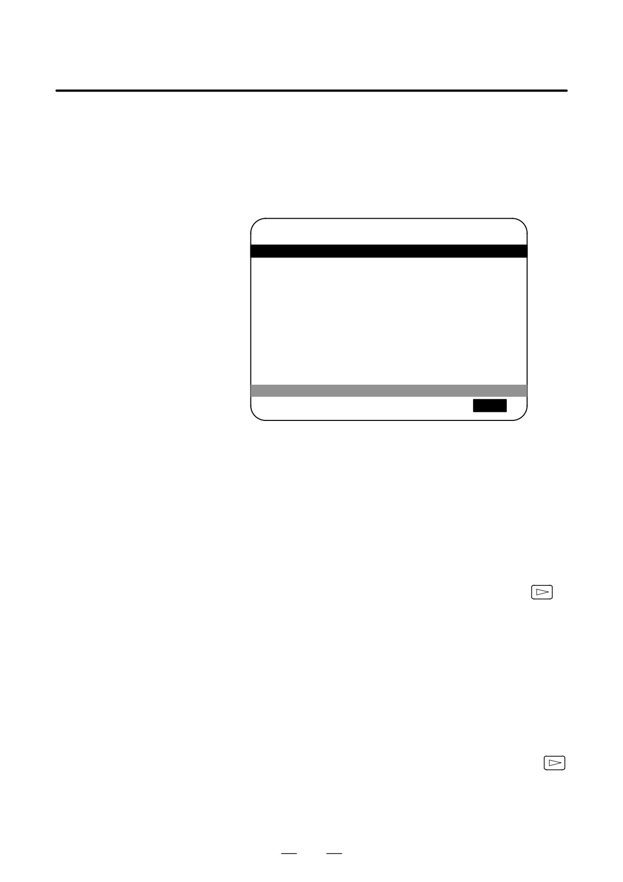
POWER MOTION MANAGER
ALARM
1.GROUP0 / β
442
210
232
[ POS
][
][
][SYSTEM ][
MSG
]
Up to forty codes can be displayed on the screen.
For details of the alarm, refer to the connection manual of the
corresponding Power Motion unit.
D Operating the active
The active slave is subjected to the ZOOM function, which will be
slave
described later, and parameter overwrite. The title of the active slave is
displayed in a color different from the display color of the other slave
titles.
The active slave can be selected by pressing the [±NEXT] or [°BACK]
soft key, which is displayed after the continuous menu key
is
pressed several times.
[±NEXT]: Displays the screen of the Power Motion unit connected after
the currently active slave. The equipment other than the
Power Motion unit is ignored.
[°BACK]: Displays the screen of the Power Motion unit connected
before the currently active slave.
D Single-slave display/
Whether the screen displays the data of just a single unit or of four units
Four-slave display
in four segments is specified in the SLV bit (bit 0 of parameter 960).
To switch the four-slave display to the single-slave display, press the
[ZOOM] soft key, which is displayed after the continuous menu key
is pressed several times. The single-slave display shows the data of the
active slave. To switch the single-slave display to the four-slave display
showing the data of four slaves including the active slave, press the
[ZOOM] key.
143
1. DISPLAY AND OPERATION
B-63525EN/02
When five or more slaves are connected, the four-slave display has two
or more pages. To see the slave data that is not displayed on the current
page, press soft key [±NEXT].
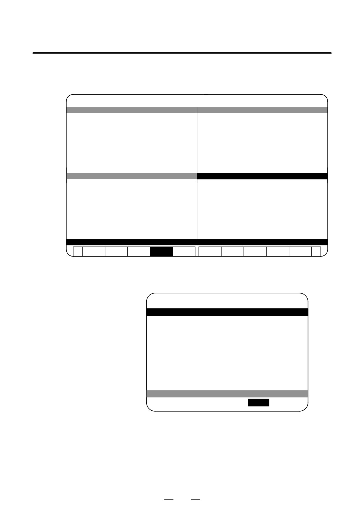
POWER MOTION MANAGER/ SYSTEM CONFIGURATION
O12345678 N12345
1.GROUP0 / β
O12345678 N12345
2.GROUP1 / β
SYSTEM
****##
SYSTEM
88A101
3.GROUP2 / β
4.GROUP3 / β
SYSTEM
88A101
SYSTEM
****##
SERVO
****##
PARAM
DGNOS
SYSTEM
(OPRT)
The figure above shows a sample four-slave display screen on a display
unit with twelve soft keys. A unit with seven soft keys can also display
the four-slave display screen.
POWER MOTION MANAGER
O12345678 N12345
SYSTEM CONFIGURATION
1.GROUP0 / β
SYSTEM <SERIES/VERSION>
88A101
[ POS
][ DGNOS ][
][ SYSTEM
][ MSG
]
The figure above shows a sample single-slave display screen on a display
unit with seven soft keys. A unit with twelve soft keys can also display
the single-slave display screen.
144
B-63525EN/02
1. DISPLAY AND OPERATION
D Guidance message
While the following soft keys are being displayed, a guidance message
is displayed in the message field.
[ POS
][
][
][SYSTEM][ MSG
]
[ WORK
][
][MACHIN ][
][
]
[ PARAM ][ DGNOS ][
][SYSTEM][(OPRT) ]
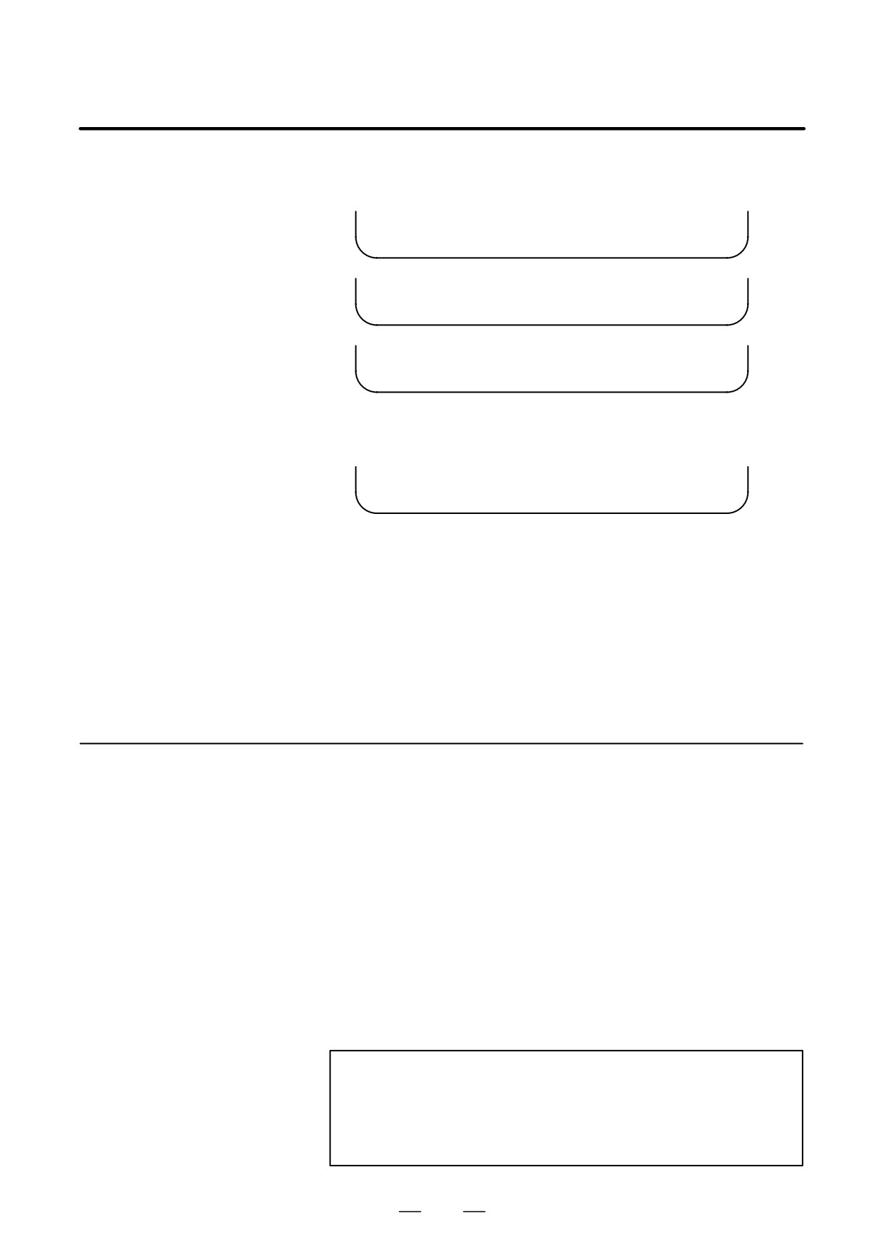
When the soft keys are displayed as shown above, “SELECT ACTIVE
SLAVE [>]” is displayed.
[ ±NEXT ][ °BACK ][ ZOOM
][
][
]
When the soft keys are displayed as shown above, “SELECT ACTIVE
SLAVE [↓] [↑]” is displayed.
D Key-in field
When the [(OPRT)] soft key is pressed, the message line may turn into a
key-in field as required. The numeric data input by using MDI keys is
displayed after the prompt (>).
On the parameter and diagnosis screens, the key-in field appears when
just a numeric value is input. The soft key [(OPRT)] need not be pressed.
1.18.3
Parameter Input/Output
D Saving parameters
Parameters can be saved in CNC memory or a memory card as a data file
of program format. Specify the first digit of the registration program
number in parameter 8760. Programs with predetermined numbers are
created for individual slaves. When the parameters are saved in CNC
memory, a program having the specified program number is created.
When the parameters are saved in a memory card, a file is created, to
which the file name consists of the specified program number and an
extension PMM.
Example: When parameter 8760 is set to 8000
The program number for group n is 8000 + n*10.
The group number n is indicated in the title area of each slave.
CAUTION
In case that the parameters are saved in a memory card, If
the specified program number already exists on memory
card, the corresponding program is overwritten with new
data.
145
1. DISPLAY AND OPERATION
B-63525EN/02
Specify a desired input device in the MD1 and MD2 bits (bits 1 and 2 of
parameter 960). Connect a memory card. Alternatively, check the free
area of CNC memory. Then, follow the steps given below:
1. Select the active slave.
2. Press the [(OPRT)] soft key. The following soft keys appear:
[ NO.SRC ][
][
][
][ INPUT ]
3. Press the continuous menu key
. The following soft keys appear:
[
][ READ
][ PUNCH
][
][
]
4. Press the [READ] soft key. The following soft keys appear:
[
][
][
][CANCEL ][ EXEC
]
5. Press the [EXEC] soft key.
During input, “INPUT” blinks in the message field.
D Writing parameters
The data file of parameters saved in CNC memory or a memory card as
a program is written into the slave determined by the program number.
The program number and memory device are determined as described in
“Saving parameters.”
1. Select the active slave.
2. Press the [(OPRT)] soft key. The following soft keys appear:
[ NO.SRC ][
][
][
][ INPUT ]
3. Press the next-menu key. The following soft keys appear:
[
][ READ
][ PUNCH
][
][
]
4. Press the [PUNCH] soft key. The following soft keys appear:
[
][
][
][CANCEL ][ EXEC
]
5. Press the [EXEC] soft key.
During output, “INPUT” blinks in the message field.
The screen cannot be changed to another screen during parameter
input/output.
When the RESET key is pressed, or when an alarm status is detected in
communication, the input/output stops.
146
B-63525EN/02
1. DISPLAY AND OPERATION
1.18.4
Notes
D Connecting an I/O Link
When the Power Motion series is used as a slave of an I/O Link, the CNC
assigns I/O addresses. The salve data is input and output in units of 16
bytes. Therefore, 128 input/output points are necessary. Up to eight
slaves can be connected.
The module name is OC021 (16-byte input) or OC020 (16-byte output).
BASE is always 0, and SLOT is always 1.
D Ignoring the power
After the data necessary for each slave connected is set and checked, the
motion manager function
communication of the power motion manager (PMM) can be stopped to
send a command from the CNC ladder to the slave.
When the PMN bit (bit 3 of parameter 960) is set to 1, all communication
between CNC and the slave via the I/O Link is open to the ladder.
While the bit is held 1, the screen shows just the title, function name, and
other items that are independent of the communication. The following
message appears to indicate that communication has stopped.
COMMUNICATION PROHIBITED BY P960#3
D Data input/output by I/O
When the power motion manager is used, the function for data
Link
input/output by I/O Link cannot be used.
D Alarm
(1) CNC
When a CNC alarm status is detected, the screen is automatically
switched to the CNC alarm screen. Check the details of the alarm. If
necessary, display and select the power motion manager screen again
SYSTEM
by pressing function key
(2) Slave
A guidance message is usually displayed in the message field. If a
slave alarm is detected, the corresponding slave group number is
displayed at the right end.
Display the alarm screen to check the details.
D Data protection key
When the data protection key of the CNC is turned on, parameters cannot
be input to CNC memory.
147

1. DISPLAY AND OPERATION
B-63525EN/02
Using the periodic maintenance screens makes it easy to manage
1.19
consumables (such as LCD unit backlight and backup battery) that are to
PERIODIC
be replaced periodically.
MAINTENANCE
Setting the name and service life of consumables, and the countdown
SCREENS
method to be used for them enables counting of the remaining service time
according to the specified countdown method and displaying of the result.
1.19.1
Overview
D Screen configuration
The following periodic maintenance screens are available:
(1) Status screen: Displays item names, remaining service time,
countdown status, and lets you specify item names.
(2) Setting screen: Lets you specify service life, remaining service time,
and count type (countdown method).
(3) Machine system menu screen: Enables registering the names of
consumables used in the machine.
(4) NC system menu screen: Displays the names of registered
consumables used in the NC.
D Procedure
To use this function, follow the steps below:
(1) Select a number for registration (using the cursor key on the status
screen).
(2) Specify an item name.
The following two methods are available.
- Selecting a name from a menu screen (machine or NC system menu
screen).
- Entering a name to the status screen directly from the MDI.
Using the machine system menu screen requires that item names be
registered previously.
(3) Specify the service life, remaining service time, and count type for a
target item.
Once they are specified, the remaining service time can be checked
on the status screen.
1.19.2
SYSTEM
1
Press the
function key.
Screen Display and
Setting
2
Press the
continuous menu key several times. Soft key
[MAINTE] appears.
3
Press soft key [MAINTE]. A periodic maintenance screen appears.
There are two periodic maintenance screens, status and setting screens.
Either screen can be selected using soft key [CHANGE].
148
B-63525EN/02
1. DISPLAY AND OPERATION
1.19.3
Up to 10 consumable items can be registered for management. Their
remaining service time and count status are displayed on the status screen.
Status Screen Display
and Setting
PERIODICAL MAINTENANCE
O0001 N12345
(STATUS)
ITEM NAME
REMAIN
*01
BATTERY FOR CONTROLLER
0H
@02
BATTERY FOR PULSECODER
5000H
03
FAN MOTOR
10000H
@04
LCD BACK LIGHT
720H
05
06
07
08
09
10
>_
EDIT *** ***** *** ****
19:27:05
[
][ MAINTE ][
][
][ (OPRT) ]
[ CHANGE ][ ENTRY ][ CLEAR ][ +INPUT ][ INPUT ]
[
][
][
][ CAN
][ EXEC
]
(1) Item name
The name of an item to be subjected to periodic maintenance is
specified under “Item name.”
Two methods can be used to specify item names. The first method uses
the menu screen, and the second, the MDI keypad.
(1) Method of using the menu screen
1
Place the cursor on the target item name, and press soft key
[ENTRY]. A menu screen appears. The menu screen is either
the machine or NC system menu screen.
2
Press soft key [MACHIN] or [NC]. A machine system menu
appears. It holds the names of consumables typical to the
machine system or NC system.
3
Place the cursor on a registered item name, and press soft key
[SELECT], then soft key [EXEC]. The status screen appears
again, enabling the selected item to be set up.
4
Press soft key [CAN]. The previous soft key displays appear
again.
5
Press soft key [MAINTE]. The status screen appears again.
Using the machine system menu screen requires that item names
be registered on the screen previously.
This can be done using two methods, (a) and (b).
(a) Program-based registration
Executing a program in the following format enables item
names to be registered on the machine system menu screen.
149
1. DISPLAY AND OPERATION
B-63525EN/02
Format
G10 L61 Px [n]
x… Registration number
n… Item name
[Alphanumeric characters*two-byte
characters*alphanumeric characters]
(b) MDI keypad-based registration
An item name can be registered on the machine system menu
screen by first entering it in the following format, then pressing
soft key [INPUT] (or
INPUT
function key).
Pressing soft key [+INPUT] adds the item name to the list of
previously registered item names.
Format
Alphanumeric characters*two-byte characters*alphanumeric characters
The two-byte characters shall comply with the FANUC code.
(See Section 1.19.6.)
When entering a two-byte character, sandwich it with an “*”
pair.
The item name can consist of up to 24 alphanumeric characters
(if no two-byte character is included) or 12 two-byte characters
(if no alphanumeric character is included).
Example) To register “LCD backlight,” enter:
>LCD*110E10F410CC114010B610FE_
NOTE
1
“*” cannot be used in item names, because it is used as
control code.
“[”, “]”, “(“, or “)” also cannot be used in item
names.
2
When both alphanumeric and two-byte characters are
used in an item name to be registered, the warning
message “DATA IS OUT OF RANGE” may appear even if
the maximum allowable number of characters has not been
exceeded.
3
If a blank item name is selected from the machine system
screen, the warning message “EDIT REJECTED” appears.
If a blank item name is selected from the NC system screen,
a blank is set up.
150
B-63525EN/02
1. DISPLAY AND OPERATION
To erase the registered data for an item, place the cursor on the
target item name, and press soft key [CLEAR], then soft key
[EXEC].
[Machine system] menu screen
PERIODICAL MAINTENANCE
O0001 N12345
(MACHINE)
ITEM NAME
01
02
03
04
05
06
07
08
09
10
>_
EDIT *** ***** *** ****
19:27:05
[
][ STATUS ][ MACHIN ][ NC
][ (OPRT) ]
[ SELECT ][
][ CLEAR ][ +INPUT ][ INPUT ]
[
][
][
][ CAN
][ EXEC
]
[
][ READ
][ PUNCH ][
][
]
[
][
][
][ CAN
][ EXEC
]
151