FANUC Series 16i/160i/160is-MODEL B, Series 18i/180i/180is-MODEL B, Series 21i/210i/210is-MODEL B. MAINTENANCE MANAUL - page 5
1. DISPLAY AND OPERATION
B-63525EN/02
D Diagnostic data related
to simple synchronous
control
DGN
540
Difference in the position error between the master and slave axes in simple synchro-
nas control
DGN
541
Difference in the position error between the master and slave axes in simple synchro-
nas control
DGN 540 indicates the difference in the position error between the master
and slave axes when a single axis pair is subjected to simple synchronous
control. DGN 541 is used when two or more pairs are subjected to simple
synchronous control. The position error is indicated for the master axis.
DGN 540 and 541 indicate values in detection units. They are displayed
only with the M series.
D Diagnostic data related
to the dual position
feedback function
DGN
550
Closed loop error
[Data type]
2-word axis
[Unit of data]
Detection units
[Valid data range]
-99999999 to +99999999
DGN
551
Semi-closed loop error
[Data type]
2-word axis
[Unit of data]
Detection units
[Valid data range]
-99999999 to +99999999
DGN
552
Error between semi-closed and closed loops
[Data type]
word axis
[Unit of data]
Detection units
[Valid data range]
-32768 to +32767
DGN
553
Amount of dual position compensation
[Data type]
2-word axis
[Unit of data]
Detection units
[Valid data range]
-99999999 to +99999999
92
B-63525EN/02
1. DISPLAY AND OPERATION
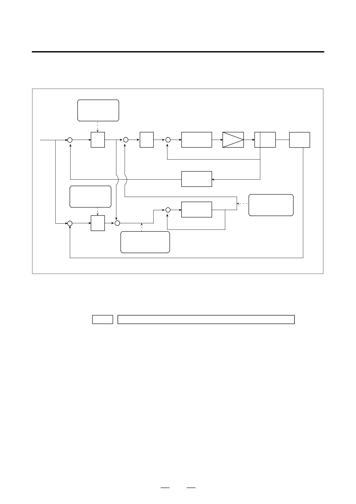
The data items displayed on the diagnosis screen are obtained at the
following positions:
Semi-closed loop
error (No. 551)
Motor
Command
+
+
+
Speed
S
Kp
Machine
control
-
+
-
Servo amplifier
Ps
Conversion
coefficients
(Parameters No. 2078 and 2079)
Closed loop error
(No. 550)
Amount of dual
+
position compensa-
Time
tion (No. 553)
constant
+
-
+
(Parameter No. 2080)
S
-
+
Error between semi-
Pf
closed and closed
loops (No. 552)
D Status after execution of
manual tool
compensation (for the T
series only)
DGN
560
Status after execution of manual tool compensation
0 : Manual tool compensation ended normally.
1 : The data of the T code command is out of the allowable range.
2 : The offset value is out of the allowable range.
3 : The offset number is out of the allowable range.
4 : The CNC is running automatically or moving the axes.
5 : The CNC is in tool tip radius compensation mode.
6 : The CNC is not in JOG or HNDL (INCR) mode.
7 : The setting of a CNC parameter is invalid.
93
1. DISPLAY AND OPERATION
B-63525EN/02
D FSSB2 status
#7
#6
#5
#4
#3
#2
#1
#0
DGN
620
CFE
ERR
ERP
OPN
RDY
OPP
CLS
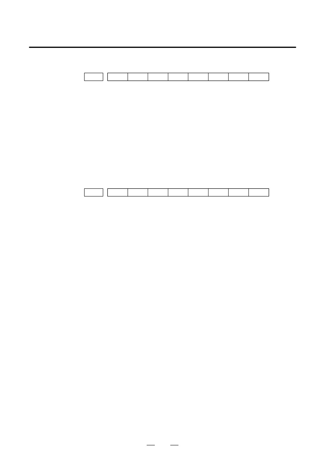
Indicates the internal status of the FSSBC2.
#0(CLS): Closed.
#1(OPP): Running OPEN protocol.
#2(RDY): Open and ready.
#3(OPN): Open.
#4(ERP): Running ERROR protocol.
#7(CFE): Encountered configuration error.
(The actual slave type does not match the one specified in the conversion
table.)
#7
#6
#5
#4
#3
#2
#1
#0
DGN
621
XE3
XE2
XE1
XE0
ER3
ER2
ER1
ER0
Indicates the cause of an FSSBC2 error.
#0(ER0): INFORMED ERROR
#1(ER1):
(RESERVE)
#2(ER2): Master port disconnection
#3(ER3): External EMG input
Indicates the cause of an FSSBC2 error resulting from a request from a slave.
#4(XE0):
(RESERVE)
#5(XE1): Slave port disconnection
#6(XE2): Master port disconnection
#7(XE3): External EMG input
94
B-63525EN/02
1. DISPLAY AND OPERATION
#7
#6
#5
#4
#3
#2
#1
#0
DGN
630
EXT
DUA
ST1
ST0
#7
#6
#5
#4
#3
#2
#1
#0
DGN
632
EXT
DUA
ST1
ST0
to
#7
#6
#5
#4
#3
#2
#1
#0
DGN
648
EXT
DUA
ST1
ST0
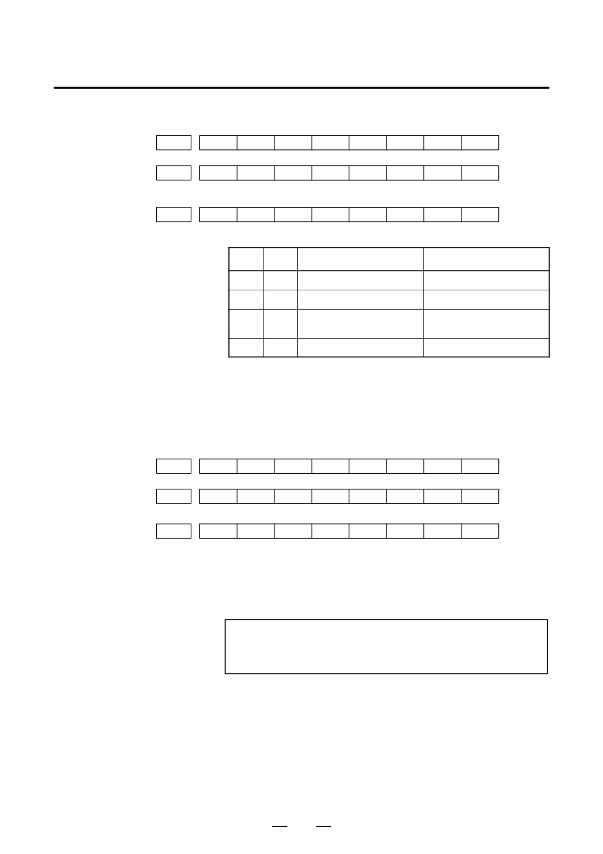
#0, #1(ST0, ST1):
Indicates the type code for an actually connected slave.
ST1
ST0
Type
Address
0
0
A
Servo amplifier
0
1
(B: RESERVE)
(Currently nonexistent)
1
0
C
Stand-alone type detector inter-
face unit
1
1
(RESERVE)
(Currently nonexistent)
#2(DUA):
0 : The slave of interest is not on the first axis of the two-axis amplifier.
1 : The slave of interest is on the first axis of the two-axis amplifier.
#3(EXT):
0 : The slave of interest does not exist.
1 : The slave of interest exists.
#7
#6
#5
#4
#3
#2
#1
#0
DGN
631
DMA
TP1
TP0
HA2
HA1
HA0
#7
#6
#5
#4
#3
#2
#1
#0
DGN
633
DMA
TP1
TP0
HA2
HA1
HA0
to
#7
#6
#5
#4
#3
#2
#1
#0
DGN
649
DMA
TP1
TP0
HA2
HA1
HA0
#0, #1, #2(HA0, HA1, HA2):
Indicates the host LSI address specified as a DMA destination.
#3, #4 (TP0, TP1):
Indicates the type code of a specified slave.
(See the above descriptions about ST0 and ST1.)
#5(DMA):
Indicates a value determining whether to allow DMA to occur.
NOTE
A combination of parameter Nos. 630 and 631 corresponds
to one FSSB2 slave unit. Up to ten slave units are available.
95
1. DISPLAY AND OPERATION
B-63525EN/02
Slave units and the associated diagnosis numbers
Slave unit 00
³
Diagnosis No. 630, No. 631
Slave unit 01
³
Diagnosis No. 632, No. 633
Slave unit 02
³
Diagnosis No. 634, No. 635
Slave unit 03
³
Diagnosis No. 636, No. 637
Slave unit 04
³
Diagnosis No. 638, No. 639
Slave unit 05
³
Diagnosis No. 640, No. 641
Slave unit 06
³
Diagnosis No. 642, No. 643
Slave unit 07
³
Diagnosis No. 644, No. 645
Slave unit 08
³
Diagnosis No. 646, No. 647
Slave unit 09
³
Diagnosis No. 648, No. 649
D State of high-speed HRV
current control
#7
#6
#5
#4
#3
#2
#1
#0
DGN
700
HOK
HON
[Data type]
Bit axis
The state of high-speed HRV current control is displayed.
HON:
The motor is controlled in the high-speed HRV current control mode.
HOK:
This bit is set to 1 when high-speed HRV current control is enabled.
High-speed HRV current control is enabled when the following
conditions are satisfied:
- Bit 0 (HR3) of parameter No. 2013 is set to 1.
- Servo software, servo modules, and servo amplifiers suitable for
high-speed HRV current control are used.
- When a separate detector interface unit is used, the separate detector
interface unit is suitable for high-speed HRV current control.
D Error and warning
statuses of the αi spindle
DGN
710
Error status of first spindle
DGN
711
Error status of second spindle
[Data type]
Word
DGN
712
Warning status of first spindle
DGN
713
Warning status of second spindle
[Data type]
Word
DGN
730
Error status of third spindle
DGN
731
Error status of fourth spindle
[Data type]
Word
96
B-63525EN/02
1. DISPLAY AND OPERATION
DGN
732
Warning status of third spindle
DGN
733
Warning status of fourth spindle
[Data type] Word
If an error (the yellow LED flashes and the error number appears) or
warning occurred in the αi spindle amplifier module (SPM), the number
is displayed on the diagnostic screen.
When there is no error or warning, ”0” is indicated.
NOTE
1
For spindles older than the αi spindle, this function is invalid.
2
When the system configuration of the spindle (even another
spindle) includes an additional spindle older than the αi
spindle, this function is invalid.
Refer to the FANUC SERVO MOTOR αi series Maintenance Manual
(B-65285EN) for errors on the αi spindle.
See Subsection 10.1.4, ”Warning Interface for the αi Spindle” in this
manual for warnings.
97
1. DISPLAY AND OPERATION
B-63525EN/02
1.9
CNC STATE DISPLAY
ACTUAL POSITION (ABSOLUTE)
O1000 N00010
X
217.940
Y
363.233
Z
0.000
PART COUNT
5
RUN TIME
0H15M CYCLE TIME
0H
0M38S
ACT.F
3000MM/M
S
0
T0000
MEM
STRT MTN
***
09:06:35
[ ABS ]
[ REL ]
[ ALL ]
[ HNDL ]
[ OPRT ]
· Indicates the current status of the CNC.
· Display example and explanation
MEM
STRT MTN
***
09:06:35
(1)
(2)
(3)
(4)
(7)
(8)
(5)
(1) Mode selection status
MEM: Automatic operation (memory operation)
MDI: Manual data input/MDI operation
EDIT: Program editing
RMT: Remote operation
JOG: Jog feed
REF: Reference position return
INC: Incremental feed mode = step feed (if no manual pulse
generator is available)
HND: Manual handle feed mode
TJOG: Teaching in jog feed mode
THND:Teaching in handle feed mode
(2) Automatic operation status
STRT: Automatic operation has started (and program execution is
under way).
HOLD:Automatic operation has been suspended (execution of a
block has been discontinued, and automatic operation has
stopped).
STOP: Automatic operation has stopped (a block has been finished,
and automatic operation has stopped).
MSTR: The tool is returning or being repositioned when the tool
retract and return function is executed.
****: Other status (when the power is switched on, or automatic
operation has ended)
98
B-63525EN/02
1. DISPLAY AND OPERATION
(3) Automatic operation status
MTN: Program-specified axis movement is under way.
DWL: Program-specified dwell command (G04) is being executed.
***: Other status
(4) Auxiliary function status
FIN: The completion signal FIN for an auxiliary function is being
awaited.
***: Other status
(5) Emergency stop and reset status (displayed at the location of items
mentioned in (3) and (4))
--EMG--
: Emergency stop status
–RESET-: CNC reset status (The state in which the reset signal or
the MDI RESET key remains active.)
(6) Alarm status
ALM : An alarm condition has been detected.
BAT
: The lithium battery (CNC back-up battery) voltage is low
(the battery is to be replaced).
Blank: Other status
(7) Clock display: Hour:minute:second
(8) Program editing/running status
Input:
Data is being input.
Output:
Data is being output.
SRCH:
A data search is under way.
EDIT:
Editing such as insertion or modification is under way.
LSK:
Label skip enabled at data input (until valid information
is read).
PTRR:
Retract or return/re-positioning is under way when the
tool retrack and return function is used.
HPCC:
High-precision contour control mode.
AICC:
AI contour control mode.
AI NANO: AI nano contour control mode
AI HPCC: AI high-precision contour control mode
NANO HP: AI nano high-precision contour control mode
AIAPC: AI advanced preview control mode
RVRS:
Reversing based on the retrace function.
RTRY:
Re-advancing based on the retrace function.
RVED:
Reversing based on the retrace function has ended.
Blank:
Editing is not under way.
99
1. DISPLAY AND OPERATION
B-63525EN/02
Tuning becomes easier by graphically displaying servo error amount and
1.10
torque command, etc. (Graphic option is required).
WAVEFORM
The following two types of waveform diagnosis functions are supported:
DIAGNOSTIC
FUNCTION
(1) One-shot type
The one-shot type waveform diagnosis function can graphically
display, as a waveform, any variation in those data items listed below.
The start of data sampling can be triggered by the rising or falling edge
of a machine signal. This function facilitates the adjustment of the
servo and spindle motors.
a. Error, pulse distribution amount, torque, speed, current, and
thermal simulation data for the servo motor of each axis
b. Composite speed for the first, second, and third axes
c. Spindle motor speed and load meter value
d. On/off state of a machine signal specified with a signal address
(2) Storage type
The storage type waveform diagnosis function enables the storing
of any variation in the data items listed below and, if a servo alarm
occurs, the graphical display (as a waveform) of the stored data. The
end of data sampling can be triggered by the rising or falling edge
of a machine signal. This function facilitates the estimation of
erroneous locations. Stored data can be output via the reader/punch
interface.
a. Error, pulse distribution amount, torque, speed, current, and
thermal simulation data for the servo motor for each axis
NOTE
1
To output stored waveform data, the optional reader/punch
interface must have been installed.
2
The waveform diagnosis function is enabled when bit 0
(SGD) of parameter No. 3112 is set to 1. Note, however, that
a graphics card is necessary to display waveforms.
1.10.1
Setting Parameters
#7
#6
#5
#4
#3
#2
#1
#0
DGN
3112
SGD
#0(SGD)
0 : Do not display servo waveform (usual graphic display).
1 : Displays servo waveform (usual graphic display function cannot be
used).
DGN
3120
Time between servo alarm and sampling stop (storage type)
[Data type] Word
[Unit of data] ms
[Valid data range] 1 to 32760
100
B-63525EN/02
1. DISPLAY AND OPERATION
DGN
3121
Selection of data of waveform diagnosis storage type
[Data type] Byte
The sixth-type sampling data of storage type of the waveform diagnosis
function is:
0 : Thermal simulation data
1 : Spindle load meter data of the first spindle
1.10.2
SYSTEM
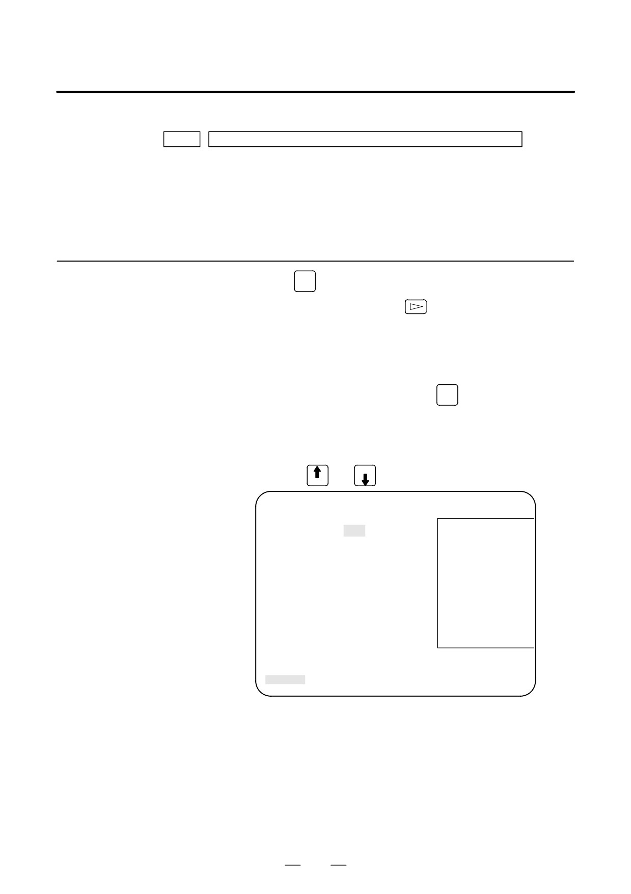
1.Press the
key to display a system screen such as aparameter.
Waveform Diagnostic
2. Press the continuous menu key
several times, and the soft key
Parameter Screen
[W.DGNS] is displayed.
3. Press
[W.DGNS], then the parameter screen for the waveform
diagnosis is displayed.
Set the necessary data items. Position the cursor to the item to be set,
enter the corresponding data, then press
INPUT
. Data items for which
***** is displayed cannot be set. To assist in data setting, the frame on
the right side of the screen displays help information for that data to which
the cursor is positioned. Help information which cannot fit into a single
frame is split into several pages, which the user can scroll through using
PAGE
the page keys
and
PAGE
WAVE DIAGNOSE (PARAMETER)
O1234 N12345
GRP CONDITION 100
GRP CONDITION
(ONE-S TYPE)
SAMPLING TIME *****MS
0:START
TRIGGER *******
1:START&TRG
↑
2:START&TRG
↓
(MEMORY TYPE)
(CH-1)
(CH-2)
100: DATA OF
DATA NO.
11
22
MEMORY
UNIT
1000
10
1/3
SIGNAL
*******
*******
>
S
0
T0000
EDIT **** *** ***
08:20:52
[W.PRM]
[W.GRPH]
[ W.MEM ]
[
]
[
]
D Waveform diagnosis
(1) Display start condition
parameters (one-shot
0 : Starts data sampling upon the
[START] key being pressed,
type)
samples data for the specified period, then draws a waveform.
1 : Starts data sampling upon the detection of the first rising edge of
the trigger signal after the [START] key is pressed, samples data
for the specified period, then draws a waveform.
2 : Starts data sampling upon the detection of the first falling edge of
the trigger signal after the [START] key is pressed, samples data
for the specified period, then draws a waveform.
101
1. DISPLAY AND OPERATION
B-63525EN/02
(2) Sampling period: Set the period during which data will be sampled.
Valid data range: 10 to 32760
Units: ms
(3) Trigger: Set the PMC address and bit for the signal used to trigger the
start of data sampling, when 1 or 2 is set for the start condition.
Example) G0007.2: ST signal
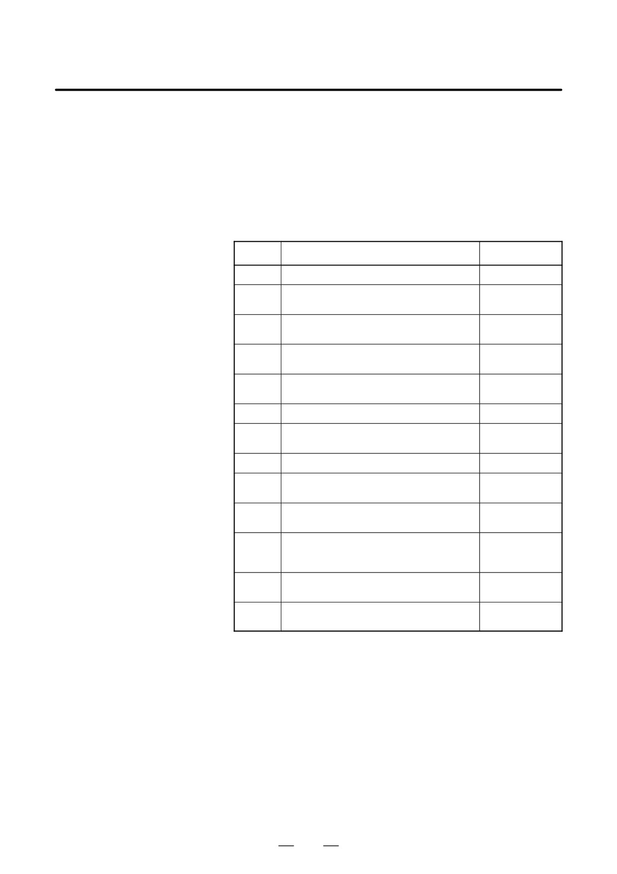
(4) Data number: The table below lists the numbers of the data items for
which a waveform can be displayed (n = 1 to 8).
Data No.
Description
Units
00
Does not display a waveform.
-
0n
Servo error (8 ms) for the n-th axis (positional devi-
Pulses
ation)
(detection units)
1n
Pulse distribution for the n-th axis
Pulses
(move command)
(input increments)
2n
Torque for the n-th axis (actual current)
% (relative to maxi-
mum current)
3n
Servo error (2 ms) for the n-th axis (positional devi-
Pulses
ation)
(detection units)
5n
Actual speed for the n-th axis
min-1
6n
Command current for the n-th axis
% (relative to maxi-
mum current)
7n
Thermal simulation data for the n-th axis
% (OVC alarm ratio)
90
Composite speed for the first, second, and third axes
Pulses
(input increments)
99
On/off state of a machine signal specified with a sig-
None
nal address
10n
Actual spindle speed for the n-th axis
% (relative to maxi-
mum rotation
speed)
11n
Load meter for the n-th spindle
% (relative to maxi-
mum output)
161
Difference in position error calculated on the spindle
Pulses (detection
basis
unit)
(5) Data units: Weight of data when 1 is specified. The data units are
automatically specified for each data item and need not be set unless
the units must be changed for some reason.
[Valid data range] 1 to 1000
[Unit] 0.001
(6) Signal address: PMC address and bit number. Set in the same way as
that for trigger, when the data number is 99.
102
B-63525EN/02
1. DISPLAY AND OPERATION
D Waveform diagnosis
(1) Display start condition
parameters (storage
100 : Draws a waveform for the stored data.
type)
(2) Sampling period: Invalid
(3) Trigger: Invalid
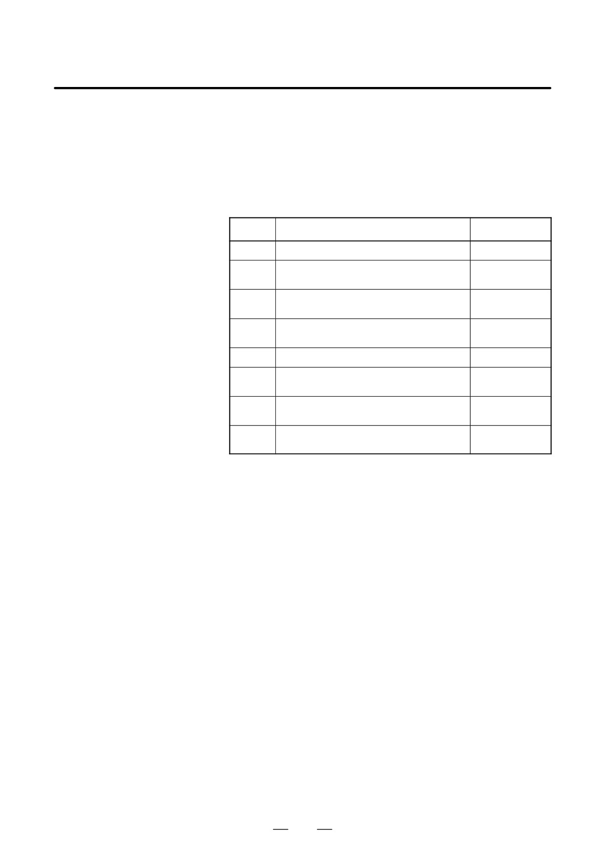
(4) Data number: The table below lists the numbers of the data items for
which a waveform can be displayed (n = 1 to 8). Numbers for which
no data is stored cannot be specified.
Data No.
Description
Units
00
Does not display a waveform.
-
0n
Servo error (8 ms) for the n-th axis (positional devi-
Pulses
ation)
(detection units)
1n
Pulse distribution for the n-th axis (move command)
Pulses
(input increments)
2n
Torque for the n-th axis (actual current)
% (relative to maxi-
mum current)
5n
Actual speed for the n-th axis
min-1
6n
Command current for the n-th axis
% (relative to maxi-
mum current)
7n
Thermal simulation data for the n-th axis
% (OVC alarm ratio)
(when the parameter No.3121 is set to 0.)
111
Load meter for the n-th spindle
% (relative to maxi-
(when the parameter No.3121 is set to 1.)
mum output)
(5) Data units: Weight of data when 1 is specified. The data units are
automatically specified for each data item and need not be set unless
the units must be changed for some reason.
[Valid data range] 1 to 1000
[Unit] 0.001
(6) Signal address: Invalid
103
1. DISPLAY AND OPERATION
B-63525EN/02
1.10.3
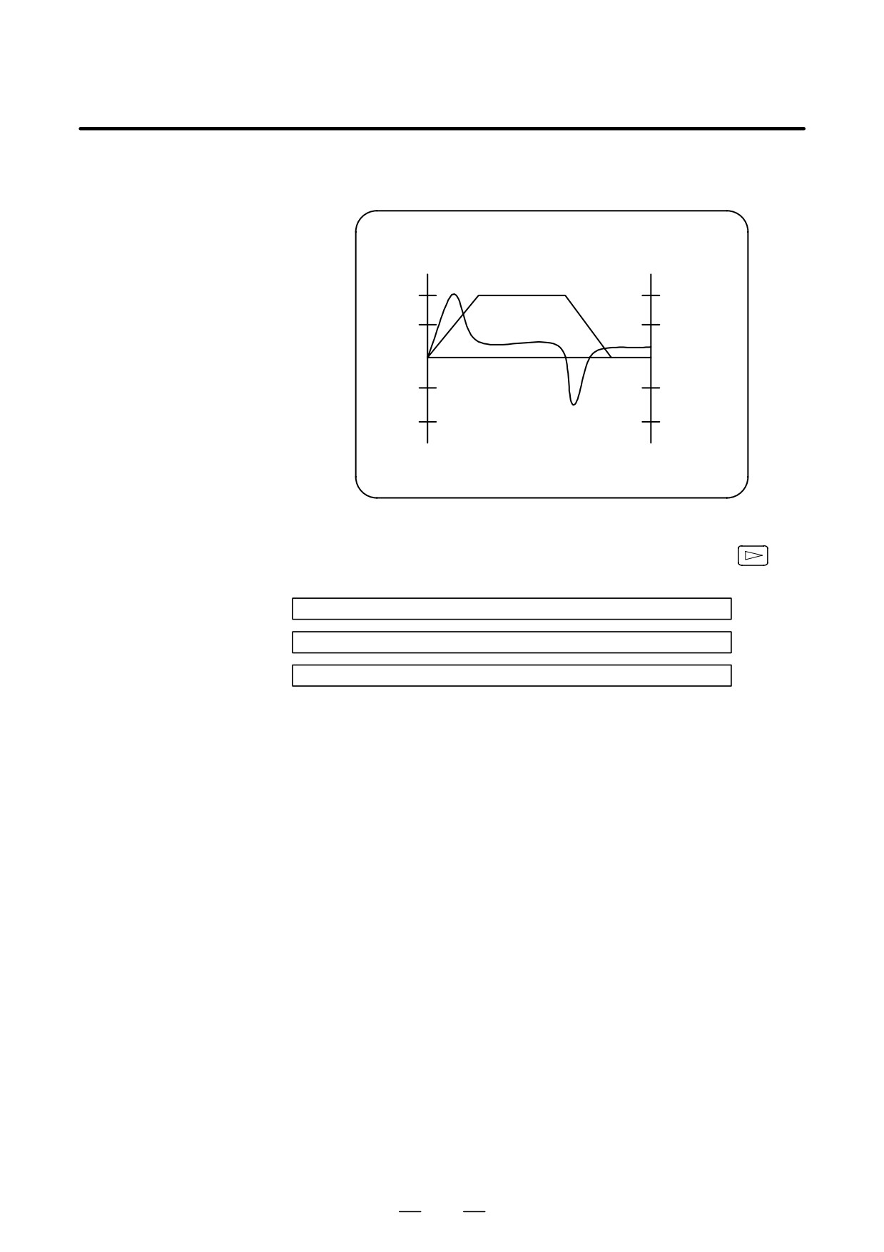
1. Press soft key [W.GRPH], then graph of waveform diagnosis is
displayed.
Graphic of Wave
Diagnosis data
WAVE DIAGNOSE (GRAPHIC)
CH1
CH2
1.0
1.0
0.5
0.5
0
0
-0.
-0.
5
5
-1.
-1.
0
0
[START] [TIME³] [²TIME] [H-DOBL] [H-HALF]
2. Press soft key [(OPRT)], then the following soft keys are displayed.
The following three sets of soft keys are displayed by the
key.
[START] [TIME³] [²TIME] [H-DOBL] [H-DOBL]
[START] [CH-1°] [CH-1±] [V-DOBL] [V-HALF]
[START] [CH-2°] [CH-2±] [V-DOBL] [V-HALF]
1)
[START ]
: Starts Graphic data
2)
[TIME→]
: Shift the waveform of channel 1 and 2 rightward
3)
[←TIME]
: Shift the waveform of channel and 2 leftward
4)
[H-DOBL] : Double the time scale of the waveform of channel 1
and 2
5)
[H-HALF] : Half the time scale of the waveform of channel 1 and 2
6)
[H-DOBL] : Double the height of waveform of channel 1 and 2
7)
[V-HALF]
: Half the height of waveform of channel 1 and 2
8)
[CH-1↑]
: Shift the zero point of channel 1 upward
9)
[CH-1↓]
: Shift the zero point of channel 1 downward
10) [CH-2↑]
: Shift the zero point of channel 2 upward
11) [CH-2↓]
: Shift the zero point of channel 2 downward
D Drawing a waveform for
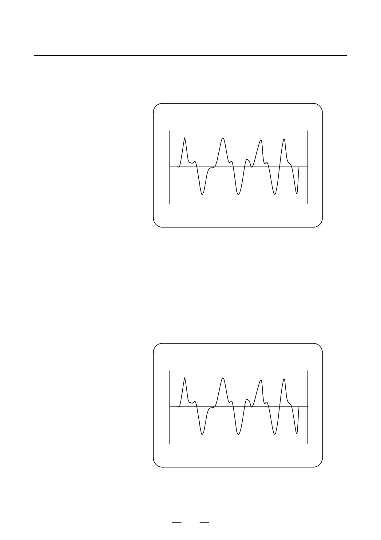
The one-shot type waveform diagnosis function draws a waveform for a
one-shot type waveform
specified data item in real time as the data is sampled. The sampled data,
diagnosis
however, is not stored and thus cannot be output later.
To sample data for one-shot type waveform diagnosis, press the
[START] key on the WAVE DIAGNOS. (GRAPHIC) screen. Then, data
is sampled when the specified start condition is satisfied. Data sampling
continues for the specified period.
104
B-63525EN/02
1. DISPLAY AND OPERATION
Pressing the [SATART] soft key starts data sampling. While sampling
is being performed, SAMPLING blinks at the top of the screen. Once data
sampling has been completed, a waveform is automatically displayed.
WAVE DIAGNOS. (GRAPHIC)
O1234 N12345
CH1
CH2
EDIT **** ******
[START] [TIME³] [²TIME] [H-DOBL] [H-HALF]
D Drawing a waveform for
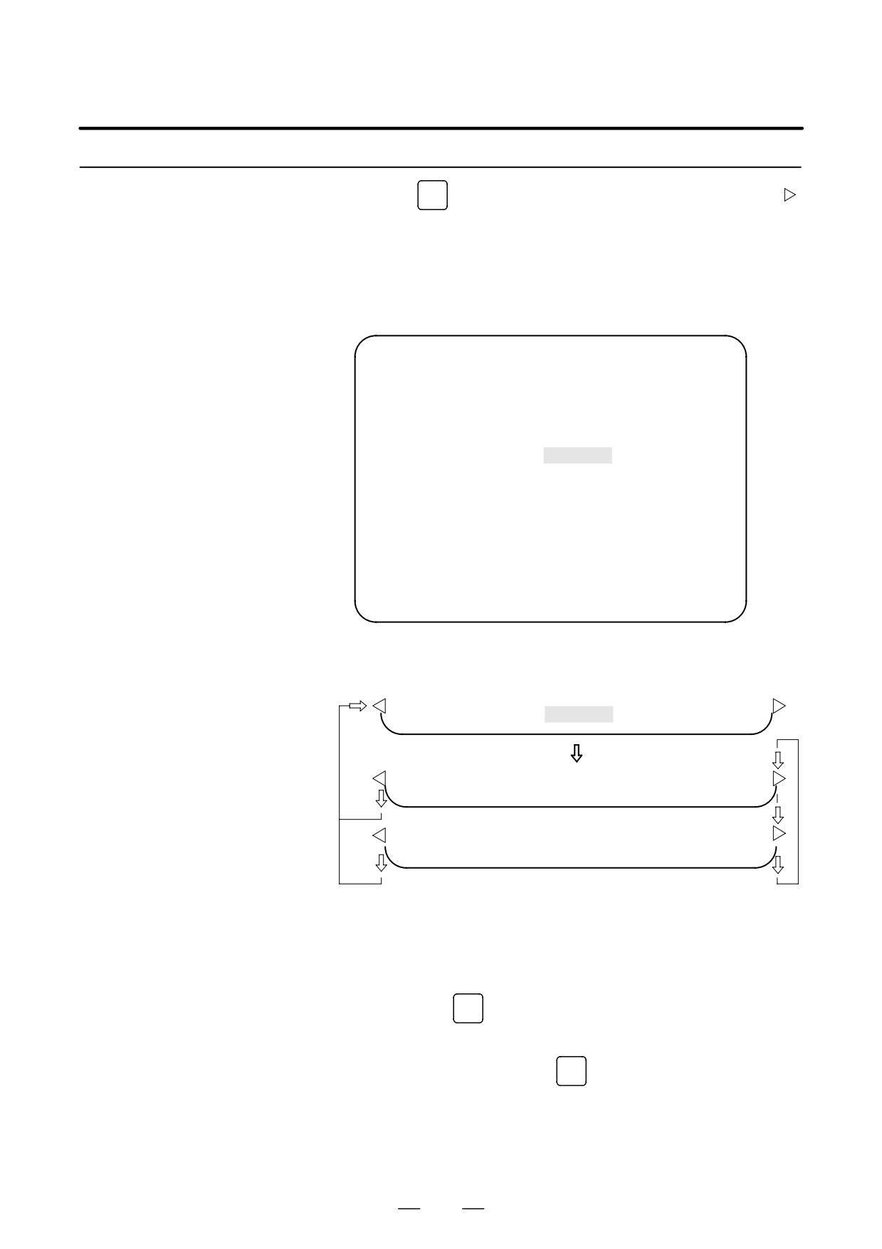
To use storage type waveform diagnosis, set 100 for the display start
storage type waveform
condition. The maximum data width for storage type waveform diagnosis
diagnosis
is 32760 ms. Data must be sampled before starting drawing. The next
page explains sampling in detail.
Pressing the [START] soft key loads stored data. While the data is being
loaded, SAMPLING blinks at the top of the screen. Once the data has
been loaded, a waveform is displayed. The date on which the data was
stored is displayed at the top left of the screen. If the [START] soft key
is pressed while data is being stored, storage is stopped and the waveform
for the data stored up to that point is displayed. The WAVE DIAGNOS.
(MEMORY) screen indicates whether data is being stored.
WAVE DIAGNOS. (GRAPHIC)
O1234 N12345
CH1 97/01/13
12:15:00
CH2
EDIT **** ******
[START] [TIME³] [²TIME] [H-DOBL] [H-HALF]
105
1. DISPLAY AND OPERATION
B-63525EN/02
1.10.4
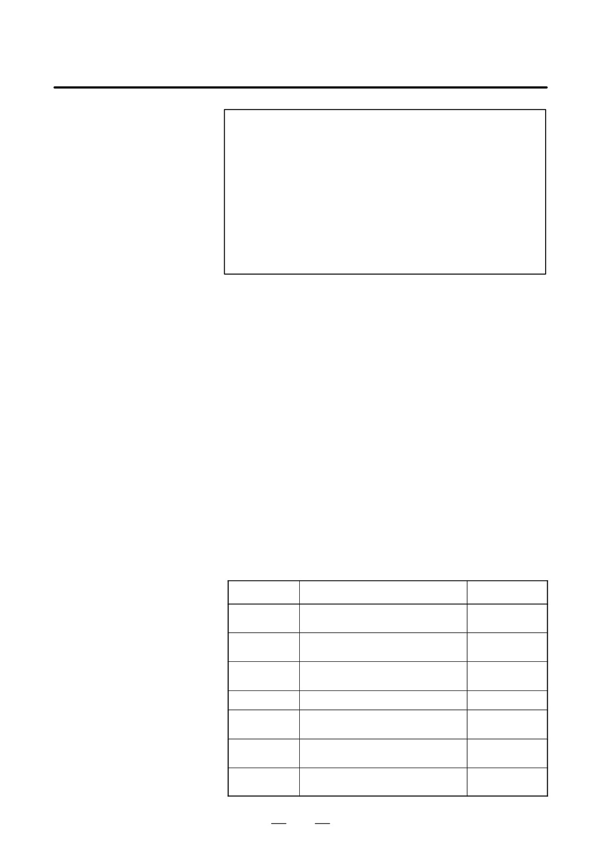
(1) Press the
SYSTEM
function key. Pressing the menu continuation key [
]
Data Sampling for
displays the [W.DGNS] soft key. Press this soft key to display the
Storage Type
WAVE DIAGNOS. (PARAMETER) screen.
Waveform Diagnosis
(2) Press the [W.MEM] soft key to display the WAVE DIAGNOS.
(MEMORY) screen. The operation selection soft keys appear.
The configuration of the operation selection soft keys is as follows:
WAVE DIAGNOS. (MEMORY)
O1234 N12345
CONDITION:
100
TRIGGER: G0123.4
DATA KINDS
SAMPLING AXIS
POS ERROR
XYZABCUV
MOTION CMD
XYZABCUV
CURRENT (%)
XYZABCUV
SPEED (RPM)
NONE
TORQUE CMD
NONE
HEAT SIMLT
XYZABCUV
SMPL TIME :
2. 0SEC
DATE
: MEMORY
EDIT **** *** ***
08:20:52
[SELECT] [
] [
] [
] [START]
(3) The configuration of the operation selection soft keys is as
follows:
[W.PRM] [W.GRPH] [ W.MEM ] [
] [
]
Press
[SELECT] [
] [
] [
] [START]
[
] [
] [PUNCH] [
] [
]
Fig. 1.10.4 Soft keys
(4) Using the cursor, set the necessary data items. To set the sampling
axes, position the cursor to the data item to be set, enter the names of
the axes for which data will be sampled for that data item, then press
[SELECT] or
INPUT
. The axis names are displayed to the right of the
data items.
Example) XYZ + [SELECT] or
INPUT
Once the sampling axes have been selected, the sampling period for each
axis is displayed. Subsequently pressing the [START] soft key starts data
sampling.
106
B-63525EN/02
1. DISPLAY AND OPERATION
CAUTION
1
Data items for which ***** is displayed cannot be set.
2
To change the sampling axes, enter new axis names then
press the [SELECT] soft key. Pressing the [SLELCT] soft
key without entering an axis name results in no sampling
axis being set.
3
If the sampling axes are changed during data sampling,
data sampling is stopped. In this case, press the [START]
soft key to restart data sampling for the new sampling axes.
4
Initially, no sampling axis is set.
5
When the sixth-type sampling data is spindle load meter
data (parameter No. 3121 = 1), set the axis name S.
D Storage data parameters
(1) Storage stop condition
100: Stops data storage upon the issue of a servo alarm.
101: Stops data storage upon the issue of a servo alarm or the
detection of the rising edge of the trigger signal.
102: Stops data storage upon the issue of a servo alarm or the
detection of the falling edge of the trigger signal.
The maximum stored data width is 32760 ms. If the storage stop
condition is not satisfied within 32760 ms, data is overwritten, starting
with the oldest data.
Parameter No. 3120 can be used to delay data storage being stopped
by a specified period (ms), after the issue of a servo alarm.
(2) Trigger: Set the PMC address and bit for the signal used to trigger the
stopping of data storage, when 101 or 102 is set for the stop condition.
Example) G0007.2: ST signal
(3) Data type: The following table lists the types of data for which a
waveform can be displayed.
Data type
Description
Units
POS ERROR
Servo error (8 ms) for the n-th axis
Pulses
(detection units)
MOTION CMD
Pulse distribution for the n-th axis
Pulses
(input increments)
CURRENT (%)
Torque for the n-th axis
% (relative to maxi-
mum current)
SPEED (RPM)
Actual speed for the n-th axis
min-1
TORQUE CMD
Command current for the n-th axis
% (relative to maxi-
mum current)
HEAT SIMLT
Thermal simulation data for the n-th axis
%
(when the parameter No.3121 is set to 0.)
(OVC alarm ratio)
LOAD METER
Load meter for the n-th spindle
% (relative to maxi-
(when the parameter No.3121 is set to 1.)
mum output)
107
1. DISPLAY AND OPERATION
B-63525EN/02
NOTE
With parameter No. 3121, choose whether the sixth-type
sampling data is thermal simulation data or spindle load
meter data. When spindle load meter is selected, the
spindle data of the first axis is stored with each path.
(4) Sampling axis: The axes along which data will be sampled are
displayed.
(5) Sampling period: The sampling period for each axis is displayed.
(6) Date of storage: While data is being sampled, MEMORY blinks in this
field. When data sampling stops, the date at that point appears in this
field.
Waveform diagnosis data of servo alarm format can be output to an I/O
1.10.5
device, as follows:
Outputting Waveform
1) Select EDIT mode.
Diagnosis Data
(Storage Type)
2) Press the
SYSTEM
key, then display the WAVE DIAGNOS. (MEMORY)
screen.
3) Press the [W.MEM],
, [PUNCH], and [EXEC] soft keys, in this
order.
For details of input/output to/from the FANUC Floppy Cassette or FA
Card, see “Output to FANUC Floppy Cassette or FA Card,” below.
WAVE DIAGNOSE (MEMORY)
O1234 N12345
CONDIGION:
100
TRIGGER: G0123.4
DATA KINDS
SAMPLING AXIS
POS ERROR
XYZABCUV
MOTION CMD
XYZABCUV
CURRENT (%)
XYZABCUV
SPEED (RPM)
NONE
TORQUE CMD
NONE
HEAT SIMLT
XYZABCUV
SMPL TIME :
2.0SEC
DATE
: 01/01/13
12:15:00
EDIT **** *** ***
12:15:52
[SELECT] [
] [
] [
] [START]
[
] [
] [PUNCH] [
] [
]
Press
[
] [
] [
] [ CAN ] [ EXEC ]
Press
108
B-63525EN/02
1. DISPLAY AND OPERATION
D Output to FANUC Floppy
1) Select EDIT mode.
Cassette or FA Card
2) Press the
SYSTEM
key, then display the WAVE DIAGNOS. (MEMORY)
screen.
3) Open the write protect tab on the floppy disk or card.
4) Press the [W.MEM],
, [PUNCH], and [EXEC] soft keys, in this
order.
The waveform diagnosis data is output to a file named WAVE
DIAGNOS, to which the number of the last file is assigned.
If a file named WAVE DIAGNOS already exists in the floppy disk or on
the card, P/S alarm 86 is issued. A floppy disk or card can contain only
one file for waveform diagnosis data. If the existing WAVE DIAGNOS
file contains unnecessary waveform diagnosis data of servo alarm format,
delete that file before attempting to output new data. The procedure for
deleting a file is described later.
D Directory display
The directory in the cassette or card is displayed by means of the
following procedure:
1) Select EDIT mode.
2) Press the
PROG
function key to select the program screen.
3) Press the continuous menu key
, then press [FLOPPY].
PAGE
4) Press page key
The directory is displayed.
D Deleting a file
A file stored on a cassette or card is deleted by means of the following
procedure:
1) Select EDIT mode.
2) Press the
PROG
function key to select the program screen.
3) Set the write protect switch on the cassette or card to enable writing.
4) Press [FLOPPY].
5) Press [DELETE].
6) Enter the file number, then press [F SET].
7) Press [EXEC].
The file corresponding to the specified file number is deleted. The
number of each file subsequent to the deleted file is decremented by
one.
109
1. DISPLAY AND OPERATION
B-63525EN/02
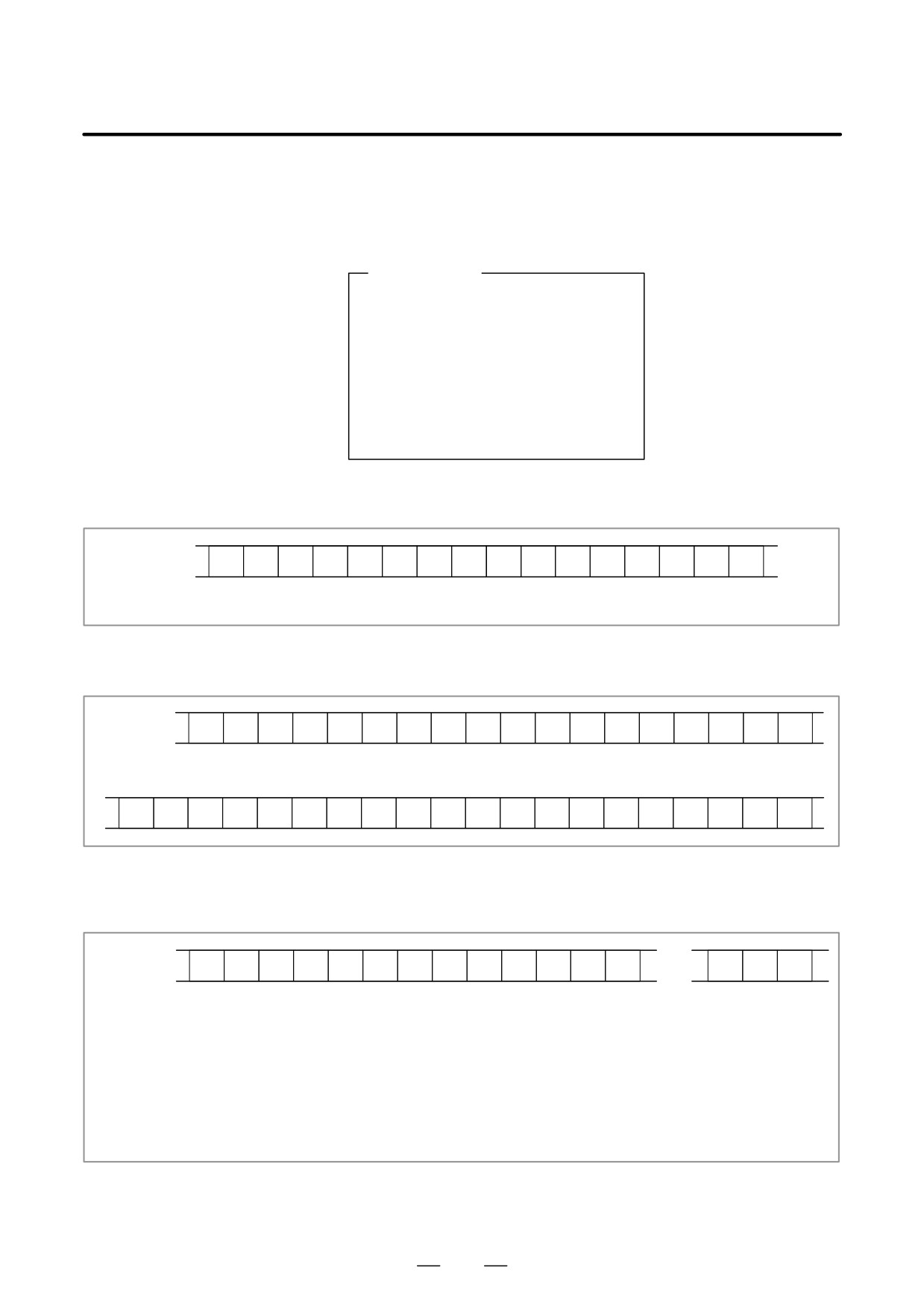
D Output format
In the servo alarm format, the header, date and time, selected axes, and
waveform diagnosis data are output in this order. Data items are identified
by ten identifier words. Output data other than the identifier words varies
with the data type.
T(identifier word)
T0 : Header
T60 : Positional deviation
T61 : Move command
T62 : Actual current
T63 : Actual speed
T64 : Command current
T65 : Thermal simulation
T66 : Load meter for the spindle
T68 : Selected axes
T69 : Date and time
1) Header
T
0
C
W
A
V
E
D
I
A
G
N
O
S
;
C: Data word
2) Data word
T
6
9
D
,
;
D *..*: Data Example: 12:14 59 seconds on June 23, 2001
T
6
9
D
2
0
0
1
0
6
2
3
,
1
2
1
4
5
9
;
3) Selected axes
T
6
8
P
*
*
D
,
*
*
,
to
*
*
,
P0: Positional deviation
P1: Actual speed
P2: Move command
P3: Command current
P4: Actual current
P5: Thermal simulation
D*.. *: Axis number (1 to 8)
110
B-63525EN/02
1. DISPLAY AND OPERATION
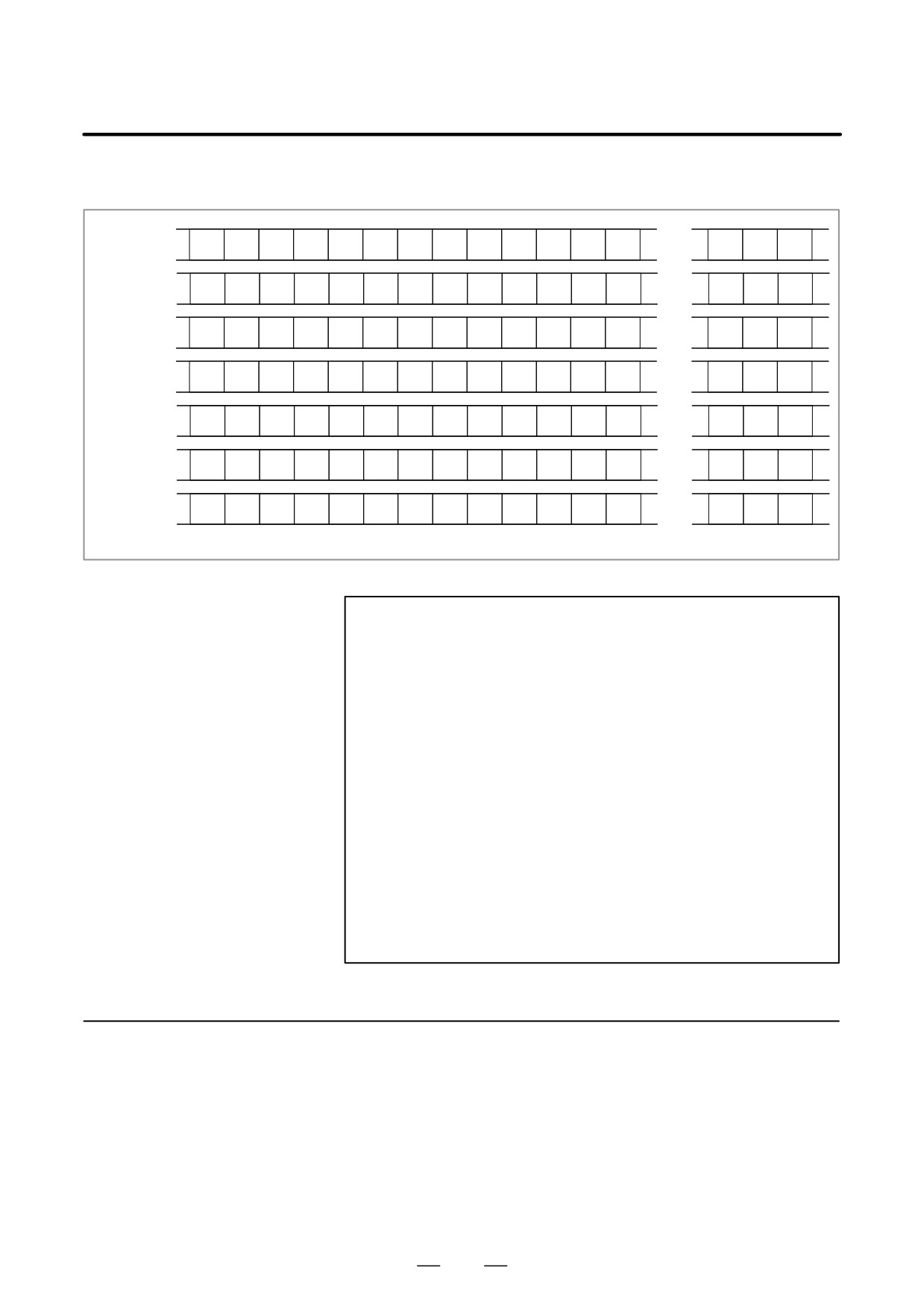
4) Waveform diagnosis data
T
6
0
D
,
,
,
to
,
T
6
1
D
,
,
,
to
,
T
6
2
D
,
,
,
to
,
T
6
3
D
,
,
,
to
,
T
6
4
D
,
,
,
to
,
T
6
5
D
,
,
,
to
,
T
6
6
D
*
,
,
,
to
,
D *..*: Waveform diagnosis data x number of axes
NOTE
1
Records are classified into header records and data
records.
2
“%” is used as an end-of-record code.
3
Each record starts with an identifier and ends with an
end-of-block code.
4
Either the ISO or EIA code system is used.
5
The output code type is specified with parameter ISO (bit 1
of No. 0100). For ISO code, parameter NCR (bit 3 of No.
0100) is used to specify whether the end-of-block code is
<LF> only, or a sequence of <LF> <CR> <CR>.
6
Parameter NFD (bit 7 of No. 01X1, where X is the channel
number) is used to specify whether a feed code is output
before and after the data.
7
No identifier word is output for a data item for which no axis
is selected.
8
The above file corresponds to a paper tape of about 200 m
in length.
1.10.6
(1) Once the storage is full, the oldest data is overwritten.
Notes
(2) Stored-type waveform diagnostic data is not lost, even when the
power is turned off.
(3) The waveform diagnostic function is disabled when parameter SGD
(bit 0 of No. 3112) is set to 0.
(4) Set the correct date and time using the setting screen.
111
1. DISPLAY AND OPERATION
B-63525EN/02
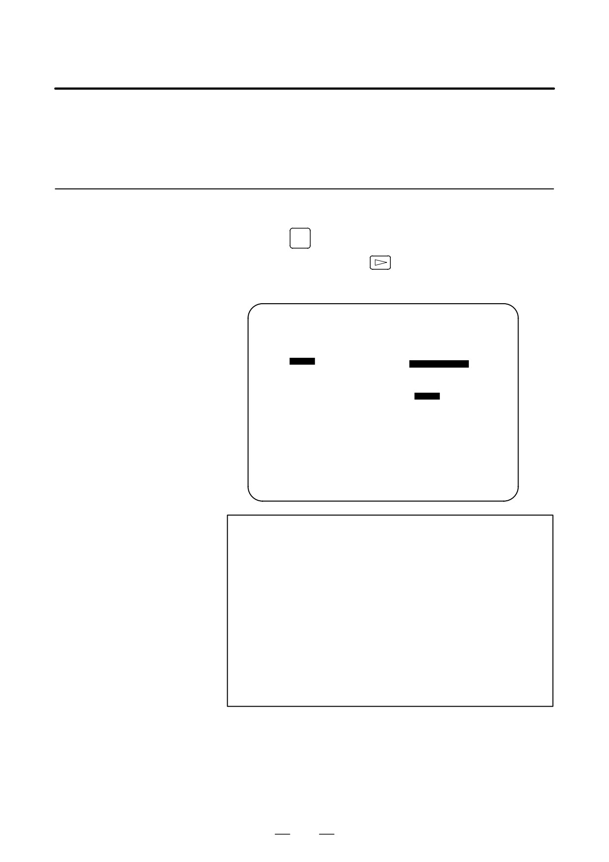
Load meter of the servo axis and the serial spindle and the speed meter
1.11
can be displayed.
OPERATING
MONITOR
1.11.1
1. Set a parameter to display operating monitor. (Bit 5 (OPM) of
parameter No.3111)
Display Method
2. Press the
POS
key to display the position display screen.
3. Press continuous menu key
, then soft key [MONI] is displayed.
4. Press the soft key [MONI], then the operating monitor screen is
displayed.
OPERATING MONITOR
O0001 N00001
(LOAD METER)
X :
80%
S1:
201%
Y :
* * * * *
0%
(SPEED METER RPM)
Z :
* * * * *
0% S1:
* * *
1500
PART COUNT
5
RUN TIME
0H15M
CYCLE TIME
0H 0M38S
ACT.F
3000 MM/M
S
0
T
0000
MEM STRT MTN ***
09:06:35
[
[ ABS ] [ REL ] [ ALL ] [ HNDL ] [ OPRT ]
CAUTION
1
The bar graph for the load meter shows load up to 200%.
2
The bar graph for the speed meter shows the ratio of the
current spindle speed to the maximum spindle speed
(100%). Although the speed meter normally indicates the
speed of the spindle motor, it can also be used to indicate
the speed of the spindle by setting bit 6. (OPS) of parameter
3111 to 1.
3
The servo axes for their load meters are displayed are set
to parameter No. 3151 to 3. If parameters 3151 to 3153 are
all zero, the load meter of the basic axes are displayed.
4
For color display, the bar of the load meter that exceed
100% shows purple color.
112
B-63525EN/02
1. DISPLAY AND OPERATION
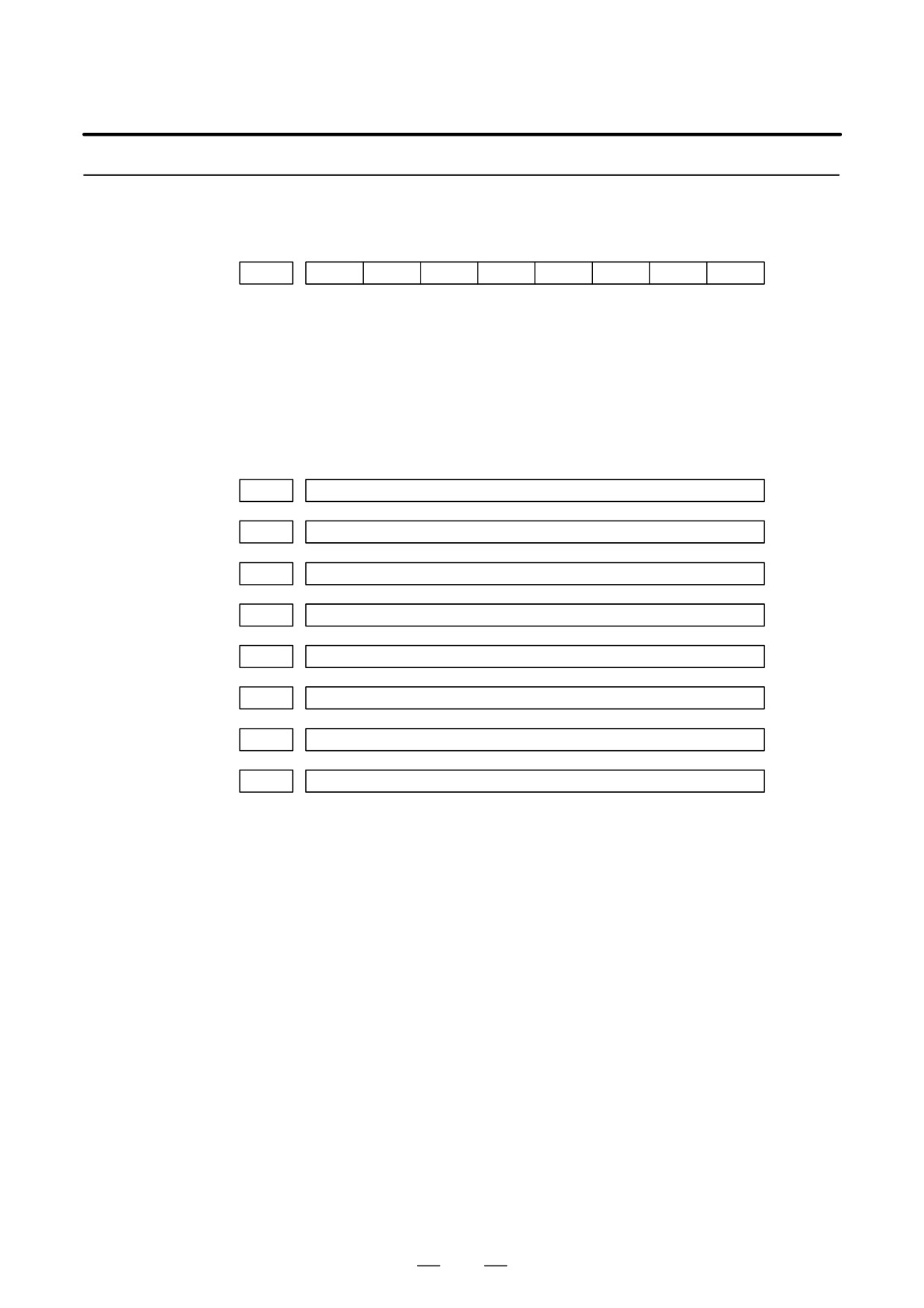
1.11.2
Parameters
#7
#6
#5
#4
#3
#2
#1
#0
DGN
3111
OPS
OPM
[Data type]
Bit
OPM
Operating monitor display is:
0 : Disabled
1 : Enabled
OPS
The speed meter on the operating monitor screen displays:
0 : Spindle motor speed
1 : Spindle speed
DGN
3151
Axis number for which the first servo motor load meter is displayed
DGN
3152
Axis number for which the second servo motor load meter is displayed
DGN
3153
Axis number for which the third servo motor load meter is displayed
DGN
3154
Axis number for which the fourth servo motor load meter is displayed
DGN
3155
Axis number for which the fifth servo motor load meter is displayed
DGN
3156
Axis number for which the sixth servo motor load meter is displayed
DGN
3157
Axis number for which the seventh servo motor load meter is displayed
DGN
3158
Axis number for which the eighth servo motor load meter is displayed
[Data type] Byte
[Valid data range] 0, 1, ... number of controlled axes
These parameters specify the numbers of the axes for which load meters
for servo motors are to be displayed. Up to eight load meters can be
displayed. Set 0 for those axes for which no load meter is to be displayed.
113
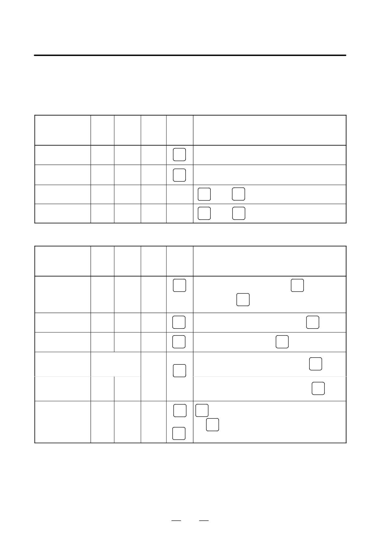
1. DISPLAY AND OPERATION
B-63525EN/02
1.12
LIST OF
OPERATIONS
Reset
Data
Param-
Func-
protec-
Function
eter
Mode
tion
Operation
tion
write=1
button
key
Resetting run hour
[(OPRT)] [RUNPRE]→[EXEC]
-
POS
Resetting no. of
[(OPRT)] [PTSPRE]→[EXEC]
machined parts
-
POS
Resetting OT alarm
At Pow-
-
P
and
CAN
er ON
Resetting alarm 100
-
-
CAN
and
RESET
Registration from MDI
Data
Param-
Func-
protec-
Function
eter
Mode
tion
Operation
tion
write=1
button
key
SYSTEM
Parameter no.→[NO.SRH]→Data→
INPUT
Inputting
MDI or
Ę
parameters
E.Stop
(PA-
→ PWE =0 →
RESET
RAM)
Inputting offset
OFFSET
OFF
-
SETTING
Offset number→[NO.SRH]→Offset value→
INPUT
values
Inputting setting
OFFSET
OFF
MDI
SETTING
Setting no.→[NO.SRH]Data→
INPUT
data
Input of PMC
parameters, counter
OFF or Ę
[PMCPRM]→[COUNTR] or [DATA]→Data→
INPUT
and data table
SYSTEM
MDI or
E.Stop
Inputting PMC
(PMC)
parameters
Ę
[PMCPRM]→[TIMER] or [KEEPRL]→Data→
INPUT
(Timer, keep relay)
POS
POS
(Display of relative coordinate)<AXIS>→ [ORIGIN]
Tool length
JOG
→
OFFSET
measurement
→
SETTING
→Jog the tool to measuring position
OFFSET
SETTING
Offset no.→[NO.SRH]→<AXIS>→[INP.C]
114
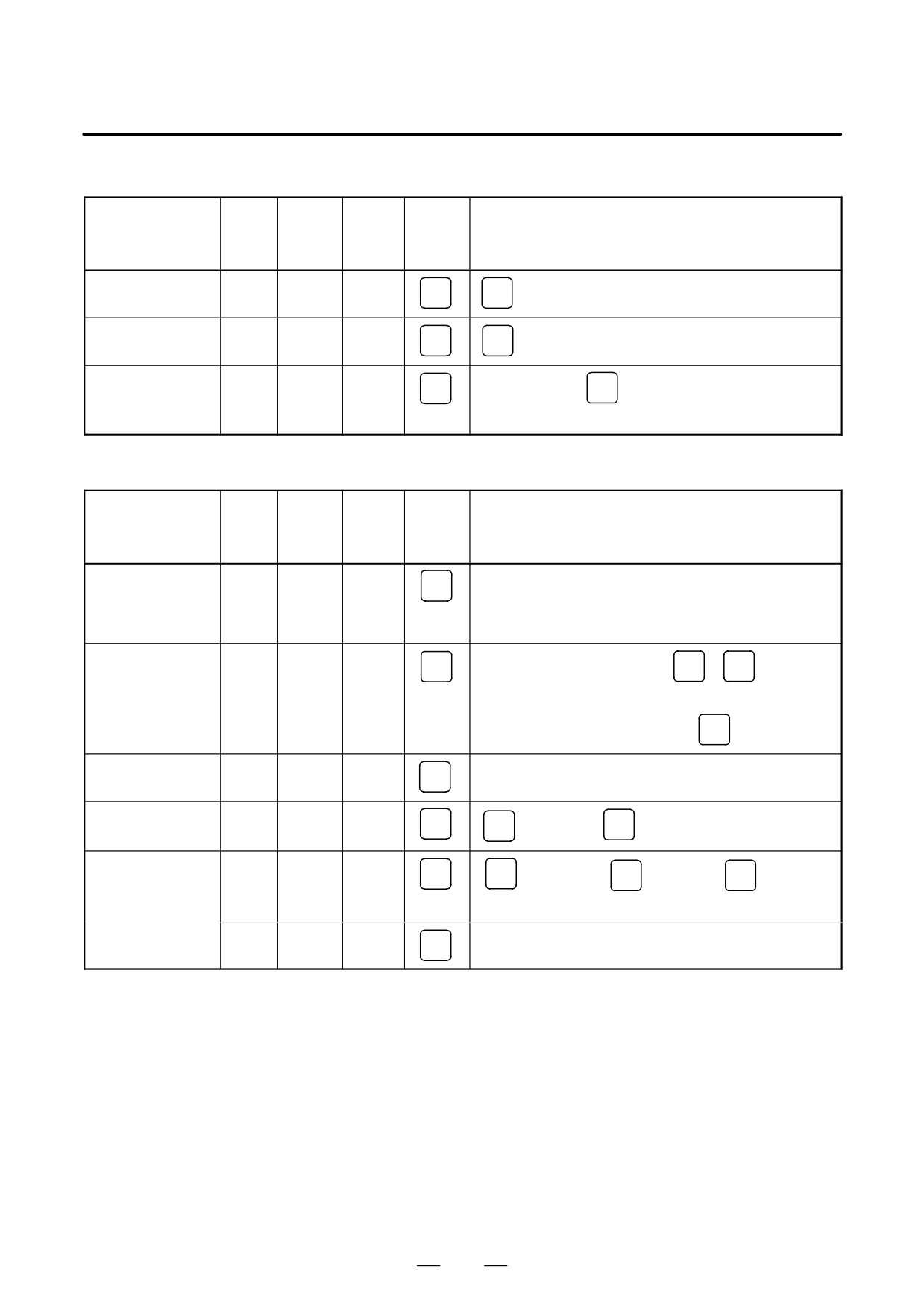
B-63525EN/02
1. DISPLAY AND OPERATION
Input/Output with FANUC Cassette
Data
Param-
Func-
protec-
Function
eter
Mode
tion
Operation
tion
write=1
button
key
Heading a file
EDIT
PROG
N
→File no.→[ " ]→[F SRH]→[EXEC]
Deleting a file
OFF
EDIT
PROG
N
→File no.→[ " ]→[DELETE→[EXEC]
Collating a program
EDIT
PROG
Heading a file→
O
→Program number→[(OPRT)]
→[ " ]→[READ]→[EXEC]
Inputting From FANUC Cassette
Data
Param-
Func-
protec-
Function
eter
Mode
tion
Operation
tion
write=1
button
key
Inputting
Ę
EDIT or
[(OPRT)]→[ " ]→[READ]→[EXEC]
SYSTEM
parameters
E.Stop
(PA-
RAM)
Inputting PMC
Ę
E.Stop
SYSTEM
INPUT
parameters
[
" ]→[I/O]→(CANNEL NO)
1
→
(PMC)
(DEVICE NAME) [FDCAS]→(KIND OF DATA) [PA-
RAM]→[READ]→(FILE NO) File no.
INPUT
→[EXEC]
Inputting offset
OFF
EDIT
(Heading a file no.)→[(OPRT)]→[ " ]→[READ]→[EXEC]
OFFSET
SETTING
values
Registering a
OFF
EDIT
PROG
→File no.→
INPUT
→[ " ]→[READ]→[EXEC]
program
N
Inputting macro
OFF
EDIT
PROG
N
→File no.→
INPUT
→[ " ]→
→
variables
O
Program no. → [READ]→[EXEC]
MEMO
<START>
PROG
RY
115
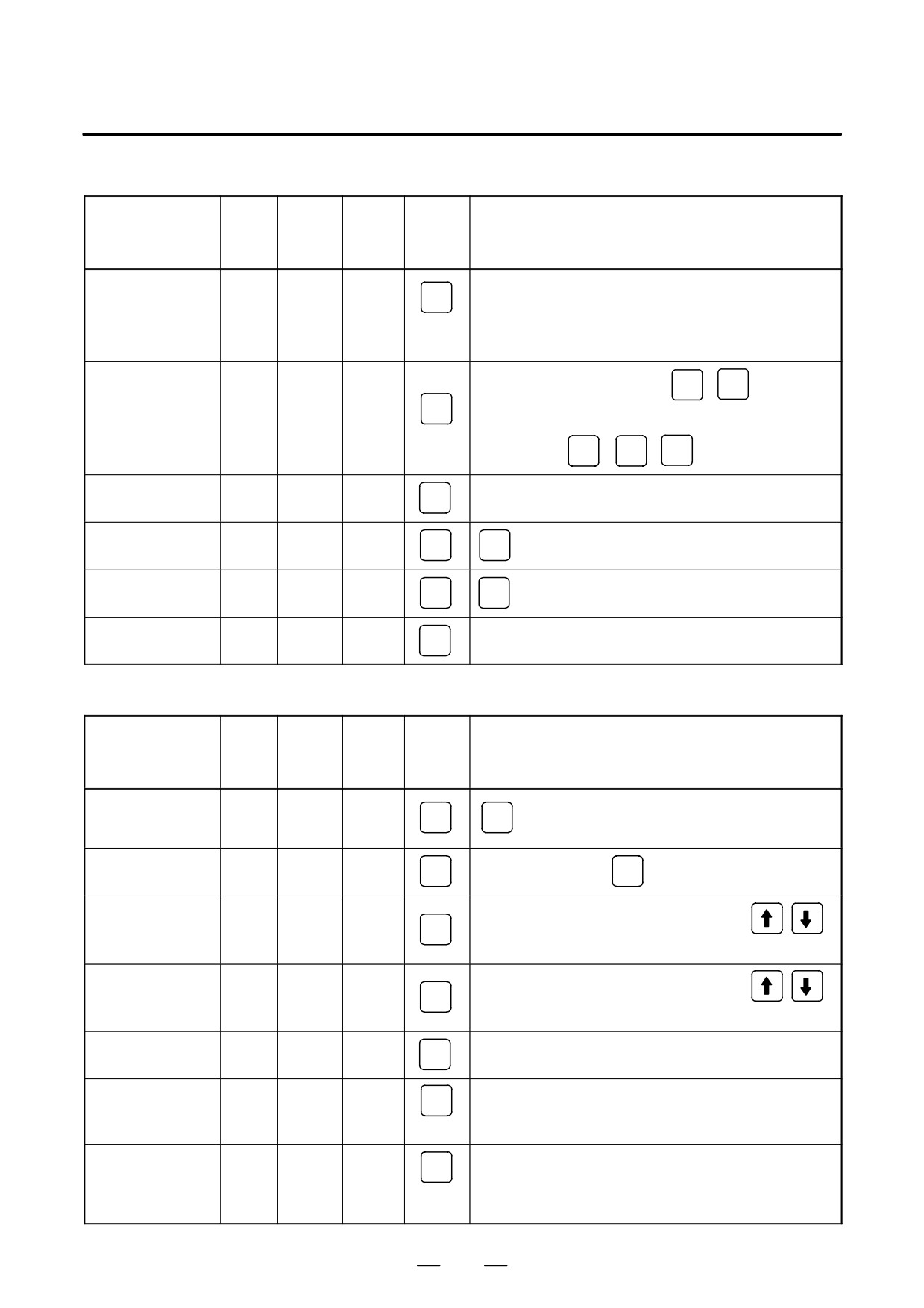
1. DISPLAY AND OPERATION
B-63525EN/02
Output to FANUC Cassette
Data
Param-
Func-
protec-
Function
eter
Mode
tion
Operation
tion
write=1
button
key
EDIT
[(OPRT)]→[ " ]→[PUNCH]→[EXEC]
or
SYSTEM
Output of
Emer-
parameter
(PA-
gency
RAM)
Stop
[
" ]→[I/O]→(CANNEL NO)
1
INPUT
→(DEVICE
Output of PMC
SYSTEM
EDIT
NAME) [FDCAS] →(KIND OF DATA) [PARAM] → [WRITE]
parameter
(PMC)
→ (FILE NO)
INPUT
→[EXEC]
1
[(OPRT)]→[ " ]→[PUNCH]→[EXEC]
OFFSET
Output of offset
EDIT
SETTING
Output of all
EDIT
PROG
O
→-9999→[ " ]→[PUNCH]→[EXEC]
programs
Output of one
EDIT
PROG
O
→Program no.→[ " ]→[PUNCH]→[EXEC]
program
Output of macro
[
" ]→[MACRO]→[(OPRT)]→[ " ]→[PUNCH]→[EXEC]
OFFSET
EDIT
SETTING
variables
Search
Data
Param-
Func-
protec-
Function
eter
Mode
tion
Operation
tion
write=1
button
key
Searching a
MEMO
program number
RY
PROG
O
→Program no.→[O SRH]
or EDIT
Searching a
MEMO
PROG
Program no. search→
N
→Sequence number→[NSRH]
sequence number
RY
Searching an
Data to be searched→[SRH↑] or[SRH↓] or
address word
EDIT
PROG
(cursor key)
Searching an
Address to be searched [SRH↑] or[SRH↓] or
address only
EDIT
PROG
(Cursor key)
Searching an offset
Offset no.→[NO.SRH]
OFFSET
-
SETTING
number
Searching a
Diagnostic number→[NO.SRH]
SYSTEM
diagnostic number
-
(DGNOS)
Searching a
Parameter no.→[NO.SRH]
SYSTEM
parameter number
-
(PA-
RAM)
116
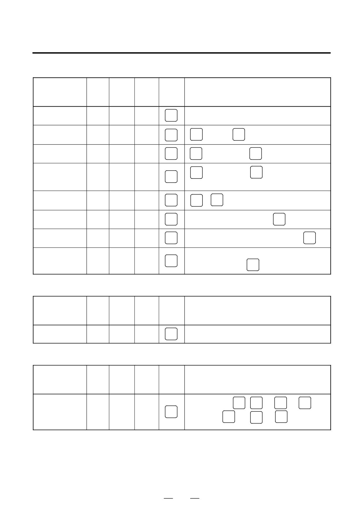
B-63525EN/02
1. DISPLAY AND OPERATION
Edit
Data
Param-
Func-
protec-
Function
eter
Mode
tion
Operation
tion
write=1
button
key
Display of memory
[LIB]
EDIT
PROG
capacity used
Deleting all
OFF
EDIT
PROG
O
→-9999→
DELETE
programs
OFF
Deleting a program
EDIT
PROG
O
→Program no.→
DELETE
Deleting several
N
→Sequence no.→
DELETE
OFF
EDIT
PROG
blocks
(Deleted up to a block with a specified sequence no.)
OFF
Deleting a block
EDIT
PROG
EOB
→
DELETE
OFF
Deleting a word
EDIT
PROG
Searching a word to be deleted→
DELETE
OFF
Changing a word
EDIT
PROG
Searching a word to be changed→New Data→
ALTER
OFF
Searching a word immediately before a word to be
Inserting a word
EDIT
PROG
searched→New Data→
INSERT
Collation
Data
Param-
Func-
protec-
Function
eter
Mode
tion
Operation
tion
write=1
button
key
ON
[(OPRT)]→[ " ]→[READ]→[EXEC]
Collating memory
EDIT
PROG
Playback
Data
Param-
Func-
protec-
Function
eter
Mode
tion
Operation
tion
write=1
button
key
TEACH
Jog the machine→
X
,
or
Z
→
INSERT
-IN
Y
Input of NC data
JOG/
PROG
→ NC data →
INSERT
→
→
INSERT
HAN-
EOB
DLE
117
1. DISPLAY AND OPERATION
B-63525EN/02
Clear
Data
Param-
Func-
prote-
Function
eter
Mode
tion
Operation
ction
write=1
key
key
Memory all clear
RESET
DELETE
M/T
:
AND
On 2path are controlled
On 2path are controlled
At
power
CAN
Path1 :
AND
1
ON
Path2 :
CAN
AND
2
Loader is controlled
:
CAN
AND
5
Parameter/offset
M/T
:
RESET
clear
On 2path are controlled
At
Path1 :
RESET
AND
1
f
Power
Path2 :
RESET
AND
ON
2
Loader is controlled
:
RESET
AND
5
(Parameter
only)
Clearing a program
M/T
:
DELETE
On 2path are controlled
At
DELETE
1
Path1 :
AND
f
Power
ON
Path2 :
DELETE
AND
2
Loader is controlled
:
RESET
AND
5
Program under
edition at power
-
PROG
AND
RESET
off(PS101)
PMC RAM *
Main CPU :
AND
(O)
At
X
0
Power
ON
Loader is controlled
:
X
AND
5
Additional SRAM
M/T
:
O
(O) AND
DELETE
area clear
At
On 2path are controlled
Power
ON
Path1 :
O
(O) AND
1
Path2 :
(O) AND
O
2
* PMC ladder program is not cleard in FROM.
118
B-63525EN/02
1. DISPLAY AND OPERATION
Manual operation
KEY
PWE
Func-
Function
Mode
Operation
SW
=1
tion key
Manual refer-
Turn on Reference point return switch ³ Turn on +X, -X, +Z, or -Z ³
ence point
JOG
Reference point return switch LED lit.
return
Turn on +X, -X, +Z, or -Z ³ Use JOG FEEDRATE to set jog feedrate
Jog feed
JOG
³ Press Rapid traverse button, if required.
Incremental
Use Move distance selection switch to select move distance ³ Turn on
INC
feed
+X, -X, +Z, or -Z ³ Press Rapid traverse button, if required.
Use Axis selection switch to select axis to be operated ³ Use Handle
Manual
HND
magnification selection to select magnification ³ Turn manual pulse
handle feed
generator.
Display
Function
KEY
PWE
Func-
Mode
Operation
SW
=1
tion key
Amount of
program
EDIT
PROG
[ DIR ]
memory in
use
Command
Command value being executed, and previously specified modal value
value display
[CURRNT]
Command value being executed, and next command value to be
executed
[ NEXT ]
MEM
Command value entered from MDI, and previously specified modal
or
PROG
value
MDI
[ MDI ]
Program in memory being executed
[PRGRM]
Executable blocks in memory and current position
[CHECK]
Current-
Representation of the position in the workpiece coordinate system
position
display
[ ABS ]
Representation of the position in the relative coordinate system
POS
[ REL ]
General position indication
[ ALL ]
Alarm display
—
MESSAGE
[ALARM ] when an alarm condition has occurred.
119
1. DISPLAY AND OPERATION
B-63525EN/02
Function
KEY
PWE
Func-
Mode
Operation
SW
=1
tion key
Alarm history
MESSAGE
[HISTRY]
display
Screen erase
Press the
CAN
and function keys simultaneously. The function key
—
—
causes re-display.
Screen
switching
SHIFT
and
HELP
between NC
and loader
Graphics functions (T series)
KEY
PWE
Func-
Function
Mode
Operation
SW
=1
tion key
Parameter
GRAPH
[G.PRM]
setting
Select a graphics drawing screen.
[GRAPH]
Begins and ends drawing.
During automatic operation or manual operation
Tool path
GRAPH
drawing
Erase a drawing screen.
[(OPRT)]
³ [ERASE ]
Enlarge graphics.
[ ZOOM ]
NOTE
For the small-size MDI, read the
GRAPH
function key in this
CUSTOM
table as the
GRAPH
function key.
Graphics function (M series)
Function
KEY
PWE
Func-
Mode
Operation
SW
=1
tion key
Parameter
GRAPH
[PARAM]
setting
Tool path
Select a graphics drawing screen.
drawing
[GRAPH]
GRAPH
Begin and end drawing.
During automatic operation or manual operation
120
B-63525EN/02
1. DISPLAY AND OPERATION
Function
KEY
PWE
Func-
Mode
Operation
SW
=1
tion key
Tool path dia-
Press the
GRAPH
key several times ³ Display “PATH GRAPHIC
gram data
setting
GRAPH
(PARAMETER)” screen ³ [PARAM ] ³ Enter numerals using numeric
keys ³
INPUT
Tool path
GRAPH
drawing
Press the
key several times ³ Display “PATH GRAPHIC
(PARAMETER)” screen ³ [EXEC] ³ [(OPRT)] ³ [ AUTO ] or [START]
Suspend drawing
[ STOP ]
MEM
GRAPH
Execute.
[START]
Suspend
drawing
Draw starting at the top of the program.
[REWIND] ³ [START ]
Enlarging
Press the
GRAPH
key several times ³ Display “PATH GRAPHIC
part of the
tool path
GRAPH
(PARAMETER)” screen ³ [SCALE] ³ [(OPRT)][²][³][±][°] ³
P c
drawing
or
M #
³ [EXEC]
Current-tool
Press the
GRAPH
key several times ³ Display “SOLID GRAPHIC
position mark
GRAPH
display
(PARAMETER)” screen ³ [ POS ]
Machining
Press the
GRAPH
key several times ³ “SOLID GRAPHIC
profile
drawing data
GRAPH
(PARAMETER)” screen ³ Enter numerals using numeric keys
setting
³
INPUT
Blank figure
Press the
GRAPH
key several times ³ “SOLID GRAPHIC
drawing
GRAPH
(PARAMETER)” screen ³ [BLANK ] ³ [(OPRT)] ³ [ ANEW ] ³
[+ ROT][- ROT][+TILT ][-TILT ]
Machining
Press the
GRAPH
key several times ³ “SOLID GRAPHIC
profile draw-
ing
(PARAMETER)” screen ³ [EXEC] ³ [(OPRT)] ³ [ A.ST ] or [ F.ST ]
Suspend drawing
[ STOP ]
MEM
GRAPH
Execute.
[ A.ST ] or [ F.ST ]
After drawing
is suspended
Display the start of part program.
[REWIND] ³ [ A.ST ] or [ F.ST ]
121