FANUC Series 16i/160i/160is-MODEL B, Series 18i/180i/180is-MODEL B, Series 21i/210i/210is-MODEL B. MAINTENANCE MANAUL - page 3
1. DISPLAY AND OPERATION
B-63525EN/02
1.4.2.3
The system alarm history screen (detail screen) displays information
items such as registers and stacks involved when a system alarm is issued.
System alarm history
screen (detail screen)
The following items are displayed:
1. System alarm occurrence date and time
2. System alarm number
3. System alarm message (No message is displayed for some system
alarms.)
4. System alarm occurrence series and edition
5. Number of display pages
6. General-purpose resistor, pointer index register, segment register,
task register, LDT register, flag register, interrupt source, error
code, error address
7. Contents of stacks (up to 32 stacks)
8. Contents of stacks of privilege level 3 (up to 48 stacks)
9. NMI information
You can switch among the information items 6 to 9 by the page keys
PAGE
PAGE
Pressing the [RETURN] soft key returns the screen display to the state
alarm history list screen.
SYSTEM ALARM HISTORY
O1234 N12345
2
2001-03-11 07:23:07
BDH1-01(1/4)
973 NON MASK INTERRUPT
EAX
EBX
ECX
EDX
00000000
00930063
000003E0
00000040
ESI
EDI
EBP
ESP
00000010
009404E0
0000FFB4
0000FFDC
SS
DS
ES
FS
GS
TR
LDTR
06D8 0338 0248 0440 0338 0628 0028
EFLAGS
VECT
ERRC
ERROR-ADDRESS
00003046
FFFF
0000
03E0:000009BC
EDIT **** *** ***
08:20:52
[ SELECT ][ RETURN ][ CLEAR ][
][
]
(Detail display screen 1)
32
B-63525EN/02
1. DISPLAY AND OPERATION
SYSTEM ALARM HISTORY
O1234 N12345
2
2001-03-11 07:23:07
BDH1-01(2/4)
973 NON MASK INTERRUPT
STACK
(PL0)
3646 0338 7CBA 0001 0958 FFF8 0068 0063
0346 0000 0000 02BC 08F8 52F1 2438 0338
0580 0440 0580 001F 03C0 0214 0780 0FFF
0000 0000 0000 0000 0000 0000 0000 0000
EDIT **** *** ***
08:20:52
[ SELECT ][ RETURN ][ CLEAR ][
][
]
(Detail display screen 2)
SYSTEM ALARM HISTORY
O1234 N12345
2
2001-03-11 07:23:07
BDH1-01(3/4)
973 NON MASK INTERRUPT
STACK!(PL3)
SS:ESP3 =0804:00007C50
CS:EIP =1350:00001234
1008 1408 0001 0002 0003 0004 1008 FFE4
1008 3678 00FA 0024 0000 0000 0000 0000
0000 0000 0000 0000 0000 0000 0000 0000
0000 0000 0000 0000 0000 0000 0000 0000
0000 0000 0000 0000 0000 0000 0000 0000
0000 0000 0000 0000 0000 0000 0000 0000
EDIT **** *** ***
08:20:52
[ SELECT ][ RETURN ][ CLEAR ][
][
]
(Detail display screen 3)
SYSTEM ALARM HISTORY
O1234 N12345
2
2001-03-11 07:23:07
BDH1-01(4/4)
973 NON MASK INTERRUPT
NMIC
00000000
00000000
00000000
00000000
SVL
11111111
11111111
SVR
11111111
11111111
11111111
11111111
11111111
11111111
11111111
11111111
ADRS
007F0000
EDIT **** *** ***
08:20:52
[ SELECT ][ RETURN ][ CLEAR ][
][
]
(Detail display screen 4)
33
1. DISPLAY AND OPERATION
B-63525EN/02
CAUTION
1 In the case of an NMI on other than the main board, the
registers of detail display screen 1, and the contents of detail
display screen 2 and detail display screen 3 are displayed.
SYSTEM ALARM HISTORY
O1234 N12345
2
2001-03-11 07:23:07
BDH1-01(1/1)
972 NMI OCUURRED IN OTHER MODULE
SLOT>
02
0080415F
<1>
<2>
EDIT **** *** ***
08:20:52
[ SELECT ][ RETURN ][ CLEAR ][
][
]
(Detail display screen 5)
<1> NMI occurrence slot number
<2> Message address set with the NMI occurrence slot (string address)
SYSTEM ALARM HISTORY
O1234 N12345
2
2001-03-11 07:23:07
BDH1-01(1/1)
900 ROM PARITY
00000000
00000000
<1>
EDIT **** *** ***
08:20:52
[ SELECT ][ RETURN ][ CLEAR ][
][
]
(Detail display screen 6)
<1> ROM parity cause
Basic ROM
2F(h)
(800000A97FFFF)
Additional ROM
40(h)
(A00000AA3FFFF)
OMM ROM
80(h)
Servo ROM
100(h)
Built in MMC ROM
200(h)
Online Custom Screen
400(h)
34
B-63525EN/02
1. DISPLAY AND OPERATION
1.4.2.4
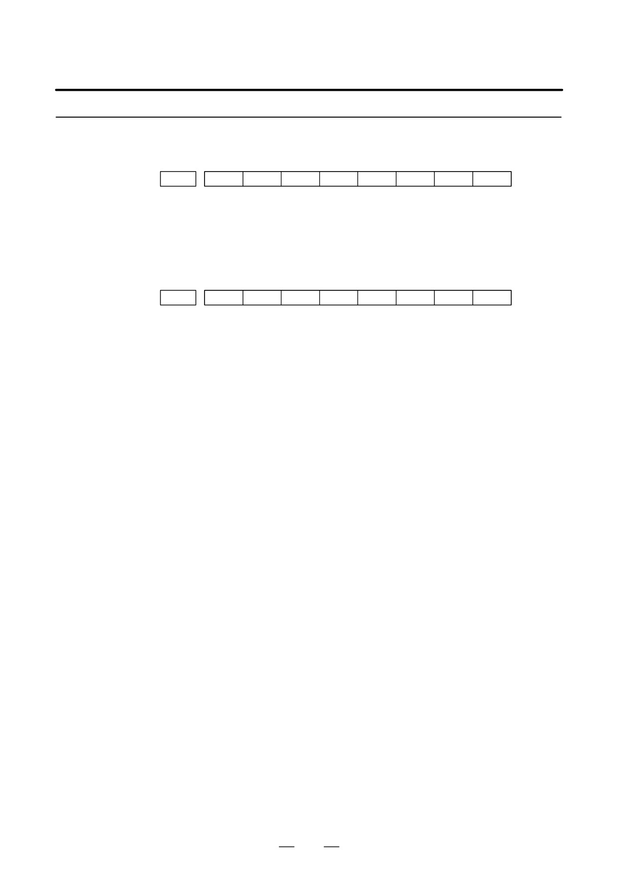
Parameter
#7
#6
#5
#4
#3
#2
#1
#0
3103
NMH
[Data type] Bit
NMH The system alarm history screen is:
0 : Not displayed.
1 : Displayed.
#7
#6
#5
#4
#3
#2
#1
#0
3110
OPC
[Data type] Bit
OPC On the operation history screen, the [CLEAR] soft key is:
0 : Not enabled.
1 : Enabled.
35
1. DISPLAY AND OPERATION
B-63525EN/02
This function enables the saving of external operator messages as a
1.5
record.
EXTERNAL
The record can be viewed on the external operator message history screen.
OPERATOR
MESSAGES
RECORD
1.5.1
(1) Press the
MESSAGE
function key.
Screen Display
(2) Press the rightmost soft key [>>].
[ALARM] [MGS] [HISTRY] [
] [ (OPRT) ]>>
↑
(3) Press the [MSGHIS] soft key.
(4) To display the previous or subsequent screen, press the
or PAGE
PAGE
key.
MESSAGE HISTORY
O1234 N12345
→ Date,
time, and
01/04/01 17:25:00
PAGE : 1
page
No. ****
→ Message
No.
Up to 255 characters
Display
range
MEM STRT MTN FIN ALM 17:25:00
[
][ MSGHIS ][
][
][
]
1.5.2
(1) The recorded external operator message can be deleted by setting the
MMC bit (bit 0 of parameter 3113) to 1.
Deletion of External
Pressing the [CLEAR] soft key erases all the records of the external
Operator Messages
operator message.
Record
(2) The MS1 and MS0 bits (bits 7 and 6 of parameter 3113) specify the
number of records to be displayed on the external operator message
history screen. When the bits are changed, all external operator
message records retained up to that point are erased.
36
B-63525EN/02
1. DISPLAY AND OPERATION
1.5.3
Parameter
#7
#6
#5
#4
#3
#2
#1
#0
3113
MS1
MS0
MHC
#0 (MHC)
The records of an external operator message:
0 : Cannot be erased.
1 : Can be erased.
#6, #7 (MS0,MS1)
These bits set the number of characters to be retained in each record of an
external operator message, as well as the number of records, as shown in
the following table:
MS1
MS0
Number of charac-
Number of records
ters in each record
0
0
255
8
0
1
200
10
1
0
100
18
1
1
50
32
* An external operator message of up to 255 characters can be specified.
Combining the MS1 bit and MS0 bit (bits 7 and 6 of parameter No.
3113) selects the number of records by limiting the number of
characters to be retained as the record of an external operator message.
#7
#6
#5
#4
#3
#2
#1
#0
3112
OMH
#2 (OMH)
The external operator message history screen is:
0 : Not displayed.
1 : Displayed.
NOTE
After setting this parameter, briefly turn the power off, then
on again.
1.5.4
When the number of an external operator message is specified, the system
starts updating the records of the specified message. The system
Notes
continues to perform update until another external operator message is
specified or until an instruction to delete the records of the external
operator message is specified.
37
1. DISPLAY AND OPERATION
B-63525EN/02
This function displays the key and signal operations performed by the
1.6
operator upon the occurrence of a fault or the output of an alarm, together
OPERATION
with the corresponding alarms.
HISTORY
This function records the following data:
(1) MDI key operations performed by the operator
(2) Status changes (ON/OFF) of input and output signals (selected signals
only)
(3) Details of alarms
(4) Time stamp (date and time)
1.6.1
Parameter Setting
#7
#6
#5
#4
#3
#2
#1
#0
3106
OHS
OPH
[Data type]
Bit
OPH
The operation history screen is:
0 : Not displayed.
1 : Displayed.
OHS
The operation history is:
0 : Sampled.
1 : Not sampled.
3122
Interval at which the clock time is recorded in the operation history
[Data type]
Word
[Units of data]
Minutes
[Valid data range]
0 to 1439
The clock time is recorded to the operation history at specified intervals.
If zero is set as the interval, ten minutes is assumed. The time is recorded
only when data is recorded within the corresponding interval.
#7
#6
#5
#4
#3
#2
#1
#0
3206
PHS
[Data type]
Bit
PHS
Setting and display on the operation history signal selection screen and
the parameters (No. 12801 through No. 128900) are:
0 : Not linked.
1 : Linked.
38
B-63525EN/02
1. DISPLAY AND OPERATION
12801
Number of a signal symbol table for selecting an operation history signal (01)
12802
Number of a signal symbol table for selecting an operation history signal (02)
12803
Number of a signal symbol table for selecting an operation history signal (03)
12804
Number of a signal symbol table for selecting an operation history signal (04)
12805
Number of a signal symbol table for selecting an operation history signal (05)
12806
Number of a signal symbol table for selecting an operation history signal (06)
12807
Number of a signal symbol table for selecting an operation history signal (07)
12808
Number of a signal symbol table for selecting an operation history signal (08)
12809
Number of a signal symbol table for selecting an operation history signal (09)
12810
Number of a signal symbol table for selecting an operation history signal (10)
12811
Number of a signal symbol table for selecting an operation history signal (11)
12812
Number of a signal symbol table for selecting an operation history signal (12)
12813
Number of a signal symbol table for selecting an operation history signal (13)
12814
Number of a signal symbol table for selecting an operation history signal (14)
12815
Number of a signal symbol table for selecting an operation history signal (15)
12816
Number of a signal symbol table for selecting an operation history signal (16)
12817
Number of a signal symbol table for selecting an operation history signal (17)
12818
Number of a signal symbol table for selecting an operation history signal (18)
12819
Number of a signal symbol table for selecting an operation history signal (19)
12820
Number of a signal symbol table for selecting an operation history signal (20)
[Data type] Byte
[Valid data range] 1 to 10
Set the number of a symbol table including a signal of which operation
history is to be recorded for operation history channel (01) to (20) as
follows:
1
: G0
to G255
2
: G1000
to G1255
3
: F0
to F255
4
: F1000
to F1255
5
: Y0
to Y127
6
: X0
to X127
9
: G2000
to G2255
10 : F2000
to F2255
39
1. DISPLAY AND OPERATION
B-63525EN/02
12841
Number of a signal selected as an operation history signal (01)
12842
Number of a signal selected as an operation history signal (02)
12843
Number of a signal selected as an operation history signal (03)
12844
Number of a signal selected as an operation history signal (04)
12845
Number of a signal selected as an operation history signal (05)
12846
Number of a signal selected as an operation history signal (06)
12847
Number of a signal selected as an operation history signal (07)
12848
Number of a signal selected as an operation history signal (08)
12849
Number of a signal selected as an operation history signal (09)
12850
Number of a signal selected as an operation history signal (10)
12851
Number of a signal selected as an operation history signal (11)
12852
Number of a signal selected as an operation history signal (12)
12853
Number of a signal selected as an operation history signal (13)
12854
Number of a signal selected as an operation history signal (14)
12855
Number of a signal selected as an operation history signal (15)
12856
Number of a signal selected as an operation history signal (16)
12857
Number of a signal selected as an operation history signal (17)
12858
Number of a signal selected as an operation history signal (18)
12859
Number of a signal selected as an operation history signal (19)
12860
Number of a signal selected as an operation history signal (20)
[Data type] Word
[Valid data range] 0 to 255
Set the number of a signal of which operation history is to be recorded for
operation history channel (01) to (20) with a value between 0 and 255.
40
B-63525EN/02
1. DISPLAY AND OPERATION
#7
#6
#5
#4
#3
#2
#1
#0
12881
RB7
RB6
RB5
RB4
RB3
RB2
RB1
RB0
History record bit settings for an operation history signal (01)
#7
#6
#5
#4
#3
#2
#1
#0
12882
RB7
RB6
RB5
RB4
RB3
RB2
RB1
RB0
History record bit settings for an operation history signal (02)
#7
#6
#5
#4
#3
#2
#1
#0
12883
RB7
RB6
RB5
RB4
RB3
RB2
RB1
RB0
History record bit settings for an operation history signal (03)
#7
#6
#5
#4
#3
#2
#1
#0
12884
RB7
RB6
RB5
RB4
RB3
RB2
RB1
RB0
History record bit settings for an operation history signal (04)
#7
#6
#5
#4
#3
#2
#1
#0
12885
RB7
RB6
RB5
RB4
RB3
RB2
RB1
RB0
History record bit settings for an operation history signal (05)
#7
#6
#5
#4
#3
#2
#1
#0
12886
RB7
RB6
RB5
RB4
RB3
RB2
RB1
RB0
History record bit settings for an operation history signal (06)
#7
#6
#5
#4
#3
#2
#1
#0
12887
RB7
RB6
RB5
RB4
RB3
RB2
RB1
RB0
History record bit settings for an operation history signal (07)
#7
#6
#5
#4
#3
#2
#1
#0
12888
RB7
RB6
RB5
RB4
RB3
RB2
RB1
RB0
History record bit settings for an operation history signal (08)
#7
#6
#5
#4
#3
#2
#1
#0
12889
RB7
RB6
RB5
RB4
RB3
RB2
RB1
RB0
History record bit settings for an operation history signal (09)
#7
#6
#5
#4
#3
#2
#1
#0
12890
RB7
RB6
RB5
RB4
RB3
RB2
RB1
RB0
History record bit settings for an operation history signal (10)
#7
#6
#5
#4
#3
#2
#1
#0
12891
RB7
RB6
RB5
RB4
RB3
RB2
RB1
RB0
History record bit settings for an operation history signal (11)
#7
#6
#5
#4
#3
#2
#1
#0
12892
RB7
RB6
RB5
RB4
RB3
RB2
RB1
RB0
History record bit settings for an operation history signal (12)
#7
#6
#5
#4
#3
#2
#1
#0
12893
RB7
RB6
RB5
RB4
RB3
RB2
RB1
RB0
History record bit settings for an operation history signal (13)
#7
#6
#5
#4
#3
#2
#1
#0
12894
RB7
RB6
RB5
RB4
RB3
RB2
RB1
RB0
History record bit settings for an operation history signal (14)
#7
#6
#5
#4
#3
#2
#1
#0
12895
RB7
RB6
RB5
RB4
RB3
RB2
RB1
RB0
History record bit settings for an operation history signal (15)
41
1. DISPLAY AND OPERATION
B-63525EN/02
#7
#6
#5
#4
#3
#2
#1
#0
12896
RB7
RB6
RB5
RB4
RB3
RB2
RB1
RB0
History record bit settings for an operation history signal (16)
#7
#6
#5
#4
#3
#2
#1
#0
12897
RB7
RB6
RB5
RB4
RB3
RB2
RB1
RB0
History record bit settings for an operation history signal (17)
#7
#6
#5
#4
#3
#2
#1
#0
12898
RB7
RB6
RB5
RB4
RB3
RB2
RB1
RB0
History record bit settings for an operation history signal (18)
#7
#6
#5
#4
#3
#2
#1
#0
12899
RB7
RB6
RB5
RB4
RB3
RB2
RB1
RB0
History record bit settings for an operation history signal (19)
#7
#6
#5
#4
#3
#2
#1
#0
12900
RB7
RB6
RB5
RB4
RB3
RB2
RB1
RB0
History record bit settings for an operation history signal (20)
[Data type] Bit
RB7 to RB0
For the signal set in channel (01) to (20), of which operation history is to
be recorded, the history of each bit is:
0 : Not recorded. (The history of this bit is not recorded.)
1 : Recorded. (The history of this bit is recorded.)
42
B-63525EN/02
1. DISPLAY AND OPERATION
1.6.2
Screen Display
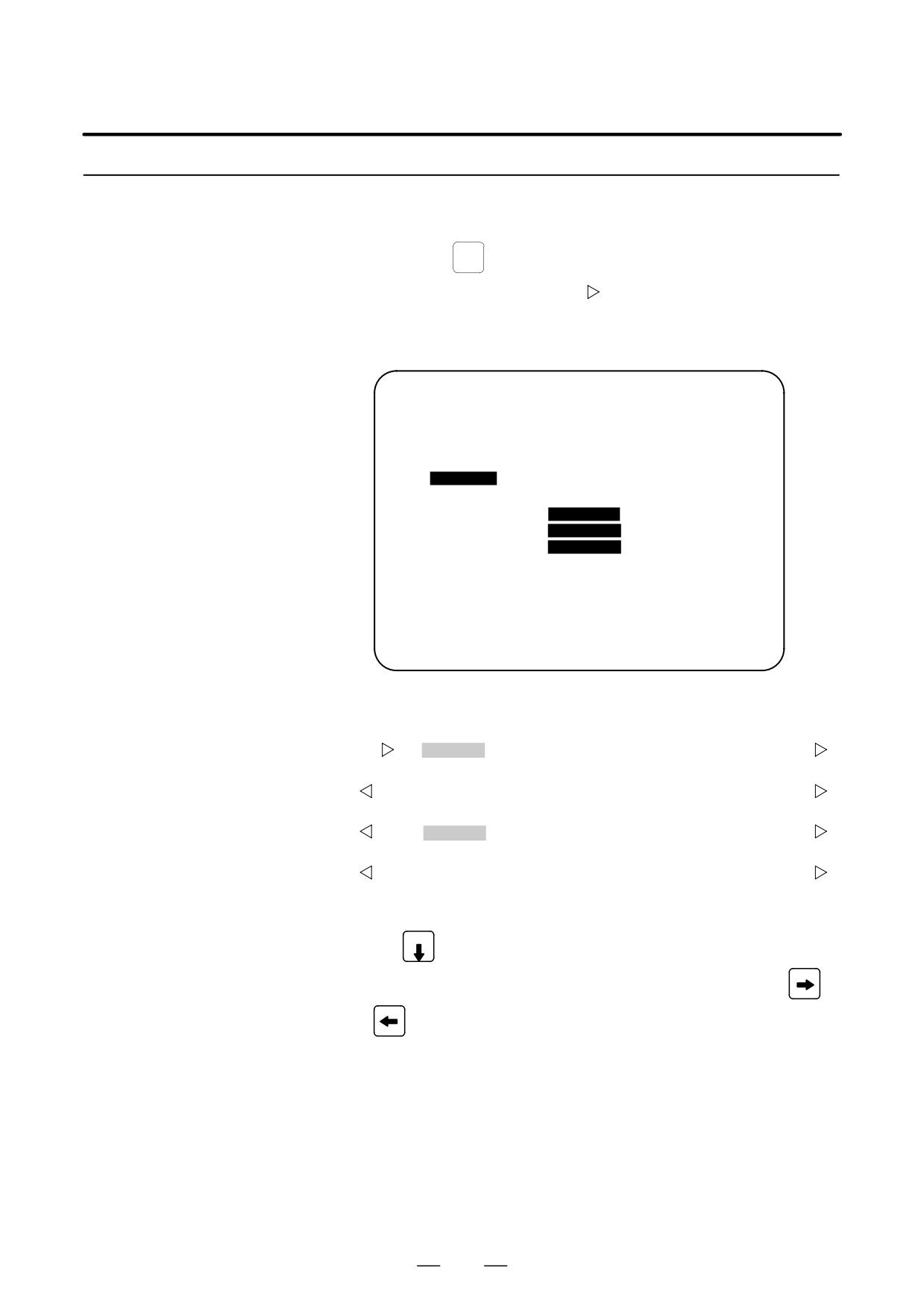
D Displaying the operation
SYSTEM
(1) Press the
function key.
history
(2) Press the continue menu key [
]. The [OPEHIS] (OPERATION
HISTORY) soft key are displayed.
(3) Press the [OPEHIS] soft key twice. The operation history screen is
displayed.
OPERATION HISTORY
O1234 N12345
Page : 123
No. DATA
No. DATA
No. DATA
01 01/06/03
11 F0000.7↑
21 F0001.0↓
02 08:40:00
12 F0000.5↑
22 <POS>
03 <DELETE>
13 F0001.0↑
23 <PROG>
04 F0000.6↑
14 F0000.5↓
24 <RESET>
05 MEM
15 P/S0010
25 EDIT
06 G0009.0↑
16 01/06/03
26 O
07 G0009.1↑
17 09:27:49
27 1
08 G0009.2↑
18 <PROG>
28 2
09 ST↑
19 <RESET>
29 3
10 ST↓
20 F0000.7↓
30 4
EDIT ****
***
***
08:20:52
[ TOP
][ BOTTOM ][
][
][PG.SRH]
On the operation history screen, the soft keys are configured as shown
below:
⇒ [
]
[ PARAM ]
[DGNOS]
[PMC]
[SYSTEM] [(OPE)] [
]
ãpush
[
]
[W.DGNS] [
] [
]
[OPEHIS]
[(OPE)] [
]
ã push
[
]
[ OPEHIS ] [SG-SEL]
[
]
[
]
[(OPE)] [
]
ãpush
[
]
[ TOP
]
[BOTTOM] [
]
[
]
[PG.SRH] [
]
(4) To display the next part of the operation history, press the page down
key PAGE
. The next page is displayed.
To display the interface between two pages, press cursor key
or
. The screen is scrolled by one row. On a 14-inch CRT screen,
pressing the cursor key scrolls the screen by half a page.
These soft keys can also be used:
1) Pressing the [TOP] soft key displays the first page (oldest data).
2) Pressing the [BOTTOM] soft key displays the last page (latest
data).
3) Pressing the [PG.SRH] soft key displays a specified page.
Example) By entering 50 then pressing the [PG.SRH] key, page 50 is
displayed.
43
1. DISPLAY AND OPERATION
B-63525EN/02
Data displayed on the operation history screen
(1) MDI keys
Address and numeric keys are displayed after a single space.
Soft keys are displayed in square brackets ([]).
Other keys (RESET/INPUT, for example) are displayed in angle
brackets (<>).
A key pressed at power-on is displayed in reverse video.
For two-path control, the operations of path 2 are displayed in the
same way, but preceded by S_.
1) Function key: <POS>, <PROG>, <OFFSET>, etc.
2) Address/numeric key: A to Z, 0 to 9, ; (EOB), +, -, (, etc.
3) Page/cursor key: <PAGE↑>, <CUR↓>, <CUR←>
4) Soft key:
[SF1], [SF2], etc.
5) Other key: <RESET>, <CAN>, etc.
6) Key pressed at power-on:
<RESET>
(2) Input and output signals
General signals are displayed in the following format:
G 0 0 0 0 . 7 ↑
The ↑ mark indicates that the signal is
turned on.
The ↓ mark indicates that the signal is
turned off.
Indicates the bit.
Indicates the address.
Some signals are indicated by their symbol names.
SBK ↑ (Indicates that the single block switch is turned on.)
44
B-63525EN/02
1. DISPLAY AND OPERATION
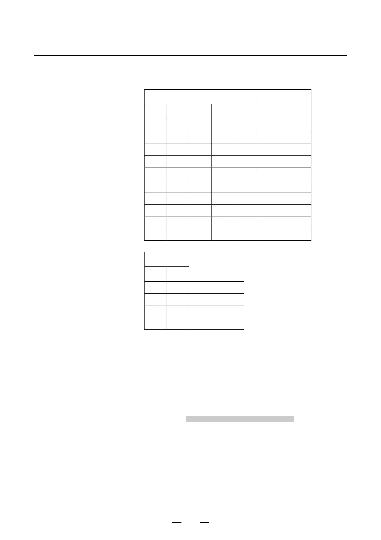
Mode selection signals and rapid traverse override signals
are displayed as indicated below:
Input signal
Name displayed
MD1
ND2
MD4
REF
DNC1
0
0
0
0
0
MDI
1
0
0
0
0
MEM
1
0
0
0
1
RMT
0
1
0
0
0
NOMODE
1
1
0
0
0
EDT
0
0
1
0
0
H/INC
1
0
1
0
0
JOG
1
0
1
1
0
REF
0
1
1
0
0
TJOG
1
1
1
0
0
THND
Input signal
Name displayed
ROV1
ROV2
0
0
R100%
1
0
R50%
0
1
R25%
1
1
RF0%
(3) NC alarms
NC alarms are displayed in reverse video.
P/S alarms, system alarms, and external alarms are displayed together
with their numbers.
For other types of alarms, only the alarm type is displayed. (No details
are displayed.)
For two-path control, the operations of path 2 are displayed in the
same way, but preceded by S_.
Example) P/S0050, SV_ALM, S_APC_ALM
(4) Time stamp (date and time)
The following time data (date and time) is recorded:
1) Date and time of power-on
2) Date and time of power-off
3) Date and time when an NC alarm occurs
4) The clock time is recorded at predetermined intervals, together
with each new calendar day.
45
1. DISPLAY AND OPERATION
B-63525EN/02
1) The power-on time is displayed as shown below:
01/01/20 ==== Year/Month/Day
09:15:30 ==== Hour:Minute:Second
2) The power-off time and the time when an NC alarm occurred are
displayed in reverse video.
01/01/20
====
Year/Month/Day
09:15:30
====
Hour:Minute:Second
If a system alarm occurs, the date and time are not recorded.
3) At predetermined intervals, the clock time is displayed in reverse
video. Set the interval in minutes in parameter No. 3122. If zero
is set, the time is stamped at ten-minute intervals.
09:15:30
====
Hour:Minute:Second
Each new calendar day is displayed in reverse video.
01/01/20
====
Year/Month/Day
CAUTION
1
The clock time is recorded for a specified interval only when
data is stored within that interval.
2
If a system alarm is issued, the system alarm occurrence
time is used for power-off display.
D Input signal or output
(1) P ress the
SYSTEM
function key.
signal to be recorded in
the operation history
(2) Press the continuous menu key [
]. The [OPEHIS] (operation
history) soft key is displayed.
(3) Press the [OPEHIS] soft key, then press the [SG-SEL] soft key. The
operation history signal selection screen is displayed.
OP_HIS SIGNAL SELECT
O1000 N02000
No. ADDRES SIGNAL
No. ADDRES SIGNAL
01
X0000
00001000
11
G0000
00000001
02
X0004
10000000
12
G0004
00000011
03
X0008
00001100
13
G0008
00000111
04
X0009
00111000
14
G0003
00001111
05
X0012
00001111
15
G0043
01100000
06
Y0000
01000000
16
********
07
Y0004
00110000
17
********
08
Y0007
00011100
18
********
09
Y0008
00011100
19
********
10
Y0010
00011100
20
********
>
EDIT
**** *** * * *
00:00:00
[OPEHIS] [SG-SEL] [
] [
] [ (OPE) ]
46
B-63525EN/02
1. DISPLAY AND OPERATION
1.6.3
(1) On the operation history signal selection screen, press the [(OPE)] soft
key.
Setting The Input
Signal or Output Signal
OP_HIS SIGNAL SELECT
O1000 N02000
to Be Recorded in The
No. ADDRES SIGNAL
No. ADDRES SIGNAL
Operation History
01
G0004
00000010
11
********
02
********
12
********
03
********
13
********
04
********
14
********
05
********
15
********
06
********
16
********
07
********
17
********
08
********
18
********
09
********
19
********
10
********
20
********
>
EDIT **** *** *** *** 00:00:00
[ ALLDEL ][ DELETE ][ ON:1 ][ OFF:0 ][
]
(2) Press the cursor key
or
to position the cursor to a desired
position.
(3) Key in a signal type (X, G, F, or Y) and an address, then press the
INPUT
key.
Example) G0004
INPUT
Signal address G0004 is set in the ADDRES column. The corresponding
position in the SIGNAL column is initialized to 000000000.
(4) Select the bit to be recorded.
To select all bits of the specified signal address, press the [ON:1] soft
key while the cursor is positioned to 00000000 .
To select a particular bit, position the cursor to that bit by pressing the
cursor key
or
, then press the [ON:1] soft key. To cancel
a selection made by pressing the [ON:1] soft key or to cancel a
previously selected signal, press the [OFF:0] soft key.
(5) Up to 20 addresses can be specified by means of this signal selection.
These addresses need not always be specified at consecutive positions,
starting from No.1.
(6) Pressing the [ALLDEL] and [EXEC] soft keys deletes all data. If the
[ALLDEL] key is pressed by mistake, it can be cancelled by pressing
the [CAN] key.
(7) To delete a selected signal address, position the cursor to the
corresponding position then press the [DELETE] and [EXEC] soft
keys. In the SIGNAL column, asterisks ******** are displayed in
place of the deleted data. In the ADDRES column, the corresponding
position is cleared.
If the [DELET] key is pressed by mistake, it can be cancelled by
pressing the [CAN] key.
(8) Pressing the return menu key [
] causes the [OPEHIS] (OPE) soft
key to be displayed again.
47
1. DISPLAY AND OPERATION
B-63525EN/02
D Parameter-based setting
By setting bit 4 (PHS) of parameter No. 3206, setting and display on the
operation history signal selection screen can be linked with parameter No.
12801 through No. 12900. By this linking, setting information related to
input and output signals subject to operation history processing can be
input and output in the same way as ordinary parameters.
D Input signals and output
signals to be recorded in
the history
NOTE
1
A cross (×) indicates that a signal will not be recorded. Also,
any signal for which an address is not specified will not be
recorded, either.
2
A circle (f) indicates that a signal can be recorded.
3
A signal indicated by its symbol name will also be displayed
by its symbol name.
1. M/T addresses
MT→PMC
#7
#6
#5
#4
#3
#2
#1
#0
X000
f
f
f
f
f
f
f
f
to
X127
f
f
f
f
f
f
f
f
PMC→CNC
#7
#6
#5
#4
#3
#2
#1
#0
G000
f
f
f
f
f
f
f
f
to
G003
f
f
f
f
f
f
f
f
G004
f
f
f
f
FIN
f
f
f
G005
f
f
f
f
TFIN
SFIN
f
MFIN
G006
f
f
f
f
f
*ABS
f
SRN
G007
RLSOT
EXLM
*FLUP
f
f
ST
STLK
f
G008
ERS
RRW
*SP
*ESP
f
f
f
*IT
G009
f
f
f
f
f
f
f
f
to
G013
f
f
f
f
f
f
f
f
G014
f
f
f
f
f
f
f
f
G015
f
f
f
f
f
f
f
f
to
G018
f
f
f
f
f
f
f
f
G019
RT
f
f
f
f
f
f
f
48
B-63525EN/02
1. DISPLAY AND OPERATION
#7
#6
#5
#4
#3
#2
#1
#0
G020
f
f
f
f
f
f
f
f
to
G042
f
f
f
f
f
f
f
f
G043
f
×
f
×
×
f
f
f
G044
f
f
f
f
f
f
MLK
BDT1
G045
BDT9
BDT8
BDT7
BDT6
BDT5
BDT4
BDT3
BDT2
G046
DRN
KEY4
KEY3
KEY2
KEY1
f
SBK
f
G047
f
f
f
f
f
f
f
f
to
G060
f
f
f
f
f
f
f
f
G061
f
f
f
f
f
f
f
RGTA
G062
f
f
f
f
f
f
f
f
to
G099
f
f
f
f
f
f
f
f
G100
+J8
+J7
+J6
+J5
+J4
+J3
+J2
+J1
G101
f
f
f
f
f
f
f
f
G102
-J8
-J7
-J6
-J5
-J4
-J3
-J2
-J1
G103
f
f
f
f
f
f
f
f
to
G105
f
f
f
f
f
f
f
f
G106
MI8
MI7
MI6
MI5
MI4
MI3
MI2
MI1
G107
f
f
f
f
f
f
f
f
G108
MLK8
MLK7
MLK6
MLK5
MLK4
MLK3
MLK2
MLK1
G109
f
f
f
f
f
f
f
f
G110
+LM8
+LM7
+LM6
+LM5
+LM4
+LM3
+LM2
+LM1
G111
f
f
f
f
f
f
f
f
G112
-LM8
–LM7
-LM6
-LM5
-LM4
-LM3
-LM2
-LM1
G113
f
f
f
f
f
f
f
f
G114
*+L8
*+L7
*+L6
*+L5
*+L4
*+L3
*+L2
*+L1
49
1. DISPLAY AND OPERATION
B-63525EN/02
#7
#6
#5
#4
#3
#2
#1
#0
G115
f
f
f
f
f
f
f
f
G116
*-L8
*-L7
*-L6
*-L5
*-L4
*-L3
*-L2
*-L1
G117
f
f
f
f
f
f
f
f
G118
*+ED8
*+ED7
*+ED6
*+ED5
*+ED4
*+ED3
*+ED2
*+ED1
G119
f
f
f
f
f
f
f
f
G120
*-ED8
*-ED7
*-ED6
*-ED5
*-ED4
*-ED3
*-ED2
*-ED1
G121
f
f
f
f
f
f
f
f
to
G125
f
f
f
f
f
f
f
f
G126
SVF8
SVF7
SVF6
SVF5
SVF4
SVF3
SVF2
SVF1
G127
f
f
f
f
f
f
f
f
to
G129
f
f
f
f
f
f
f
f
G130
*IT8
*IT7
*IT6
*IT5
*IT4
*IT3
*IT2
*IT1
G131
f
f
f
f
f
f
f
f
G132
f
f
f
f
+MIT4
+MIT3
+MIT2
+MIT1
G133
f
f
f
f
f
f
f
f
G134
f
f
f
f
-MIT4
-MIT3
-MIT2
-MIT1
G135
f
f
f
f
f
f
f
f
to
G255
f
f
f
f
f
f
f
f
PMC→MT
#7
#6
#5
#4
#3
#2
#1
#0
Y000
f
f
f
f
f
f
f
f
to
Y127
f
f
f
f
f
f
f
f
CNC→PMC
#7
#6
#5
#4
#3
#2
#1
#0
F000
f
f
f
f
f
f
f
f
to
F255
f
f
f
f
f
f
f
f
50
B-63525EN/02
1. DISPLAY AND OPERATION
2. List of Address for 2-path control
MT→PMC
#7
#6
#5
#4
#3
#2
#1
#0
X000
f
f
f
f
f
f
f
f
to
X127
f
f
f
f
f
f
f
f
PMC→CNC (Signals for tool post 1)
#7
#6
#5
#4
#3
#2
#1
#0
G000
f
f
f
f
f
f
f
f
to
G003
f
f
f
f
f
f
f
f
G004
f
f
f
f
FIN
f
f
f
G005
f
f
f
f
TFIN
SFIN
f
MFIN
G006
f
f
f
f
f
*ABS
f
SRN
G007
RLSOT
EXLM
*FLUP
f
f
ST
STLK
f
G008
ERS
RRW
*SP
*ESP
f
f
f
*IT
G009
f
f
f
f
f
f
f
f
to
G013
f
f
f
f
f
f
f
f
G014
f
f
f
f
f
f
f
f
G015
f
f
f
f
f
f
f
f
to
G018
f
f
f
f
f
f
f
f
G019
RT
f
f
f
f
f
f
f
G020
f
f
f
f
f
f
f
f
to
G042
f
f
f
f
f
f
f
f
G043
f
×
f
×
×
f
f
f
G044
f
f
f
f
f
f
MLK
BDT1
G045
BDT9
BDT8
BDT7
BDT6
BDT5
BDT4
BDT3
BDT2
G046
DRN
KEY4
KEY3
KEY2
KEY1
f
SBK
f
G047
f
f
f
f
f
f
f
f
to
G060
f
f
f
f
f
f
f
f
51
1. DISPLAY AND OPERATION
B-63525EN/02
#7
#6
#5
#4
#3
#2
#1
#0
G061
f
f
f
f
f
f
f
RGTA
G062
f
f
f
f
f
f
f
f
to
G099
f
f
f
f
f
f
f
f
G100
+J8
+J7
+J6
+J5
+J4
+J3
+J2
+J1
G101
f
f
f
f
f
f
f
f
G102
–J8
-J7
-J6
-J5
-J4
-J3
-J2
-J1
G103
f
f
f
f
f
f
f
f
to
G105
f
f
f
f
f
f
f
f
G106
MI8
MI7
MI6
MI5
MI4
MI3
MI2
SMI1
G107
f
f
f
f
f
f
f
f
G108
MLK8
MLK7
MLK6
MLK5
MLK4
MLK3
MLK2
MLK1
G109
f
f
f
f
f
f
f
f
G110
+LM8
+LM7
+LM6
+LM5
+LM4
+LM3
+LM2
+LM1
G111
f
f
f
f
f
f
f
f
G112
-LM8
–LM7
-LM6
-LM5
-LM4
-LM3
-LM2
-LM1
G113
f
f
f
f
f
f
f
f
G114
*+L8
*+L7
*+L6
*+L5
*+L4
*+L3
*+L2
*+L1
G115
f
f
f
f
f
f
f
f
G116
*-L8
*-L7
*-L6
*-L5
*-L4
*-L3
*-L2
*-L1
G117
f
f
f
f
f
f
f
f
G118
*+ED8
*+ED7
*+ED6
*+ED5
*+ED4
*+ED3
*+ED2
*+ED1
G119
f
f
f
f
f
f
f
f
G120
*-ED8
*-ED7
*-ED6
*-ED5
*-ED4
*-ED3
*-ED2
*-ED1
G121
f
f
f
f
f
f
f
f
to
G125
f
f
f
f
f
f
f
f
52
B-63525EN/02
1. DISPLAY AND OPERATION
#7
#6
#5
#4
#3
#2
#1
#0
G126
SVF8
SVF7
SVF6
SVF5
SVF4
SVF3
SVF2
SVF1
G127
f
f
f
f
f
f
f
f
to
G129
f
f
f
f
f
f
f
f
G130
*IT8
*IT7
*IT6
*IT5
*IT4
*IT3
*IT2
*IT1
G131
f
f
f
f
f
f
f
f
G132
f
f
f
f
+MIT4
+MIT3
+MIT2
+MIT1
G133
f
f
f
f
f
f
f
f
G134
f
f
f
f
-MIT4
-MIT3
-MIT2
-MIT1
G135
f
f
f
f
f
f
f
f
to
G255
f
f
f
f
f
f
f
f
PMC→CNC (Signals for the 2-path)
#7
#6
#5
#4
#3
#2
#1
#0
G1000
f
f
f
f
f
f
f
f
to
G1003
f
f
f
f
f
f
f
f
G1004
f
f
f
f
FIN
f
f
f
G1005
f
f
f
f
TFIN
SFIN
f
MFIN
G1006
f
f
f
f
f
*ABS
f
SRN
G1007
RLSOT
EXLM
*FLUP
f
f
ST
STLK
f
G1008
ERS
RRW
*SP
*ESP
f
f
f
*IT
G1009
f
f
f
f
f
f
f
f
to
G1013
f
f
f
f
f
f
f
f
G1014
f
f
f
f
f
f
f
f
G1015
f
f
f
f
f
f
f
f
to
G1018
f
f
f
f
f
f
f
f
G1019
RT
f
f
f
f
f
f
f
53
1. DISPLAY AND OPERATION
B-63525EN/02
#7
#6
#5
#4
#3
#2
#1
#0
G1020
f
f
f
f
f
f
f
f
to
G1042
f
f
f
f
f
f
f
f
G1043
f
×
f
×
×
f
f
f
G1044
f
f
f
f
f
f
MLK
BDT1
G1045
BDT9
BDT8
BDT7
BDT6
BDT5
BDT4
BDT3
BDT2
G1046
DRN
KEY4
KEY3
KEY2
KEY1
f
SBK
f
G1047
f
f
f
f
f
f
f
f
to
G1060
f
f
f
f
f
f
f
f
G1061
f
f
f
f
f
f
f
RGTA
G1062
f
f
f
f
f
f
f
f
to
G1099
f
f
f
f
f
f
f
f
G1100
+J8
+J7
+J6
+J5
+J4
+J3
+J2
+J1
G1101
f
f
f
f
f
f
f
f
G1102
-J8
–J7
-J6
-J5
-J4
-J3
-J2
-J1
G1103
f
f
f
f
f
f
f
f
to
G1105
f
f
f
f
f
f
f
f
G1106
MI8
MI7
MI6
MI5
MI4
MI3
MI2
SMI1
G1107
f
f
f
f
f
f
f
f
G1108
MLK8
MLK7
MLK6
MLK5
MLK4
MLK3
MLK2
MLK1
G1109
f
f
f
f
f
f
f
f
G1110
+LM8
+LM7
+LM6
+LM5
+LM4
+LM3
+LM2
+LM1
G1111
f
f
f
f
f
f
f
f
G1112
-LM8
–LM7
-LM6
-LM5
-LM4
-LM3
-LM2
-LM1
G1113
f
f
f
f
f
f
f
f
G1114
*+L8
*+L7
*+L6
*+L5
*+L4
*+L3
*+L2
*+L1
G1115
f
f
f
f
f
f
f
f
54
B-63525EN/02
1. DISPLAY AND OPERATION
#7
#6
#5
#4
#3
#2
#1
#0
G1116
*-L8
*-L7
*-L6
*-L5
*-L4
*-L3
*-L2
*-L1
G1117
f
f
f
f
f
f
f
f
G1118
*+ED8
*+ED7
*+ED6
*+ED5
*+ED4
*+ED3
*+ED2
*+ED1
G1119
f
f
f
f
f
f
f
f
G1120
*-ED8
*-ED7
*-ED6
*-ED5
*-ED4
*-ED3
*-ED2
*-ED1
G1121
f
f
f
f
f
f
f
f
to
G1125
f
f
f
f
f
f
f
f
G1126
SVF8
SVF7
SVF6
SVF5
SVF4
SVF3
SVF2
SVF1
G1127
f
f
f
f
f
f
f
f
to
G1129
f
f
f
f
f
f
f
f
G1130
*IT8
*IT7
*IT6
*IT5
*IT4
*IT3
*IT2
*IT1
G1131
f
f
f
f
f
f
f
f
G1132
f
f
f
f
+MIT4
+MIT3
+MIT2
+MIT1
G1133
f
f
f
f
f
f
f
f
G1134
f
f
f
f
-MIT4
-MIT3
-MIT2
-MIT1
G1135
f
f
f
f
f
f
f
f
to
G1255
f
f
f
f
f
f
f
f
PMC→MT
#7
#6
#5
#4
#3
#2
#1
#0
Y000
f
f
f
f
f
f
f
f
to
Y127
f
f
f
f
f
f
f
f
CNC→PMC (Signals for the 1-path)
#7
#6
#5
#4
#3
#2
#1
#0
F000
f
f
f
f
f
f
f
f
to
F255
f
f
f
f
f
f
f
f
CNC→PMC (Signals for the 2-path)
#7
#6
#5
#4
#3
#2
#1
#0
F1000
f
f
f
f
f
f
f
f
to
F1255
f
f
f
f
f
f
f
f
55
1. DISPLAY AND OPERATION
B-63525EN/02
1.6.4
Recorded data can be output to an input/output unit connected via a
reader/punch interface. An output record can be input from the
Inputting and
input/output unit.
Outputting the
Set the input/output unit to be used in setting parameters No. 0020 and
Operation History Data
0100 to 0135.
To output the data, set a code in the ISO bit of a setting parameter (bit 1
of parameter No. 0020).
D Output
(1) Select EDIT mode.
(2) Press the
SYSTEM
key, then select the operation history display screen.
(3) Press the soft keys [(OPRT)],
, [PUNCH], and [EXEC] in this
order.
The data output to the FANUC Floppy Cassette or FANUC FA Card is
stored under file name OPERATION HISTORY.
D Input
(1) Select EDIT mode.
(2) Press the
SYSTEM
key, then select the operation history display screen.
(3) Press the soft keys [(OPRT)],
, [READ], and [EXEC] in this
order.
D Output data format
1. MDI/soft key
2. Signal
3. Alarm
4. For extension (date or time)
5. MDI/soft key of path 2
6. Signal of path 2
7. Alarm of path 2
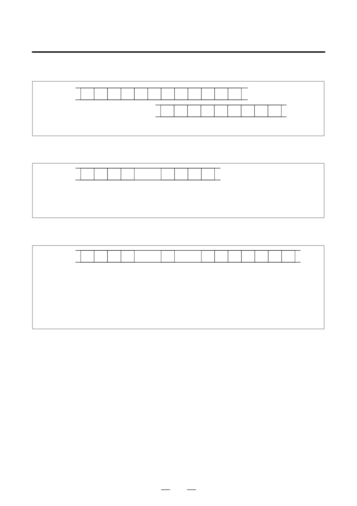
The header and recorded operation data are output, in this order. The
operation history data is divided into four parts by identifier words. Data
other than the identifier words depends on the type.
T(identifier word)
T0
: Header
T50
: MDI/soft key
T51
: Signal
T52
: Alarm
T53
: For extension (date or time)
T54
: MDI/soft key of path 2
T55
: Signal of path 2
T56
: Alarm of path 2
56
B-63525EN/02
1. DISPLAY AND OPERATION
1) Header
T
0
C
O
P
E
R
A
T
I
O
N
H
I
S
T
O
R
Y
;
C: Data word
2) MDI/soft key
T
5
0
P
0 to 1
H
*
;
P0: Usually
P1: At power-on
H **:
Key code (See the following table.)
3) Signal
T
5
1
P
0
to 6
N
0 to 255
H
*
*
,
*
;
New data Old data
P0: X0000 and above
P2: G0000 and above
P4: Y0000 and above
P6: F0000 and above
N***: DI/DO number
H **: Signal information data (hexadecimal)
57
1. DISPLAY AND OPERATION
B-63525EN/02
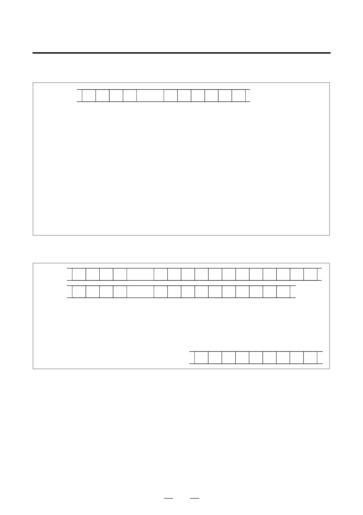
4) Alarm
T
5
2
P
0 to 10
N
*
;
P0: P/S No. 100
P1: P/S No. 000
P2: P/S No. 101
P3: P/S No. 0001 to 254
P4: Overtravel alarm
P5: Overheat alarm
P6: Servo alarm
P7: System alarm
P8: APC alarm
P9: Spindle alarm
P10: P/S alarm No. 5000 to 5999
P15: External alarm
N****: Alarm number (for P/S alarm, system alarm, and external
alarm only)
5) For extension (date or time)
Date
T
5
3
P
0 to 1
E
0
D
;
Time
T
5
3
P
0 to 1
E
1
D
;
P0: Usually
P1: At power-on
E0: Date
E1: Time
D*..*: Data Example) June 29, 2001
D
2
0
0
1
0
6
2
9
58
B-63525EN/02
1. DISPLAY AND OPERATION
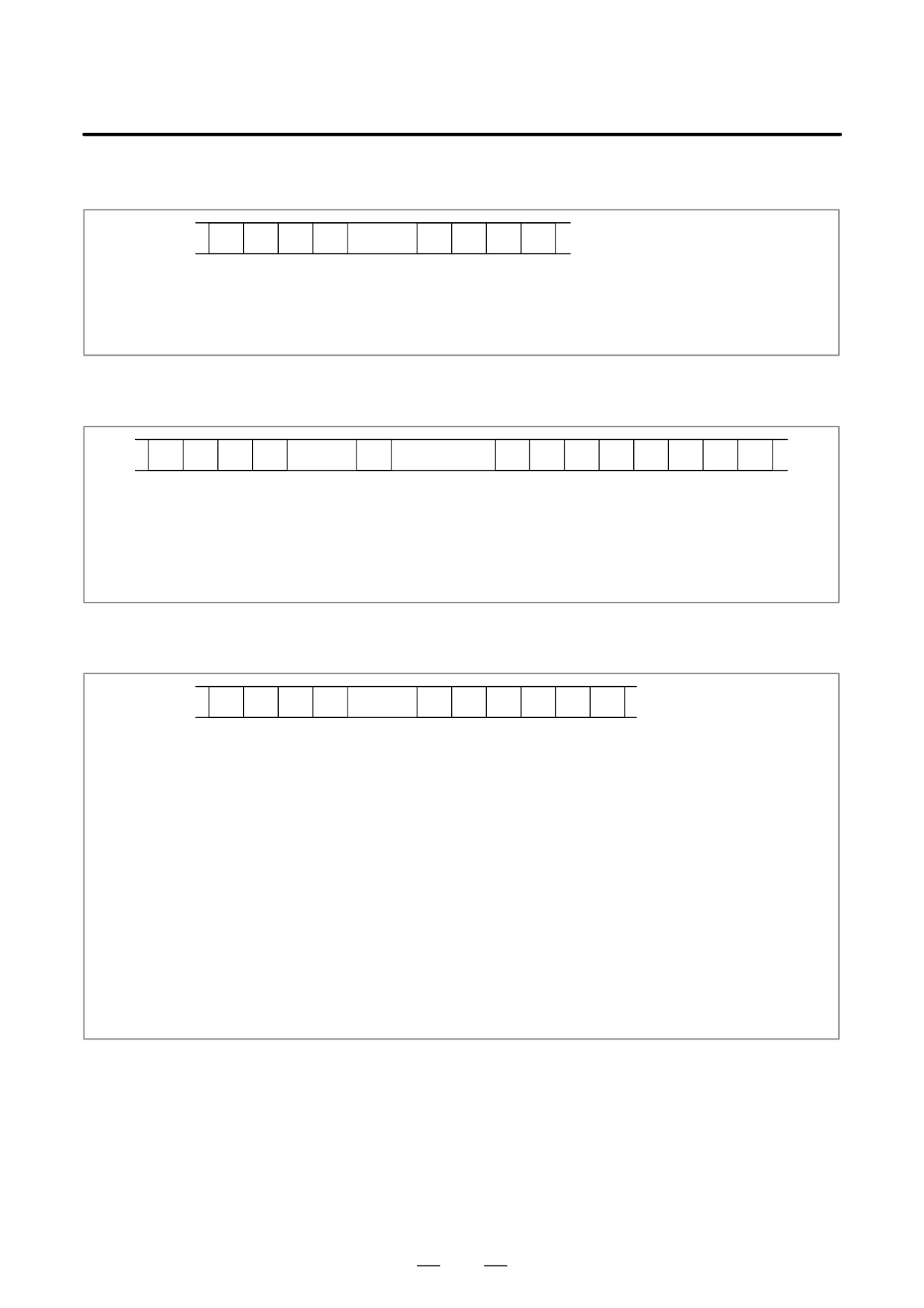
6) MDI/soft key of path 2
T
5
4
P
0 to 1
H
;
P0: Usually
P1: At power-on
H **:
KCB code (See the following table.)
7) Signal of path 2
T
5
5
P
2, 6
N
1000
to 1255
H
*
,
*
*
;
New data Old data
P2: G1000 and above
P6: F1000 and above
N***:
DI/DO number
H **:
Signal information data (hexadecimal)
8) Alarm of path 2
T
5
6
P
0 to 10
N
*
;
P0: P/S No. 100
P1: P/S No. 000
P2: P/S No. 101
P3: P/S No. 001 to 254
P4: Overtravel alarm
P5: Overheat alarm
P6: Servo alarm
P7: System alarm
P8: APC alarm
P9: Spindle alarm
P10: P/S alarm No. 5000 to 5999
P15: External alarm
N****: Alarm number (for P/S alarm, system alarm, and external
alarm only)
59
1. DISPLAY AND OPERATION
B-63525EN/02
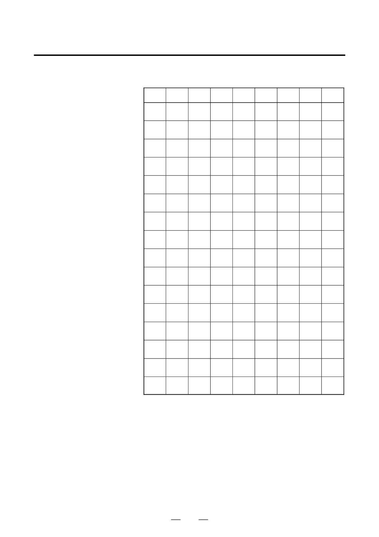
Key codes (MDI/soft key)
(00H to 7FH)
0
1
2
3
4
5
6
7
0
Space
0
@
P
1
!
1
A
Q
2
”
2
B
R
3
#
3
C
S
4
$
4
D
T
5
%
5
E
U
6
&
6
F
V
7
’
7
G
W
8
(
8
H
X
9
)
9
I
Y
A
;
:
J
Z
(EOB)
B
+
K
[
C
’
<
L
¥
D
-
=
M
]
E
>
N
F
/
?
O
-
60
B-63525EN/02
1. DISPLAY AND OPERATION
(80H to FFH)
8
9
A
B
C
D
E
F
0
Reset
F0
1
MMC
F1
2
CNC
F2
3
F3
4
Shift
Insert
F4
5
Delete
F5
6
CAN
Alter
F6
7
F7
8
Cur→
Input
POS
F8
9
Cur←
PROG
F9
A
Cur↓
Help
OFFSET
SETTING
B
Cur↑
SYSTEM
C
MESSAGE
D
CUSTOM
GRAPH
*1*
E
Page↓
CUSTOM
FR
F
Page↑
Fapt
FL
CUSTOM
*1:On the small-sized keypad, ED corresponds to the
GRAPH
key. On a
standard keyboard, ED corresponds to the
GRAPH
key and EE to the
CUSTOM
key.
* : Command key
61