FANUC Series 16i/160i/160is-MODEL B, Series 18i/180i/180is-MODEL B, Series 21i/210i/210is-MODEL B. MAINTENANCE MANAUL - page 4
1. DISPLAY AND OPERATION
B-63525EN/02
1.6.5
(1) While the operation history screen is displayed, no information can be
recorded to the history.
Notes
(2) An input signal having an on/off width of up to 16 msec is not recorded
in the history. Some signals are not recorded in the history.
(3) Once the storage becomes full, old data is deleted, starting from the
oldest record. Up to about 8000 key information items can be
recorded.
(4) The recorded data is retained even after the power is turned off. A
memory all clear operation, however, erases the recorded data.
(5) The operation history function cannot execute sampling when the
OHS bit (bit 7 of parameter No. 3106) is set to 1.
(6) Set the date and time on the setting screen.
(7) The time needed to input and output 6000 operation records at a rate
of 4800 baud is as follows:
Output:About 5 minutes
Input: About 2 minutes and 30 seconds
This file corresponds to a paper tape of about 180 m in length.
62
B-63525EN/02
1. DISPLAY AND OPERATION
1.7
HELP FUNCTION
The help function displays alarm information, operation method and a
1.7.1
table of contents for parameters. This function is used as a handbook.
General
1.7.2
Press
HELP
key on any screen other than PMC screen, then a help screen
Display Method
appears.
(However, it is not available when PMC screen/CUSTOM screen is
displaying)
D Display of help screen
HELP (INITIAL MENU)
O1234 N12345
*****
HELP
*****
1. ALARM DETAIL
2. OPERATION METHOD
3. PARAMETER TABLE
[ALARM]
[OPERAT]
[PARAM]
[
]
[
]
D Help for alarm
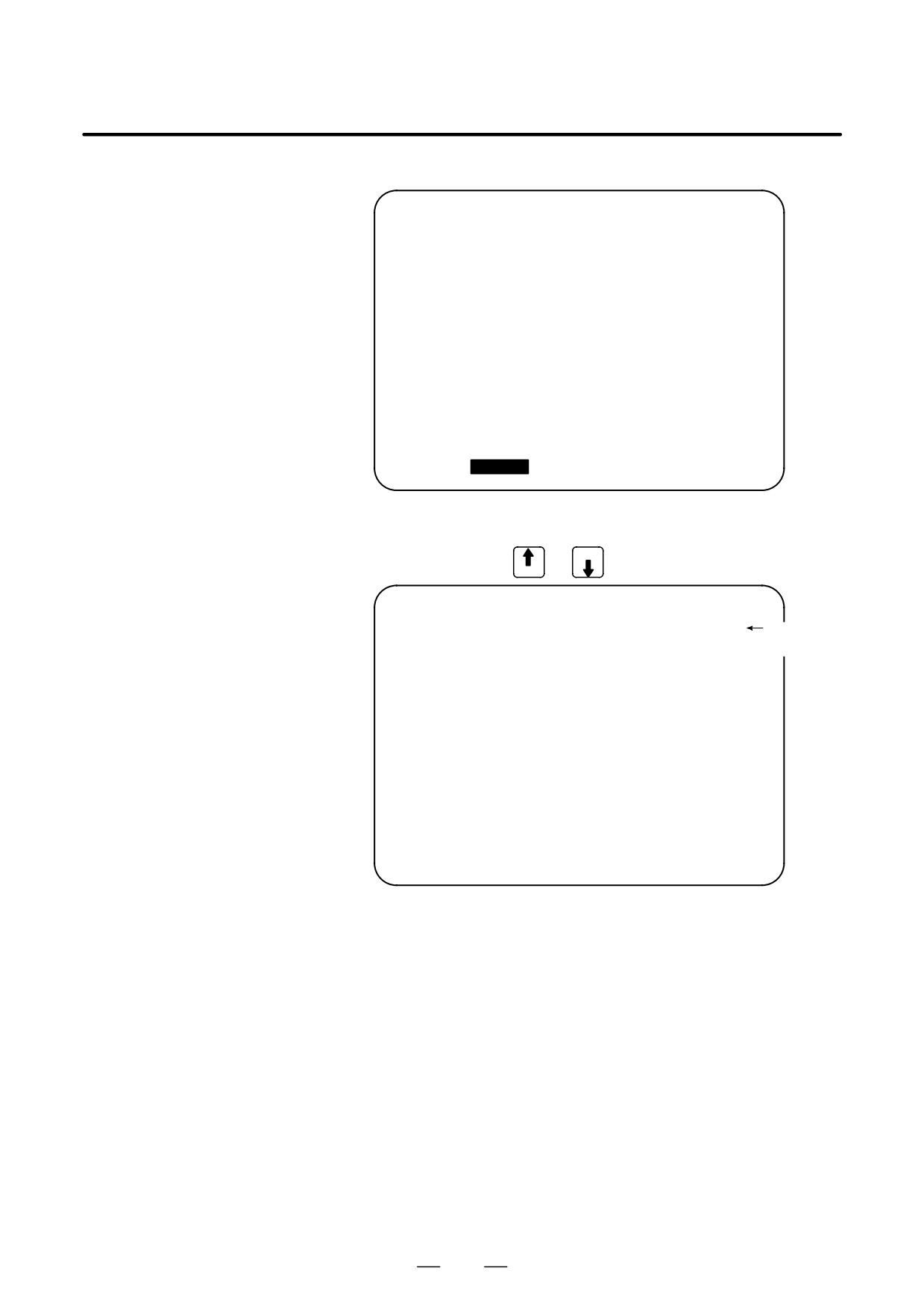
(1) When an alarm is generated, press soft key [ALARM], then a help
message of the alarm is displayed.
HELP (INITIAL MENU)
O1234 N12345
NUMBER
: 010
M’SAGE
: IMPROPER G CODE
FUNCTION
:
ALARM
:
A G CODE NOT LISTED IN G-CODE TABLE
IS BEING COMMANDED
ALSO G-CODE FOR FUNCTION NOT ADDED
IS BEING COMMANDED
[ALARM]
[OPERAT]
[PARAM] [
] [ (OPRT) ]
(2) Pressing soft key [OPERAT],(alarm No.), and soft key [SELECT]
in this order, a help message corresponding to the input alarm number
is displayed.
63
1. DISPLAY AND OPERATION
B-63525EN/02
D Help for operation
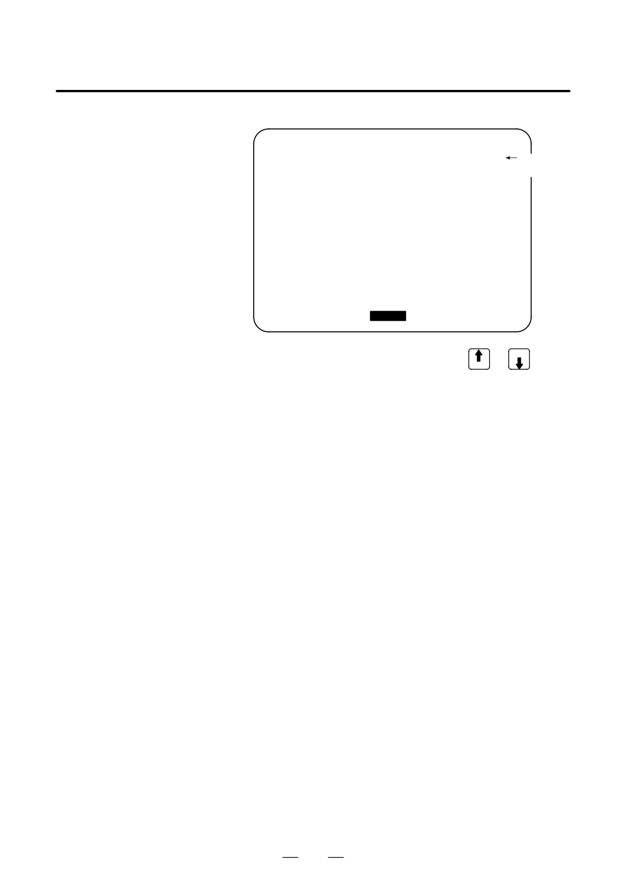
(1) Press [2 OPR], then a menu for operation method is displayed.
HELP (OPERATION METHOD)
O1234 N12345
1. PROGRAM EDIT
2. SEARCH
3. RESET
4. DATA INPUT WITH MDI
5. DATA INPUT WITH TAPE
6. OUTPUT
7. INPUT WITH FANUC CASSETTE
8. OUTPUT WITH FANUC CASSETTE
9. MEMORY CLEAR
[ALARM]
[OPRERAT]
[PARAM] [
]
[(OPRT)]
(2) Press [OPERAT], (an item number) and soft key [SELECT], then an
operation method of the item is displayed.
PAGE
Pressing PAGE key
or
displays another pages.
PAGE
HELP (OPERATION METHOD)
O1234 N12345
<<1.PROGRAM EDIT>>
1/4
Current
page/ Total
DELETE ALL PROGRAMS
page
MODE :EDIT
SCREEN :PROGRAM
OPR
:(0-9999) - (DELETE)
DELETE ONE PROGRAM
MODE : EDIT
SCREEN : PROGRAM
OPR
:(0+PROGRAM NUMBER) - <DELETE>
[
]
[
]
[
]
[
]
[SELECT]
64
B-63525EN/02
1. DISPLAY AND OPERATION
D Parameter table
Press soft key [PARAM], then a parameter table is displayed.
HELP (PARAMETER TABLE)
O1234 N12345
1/4
Current
page/ Total
·SETTING
(NO.0000~ )
page
·READER/PUNCHER INTERFACE
(NO.0100~ )
·AXIS CONTROL/SETTING UNIT
(NO.1000~ )
·COORDINATE SYSTEM
(NO.1200~ )
·STROKE LIMIT
(NO.1300~ )
·FEED RATE
(NO.1400~ )
·ACCEL/DECELERATION CTRL
(NO.1600~ )
·SERVO RELATED
(NO.1800~ )
·DI/DO
(NO.3000~ )
[ ALARM ] [OPERAT][
PARAM
] [
][SELECT]
PAGE
Another screen can be selected by the PAGE key
or
PAGE
65

1. DISPLAY AND OPERATION
B-63525EN/02
1.8
DISPLAYING
DIAGNOSTIC PAGE
1.8.1
(1) Press
SYSTEM
key.
Displaying Diagnostic
(2) Press soft key [DGNOS], then a diagnostic screen is displayed.
Page
1.8.2
Contents Displayed
D Causes when the
000 WAITING FOR FIN SIGNAL
An auxiliary function is being
machine does not travel
executed.
in spite of giving a
001 MOTION
Travel command of cycle
command
operation is being executed.
002 DWELL
DWELL Dwell is being executed.
003 IN-POSITION CHECK
In-position check is being done.
004 FEEDRATE OVERRIDE 0%
Feedrate override is 0%.
005 INTERLOCK/START LOCK
Interlock or start lock is input.
006 SPINDLE SPEED ARRIVAL CHECK
Waiting for spindle speed
arrival signal.
010 PUNCHING
Data is being output through
reader/puncher interface.
011 READING
Data is being input through
reader/puncher interface.
012 WAITING FOR (UN) CLAMP
Waiting for the end of index
table indexing
013 JOG FEEDRATE OVERRIDE 0%
Manual feedrate override is 0%.
014 WAITING FOR RESET, ESP,RRW OFF
NC is in reset state.
015 EXTERNAL PROGRAM NUMBER SEARCH
External Program Number
Search External program
number search is being done
016 BACKGROUND ACTIVE
Background is being used.
66
B-63525EN/02
1. DISPLAY AND OPERATION
D Cause of the cycle start
LED turned off
020 CUT SPEED UP/DOWN
1
0
0
0
1
0
0
021 RESET BUTTON ON
0
0
1
0
0
0
0
022 RESET AND REWIND ON
0
0
0
1
0
0
0
023 EMERGENCY STOP ON
1
0
0
0
0
0
0
024 RESET ON
1
1
1
1
0
0
0
025 STOP MOTION OR DWELL
1
1
1
1
1
1
0
Input of emergency stop signal
Input of external reset signal
Reset button On of MDI
Input of reset & rewind
Servo alarm generation
Switching to other mode, Feed hold
Single block stop
D State of TH alarm
030 CHARACTER NUMBER TH ALARM Position of the character that
caused TH alarm. The position
is counted from the head.
031 TH DATA
Data of the character that caused
TH alarm.
D Screen hard copy status
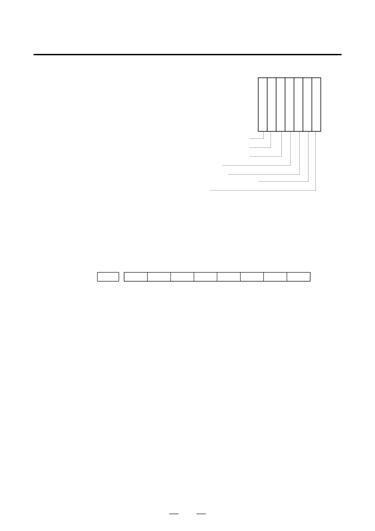
#7
#6
#5
#4
#3
#2
#1
#0
DGN
035
ER3
ER2
ER1
ABT
END
END:
Screen hard copy was completed normally.
ABT:
Screen hard copy was discontinued.
ER1:
An invalid parameter value was specified for screen hard copy.
ER2:
An attempt to use a memory card for screen hard copy failed.
ER3:
An error occurred during writing to a memory card for screen hard copy.
67
1. DISPLAY AND OPERATION
B-63525EN/02
D C executor status
DGN
045
C executor status
[Data type]
Byte
[Valid data range]
0 to 255
C executor status
0:
Normal.
2:
Inoperable because of an incorrect FROM content.
3:
Inoperable because the power was switched on with the M and 0 keys held
down.
5:
Inoperable because of insufficient SRAM area; increase the SRAM area size.
Alternatively, inoperable because of an incorrect C executor library version; use
a new C executor library.
6:
Inoperable because of an internal error.
7:
Inoperable because of an internal error.
9:
Inoperable because of an internal error.
10:
Inoperable because of an incorrect C executor library version; use a new C
executor library.
11:
Inoperable because of an incorrect FROM content.
12:
Inoperable because of an internal error.
D Details of serial pulse
coder
#7
#6
#5
#4
#3
#2
#1
#0
DGN
200
OVL
LV
OVC
HCA
HVA
DCA
FBA
OFA
#7(OVL): Overload alarm
#6(LV): Insufficient voltage alarm
#5(OVC): Over current alarm
#4(HCA): Abnormal current alarm
#3(HVA): Overvoltage alarm
#2(DCA): Discharge alarm
#1(FBA): Disconnection alarm
#0(OFA): Overflow alarm
68
B-63525EN/02
1. DISPLAY AND OPERATION
#7
#6
#5
#4
#3
#2
#1
#0
DGN
201
ALD
EXP
Overload
1
-
-
-
Motor overheat
alarm
0
-
-
-
Amplifier overheat
Disconnec-
1
-
-
0
Built-in pulse coder (hand)
tion alarm
1
-
-
1
Disconnection of separated type pulse
coder (hard)
0
-
-
0
Disconnection of pulse coder (software)
#7
#6
#5
#4
#3
#2
#1
#0
DGN
202
CSA
BLA
PHA
RCA
BZA
CKA
SPH
#6(CSA):
Hardware of serial pulse coder is abnormal
#5(BLA):
Battery voltage is low (warning)
#4(PHA):
Serial pulse coder or feedback cable is erroneous.
#3(RCA):
Serial pulse coder is faulty.
Counting of feedback cable is erroneous.
#2(BZA):
Battery voltage became 0.
Replace the battery and set the reference position.
#1(CKA):
Serial pulse coder is faulty.
Internal block stopped.
#0(SPH):
Serial pulse coder or feedback cable is faulty.
Counting of feedback cable is erroneous.
#7
#6
#5
#4
#3
#2
#1
#0
DGN
203
DTE
CRC
STB
PRM
#7(DTE): Communication failure of serial pulse coder.
There is no response for communication.
#6(CRC): Communication failure of serial pulse coder.
Transferred data is erroneous.
#5(STB): Communication failure of serial pulse coder.
Transferred data is erroneous.
#4(PRM): The alarm is detected by the servo, the values specified in the parameter is
not correct.
#7
#6
#5
#4
#3
#2
#1
#0
DGN
204
OFS
MCC
LDA
PMS
#6(OFS): Abnormal current value result of A/D conversion of digital
#5(MCC): Contacts of MCC of servo amplifier is melted.
#4(LDA): Serial pulse coder LED is abnormal
#3(PMS): Feedback is not correct due to faulty serial pulse coder C or feedback
cable.
69
1. DISPLAY AND OPERATION
B-63525EN/02
D Details of separate serial
pulse coder alarms
#7
#6
#5
#4
#3
#2
#1
#0
DGN
205
OHA
LDA
BLA
PHA
CMA
BZA
PMA
SPH
#7(OHA): Overheat occurred in the separate pulse coder.
#6(LDA): An LED error occurred in the separate pulse coder.
#5(BLA): A low battery voltage occurred in the separate pulse coder.
#4(PHA): A phase data error occurred in the separate linear scale.
#3(CMA): A count error occurred in the separate pulse coder.
#2(BZA): The battery voltage for the separate pulse coder is zero.
#1(PMA): A pulse error occurred in the separate pulse coder.
#0(SPH): A soft phase data error occurred in the separate pulse coder.
#7
#6
#5
#4
#3
#2
#1
#0
DGN
206
DTE
CRC
STB
#7(DTE):
A data error occurred in the separate pulse coder.
#6(CRC):
A CRC error occurred in the separate pulse coder.
#5(STB):
A stop bit error occurred in the separate pulse coder.
D Details of invalid servo
This data indicates the cause of servo alarm No. 417, detected by the NC.
parameter alarms (on the
If the alarm is detected by the servo, the PRM bit (bit 4 of DGN No. 0203)
CNC side)
is set to 1.
#7
#6
#5
#4
#3
#2
#1
#0
DGN
280
AXS
DIR
PLS
PLC
MOT
#0(MOT):
The motor type specified in parameter No. 2020 falls outside the
predetermined range.
#2(PLC):
The number of velocity feedback pulses per motor revolution, specified in
parameter No. 2023, is zero or less. The value is invalid.
#3(PLS):
The number of position feedback pulses per motor revolution, specified in
parameter No. 2024, is zero or less. The value is invalid.
#4(DIR):
The wrong direction of rotation for the motor is specified in parameter No.
2022 (the value is other than 111 or -111).
#6(AXS):
In parameter No. 1023 (servo axis number), a value that falls outside the
range of 1 to the number of controlled axes is specified. (For example, 4 is
specified instead of
3.)
Alternatively, the values specified in the
parameter are not consecutive.
D Position error amount
DGN
300
Position error of an axis in detection unit
Feed rate [mm/min]
1
Position error=
×
60 servo loop gain [1/sec]
Detection unit
D Machine position
DGN
301
Distance from reference position of an axis in detection unit
70
B-63525EN/02
1. DISPLAY AND OPERATION
D Reference position shift
function
DGN
302
Distance from the end of the deceleration dog to the first grid point
[Data type]
Two-word axis
[Units of data]
0.001 mm (metric output), 0.0001 inch (inch output)
[Valid data range]
-99999999 to 99999999
D Position deviation with
fine acceleration/
deceleration enabled
DGN
303
Position deviation with fine acceleration/deceleration enabled
[Data type]
Two-word axis
[Unit of data]
Detection unit
[Valid data range]
-99999999 to 99999999
D Reference counter
DGN
304
Reference counter for individual axes
[Data type]
Two-word axis
[Unit of data]
Detection unit
[Valid data range]
-99999999 to 99999999
D Displacement detection
DGN
305
Position feedback data between Z phases of individual axes
[Data type]
Two-word axis
[Unit of data]
Detection unit
[Valid data range]
-99999999 to 99999999
If displacement detection is enabled, the feedback data between the Z
phases of different axes is represented in the detection unit.
71
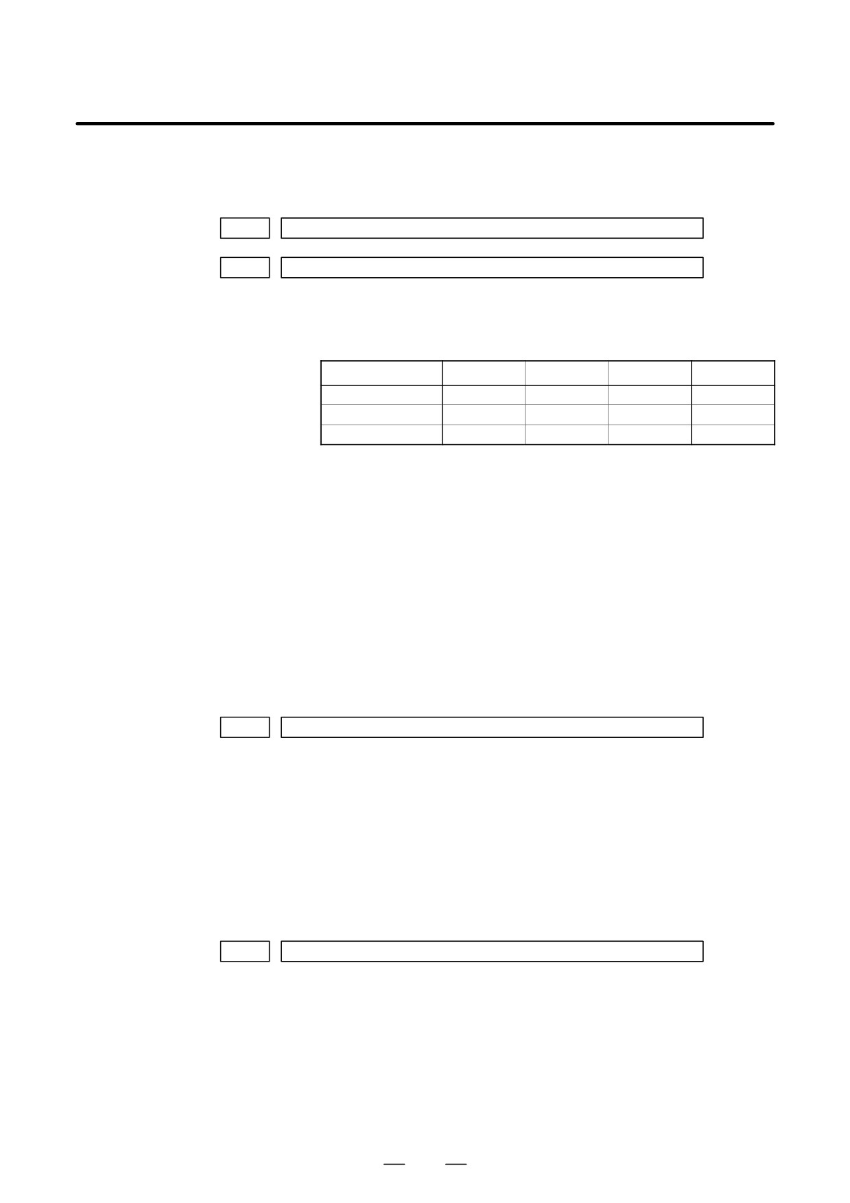
1. DISPLAY AND OPERATION
B-63525EN/02
D Machine coordinates of
angular axis/orthogonal
axis
DGN
306
Machine coordinates of a slant axis in the Cartesian coordinate system
DGN
307
Machine coordinates of an orthogonal axis in the Cartesian coordinate system
[Data type]
Two-word
[Unit of data]
Increment system
IS-A
IS-B
IS-C
Unit
Metric input
0.01
0.01
0.01
mm
Inch input
0.001
0.001
0.001
inch
Rotation axis
0.01
0.01
0.01
deg
[Valid data range]
-99999999 to 99999999
These parameters are updated only when bit 0 (AAC) of parameter No.
8200 is set to 1, and any of the parameters below is set to 1:
D Bit 0 (AOT) of parameter No. 8201
D Bit 1 (AO2) of parameter No. 8201
D Bit 2 (AO3) of parameter No. 8201
D Bit 3 (QSA) of parameter No. 5009 (T series only)
D The interference check option is selected.
D Motor temperature
information
DGN
308
Servo motor temperature
[Data type]
Byte axis
[Unit of data]
_C
[Valid data range]
0 to 255
The αi servo motor coil temperature is indicated.
When the temperature reaches 140_C, an alarm about motor overheat is
issued.
DGN
309
Pulse coder temperature
[Data type] Byte axis
[Unit of data] _C
[Valid data range] 0 to 255
The temperature of the pulse coder printed circuit board is indicated.
When the temperature reaches
100_C (85_C for the atmosphere
temperature in the pulse coder), an alarm about motor overheat is issued.
72
B-63525EN/02
1. DISPLAY AND OPERATION
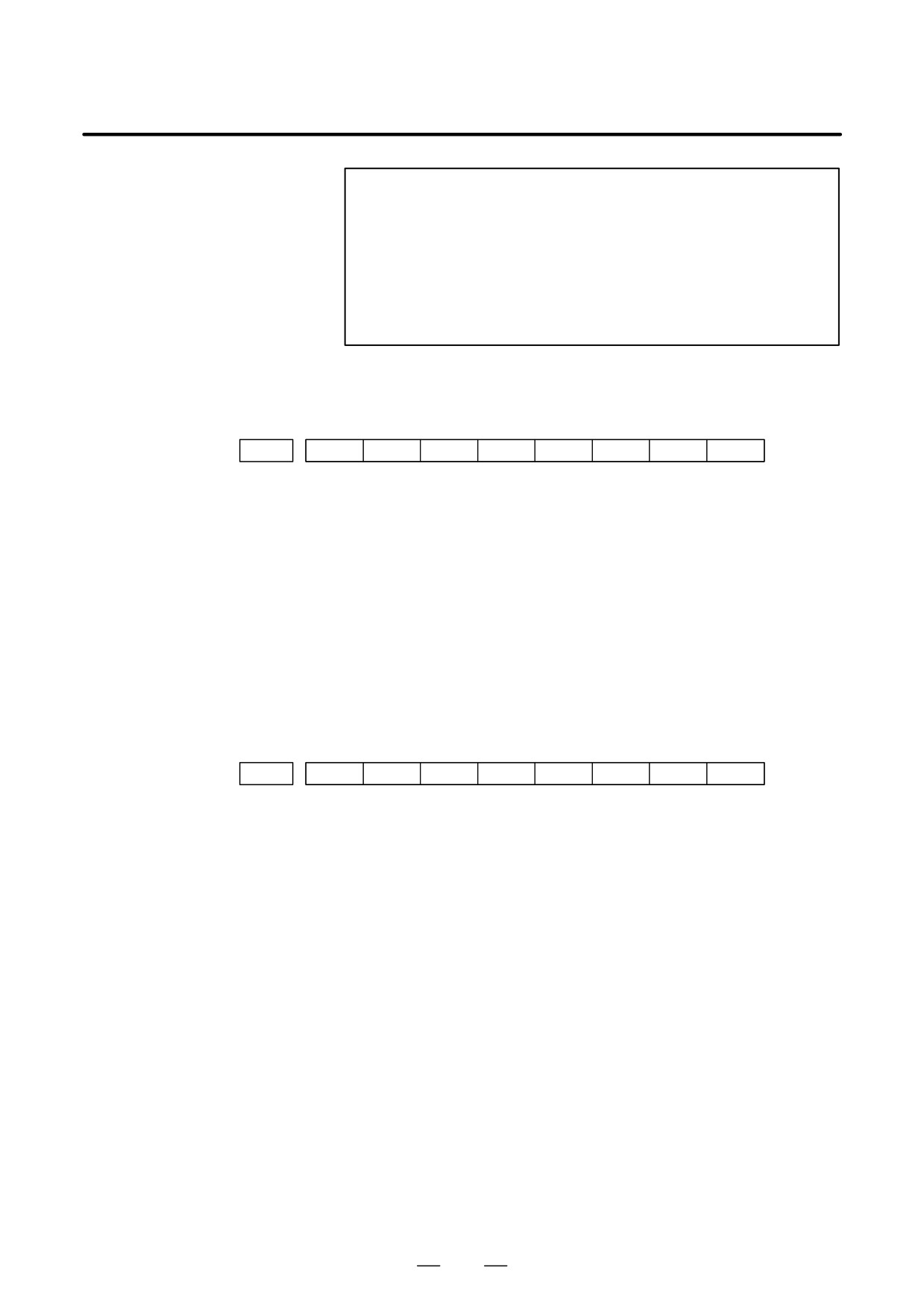
NOTE
1
The temperature data must fall within the following ranges.
50_C to 160_C "5_C
160_C to 180_C "10_C
2
The temperature at which an overheat alarm is issued has
a maximum error of 5_C.
3
Information on axes other than the αi servo axis is not
indicated.
(Indicated by ”0_C.”)
D Cause of the APZ bit (bit
4 of parameter 1815)
brought to 0
#7
#6
#5
#4
#3
#2
#1
#0
DGN
310
DTH
ALP
NOF
BZ2
BZ1
PR2
PR1
#0(PR1):
The setting of the following parameters has been changed: Parameters
1821, 1850, 1860, 1861.
#1(PR2):
The setting of the ATS bit (bit 1 of parameter 8302) has been changed.
#2(BZ1):
The detected APC battery voltage is 0 V (Inductosyn).
#3(BZ2):
The detected APC battery voltage is 0 V (separate position detector).
#4(NOF):
The Inductosyn output no offset data.
#5(ALP):
Before the α pulse coder detects a full single rotation, reference position
establishment by parameters was attempted.
#6(DTH):
A controlled axis detach signal/parameter was input.
#7
#6
#5
#4
#3
#2
#1
#0
DGN
311
DUA
XBZ
GSG
AL4
AL3
AL2
AL1
#0(AL1):
An APC alarm was issued.
#2(AL3):
The detected APC battery voltage is 0 V (serial pulse coder).
#3(AL4):
An abnormal rotation speed (RCAL) was detected.
#4(GSG):
The G202 signal was brought from 0 to 1.
#1(AL2):
A disconnection was detected.
#6(DUA):
While the dual position feedback function was being used, the difference
in error between the semi-closed loop side and the closed loop side
became too large.
#5(XBZ):
The detected APC battery voltage is 0 V (serial separate position
detector).
73
1. DISPLAY AND OPERATION
B-63525EN/02
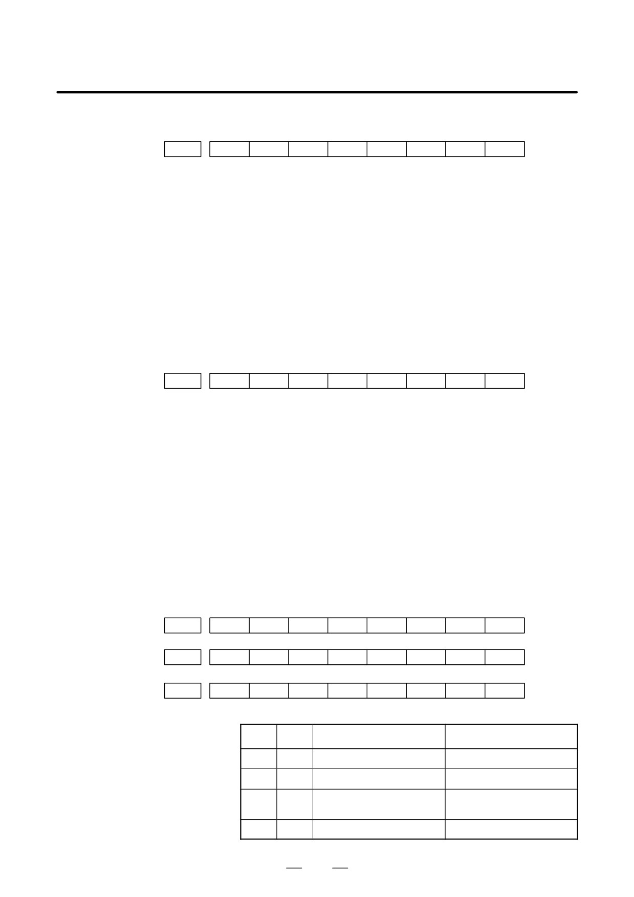
D FSSB status
#7
#6
#5
#4
#3
#2
#1
#0
DGN
320
CFE
ERR
ERP
OPN
RDY
OPP
CLS
Indicates the internal status of the FSSBC.
#0(CLS): Closed.
#1(OPP): Running OPEN protocol.
#2(RDY): Open and ready.
#3(OPN): Open.
#4(ERP): Running ERROR protocol.
#5(ERR):
#7(CFE): Encountered configuration error.
(The actual slave type does not match the one specified in the conversion
table.)
#7
#6
#5
#4
#3
#2
#1
#0
DGN
321
XE3
XE2
XE1
XE0
ER3
ER2
ER1
ER0
Indicates the cause of an FSSBC error.
#0(ER0):
INFORMED ERROR
#1(ER1):
(RESERVE)
#2(ER2):
Master port disconnection
#3(ER3):
External EMG input
Indicates the cause of an FSSBC error resulting from a request from a slave.
#4(XE0):
(RESERVE)
#5(XE1):
Slave port disconnection
#6(XE2):
Master port disconnection
#7(XE3):
External EMG input
#7
#6
#5
#4
#3
#2
#1
#0
DGN
330
EXT
DUA
ST1
ST0
#7
#6
#5
#4
#3
#2
#1
#0
DGN
332
EXT
DUA
ST1
ST0
to
#7
#6
#5
#4
#3
#2
#1
#0
DGN
348
EXT
DUA
ST1
ST0
#0, #1(ST0, ST1):
Indicates the type code for an actually connected slave.
ST1
ST0
Type
Address
0
0
A
Servo amplifier
0
1
(B: RESERVE)
(Currently nonexistent)
1
0
C
Stand-alone type detector inter-
face unit
1
1
(RESERVE)
(Currently nonexistent)
74
B-63525EN/02
1. DISPLAY AND OPERATION
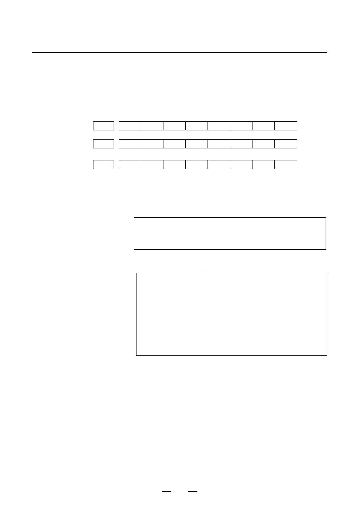
#2(DUA):
0 : The slave of interest is not on the first axis of the two-axis amplifier.
1 : The slave of interest is on the first axis of the two-axis amplifier.
#3(EXT):
0 : The slave of interest does not exist.
1 : The slave of interest exists.
#7
#6
#5
#4
#3
#2
#1
#0
DGN
331
DMA
TP1
TP0
HA2
HA1
HA0
#7
#6
#5
#4
#3
#2
#1
#0
DGN
333
DMA
TP1
TP0
HA2
HA1
HA0
to
#7
#6
#5
#4
#3
#2
#1
#0
DGN
349
DMA
TP1
TP0
HA2
HA1
HA0
#0, #1, #2(HA0, HA1, HA2):
Indicates the host LSI address specified as a DMA destination.
#3, #4 (TP0, TP1):
Indicates the type code of a specified slave.
(See the above descriptions about ST0 and ST1.)
#5(DMA):
Indicates a value determining whether to allow DMA to occur.
NOTE
A combination of parameter Nos. 330 and 331 corresponds
to one FSSB slave unit. Up to ten slave units are available.
Slave units and the associated diagnosis numbers
Slave unit 00
³
Diagnosis No. 330, No. 331
Slave unit 01
³
Diagnosis No. 332, No. 333
Slave unit 02
³
Diagnosis No. 334, No. 335
Slave unit 03
³
Diagnosis No. 336, No. 337
Slave unit 04
³
Diagnosis No. 338, No. 339
Slave unit 05
³
Diagnosis No. 340, No. 341
Slave unit 06
³
Diagnosis No. 342, No. 343
Slave unit 07
³
Diagnosis No. 344, No. 345
Slave unit 08
³
Diagnosis No. 346, No. 347
Slave unit 09
³
Diagnosis No. 348, No. 349
75
1. DISPLAY AND OPERATION
B-63525EN/02
D Details of invalid servo
parameter setting alarms
(on the servo side)
DGN
352
Detail number for invalid servo parameter setting alarm
Indicates information that can be used to identify the location (parameter)
and cause of an invalid servo parameter setting alarm (servo alarm No.
417).
This diagnosis information is valid when the following conditions are
satisfied.
D Servo alarm No. 417 has occurred.
D Bit 4 of diagnosis No. 203 (PRM) = 1
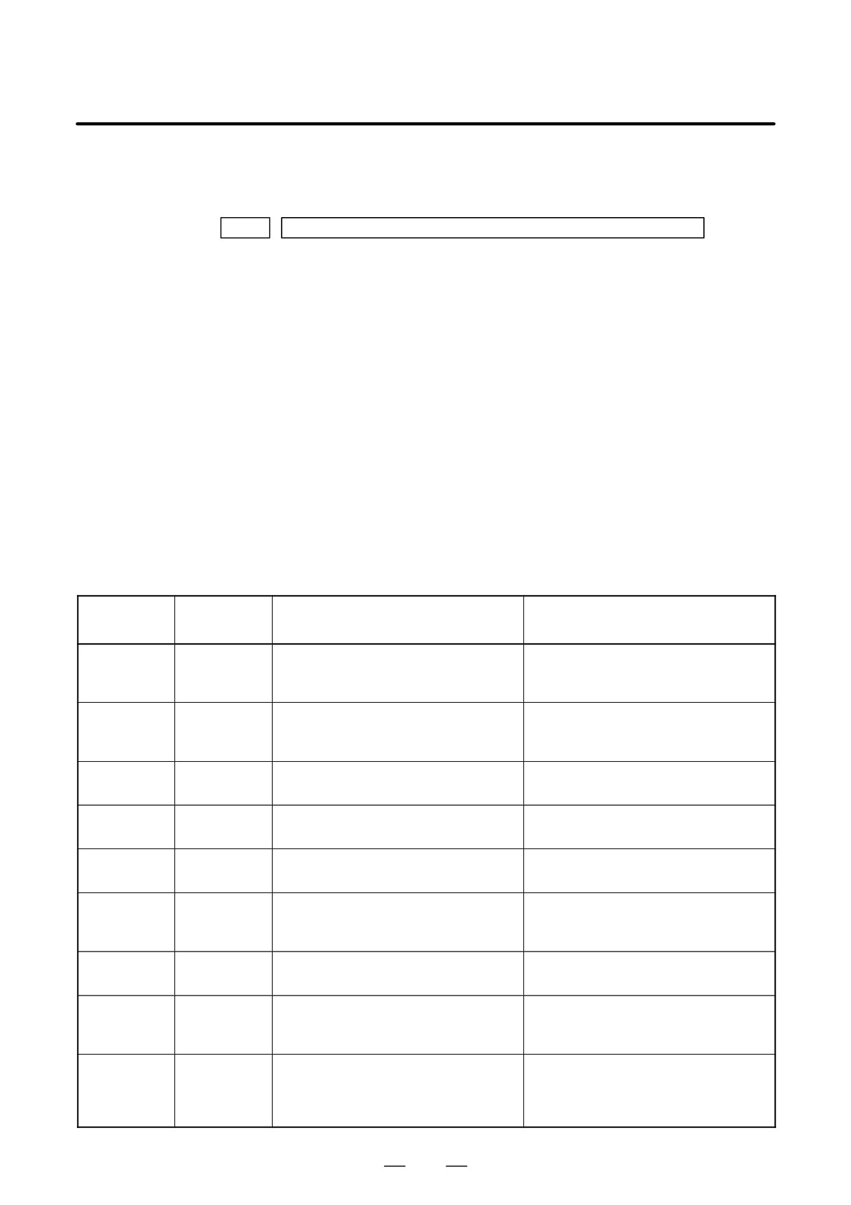
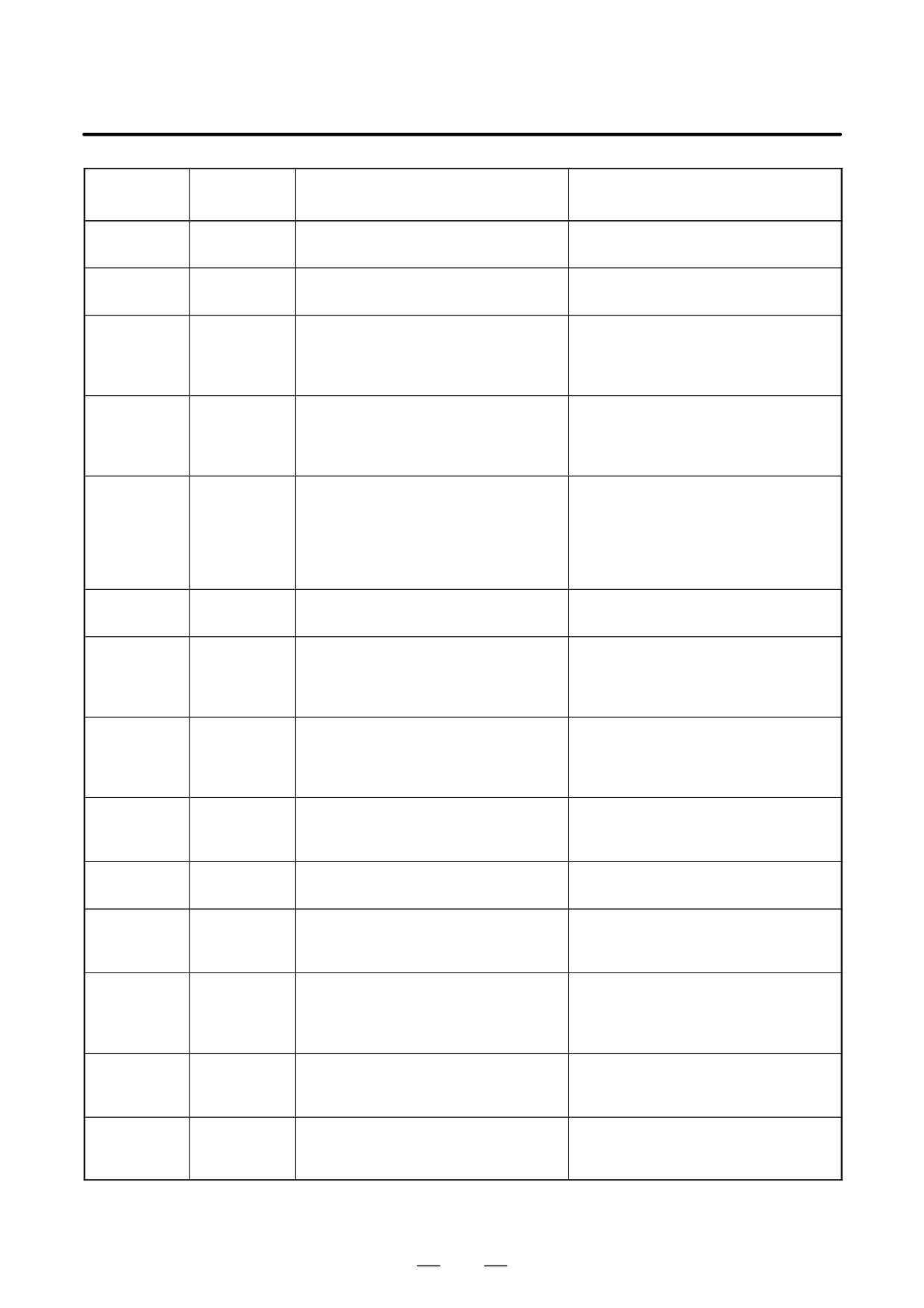
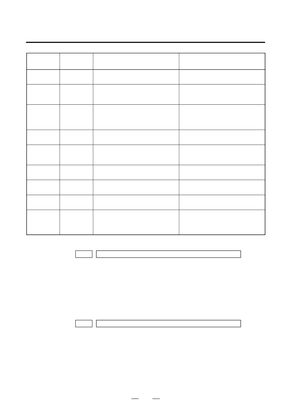
See the following table for the displayed detail numbers and the
corresponding causes. For further detail information that could be used
to take measures, refer to FANUC AC Servo Motor αi series Parameter
Manual (B-65270EN).
D Detailed descriptions
about invalid servo
parameter setting alarms
Detail
Parameter
Cause
Measure
number
number
0233
2023
A value specified as the number of veloc-
Decrease the value specified as the num-
ity pulses is greater than 13100 when ini-
ber of velocity pulses to within 13100.
tialization bit 0 = 1.
0243
2024
A value specified as the number of posi-
Decrease the value specified as the num-
tion pulses is greater than 13100 when
ber of position pulses to within 13100.
initialization bit 0 = 1.
0434
2043
The internal value of the velocity loop in-
Decrease the value specified in the veloc-
0435
tegration gain has overflowed.
ity loop integration gain parameter.
0444
2044
The internal value of the velocity loop pro-
Use a function for changing the internal for-
0445
portional gain has overflowed.
mat of the velocity loop proportional gain.
0474
2047
The internal value of the observer param-
Change the setting to: (-1) × (desired
0475
eter (POA1) has overflowed.
setting)/10
0534
2053
The internal value of the dead zone com-
Decrease the setting until the invalid pa-
0535
pensation parameter has overflowed.
rameter setting alarm will not occur any
longer.
0544
2054
The internal value of the dead zone com-
Decrease the setting until the invalid param-
0545
pensation parameter has overflowed.
eter setting alarm will not occur any longer.
0686
2068
The internal value of the feedforward co-
Use the position gain magnification func-
0687
efficient has overflowed.
tion.
0688
0694
2069
The interval value of the velocity feedfor-
Decrease the velocity feedforward coeffi-
0695
ward coefficient has overflowed.
cient.
0696
0699
76
B-63525EN/02
1. DISPLAY AND OPERATION
Detail
Parameter
Cause
Measure
number
number
0754
2075
The setting of the parameter listed at the
This parameter is presently not in use.
0755
left has overflowed.
Specify 0 in it.
0764
2076
The setting of the parameter listed at the
This parameter is presently not in use.
0765
left has overflowed.
Specify 0 in it.
0783
2078
The conversion coefficient parameter
Set a value in this parameter.
listed at the left has not been set up for a
full-closed loop linear motor (for the Se-
ries 9080 only).
0793
2079
The conversion coefficient parameter
Set a value in this parameter.
listed at the left has not been set up for a
full-closed loop linear motor (for the Se-
ries 9080 only).
0843
2084
No positive value has been set for the
Specify a positive value as the flexible
flexible feed gear numerator.
feed gear numerator.
Alternatively, the following condition ex-
Alternatively, satisfy the following condi-
ists: Feed gear numerator > denominator
tion: Feed gear numerator x denomina-
tor (except for phase A-/B-specific
stand-alone type detector).
0853
2085
No positive value has been set as the
Specify a positive value as the flexible
flexible feed gear denominator.
feed gear denominator.
0884
2088
The internal value of the machine velocity
Decrease the machine velocity feedback
0885
feedback coefficient has overflowed.
coefficient.
0886
Alternatively, use the damping control
function, which has an equivalent effect.
0883
2088
A value of 100 or greater was specified in
The maximum allowable value for the ma-
the machine velocity feedback coefficient
chine velocity feedback coefficient for axes
for an axis with a serial stand-alone type
with a serial stand-alone type detector is
detector.
100. Decrease the setting to within 100.
0926
2092
The interval value of the advance feedfor-
Use the position gain magnification func-
0927
ward coefficient has overflowed.
tion.
0928
0996
2099
The internal value for suppressing N
Decrease the setting of the parameter
pulses has overflowed.
listed at the left.
1123
2112
No value has been entered for the AMR
Specify the AMR conversion coefficient.
conversion coefficient parameter when a
linear motor is in use.
1183
2118
No value has been specified in the semi-/
Specify a semi-/full-closed loop error
full-closed loop error threshold parameter
threshold value for the parameter listed at
for a full-closed loop linear motor (for the
the left.
Series 9080 only).
1284
2128
If the value specified as the number of ve-
Decrease the value for the parameter
1285
locity pulses is small, the internal value of
listed at the left to within a range where no
the current control parameter overflows.
alarm will occur any longer.
1294
2129
If the value specified as the number of ve-
Re-set “a” to a smaller value when the
1295
locity pulses is large, the internal value of
setting of the parameter listed at the left is
the current control parameter overflows.
broken up into: a × 256 + b
77
1. DISPLAY AND OPERATION
B-63525EN/02
Detail
Parameter
Cause
Measure
number
number
1393
2139
The setting of the linear motor AMR offset
Decrease the setting of the parameter
has exceeded ±45.
listed at the left to within ±45.
1446
2144
The cutting feedforward coefficient for the
Use the position gain magnification func-
1447
cutting-/rapid traverse-specific FAD func-
tion.
1448
tion has overflowed.
1454
2145
The cutting velocity feedforward coeffi-
Decrease the velocity feedforward coeffi-
1455
cient for the cutting-/rapid traverse-spe-
cient.
1456
cific FAD function has overflowed.
1459
8213
1821
No positive value has been set in the ref-
Specify a positive value in the parameter
erence counter capacity parameter.
listed at the left.
8254
1825
The internal value of the position gain has
Use the position gain magnification func-
8255
overflowed.
tion.
8256
10016
2200 bit 0
The internal value of a parameter used to
Do not use the runaway detection func-
10019
detect runaway has overflowed.
tion (specify bit 0 = 1).
10043
1815#1
A full-closed loop has been set up for a
A full-closed loop cannot be specified for
2010#2
linear motor (except for the Series 9080).
linear motors.
10053
2018#0
The scale reverse connection bit has
The scale reverse connection bit cannot
been set up for a linear motor.
be used for linear motors.
10062
2209#4
The amplifier in use does not support the
If you want to use this amplifier, reset the
HC alarm avoidance function.
function bit listed at the left to 0.
If you want to use the HC alarm avoidance
function, use an amplifier that supports it.
D Error detection
DGN
360
Cumulative command pulse count (NC)
[Data type]
Two-word axis
[Unit of data]
Detection unit
[Valid data range]
-99999999 to 99999999
Indicates the cumulative count of movement commands distributed from
the CNC since the power was switched on.
DGN
361
Cumulative compensation pulse count (NC)
[Data type]
Word axis
[Unit of data]
Detection unit
[Valid data range]
-32767 to 32767
Indicates the cumulative count of compensation pulses
(backlash
compensation, pitch error compensation, etc.) distributed from the CNC
since the power was switched on.
78
B-63525EN/02
1. DISPLAY AND OPERATION
DGN
362
Cumulative command pulse count (SV)
[Data type]
Two-word axis
[Unit of data]
Detection unit
[Valid data range]
-99999999 to 99999999
Indicates the cumulative count of movement command and compensation
pulses received at the servo section since the power was switched on.
DGN
363
Cumulative feedback pulse count (SV)
[Data type]
Two-word axis
[Unit of data]
Detection unit
[Valid data range]
-99999999 to 99999999
Indicates the cumulative count of position feedback pulses received from
the pulse coder by the servo section.
D Diagnostic data related
to the Inductosyn
absolute position
detector
DGN
380
Difference between the absolute position of the motor and offset data
[Data type]
Two-word axis
[Units of data]
Detection units
M (absolute position of the motor) - S (offset data)
λ(pitch interval)
The remainder resulting from the division is displayed.
DGN
381
Offset data from the Inductosyn
[Data type] Two-word axis
[Units of data] Detection units
Off set data is displayed when CNC calculates the machine position.
79
1. DISPLAY AND OPERATION
B-63525EN/02
D Flexible synchronization
error
DGN
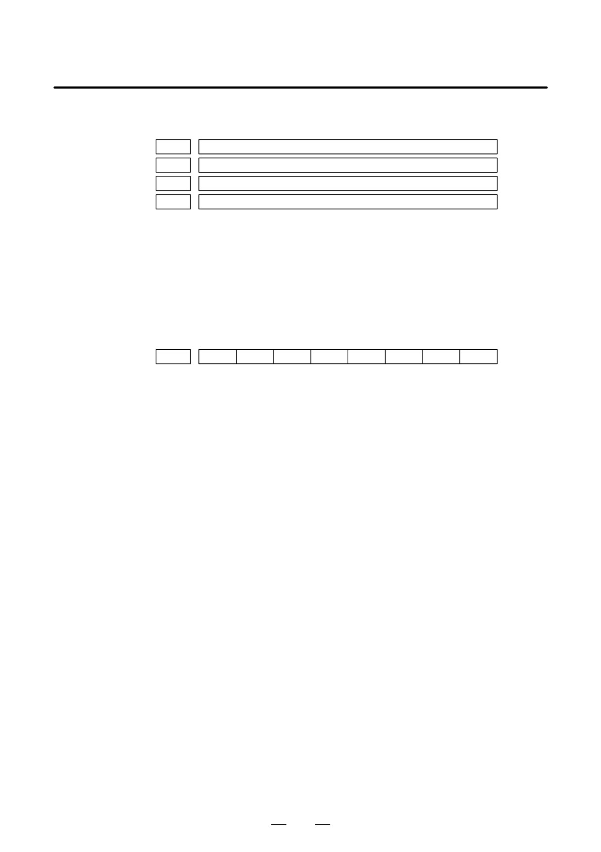
390
Flexible synchronization error (A)
DGN
391
Flexible synchronization error (B)
DGN
392
Flexible synchronization error (C)
DGN
393
Flexible synchronization error (D)
[Data type]
Two-word
[Units of data]
Detection units
[Valid data range]
-99999999 to 99999999
The difference between the error of the master axis of each group set with
the flexible synchronization function and a master axis error found from
the slave axis is displayed.
D Serial spindle
#7
#6
#5
#4
#3
#2
#1
#0
DGN
400
SAI
SS2
SSR
POS
SIC
#4(SAI)
0 : Spindle analog control is not used.
1 : Spindle analog control is used.
#3(SS2)
0 : Spindle serial doesn’t control 2nd spindle.
1 : Spindle serial control 2nd spindle.
#2(SSR)
0 : Spindle serial control is not performed.
1 : Spindle serial control is performed.
#1 (POS)
A module required for spindle analog control is
0 : not mounted
1 : mounted
#0 (SIC)
A module required for spindle serial control is
0 : not mounted
1 : mounted
80
B-63525EN/02
1. DISPLAY AND OPERATION
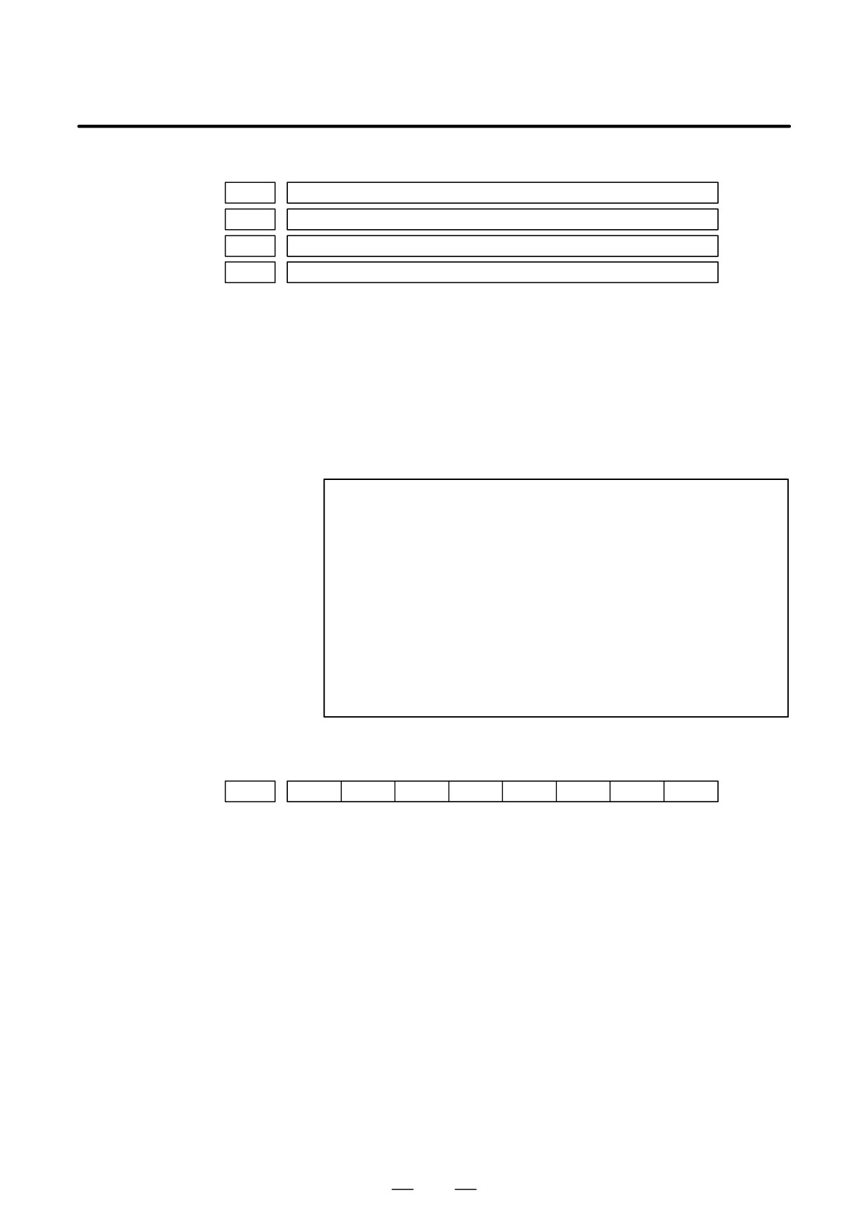
DGN
401
Serial spindle alarm state of First spindle
DGN
402
Serial spindle alarm state of Second spindle
DGN
403
First spindle motor temperature
DGN
404
Second spindle motor temperature
[Data type]
Byte
[Unit of data]
_C
[Valid data range]
0 to 255
The αi spindle motor coil temperature is indicated.
This temperature is used as a guideline for occurrence of the spindle
overheat alarm.
(However, the temperature at which overhear occurs varies with the
motor.)
NOTE
1
The temperature data must fall within the following ranges.
D 50_C to 160_C "5_C
D 160_C to 180_C "10_C
2
The indicated temperature and the temperature at which
overhear occurs have the following errors.
D 160_C or less
Up to 5_C
D 160_C to 180_C
Up to 10_C
3
For spindles older than the αi spindle, this function is invalid.
4
When the system configuration of the spindle (even another
spindle) includes an additional spindle older than the αi
spindle, this function is invalid.
#7
#6
#5
#4
#3
#2
#1
#0
DGN
408
SSA
SCA
CME
CER
SNE
FRE
CRE
#0 (CRE): A CRC error occurred. (Warning)
#1 (FRE): A framing error occurred. (Warning)
#2 (SNE): The transmission/reception target is invalid.
#3 (CER): An error occurred during reception.
#4 (CME): No response was returned during automatic scanning.
#5 (SCA): A communication alarm occurred on the spindle amplifier side.
#7 (SSA): A system alarm occurred on the spindle amplifier side.
(These problems cause spindle alarm 749. Such problems are mainly
caused by noise, disconnection, or instantaneous power-off).
81
1. DISPLAY AND OPERATION
B-63525EN/02
#7
#6
#5
#4
#3
#2
#1
#0
DGN
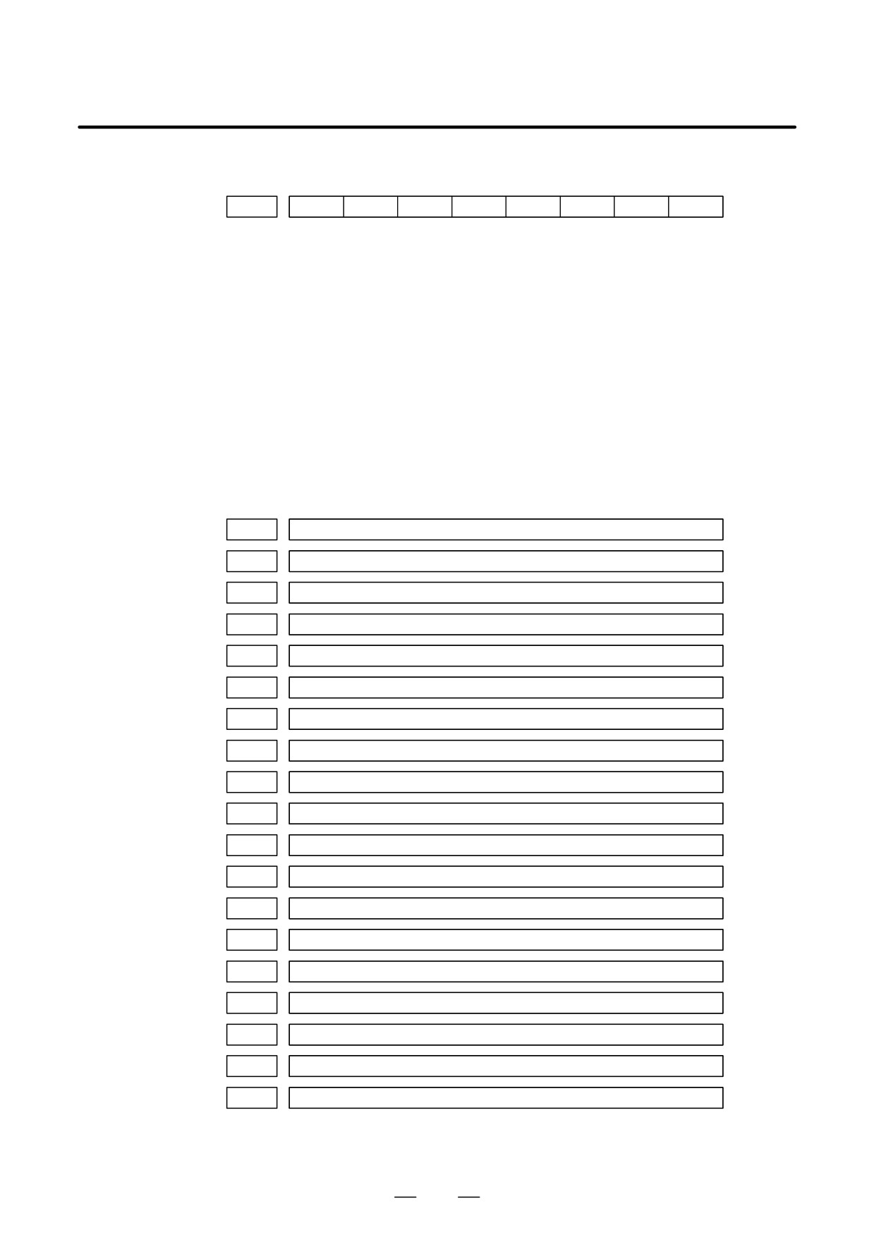
409
SPE
S2E
S1E
SHE
Refer to this diagnosis when alarm 750 has generated.
#3 (SPE)
In spindle serial control serial spindle parameters
0 : Satisfy start condition of spindle unit
1 : Do not satisfy start condition of spindle unit
#2 (S2E)
0 : 2nd spindle started normally in spindle serial control.
1 : 2nd spindle did not start normally in spindle serial control.
#1 (S1E)
0 : 1st spindle started normally in spindle serial control.
1 : 1st spindle did not start normally in spindle serial control.
#0 (SHE)
0 : Serial communication module is correct on CNC side.
1 : An error occurred in serial communication module on CNC side
DGN
410
Load meter of 1st spindle [%]
DGN
411
Speed meter of 1st spindle [min-1]
DGN
412
Load meter of 2nd spindle [%]
DGN
413
Speed meter of 2nd spindle [min-1]
DGN
414
Position error in 1st spindle synchronous control mode
DGN
415
Position error in 2nd spindle synchronous control mode
DGN
416
Absolute value of synchronization error between 1st and 2nd spindles
DGN
417
Feedback information of 1st spindle position coder
DGN
418
Position error of 1st spindle position loop mode
DGN
419
Feedback information of 2nd spindle position coder
DGN
420
Feedback information of 2nd spindle position coder
DGN
421
Feedback information of the position coder of the third spindle
DGN
422
Position deviation in the position loop mode of the third spindle
DGN
423
Feedback information of the position coder of the fourth spindle
DGN
424
Position deviation in the position loop mode of the fourth spindle
DGN
425
First-spindle synchronization error
DGN
426
Second-spindle synchronization error
DGN
427
Third-spindle synchronization error
DGN
428
Fourth-spindle synchronization error
No. 425 to 428:
Indicates the absolute value of a synchronization error in synchronization
mode where each spindle is treated as a slave axis.
82
B-63525EN/02
1. DISPLAY AND OPERATION
#7
#6
#5
#4
#3
#2
#1
#0
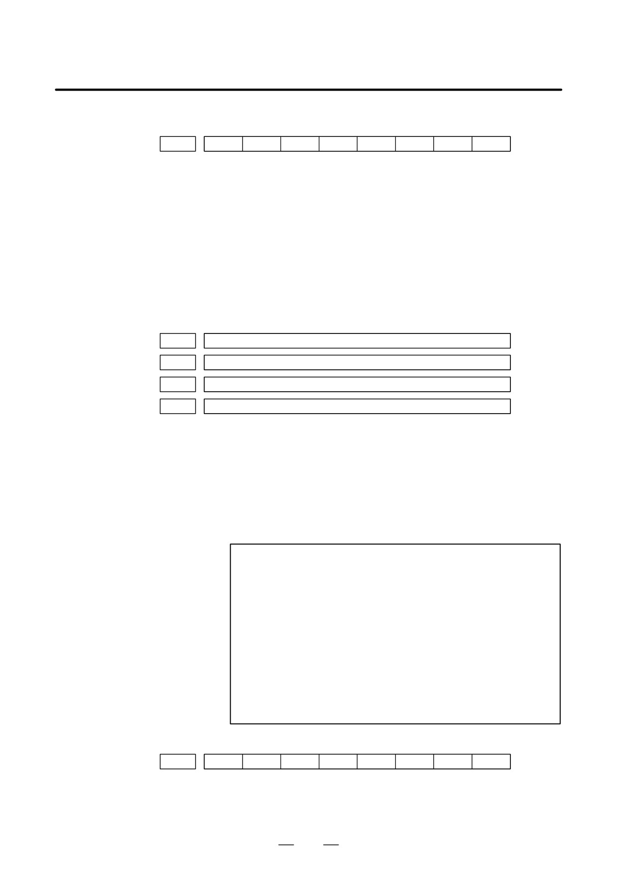
DGN
430
SS4
SS3
SSR
SIC
#4(SS4)
0 : Specifies not to use the fourth spindle under spindle serial control.
1 : Specifies to use the fourth spindle under spindle serial control.
#3(SS3)
0 : Specifies not to use the third spindle under spindle serial control.
1 : Specifies to use the third spindle under spindle serial control.
#2(SSR)
0 : Spindle serial control (third and fourth spindles) not in progress.
1 : Spindle serial control (third and fourth spindles) in progress.
#0(SIC)
Indicates whether a module necessary for spindle serial control (third and
fourth spindles) has been installed, as follows:
0 : Not installed
1 : Installed
DGN
431
Alarm status of the third serial spindle
DGN
432
Alarm status of the fourth serial spindle
DGN
433
Third spindle motor temperature
DGN
434
Fourth spindle motor temperature
[Data type]
Byte
[Unit of data]
_C
[Valid data range]
0 to 255
The αi spindle motor coil temperature is indicated.
This temperature is used as a guideline for occurrence of the spindle
overheat alarm.
(However, the temperature at which overhear occurs varies with the
motor.)
NOTE
1
The temperature data must fall within the following ranges.
D 50_C to 160_C "5_C
D 160_C to 180_C "10_C
2
The indicated temperature and the temperature at which
overhear occurs have the following errors.
D 160_C or less
Up to 5_C
D 160_C to 180_C
Up to 10_C
3
For spindles older than the αi spindle, this function is invalid.
4
When the system configuration of the spindle (even another
spindle) includes an additional spindle older than the αi
spindle, this function is invalid.
#7
#6
#5
#4
#3
#2
#1
#0
DGN
438
Information about communication errors for spindle serial control (third
and fourth spindles).
For contents, see the descriptions about diagnosis No. 408.
83
1. DISPLAY AND OPERATION
B-63525EN/02
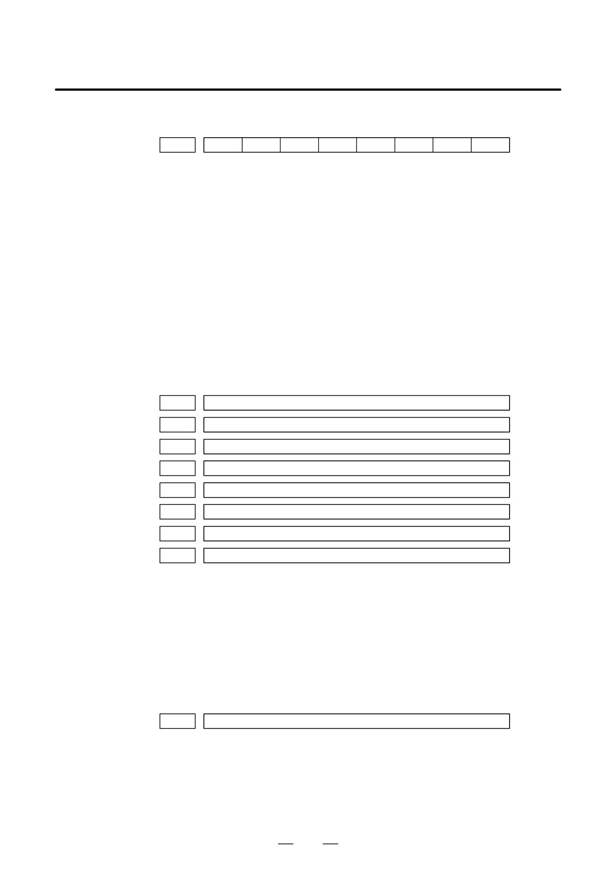
#7
#6
#5
#4
#3
#2
#1
#0
DGN
439
SPE
S4E
S3E
SHE
#3(SPE):
Indicates the state of the serial spindle parameter (third and fourth
spindles) for spindle serial control, as follows:
0 : The start condition for the spindle unit is satisfied.
1 : The start condition for the spindle unit is not satisfied.
#2(S4E):
0 : The fourth spindle was started normally under spindle serial control.
1 : The fourth spindle was not started normally under spindle serial
control.
#1(S3E):
0 : The third spindle was started normally under spindle serial control.
1 : The third spindle was not started normally under spindle serial
control.
#0(SHE):
Indicates the state of the serial communication module (third and fourth
spindles) on the CNC side as follows:
0 : Normal
1 : Abnormal
DGN
440
Third-spindle load meter indication [%]
DGN
441
Third-spindle speedometer indication [min-1]
DGN
442
Fourth-spindle load meter indication [%]
DGN
443
Fourth-spindle speedometer indication [min-1]
DGN
445
First-spindle position data
DGN
446
Second-spindle position data
DGN
447
Third-spindle position data
DGN
448
Fourth-spindle position data
[Data type]
Word
[Unit of data]
Pulse
[Valid data range]
0 to 4095
This parameter is valid when bit 1 of parameter No. 3117 = 1.
To display the position data of a spindle, execute spindle orientation.
D Diagnostic data related
to rigid tapping
DGN
450
Spindle position error during rigid tapping
[Data type]
Word
[Unit of data]
Detection units
84
B-63525EN/02
1. DISPLAY AND OPERATION
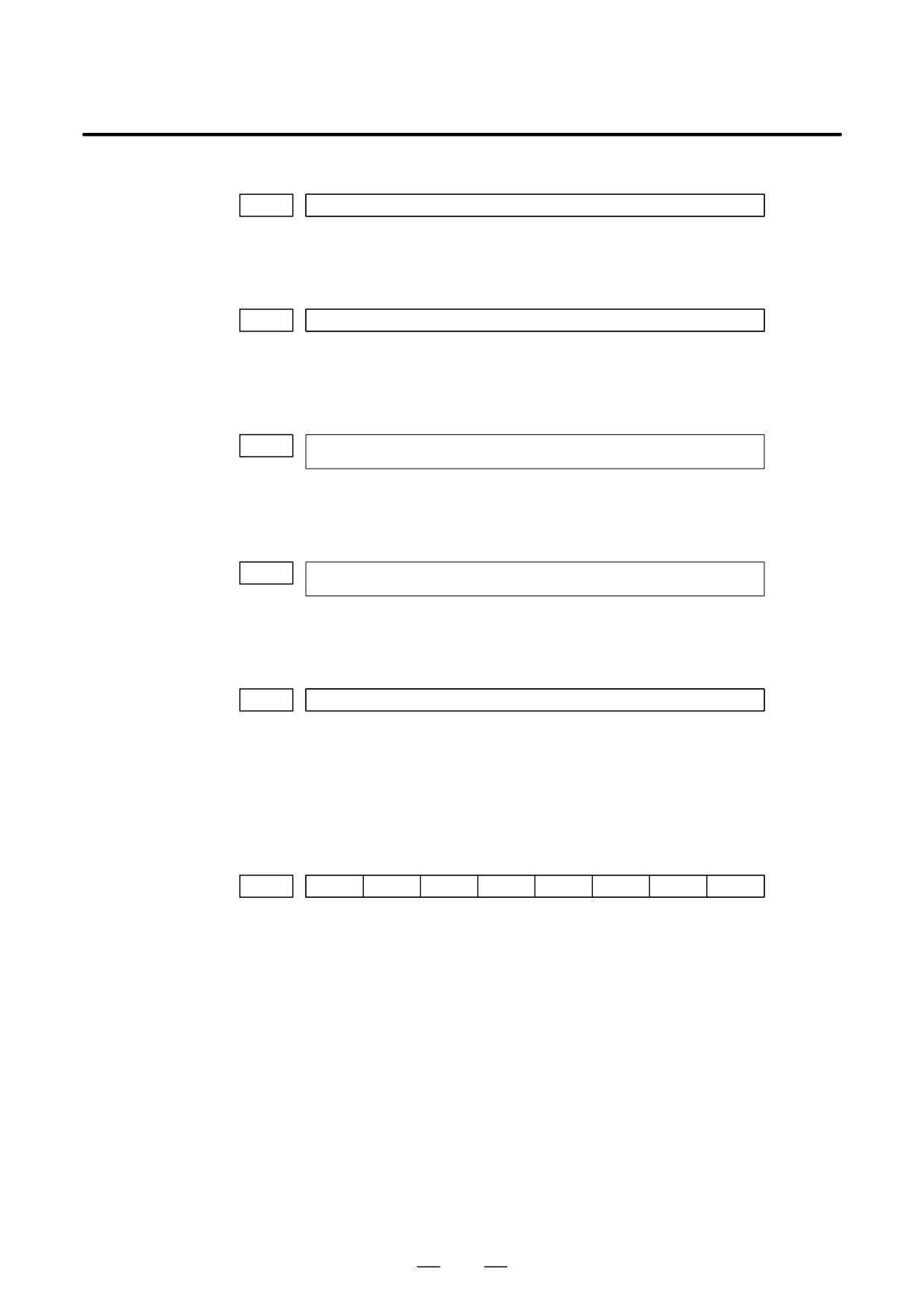
DGN
451
Spindle distribution during rigid tapping
[Data type] Word
[Unit of data] Detection units
DGN
454
Accumulated spindle distribution during rigid tapping
[Data type] Two-word
[Unit of data] Detection units
DGN
455
Instantaneous difference for the move command, calculated in terms of the spindle,
during rigid tapping (signed, accumulated value)
[Data type] Two-word
[Unit of data] Detection units
DGN
456
Instantaneous difference for the travel error, calculated in terms of the spindle,
during rigid tapping (signed)
[Data type] Word
[Unit of data] Detection units
DGN
457
Width of synchronization error during rigid tapping (maximum value)
[Data type] Word
[Unit of data] Detection units
D Two-spindle polygon
This data indicates the status of the polygon synchronization mode.
machining
(T series only)
#7
#6
#5
#4
#3
#2
#1
#0
DGN
470
SC0
LGE
SCF
PST
SPL
#0(SPL): Spindle polygon synchronization is in progress.
#1(PST): Spindle polygon synchronization mode is starting.
#2: Spindle polygon synchronization mode is being released.
#3: The spindle speed is being changed in spindle polygon synchronization
mode.
#4(SCF): The spindle speed has been changed in spindle polygon synchronization
mode.
#5: Not used
#6(LGE): In spindle polygon synchronization mode, the two spindles have different
loop gains.
#7(SC0): In spindle polygon synchronization mode, the specified speed is zero.
85

1. DISPLAY AND OPERATION
B-63525EN/02
CAUTION
1
If SPL and SCF are set to 1 and #1, #2, and #3 are set to 0 in polygon synchronization mode,
the operation is normal.
2
If the status does not change, even though PST is set to 1 and the program is stopped in a block
including G51.2, one of the spindles cannot attain the polygon synchronization speed. This
may occur when the spindle cannot be activated because the PSTU bit (bit 7 of parameter No.
7603) is set to 0.
3
LGE is set to 1 when the speed is changed in polygon synchronization mode if the serial spindle
control unit uses different loop gains for the first and second spindles during spindle
synchronization.
When this function is used, the two spindles must be controlled with an identical loop gain. The
warning is displayed in DGN, but the warning does not cause an alarm.
(The serial spindle
control unit switches parameters according to the statuses of CTH1, CTH2, and other signals.)
4
SCO is set to 1 if either of the following occurs: The combination of the programmed S value
and spindle control signals including *SSTP <G0029, #6>, SOV0 to SOV7 <G0030> and
multispindle control signal <G0027> causes 0 or a value smaller than the resolution of spindle
control to be programmed (the programmed value multiplied by 4095/highest-spindle-speed
is smaller than 1).
Alternatively, SIND control <G0032, G0033> is used and the programmed output is 0.
When SCO is set to 1, the spindle speed becomes 0, setting bit 0 of DGN 471 to 1 and disabling
the ratio of polygon synchronization rotation. This, however, is handled as a result of the
program, and does not cause P/S alarm No. 5018.
86
B-63525EN/02
1. DISPLAY AND OPERATION
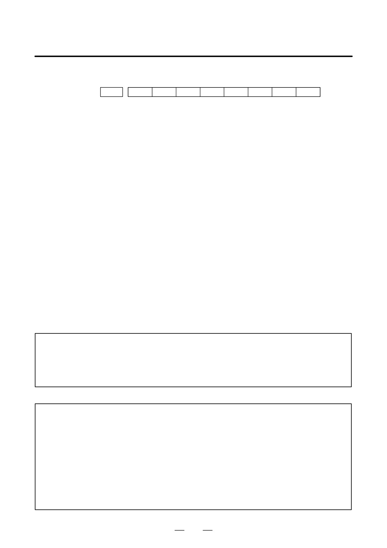
This data indicates the cause of P/S alarm 5018 or 218.
#7
#6
#5
#4
#3
#2
#1
#0
DGN
471
NPQ
PQE
NSP
SUO
QCL
PCL
#0 to #3
Cause of P/S alarm No. 5018
P/S alarm No. 5018 can be cleared by issuing a reset. The cause indication
is retained until the cause is removed or until polygon synchronization
mode is released.
#4 to #7
Cause of P/S alarm No. 218
If P/S alarm No. 218 occurs, polygon synchronization mode is released.
The cause indication, however, is retained until P/S alarm No. 218 is
cleared by issuing a reset.
#0:
The speed specified for spindle polygon synchronization is too low. (The
unit speed becomes 0 for internal operations.)
#1(PCL):
The first spindle (master axis in polygon synchronization) is clamped.
#2(QCL):
The second spindle (slave axis in polygon synchronization) is clamped.
#3(SUO):
The speed specified in spindle polygon synchronization is too high. (The
speed is restricted to the upper limit for internal operations.)
#4(NSP):
A spindle required for control is not connected.
(The serial spindle,
second spindle, etc. is not connected.)
#5:
A negative Q value is specified while the QDRC bit (bit 1 of parameter
No. 7603) is set to 1.
#6(PQE):
The P value or Q value, specified with G51.2, falls outside the predetermined
range. Alternatively, the P and Q values are not specified as a pair.
#7(NPQ):
Although the P and Q values are not specified with G51.2, an R value is
specified. Alternatively, none of the P, Q, or R value is specified.
CAUTION
Bit 0 is set to 1 even when the specified spindle speed is 0 (bit 7 of DGN 470 is set to 1). This,
however, does not cause P/S alarm No. 5018 to be output (because the programmed speed
is 0). P/S alarm No. 5018 occurs when bit 7 of DGN 470 is set to 0, while bit 0 of DGN 471 is
set to 1. Normal spindle speeds will not cause this alarm to be output.
NOTE
1
PCL indicates that the speed specified for the master axis exceeds the maximum speed for the
first axis, specified in parameters No. 3741 to 3744, causing, the specified speed to be limited
to the maximum speed.
PCL is not set to 1 provided the first spindle is connected correctly.
2
QCL is set to 1 when the polygon synchronization speed specified for the second spindle (slave
axis in polygon synchronization) exceeds the value set in parameter No. 7621, causing the
actual speed to be limited to the specified value.
3
SUO occurs if the number of distributed pulses for ITP exceeds 32767, that is, if the speed
specified for the first axis, divided by the specified P value, exceeds 59998. In other words,
SUO occurs when a speed in excess of 59998 min-1 is specified for the first axis if P is set to
1.
87
1. DISPLAY AND OPERATION
B-63525EN/02
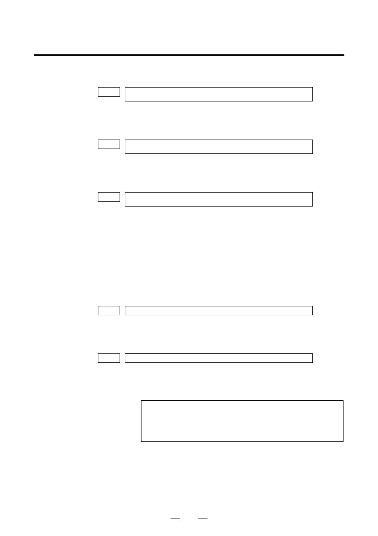
The specified synchronization mode status is displayed.
DGN
474
Rotation ratio of the master axis in spindle polygon synchronization
(specified P value)
In spindle polygon synchronization mode, the rotation ratio (specified P
value) of the current master axis (first spindle) is displayed.
DGN
475
Rotation ratio of the slave axis in spindle polygon synchronization
(specified Q value)
In spindle polygon synchronization mode, the rotation ratio (specified Q
value) of the current slave axis (second axis) is displayed.
DGN
476
Phase difference between two spindles in spindle polygon synchronization
(specified R value)
In spindle polygon synchronization mode, the current phase difference
(specified R value) is displayed.(The units are the minimum input
increment for the rotation axis of the machine.)
If the RDGN bit (bit 5 of parameter 7603) is set to 1, the shift amount
specified for the serial spindle (number of specified pulses, calculated at
a rate of 4096 pulses per 360 degrees) is displayed.
This diagnostic data indicates the actual speed of each spindle in
synchronization mode.
DGN
477
Actual speed of the master axis for spindle polygon synchronization (min-1)
In spindle polygon synchronization mode, the actual speed of the master
axis (first spindle) is displayed.
DGN
478
Actual speed of the slave axis in spindle polygon synchronization (min-1)
In spindle polygon synchronization mode, the actual speed of the slave
axis (second spindle) is displayed.
NOTE
The values of DGN 477 and DGN 478 are displayed without
being sampled. The displayed values may vary from the
actual values. Use these values for guidance only.
88
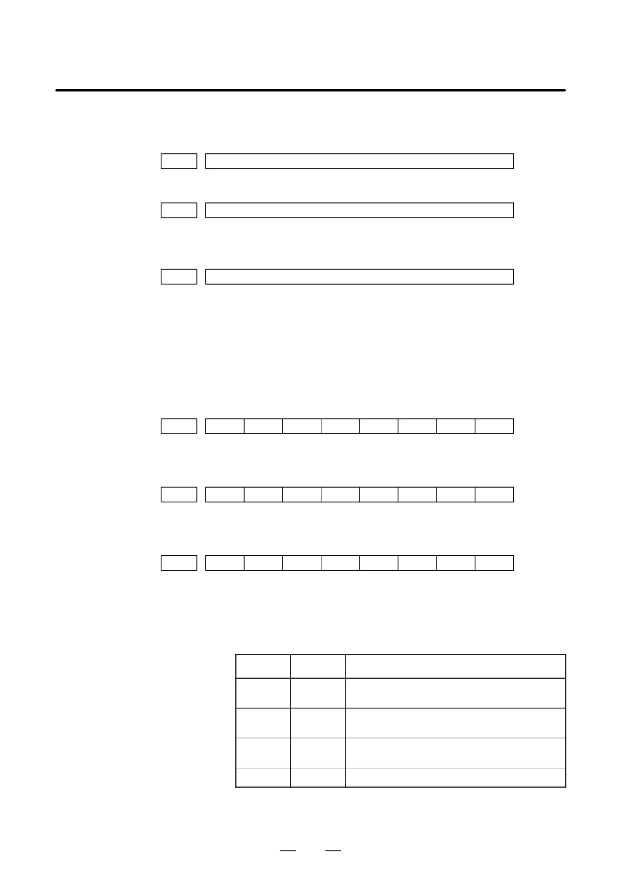
B-63525EN/02
1. DISPLAY AND OPERATION
D State of remote buffer
(protocol A)
DGN
500
Send command
1: SYN
2: RDY
3: RST
4: ALM
5: SAT
6: GTD
7: RTY
8: SDI
DGN
501
Receive command
1: SYN
2: RDY
3: ARS
4: AAL
5: CLB
6: SET
7: DAT
8: EOD
9: WAT
10: RTY 11:RDI
12: SDO
DGN
502
State of remote buffer
0 : Not ready
1 : Reset state
2 : Operation state
3 : Alarm state
4 : Circuit disconnection
D Open CNC
#7
#6
#5
#4
#3
#2
#1
#0
DGN
510
This data indicates the internal Open CNC information (not available to
general users).
#7
#6
#5
#4
#3
#2
#1
#0
DGN
511
This data indicates the internal Open CNC information (not available to
general users).
#7
#6
#5
#4
#3
#2
#1
#0
DGN
512
THH
THL
PRA
This data indicates the cause of a system alarm that has occurred in Open
CNC.
#0(PRA)
1 : A RAM parity error occurred in shared RAM.
#3, #2(THL, THH):
THL
THH
Status
0
0
A battery alarm has occurred in the PANEL i or CNC dis-
play unit with PC functions.
1
0
A high-temperature condition has occurred in the PANEL i
or CNC display unit with PC functions.
0
1
A low-temperature condition has occurred in the PANEL i
or CNC display unit with PC functions.
1
1
Normal (connected to the PC)
#4
0 : Normal
1 : An NMI has occurred in HSSB.
89
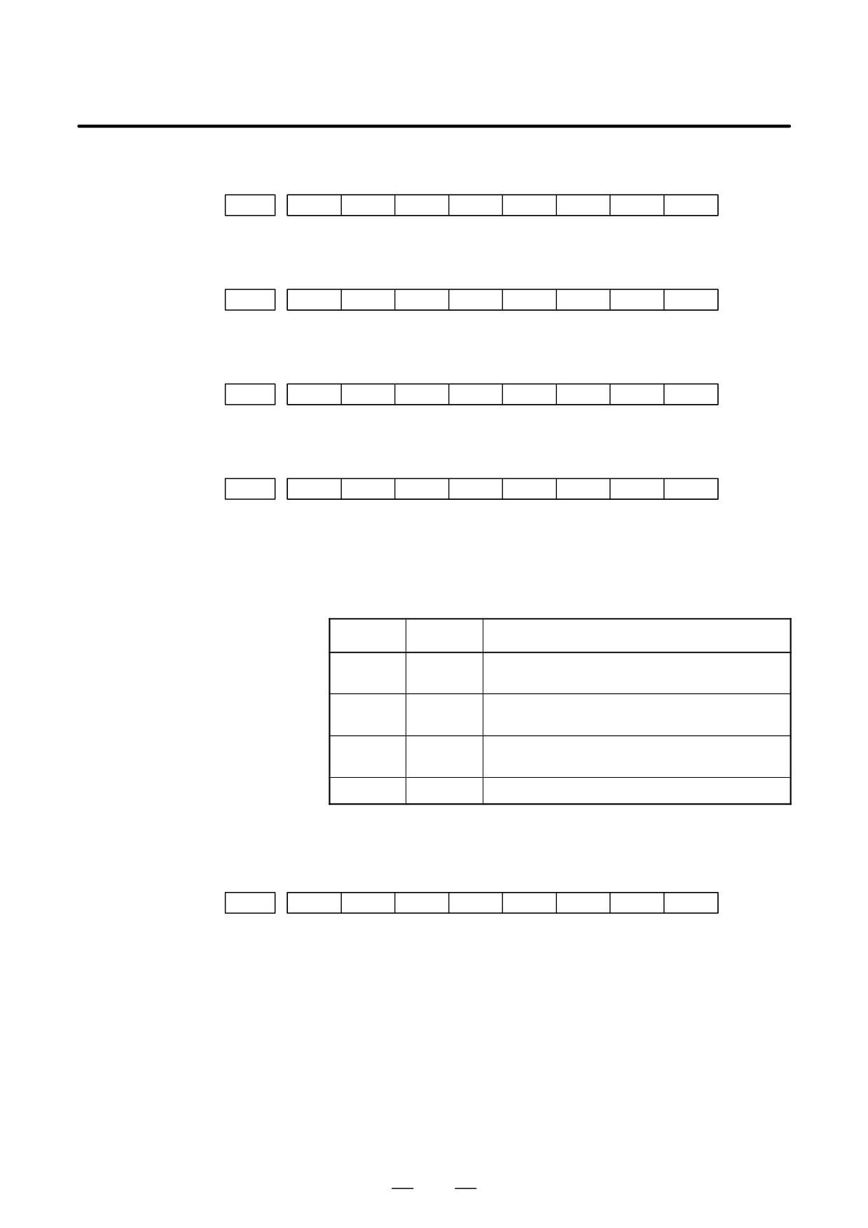
1. DISPLAY AND OPERATION
B-63525EN/02
#7
#6
#5
#4
#3
#2
#1
#0
DGN
513
Indicates the internal information about the HSSB (open CNC). (Hidden
function)
#7
#6
#5
#4
#3
#2
#1
#0
DGN
515
Indicates the internal information about the HSSB (channel 2). (Hidden
function)
#7
#6
#5
#4
#3
#2
#1
#0
DGN
516
Indicates the internal information about the HSSB (channel 2). (Hidden
function)
#7
#6
#5
#4
#3
#2
#1
#0
DGN
517
THH
THL
PRA
Indicates the internal information about the HSSB (channel 2) as follows.
#0(PRA):
0 : Normal
1 : A RAM parity error has occurred in shared RAM.
#3, #2(THL, THH):
THL
THH
Status
0
0
A battery alarm has occurred in the PANEL i or CNC dis-
play unit with PC functions.
1
0
A high-temperature condition has occurred in the PANEL i
or CNC display unit with PC functions.
0
1
A low-temperature condition has occurred in the PANEL i
or CNC display unit with PC functions.
1
1
Normal (connected to the PC)
#4:
0 : Normal
1 : An NMI has occurred in the HSSB.
#7
#6
#5
#4
#3
#2
#1
#0
DGN
518
Indicates the internal information about the HSSB (channel 2). (Hidden
function)
90
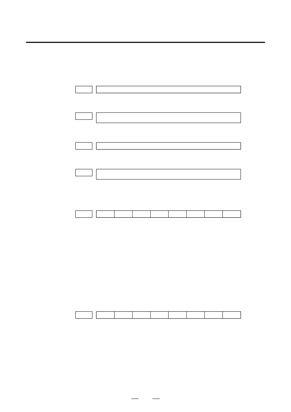
B-63525EN/02
1. DISPLAY AND OPERATION
D Diagnostic data related
to a small-diameter peck
drilling cycle (M series
only)
DGN
520
Total number of retractions during cutting after G83 is specified
Executing the G83 command clears the value to zero.
DGN
521
Total number of retractions made by receiving the overload signal during cutting
after G83 is specified
Executing the G83 command clears the value to zero.
DGN
522
Position on the drill axis from which retraction is started
The units are the same as the minimum input increment.
DGN
523
Difference between the position on the drill axis from which the previous retraction
was started and the position from which the current retraction is started
The units are the same as the minimum input increment.
D Diagnostic data related
to ATC for ROBO
DRILL α
#7
#6
#5
#4
#3
#2
#1
#0
DGN
530
A99
A98
A97
A96
A95
A43
* Check the contents of this data if alarm 251 is output.
#5 (A99):
A pry alarm occurred while the tool was being changed.
#4 (A98):
After the power was turned on or after an emergency stop was released,
M06 was specified before the first reference position return. While the
tool was being changed, machine lock was enabled for the Z-axis.
#3 (A97):
M06 is specified in canned cycle mode. M06 is specified in a block
containing the command instructing reference position return. M06 is
specified in tool compensation mode.
#2 (A96):
The current tool number parameter (parameter No. 7810) is set to 0.
#1 (A95):
M06 is specified while the Z-axis machine coordinate is positive.
#0 (A43):
A prohibited T code is specified after M06.
#7
#6
#5
#4
#3
#2
#1
#0
DGN
531
585
584
583
582
581
580
502
#6 (585):
Spindle servo alarm (excessive error during ATC magazine indexing)
#5 (584):
Invalid sequence during positioning and ATC (system error)
#4 (583):
Spindle servo alarm (LSI overflow)
#3 (582):
Spindle servo alarm (excessive drift)
#2 (581):
Spindle servo alarm (excessive error during travel)
#1 (580):
Spindle servo alarm (excessive error in the stop state)
#0 (502):
Large spindle distribution (system error)
91