FANUC Series 16i/160i/160is-MODEL B, Series 18i/180i/180is-MODEL B, Series 21i/210i/210is-MODEL B. MAINTENANCE MANAUL - page 8
2. LCD-MOUNTED TYPE i SERIES
HARDWARE
B-63525EN/02
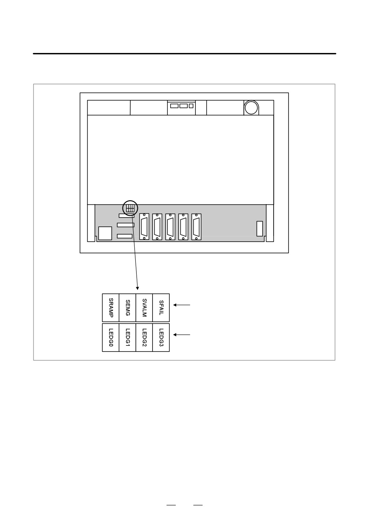
D LED display
Rear of unit
Alarm (red)
Status (green)
182
2. LCD-MOUNTED TYPE i SERIES
B-63525EN/02
HARDWARE
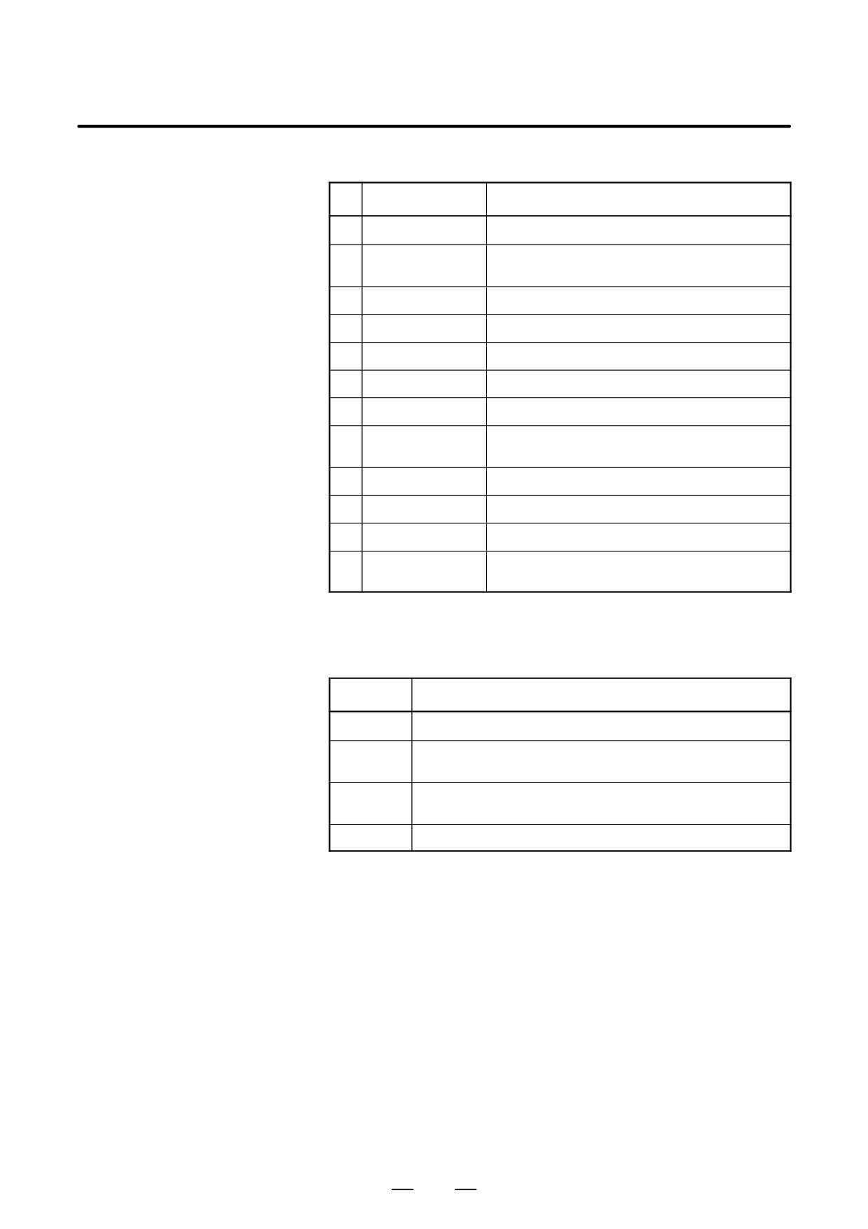
(1) Changes in status LED (green) indication at power-on time
No.
Status LED
Status
1
jjjj
Power is not supplied.
2
JJJJ
Initial status immediately after power is switched on; boot
is running.
3
jJJJ
System activation started.
4
JjJJ
Waiting for each processor ID in the system to be set up.
5
jjJJ
Each processor ID in the system has been set up.
6
JJjJ
FANUC bus initialized.
7
jJjJ
PMC initialized.
8
JjjJ
Information about the hardware configuration of each
printed-circuit board in the system has been set up.
9
jjjJ
PMC ladder initialized.
10
jJJj
Waiting for digital servo to be initialized.
11
JJJj
Digital servo initialized.
12
Jjjj
Initialization is completed, and normal operation is in
progress.
J: On j: Off
(2) Alarm LED (red) indication at system alarm occurrence
If any of these LEDs lights, it is likely that the hardware is defective.
Alarm LED
Meaning
SVALM
Servo alarm.
SEMG
Lights when a system alarm occurs.
The hardware has detected a failure in the system.
SFAIL
Lights when a system alarm occurs.
Used by the software to stop the system. Lights while boot is under way.
SRAMP
RAM parity or ECC alarm.
183
2. LCD-MOUNTED TYPE i SERIES
HARDWARE
B-63525EN/02
2.4.2
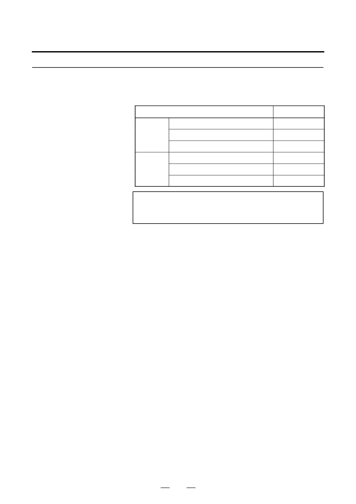
Inverter PCBs and
Connector Units
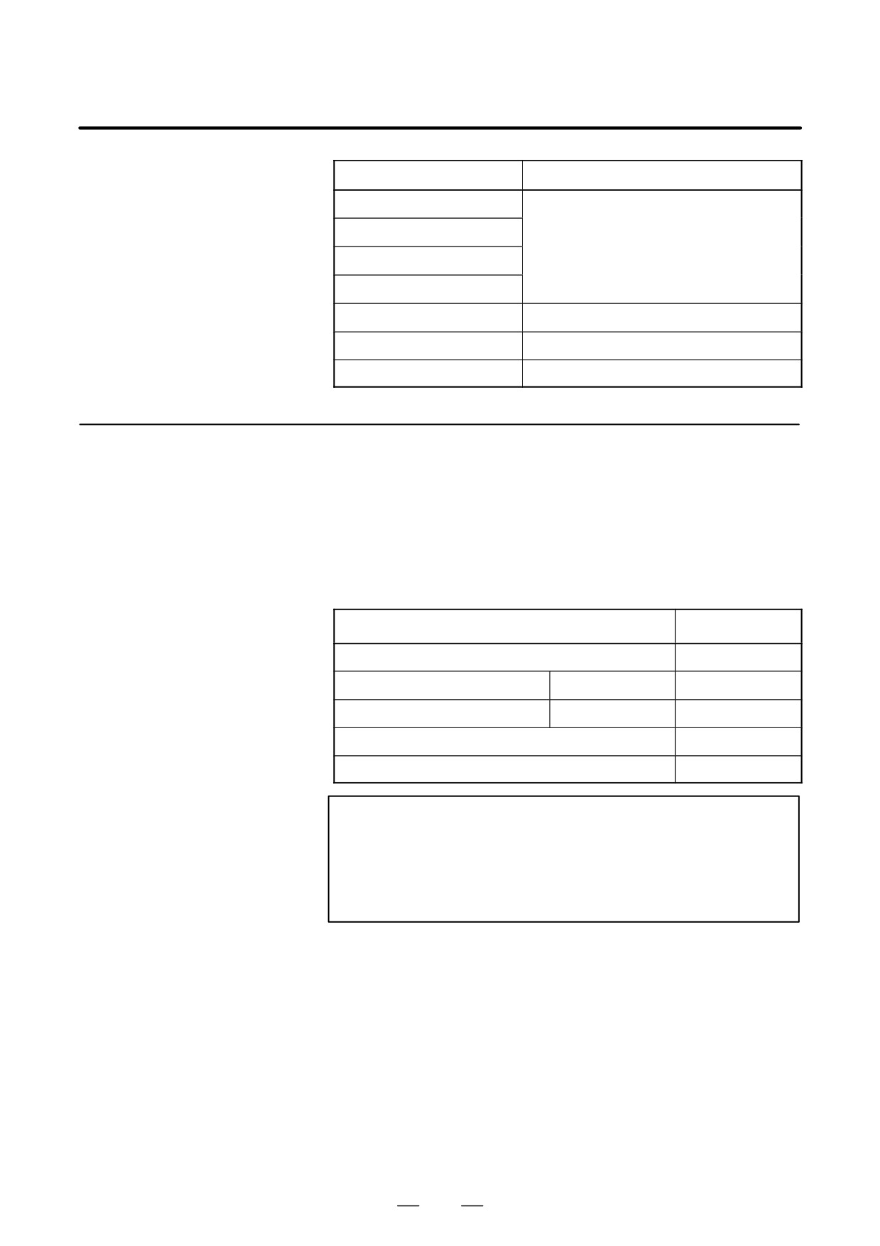
Name
Specification
Inverter
For monochrome LCD
A20B-8100-0710
P.C.B
For 10.4″ color LCD
A20B-8001-0920
For 8.4″ color LCD
A20B-8001-0922
Connector
For unit with no option slot
A15L-0001-0060#B
unit
For unit with two option slots
A15L-0001-0060#A
For unit with three or four option slots
A15L-0001-0060#C
NOTE
The connector unit is fastened to the case with self-tapping
screws.
184
2. LCD-MOUNTED TYPE i SERIES
B-63525EN/02
HARDWARE
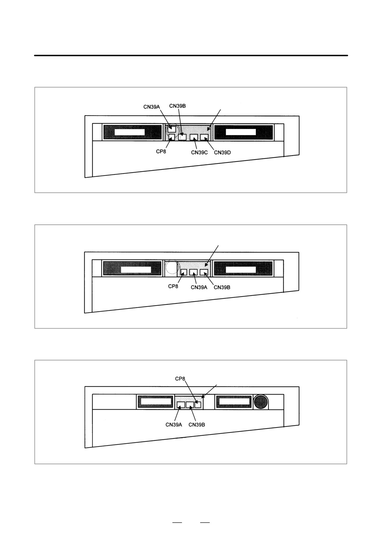
D Connector mounting
(1) With 3 or 4 slots
location
Connector unit
Fan motor
Fan motor
Rear of unit
(2) With 2 slots
Connector unit
Fan motor
Fan motor
Rear of unit
(3) With no slot
Connector unit
Fan motor
Fan motor
Battery
Rear of unit
185
2. LCD-MOUNTED TYPE i SERIES
HARDWARE
B-63525EN/02
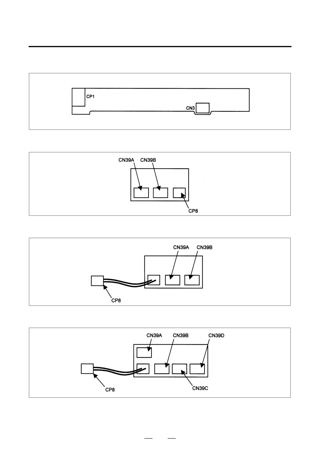
D Connector location
(1) Inverter PCB
(printed-circuit board)
(2) Connector unit for no slot type
(3) Connector unit for 2-slot type
(4) Connector unit for 3-slot and 4-slot types
186
2. LCD-MOUNTED TYPE i SERIES
B-63525EN/02
HARDWARE
Connector number
Application
CN39A
Power supply for fans
CN39B
CN39C
CN39D
CP8
Battery
CP1
Power supply for LCD backlight
CN3
Power supply for inverter PCB
2.4.3
C Board, Serial
Communication Board,
Symbol CAPi T Board,
and PMC-RE Board
D Specification
Name
Specification
C board
A20B-8100-0261
Serial communication board A
Remote buffer/DNC2
A20B-8100-0262
Serial communication board B
DNC1
A20B-8100-0263
Symbol CAPi T board
A20B-8100-0264
PMC-RE board
A20B-8100-0150
NOTE
The PMC-RE board cannot fit into any of the following slots.
· Center slot of a unit with 3 option slots
· Option slot farthest from the LCD in a unit with 4 option
slots
187
2. LCD-MOUNTED TYPE i SERIES
HARDWARE
B-63525EN/02
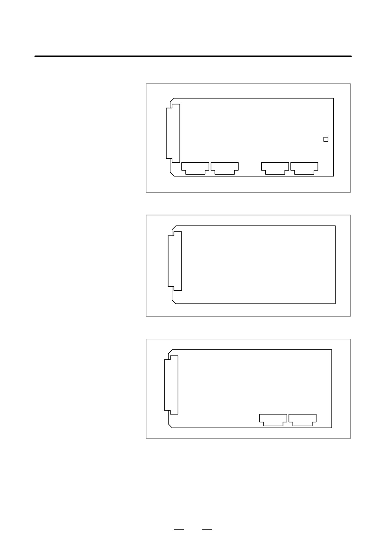
D Connector location
(1) PMC-RE board
JNA
F-BUS backplane connector
CP8B
JD1A2
JD38B
JD38A
JD6A
(2) C board
JNA
F-BUS backplane connector
(3) Serial communication board A remote buffer/DNC2
JNA
F-BUS backplane connector
JD28A
JD6A
188
2. LCD-MOUNTED TYPE i SERIES
B-63525EN/02
HARDWARE
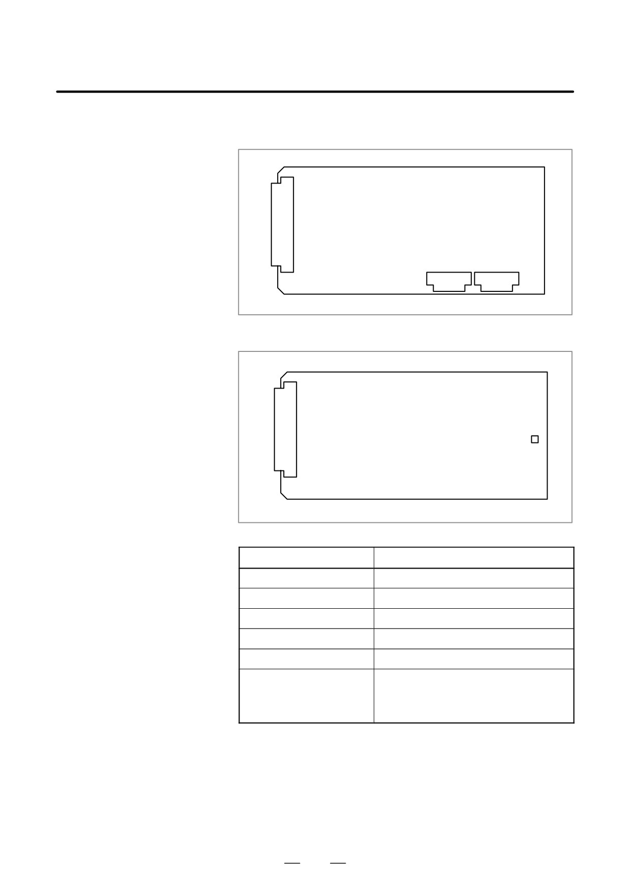
(4) Serial communication board B
DNC1
JNA
F-BUS backplane connector
JD28A
JD6A
(5) CAP-II board/Symbol CAPi T board
JNA
F-BUS backplane connector
CP8B
Connector number
Application
JD1A2
I/O link
JD38B
RS-232C serial port
JD38A
RS-232C serial port
JD28A
RS-232C serial port
JD6A
RS-422 serial port
CP8B
SRAM backup battery
(Normally, the connector is not used. To keep the
contents of SRAM with the printed circuit board re-
moved, connect the battery to this connector.)
189
2. LCD-MOUNTED TYPE i SERIES
HARDWARE
B-63525EN/02
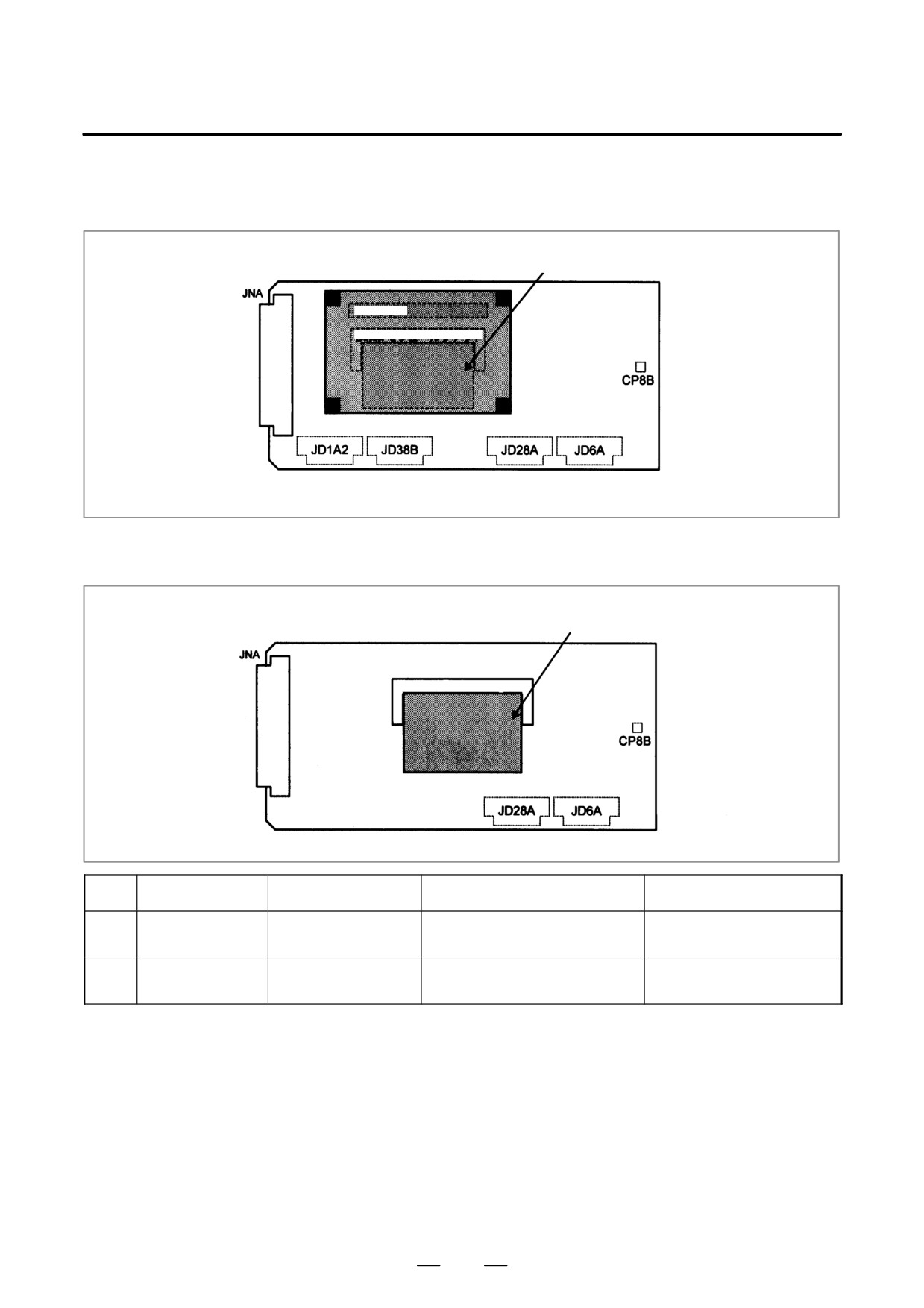
D Card and DIMM module
PMC-RE board
locations
(2)
(1)
DRAM module
CPU card
Connector
DIMM module socket
Note) The DRAM module is mounted on the CPU card.
C language board, serial communication board, Symbol CAPi T board
(2)
DRAM module
DIMM module socket
No.
Name
Specification
Function
Remarks
(1)
CPU card
A20B-3300-0070
PMC/communication/
conversational function
(2)
DRAM module
A20B-3900-0042
DRAM for PMC/communication/
4M/2M
conversational function
190
2. LCD-MOUNTED TYPE i SERIES
B-63525EN/02
HARDWARE
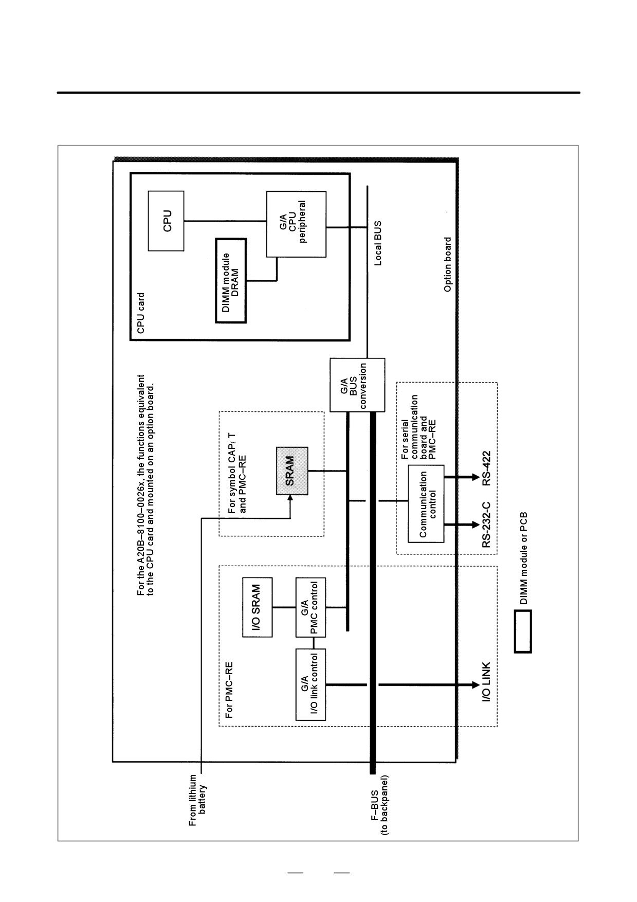
D Block diagram
191
2. LCD-MOUNTED TYPE i SERIES
HARDWARE
B-63525EN/02
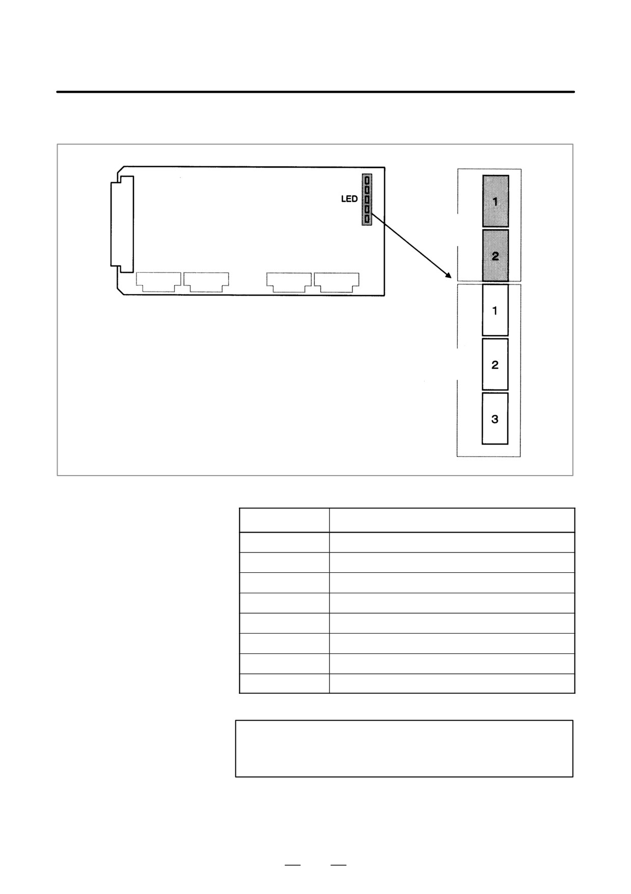
D LED indication
Status
(green)
Alarm
(red)
Alarm LED (red) indication at system alarm occurrence
Alarm: 1 2 3
Cause
jjj
Usual operation under way
Jjj
Bus error (L-bus alarm)
jJj
Bus error or DRAM parity (L-bus EMG)
JJj
Reset under way
jjJ
I/O link error
JjJ
(Reserved)
jJJ
SRAM parity
JJJ
I/O SRAM parity
J: On j: Off
NOTE
The alarm LED indicates that a reset is under way
immediately after the power is turned on.
192
2. LCD-MOUNTED TYPE i SERIES
B-63525EN/02
HARDWARE
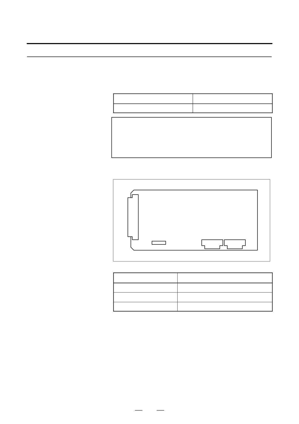
2.4.4
Sub-CPU Board
D Specification
Name7
Specification
Sub-CPU board
A20B-8002-0190
NOTE
The sub-CPU board cannot fit into any of the following slots.
· Center slot of a unit with 3 option slots
· Option slot farthest from the LCD in a unit with 4 option
slots
D Connector mounting
location
JNA
F-bus backplane connector
JA41
JA40
CA69
Connector number
Application
CA69
Servo check
JA41
Serial spindle/position coder
JA40
Analog output
193
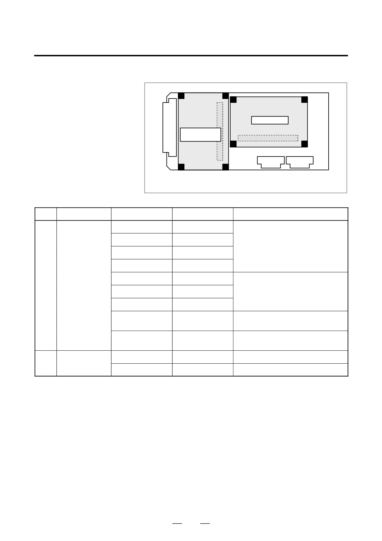
2. LCD-MOUNTED TYPE i SERIES
HARDWARE
B-63525EN/02
D Card and DIMM module
locations
Connector
(2) CPU card
(1) Axis control
Connector
card
The DRAM module is mounted on the CPU card.
No.
Name
Specification
Function
Remarks
(1)
Axis control card
A20B-3300-0243
Axis control 2 axes
Applicable servo software:
Series 90B0
A20B-3300-0242
Axis control 4 axes
A20B-3300-0241
Axis control 6 axes
A20B-3300-0240
Axis control 8 axes
A20B-3300-0248
Axis control 4 axes
Applicable servo software:
Series 90B0 (High-speed HRV)
A20B-3300-0245
Axis control 6 axes
A20B-3300-0244
Axis control 8 axes
A20B-3300-0246
Learning-control axis
Applicable servo software:
control
Series 90B3/90B7
A20B-3300-0247
Learning-control axis
Applicable servo software:
control
Series 90B3/90B7 (High-speed HRV)
(2)
CPU card
A20B-3300-0310
DRAM 16MB
A20B-3300-0311
DRAM 32MB
194
2. LCD-MOUNTED TYPE i SERIES
B-63525EN/02
HARDWARE
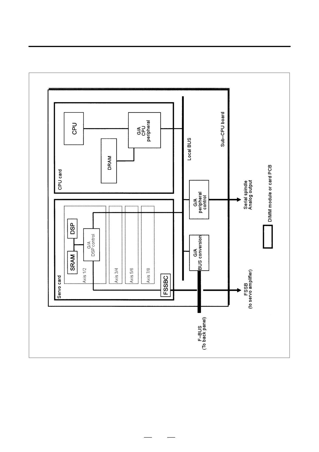
D Block diagram
195
2. LCD-MOUNTED TYPE i SERIES
HARDWARE
B-63525EN/02
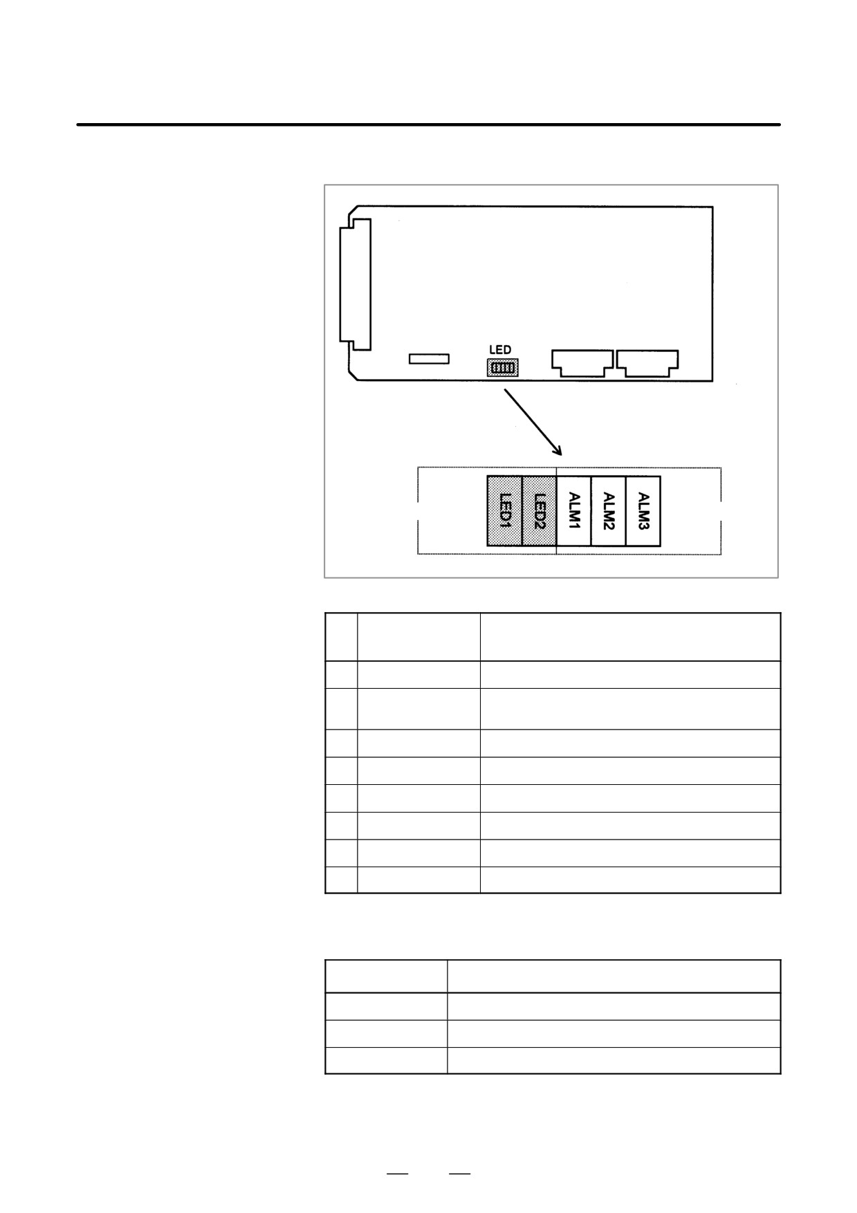
D LED indication
Status (green)
Alarm (red)
(1) Changes in status LED (green) indication at power-on time
Status LED
No.
Status
(LED1, 2)
1
jj
Power is not supplied.
2
JJ
Initial status immediately after power is switched on; the
sub-CPU has not started.
3
jJ
RAMinitialization.
4
Jj
Waiting for system ID to be set up.
5
jj
Waiting for software initialization to be completed No. 1
6
JJ
Waiting for software initialization to be completed No. 2
7
jJ
Initialization of position coder, digital servo circuit, etc.
8
Jj
Initialization completed, and usual operation under way
J: On j: Off
(2) Alarm LED (red) indication at system alarm occurrence
Alarm LED
Meaning
ALM1
Bus error on sub-CPU board.
ALM2
Servo alarm.
ALM3
Bus error on other than sub-CPU board (F-BUS).
196
2. LCD-MOUNTED TYPE i SERIES
B-63525EN/02
HARDWARE
2.4.5
RISC Board
D Specification
Name
Specification
RISC board
A20B-8100-0170
NOTE
The RISC board cannot fit into any of the following slots.
· Center slot of a unit with 3 option slots
· Option slot farthest from the LCD in a unit with 4 option
slots
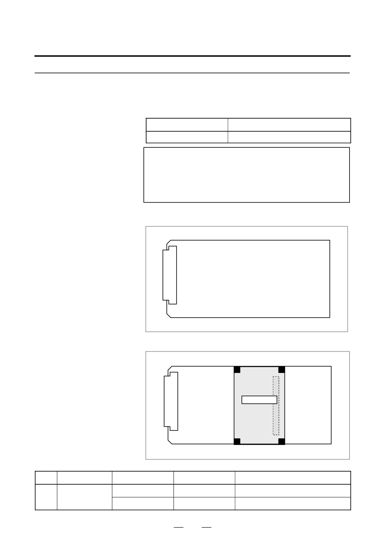
D Connector mounting
location
JNA
F-bus backplane connector
D Card mounting location
Connector
(1) CPU card
No.
Name
Specification
Function
Remarks
(1)
CPU card
A20B-3300-0102
Standard type
A17B-3300-0400
High-speed type
197
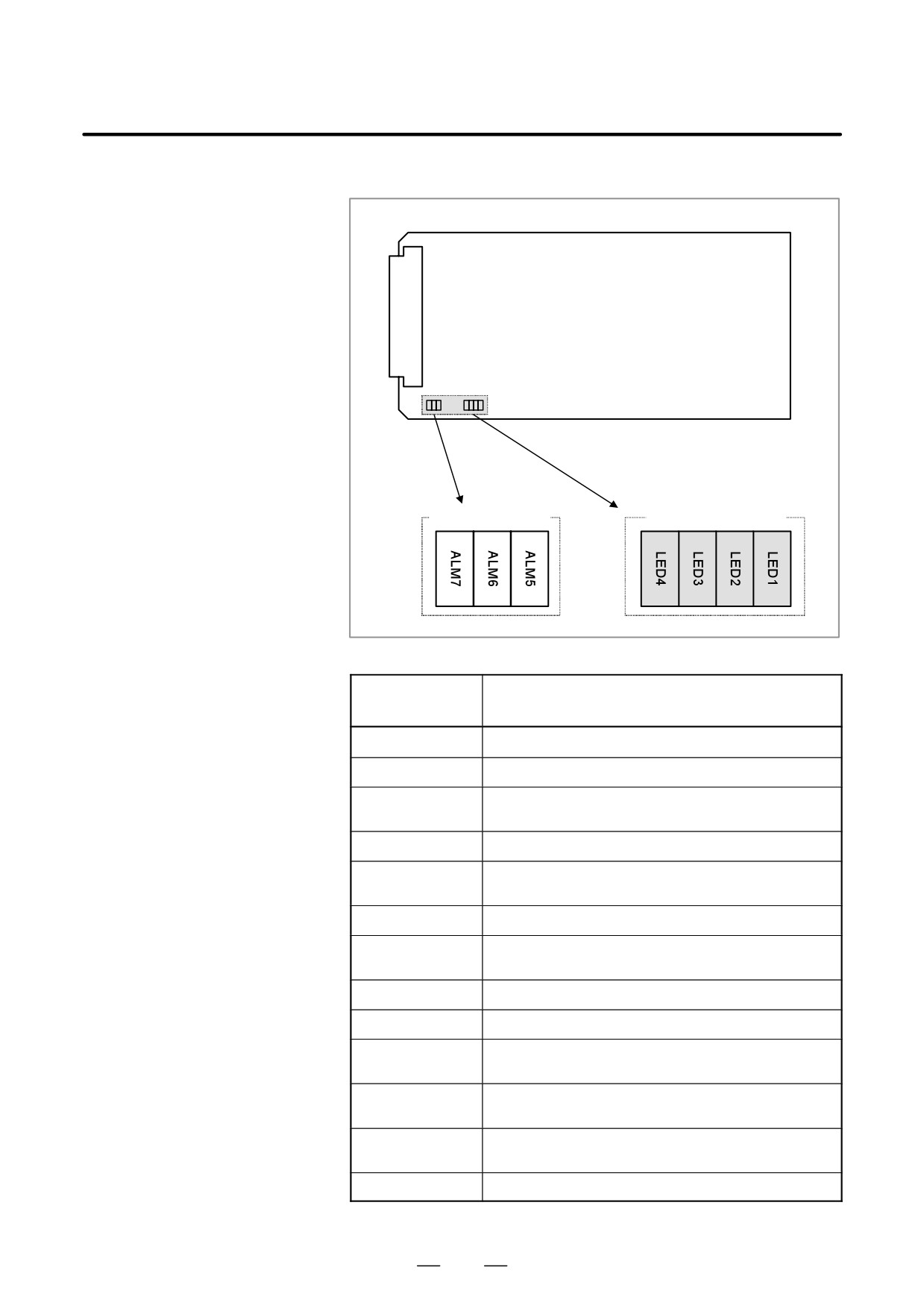
2. LCD-MOUNTED TYPE i SERIES
HARDWARE
B-63525EN/02
D LED indication
Alarm (red)
Status (green)
(1) Status LED (green) indication (LED lighting)
Alarm LED
Status
(LED4 to LED1)
jjjj
Power is not supplied.
Jjjj
CNC wait (1) (Check the CNC for the cause.)
Module ID error (Replace the printed circuit board or FROM
jJjj
module.)
JJjj
CNC wait (5) (Check the CNC for the cause.)
ROM test error (Replace the printed circuit board or FROM
jjJj
module.)
JjJj
CNC wait (3) (Check the CNC for the cause.)
System error (Replace the printed circuit board or FROM mod-
JJJj
ule.)
jjjJ
RAM test error (Replace the printed circuit board.)
JjjJ
CNC wait (2) (Check the CNC for the cause.)
Parameter error (Replace the printed circuit board or FROM
jJjJ
module.) (B437 Series only)
DRAM test error, interpolation cycle interrupt wait (Replace the
jjJJ
printed circuit board.)
CNC wait (4) (Check the CNC for the cause.) (B451 Series
JjJJ
only)
JJJJ
Power was turned on, but the processor is not activated.
J: On j: Off
198
2. LCD-MOUNTED TYPE i SERIES
B-63525EN/02
HARDWARE
(2) Status LED (green) indication (LED blinking)
Alarm LED
Status
(LED4 to LED1)
Ljjj
Command execution in progress (reset)
jLLj
Command execution in progress (pre-processing, distribution)
jjjL
Command wait
jLjL
NC statement input wait
LLjL
Command execution in progress (parameter change) (B437
Series only)
jjLL
Automatic operation is not activated. (Replace the printed cir-
cuit board.) (B451 Series only)
L: Blinking j: Off
(3) Alarm LED (red) indication
Alarm LED
Status
(LED7 to LED6)
Jjj
DRAM parity error occurred.
jJj
Something unusual occurred in the power for the processor
core.
jjJ
Reserved
J: On j: Off
199
2. LCD-MOUNTED TYPE i SERIES
HARDWARE
B-63525EN/02
2.4.6
Data Server Board
D Specification
Name
Specification
Data server board
A20B-8100-0271
(ATA card version)
Add-on board
A20B-2002-0960
NOTE
The data server board (ATA card version) cannot fit into any
of the following slots.
· Option slot nearest to the LCD
· Center slot of a unit with 3 option slots
· Option slot farthest from the LCD in a unit with 4 option
slots
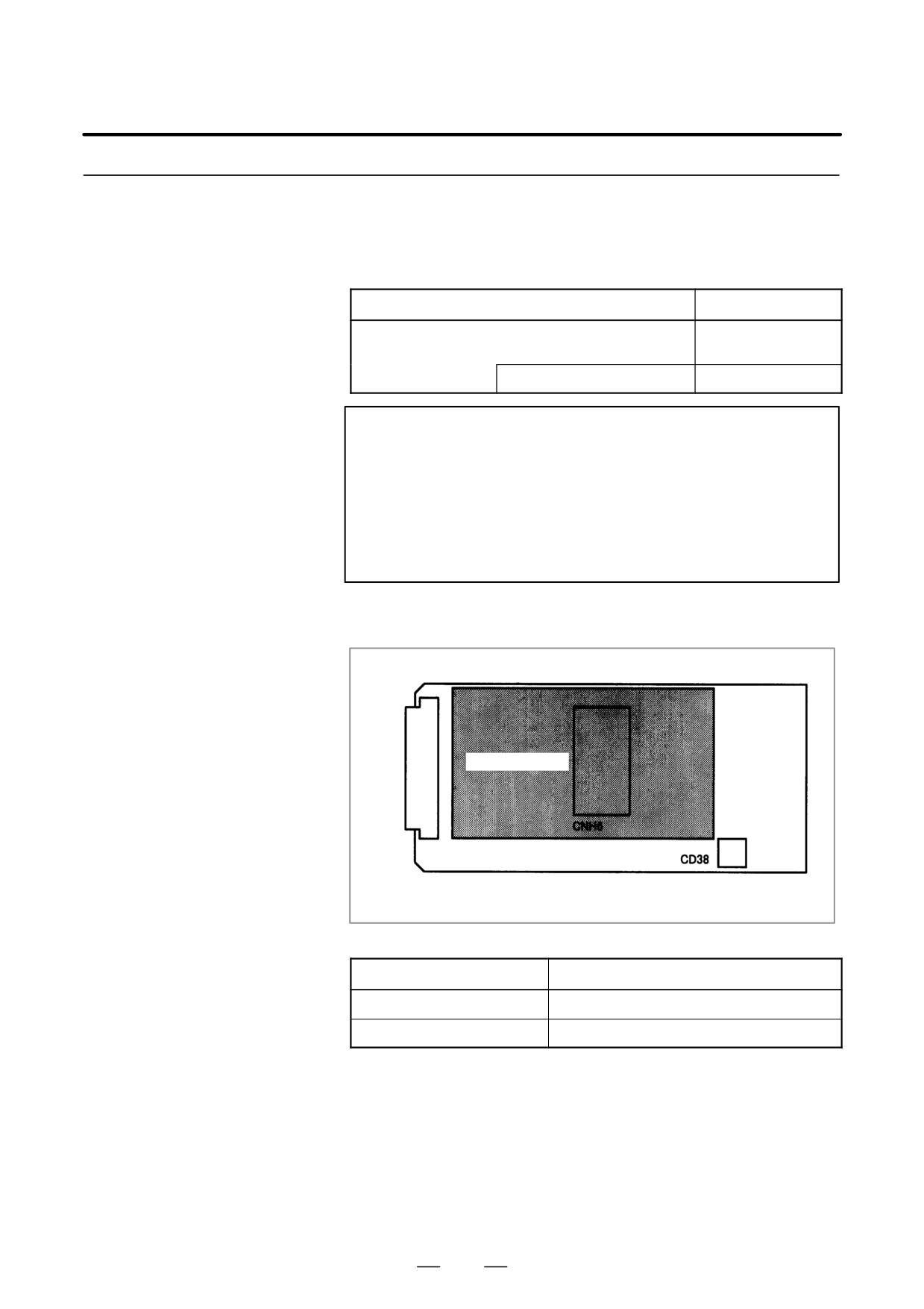
D Connector mounting
location
F-BUS backplane connector
JNA
Add-on board
CNH6 is mounted on the add-on board.
Connector number
Application
CNH6
ATA card interface
CD38
10BASE-T Ethernet interface
200
2. LCD-MOUNTED TYPE i SERIES
B-63525EN/02
HARDWARE
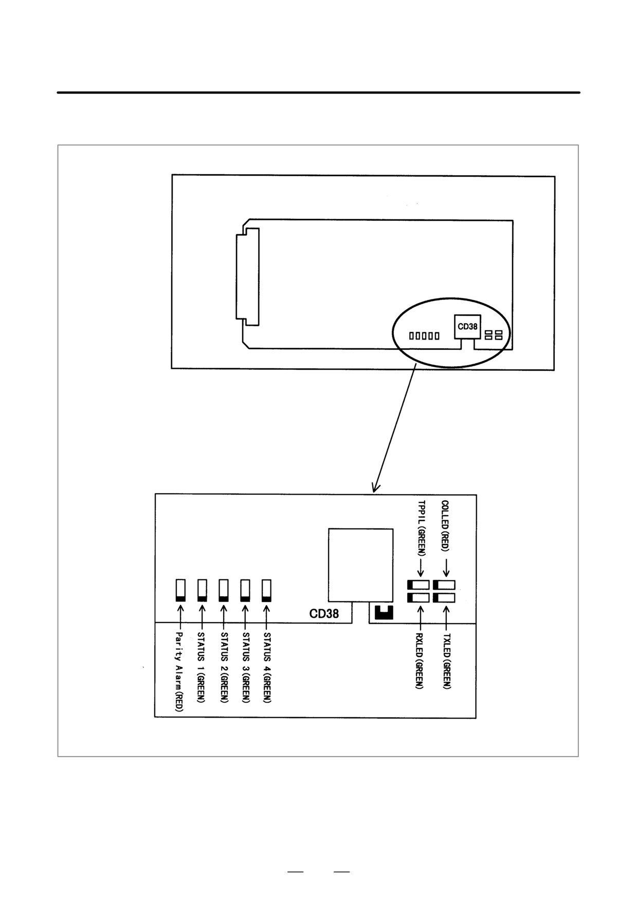
D LED indication
JNA
F-BUS backplane connector
LED detail diagram
201
2.
LCD-MOUNTED TYPE i SERIES
HARDWARE
B-63525EN/02
LED indication transition at power-on time
LED indication
No.
Ethernet board status
1234
1
STATUS jjjj
Power off.
2
STATUS JJJJ
Initial status immediately after power is switched on.
3
STATUS jJJJ
MPU initialization completed.
4
STATUS jjJJ
Firmware download completed.
5
STATUS jjjJ
Control passed to the OS.
6
STATUS JJJj
OS PHASE 1
7
STATUS jJJj
OS PHASE 2
8
STATUS JjJj
OS PHASE 3
9
STATUS jjJj
OS PHASE 4
10
STATUS ljjj
Start sequence completed.
When the Ethernet board is started normally, the STATUS LEDs light as
shown at No. 10. This condition is preserved unless an abnormal
condition occurs.
Communication status LED indication
No.
LED indication
Ethernet communication status
1
RXLED
J
Lights during data reception.
2
TXLED
J
Lights during data transmission.
3
TPPIL
J
Lights to indicate normal connection with the hub.
4
COLLED
J
Lights to indicate a data collision.
NOTE
TPPIL: If this LED is off, communication does not occur.
It is likely that the Ethernet board is not
connected with the hub normally. The LED does
not light also when the power to the hub is off. It
remains to be on when the Ethernet board is
connected to the hub normally.
COLLED: This LED lights frequently if Ethernet
communication
traffic
(amount
of
communication) is heavy or noise in the
surrounding is high.
202
2. LCD-MOUNTED TYPE i SERIES
B-63525EN/02
HARDWARE
LED indication (STATUS) at error occurrence
The STATUS LEDs repeat LONG and SHORT patterns. The LONG and
SHORT patterns correspond to long and short lighting intervals,
respectively.
STATUS LED
indication
No.
Ethernet/data server board state
LONG
SHORT
1234
1234
1
jjjJ
Jjjj
Failure caused by this
System reset
board.
2
jjjJ
jJjj
Machine check
3
jjJJ
Jjjj
DRAM parity alarm
4
jjJJ
jJjj
Failure caused by anoth-
NMI of another module
er board.
NOTE
If an error, indicated by repeatedly flashing a LONG and
SHORT combination other than the above, occurs, contact
FANUC.
LED indication (ALARM) at error occurrence
No.
LED indication
Ethernet board status
1
Parity Alarm
J
A parity error has occurred in main memory.
It is likely that the hardware is defective.
203
2. LCD-MOUNTED TYPE i SERIES
HARDWARE
B-63525EN/02
2.4.7
Loader Control Board
D Specification
Name
Specification
Loader control board
A20B-8100-0830
NOTE
The loader control board cannot fit into any of the following
slots.
· Center slot of a unit with 3 option slots
· Option slot farthest from the LCD in a unit with 4 option
slots
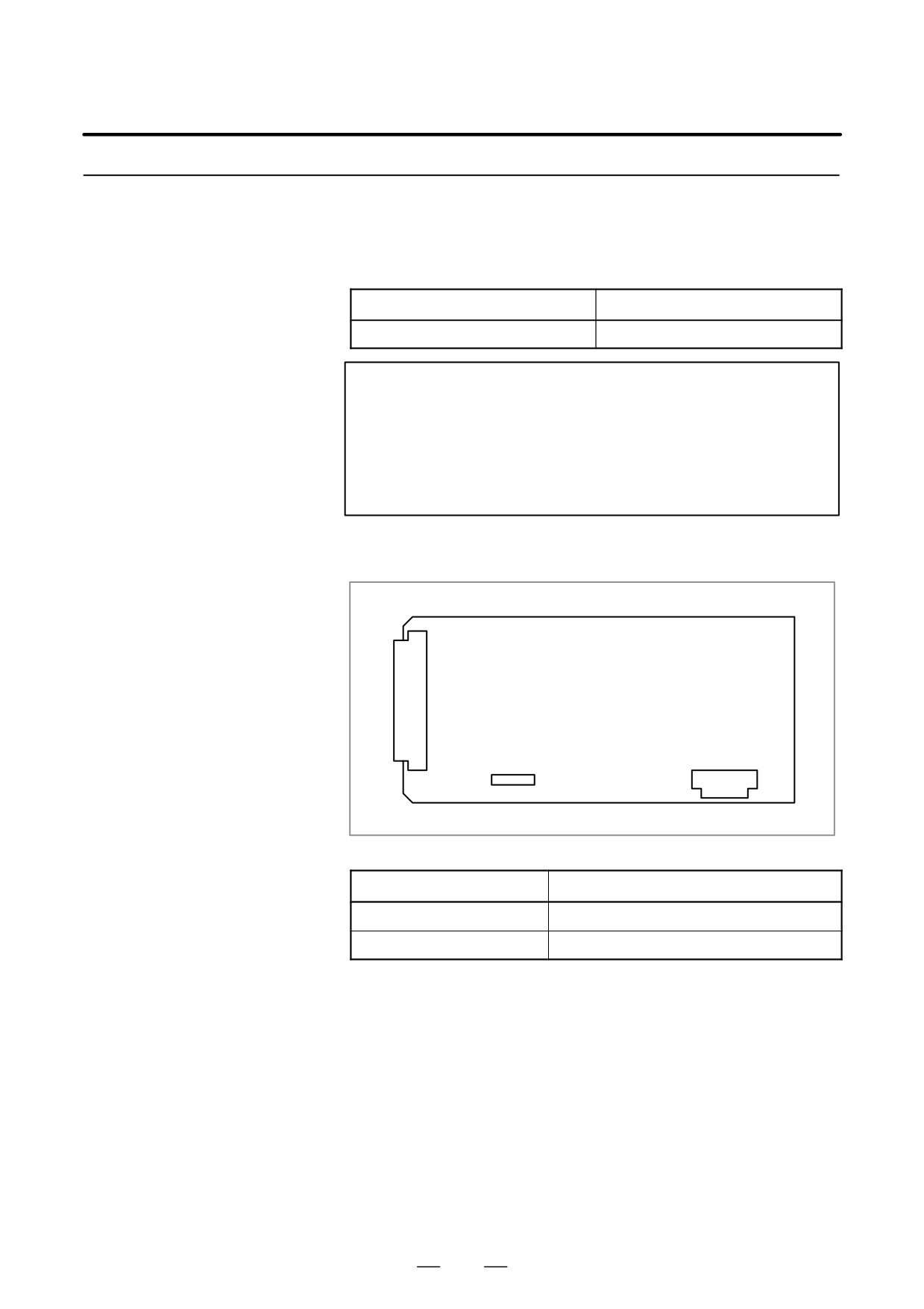
D Connector mounting
location
JNA
F-bus backplane connector
JD1A
CA69
Connector number
Application
CA69
Servo check
JD1A
I/O link
204
2. LCD-MOUNTED TYPE i SERIES
B-63525EN/02
HARDWARE
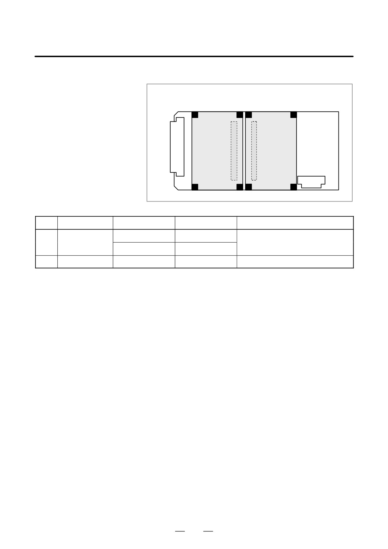
D Card mounting location
(1)
(2)
Axis control card
CPU card
JNA
Connector
Connector
JD1A
No.
Name
Specification
Function
Remarks
(1)
Axis control card
A20B-3300-0033
Axis control 2 axes
Applicable servo software: Series 9090
A20B-3300-0032
Axis control 4 axes
(2)
CPU card
A20B-3300-0291
With DRAM 16MB
205
2. LCD-MOUNTED TYPE i SERIES
HARDWARE
B-63525EN/02
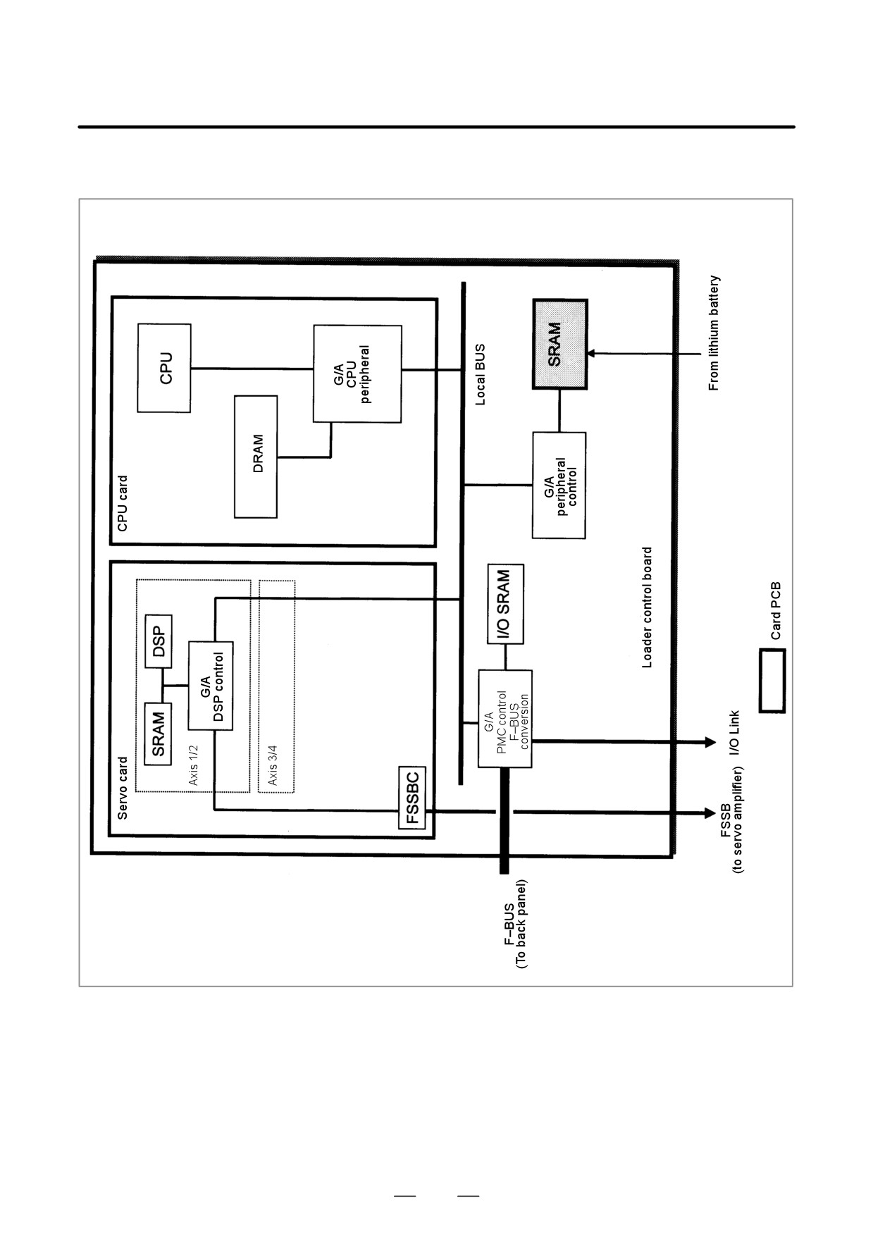
D Block diagram
206
2. LCD-MOUNTED TYPE i SERIES
B-63525EN/02
HARDWARE
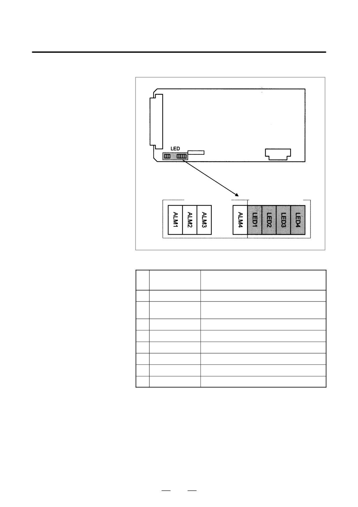
D LED indication
Alarm (red)
Status (green)
(1) Changes in status LED (green) indication at power-on time
Status LED
No.
Status
(LED1 to 4)
1
jjjj
Power is not supplied.
2
JJJJ
Initial status immediately after power is switched on; the
loader CPU has not started.
3
JJJj
RAMinitialization
4
JJjJ
Waiting for system ID to be set up.
5
JJjj
Waiting for software initialization to be completed No. 1
6
JjJJ
Waiting for software initialization to be completed No. 2
7
jJJj
Waiting for digital servo to be initialized.
9
jjjJ
Initialization completed, and usual operation under way.
J: On j: Off
207
2. LCD-MOUNTED TYPE i SERIES
HARDWARE
B-63525EN/02
(2) Alarm LED (red) indication at system alarm occurrence
When any of these alarm LEDs lights, it is likely that the hardware is
defective.
Alarm LED
Meaning
ALM1
SRAM parity alarm.
ALM2
Servo alarm.
ALM3
Lights when a system alarm occurs.
Used by the software to stop the system.
ALM4
Lights when a system alarm occurs.
The hardware has detected a failure in the system.
2.4.8
HSSB Interface Board
D Specification
Name
Specification
HSSB interface board
A20B-8001-0641
D Connector mounting
location
JNA
F-bus backplane connector
COP7
Connector number
Application
COP7
High-speed serial bus interface
D Card mounting location
No card is mounted on the HSSB interface board.
208
2. LCD-MOUNTED TYPE i SERIES
B-63525EN/02
HARDWARE
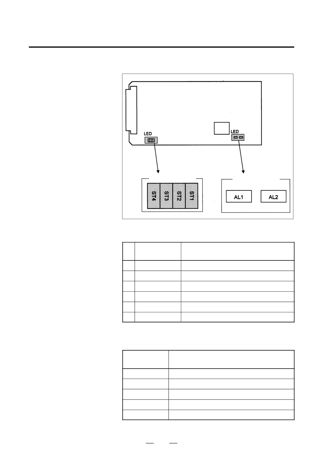
D LED indication
Status (green)
Alarm (red)
(1) Changes in status LED (green) indication at power-on time
Status LED
No.
Status
(ST4 to 1)
1
jjjj
Power is not supplied.
2
JJJJ
Initial status immediately after power is switched on.
3
JJJj
HSSB board being initialized.
4
JJjJ
Waiting for PC boot to be executed.
5
JJjj
CNC screen being displayed on the PC.
6
Jjjj
Initialization completed, and usual operation under way.
J: On j: Off
(2) Status LED (PC status, green) indication at error occurrence
Status LED
Status
(ST4 to 1)
jJJj
A thermal error has occurred at the PANEL i.
jJjJ
HSSB communication was discontinued.
jJjj
Parity alarm in NC/PC common RAM.
jjJJ
An HSSB communication error has occurred.
jjJj
A battery alarm has occurred at the PANEL i.
J: On j: Off
209
2. LCD-MOUNTED TYPE i SERIES
HARDWARE
B-63525EN/02
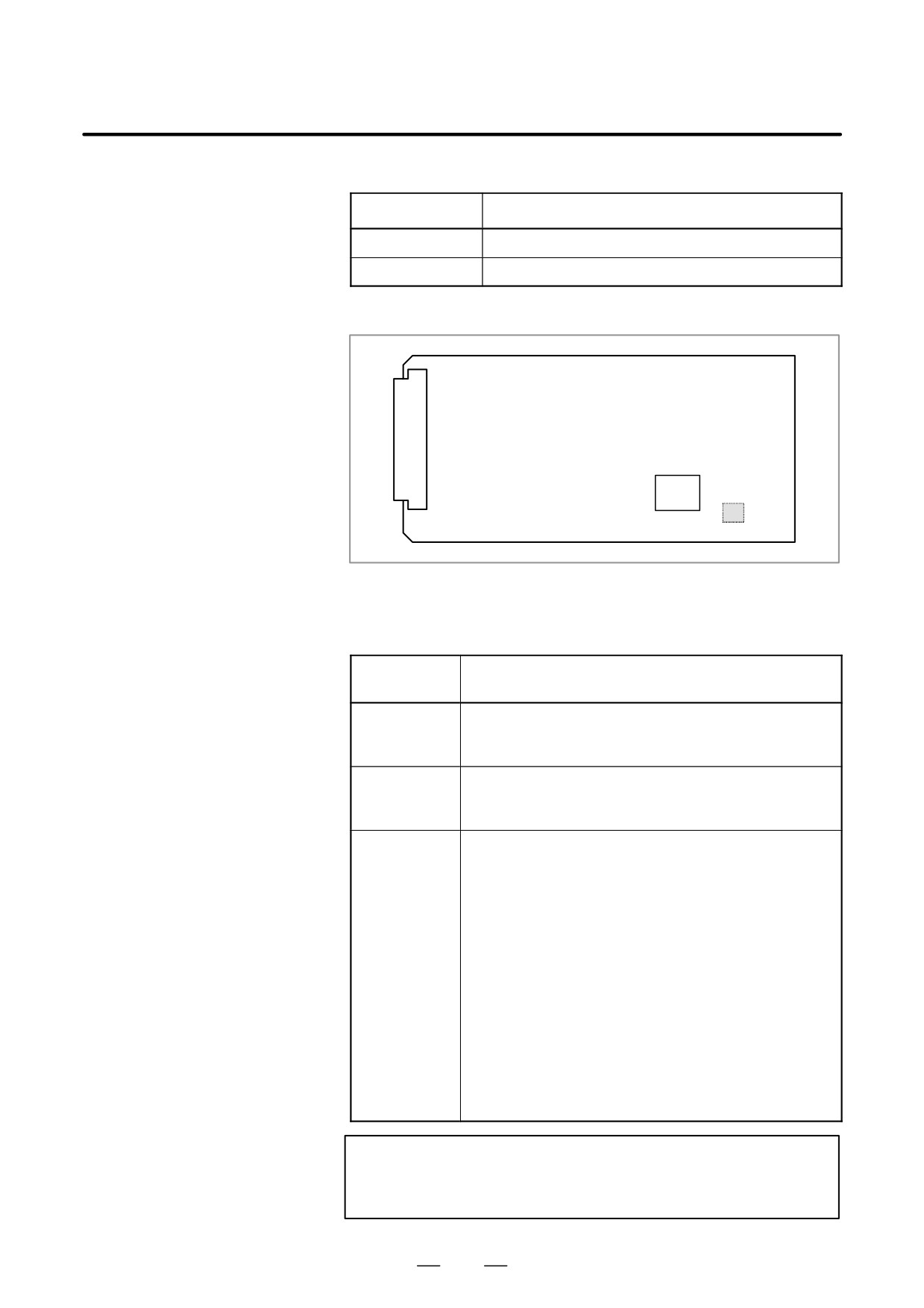
(3) Alarm LED (red) indication at error occurrence
Alarm LED
Meaning
AL1
HSSB communication was discontinued.
AL2
Parity alarm in NC/PC common RAM.
D Rotary switch (SW1)
setting
SW1
Rotary switch setting when the PC or PANEL i is connected
By changing the rotary switch setting on the board, the startup sequence
at power-up can be changed.
Rotary switch
Contents
setting
0
Setting for maintenance.
The start menu is displayed. It is possible to start boot and
IPL from the PC or PANEL i.
1
Setting for usual operation.
The start menu is not displayed.
It is impossible to start boot or IPL from the PC.
2
The CNC and PC or PANEL i do not perform the handshake but
start independently of each other.
D CNC
Even if the PC is not connected or turned on, just the CNC can
be started and operated. (For this operation, a special display
unit, MDI, operator’s panel, and the like are necessary.) Even if
the PC or PANEL i is connected and turned on, the startup
menu does not appear.
D PC or PANEL i
Even if the CNC is connected or turned on, the startup menu
does not appear. The boot or IPL operation cannot be performed
from the PC or PANEL i.
If an HSSB device driver for Windows 95/98, WindowsNT4.0, or
Windows2000 is installed on the PC or PANEL i, just the PC or
PANEL i or CNC can be turned on or off.
Formulti-connection, in which multiple CNC units are connected to
a single PC or PANEL i, usually select this setting.
NOTE
PANEL i used here represents hardware that can operate
on a stand-alone basis (provide a stand-alone option).
210
2. LCD-MOUNTED TYPE i SERIES
B-63525EN/02
HARDWARE
2.4.9
I/O Link-II Board
Name
Specification
FANUC I/O Link-II board
A20B-8100-0250
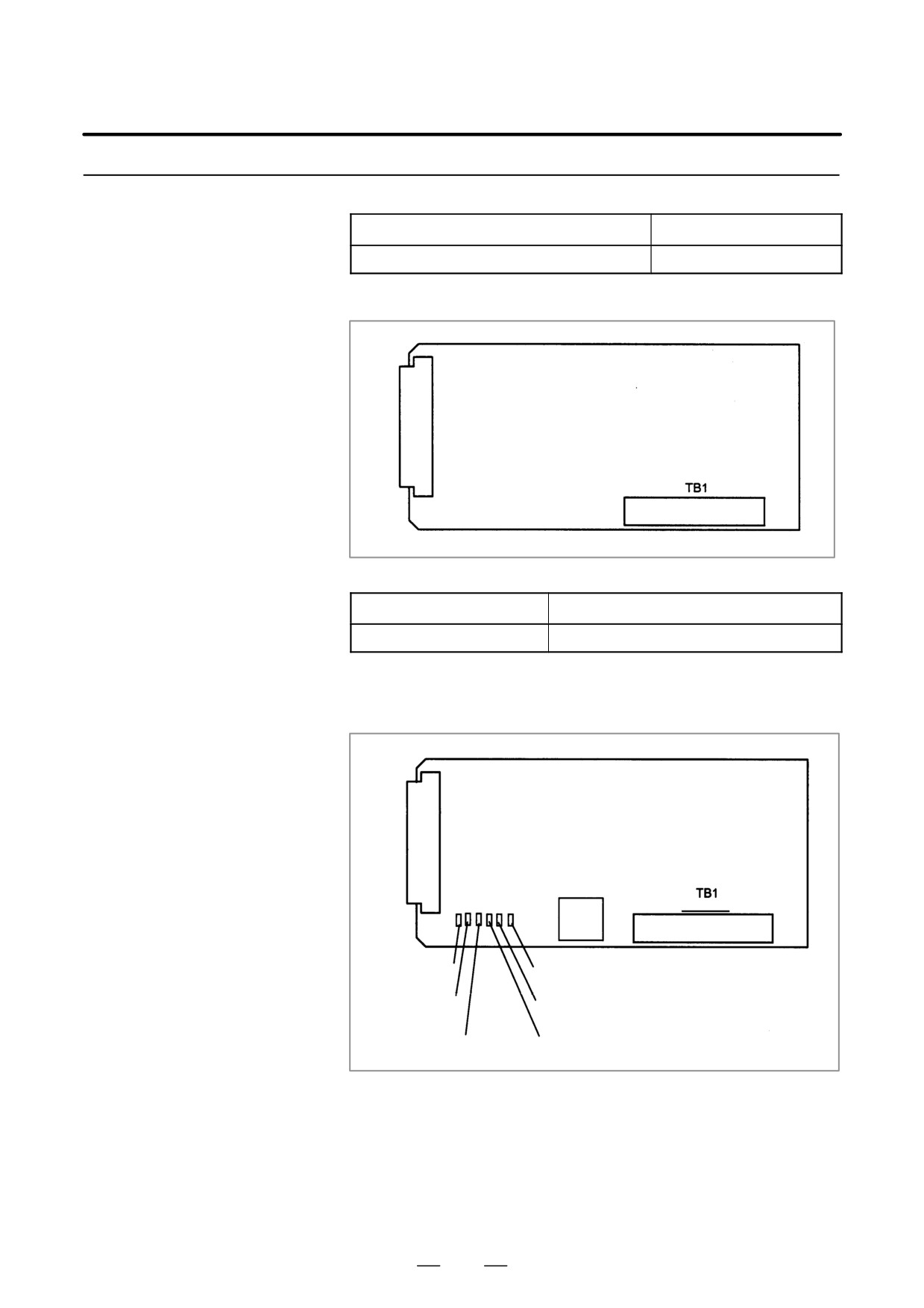
D Connector location
JNA
F-BUS backplane connector
Connector number
Application
TB1
Terminal board for FANUC I/O Link-II interface
D Card location
No card is mounted on the FANUC I/O Link-II board.
D LED indication
SW1
LED6 (red)
LED1 (green)
LED5 (green)
LED2 (green)
LED4 (green)
LED3 (green)
211