FANUC Series 16i/160i/160is-MODEL B, Series 18i/180i/180is-MODEL B, Series 21i/210i/210is-MODEL B. MAINTENANCE MANAUL - page 10
2. LCD-MOUNTED TYPE i SERIES
HARDWARE
B-63525EN/02
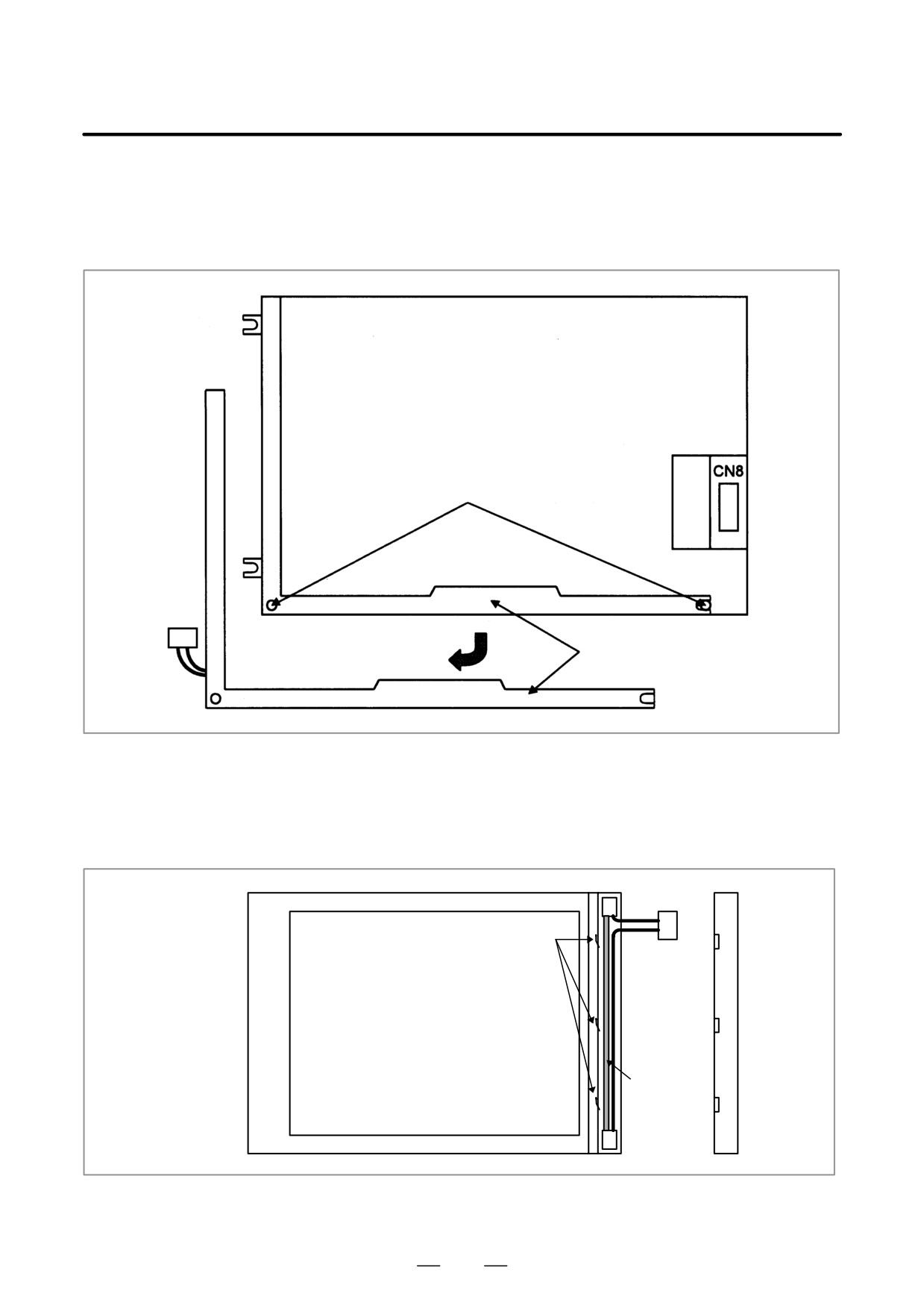
3)-3 For the 8.4″ LCD (color)
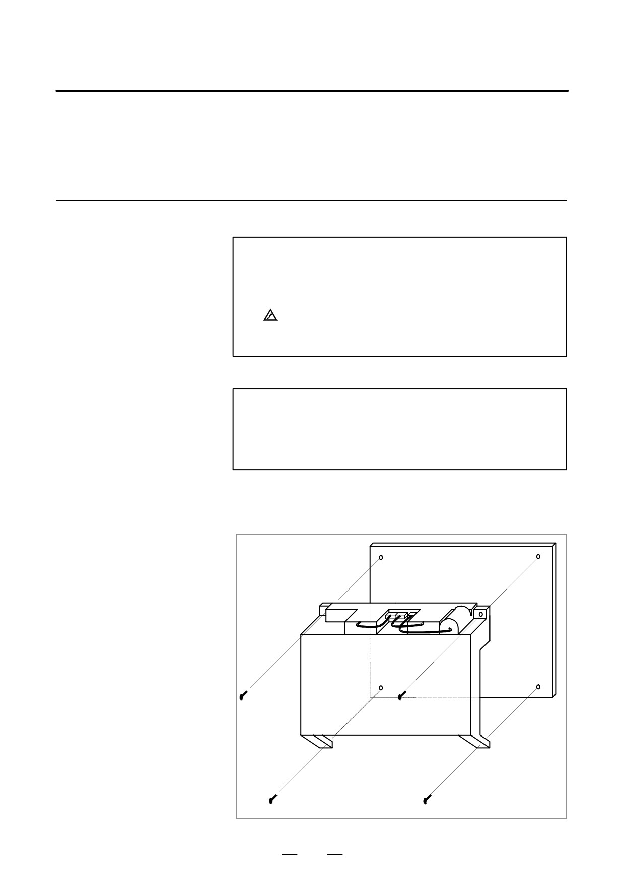
As shown below, remove two bolts, remove the backlight case by
pulling it down and sliding it slightly to the left, then replace the
backlight.
LCD unit rear view
Bolt
Backlight
3)-4 For the 9.5″ LCD units (monochrome)
Remove the three brackets from the left part on the front of the LCD
unit. Remove the cover. The backlight is covered with a sheet. Pull
out the sheet. Then, the backlight is exposed. Replace the backlight
with a new one.
Connector
Bracket
Display surface of LCD unit
Backlight
(After the
sheet is
pulled out)
4) Upon completion of replacement, reassemble the unit by reversing
the steps 1 through 3 above.
242
2. LCD-MOUNTED TYPE i SERIES
B-63525EN/02
HARDWARE
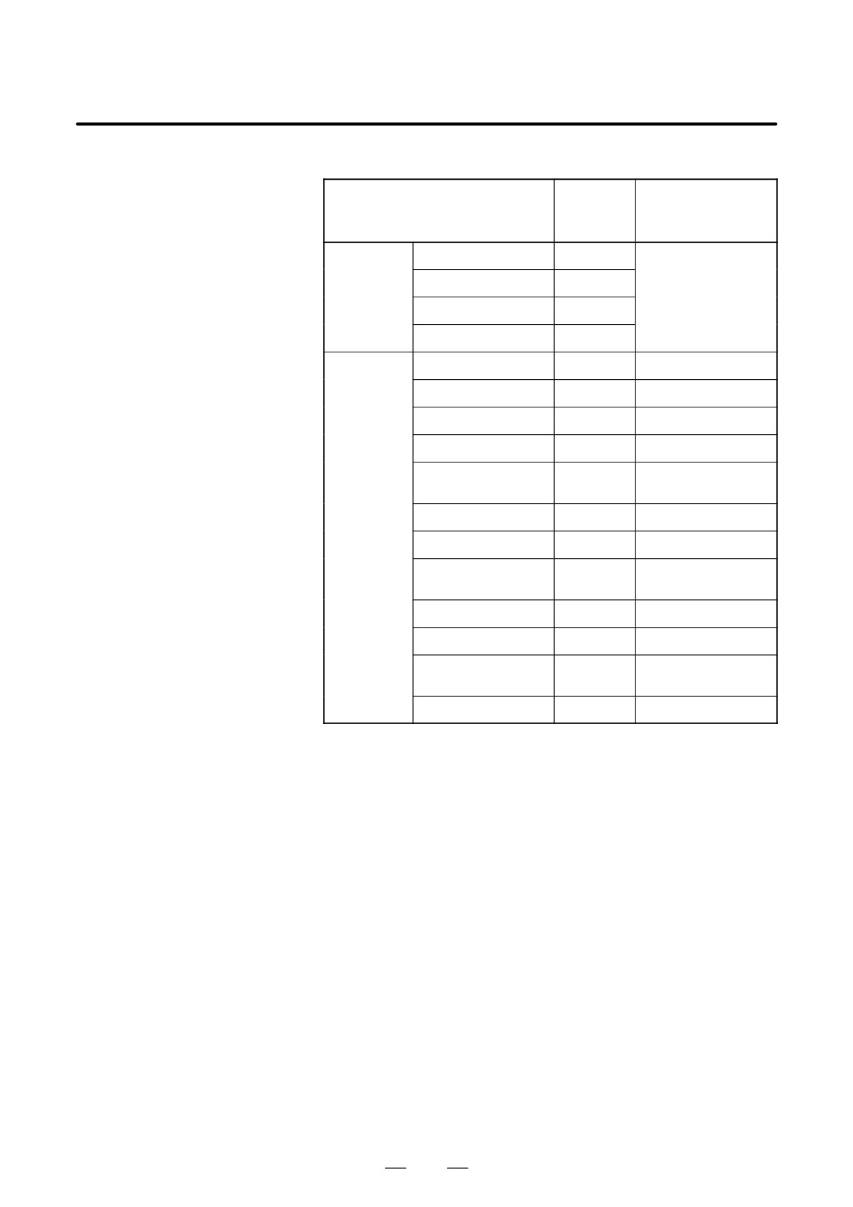
2.11
HEAT GENERATED IN
Amount of
Unit
generated
Remarks
EACH UNIT
heat
Control unit
No option slot
33W
(NOTE 1)
2 option slots
37W
3 option slots
39W
4 option slots
40W
Option boards
HSSB board
3W
Sub-CPU board
13W
Loader control board
10W
PMC C board
5W
Serialcommunication
6W
board
Symbol CAPi T board
10W
RISC board
9W
Data server board
6.3W
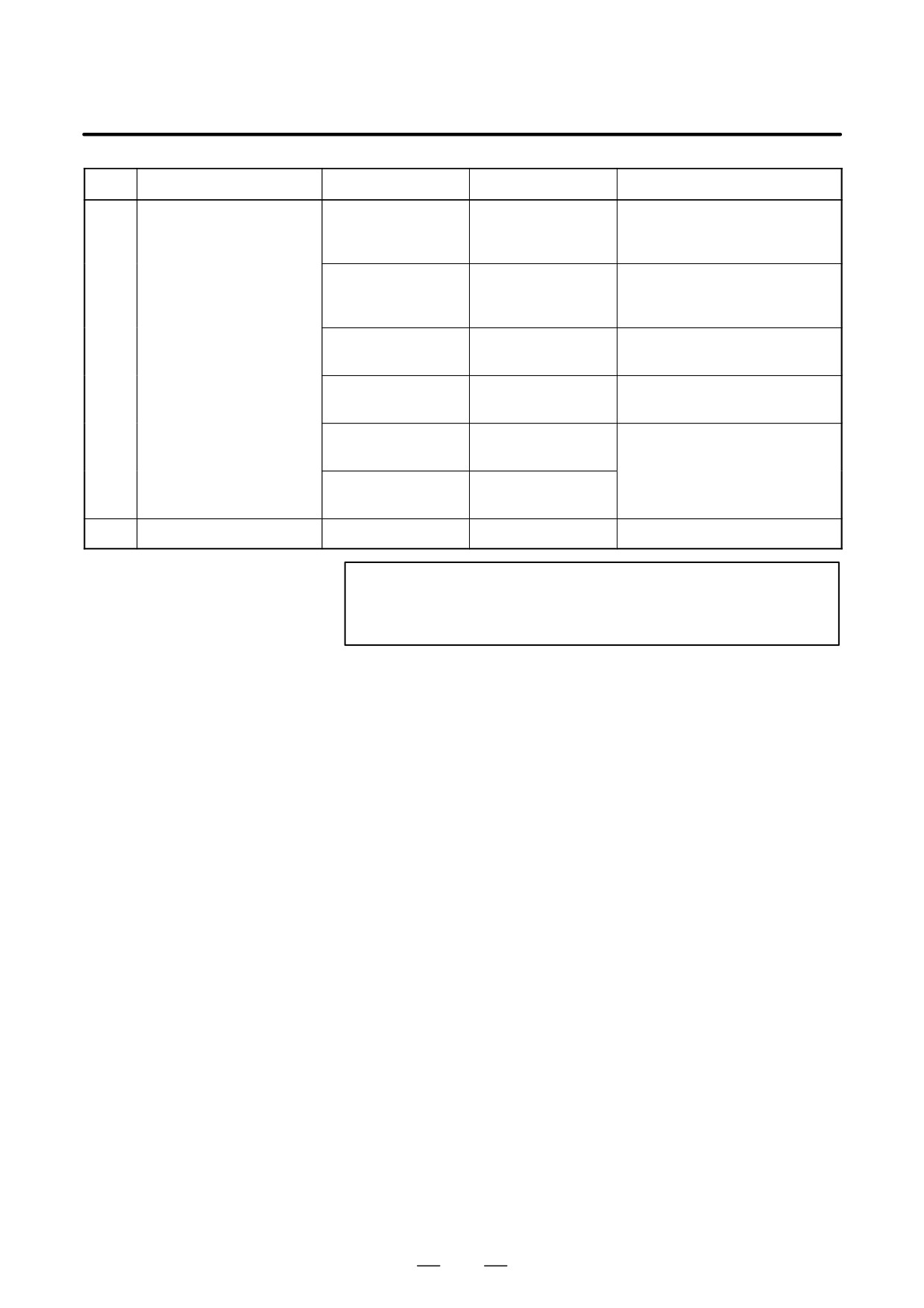
0.3 W generated in ATA
card included (NOTE 4)
I/O link II board
9W
Ethernet board
6W
DeviceNet interface
4W
board
PROFIBUS board
9W
243
2. LCD-MOUNTED TYPE i SERIES
HARDWARE
B-63525EN/02
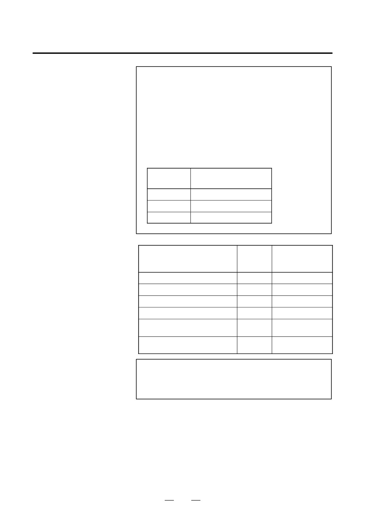
NOTE
1
The amount of heat generated in the LCD and MDI units is
included, but that in each option board is not.
2
The amount of heat generated in the ISA expansion board
varies from one model to another. Add the amount of heat
generated in the ISA board to be used.
3
The amount of heat generated in the ATA flash card may
vary depending on its memory capacity, changes made to
the card specification, and other factors.
4
When using option boards, keep the total amount of heat
generated in the selected option boards to within the
corresponding value listed in the following table.
Total amount of
Option slot
generated heat
2 slots
26W
3 slots
38W
4 slots
38W
Amount of
Remarks
Unit
generated
heat
MDI unit
0W
Operator’s panel I/O module
12W
(NOTE 1)
Connector panel I/O module (basic)
8W
(NOTE 1)
Connector panel I/O module (expansion)
5W
(NOTE 1)
9W
Only for unit with four ba-
Separate detector interface unit
sic axes
14W
Four basic axes and four
Separate detector interface unit
additional axes (NOTE 2)
NOTE
1
This value applies when 50% of the module inputs are on.
2
The amount of heat generated in the separate detector is
not included.
244
B-63525EN/02
3. LCD-MOUNTED TYPE is SERIES HARDWARE
LCD-MOUNTED TYPE is SERIES HARDWARE
3
This chapter describes the LCD-mounted type FS160is/180is/210is
hardware.
See Chapter 4 ”STAND-ALONE TYPE i SERIES HARDWARE,” for
stand-alone type 160is/180is/210is hardware.
3.1
HARDWARE CONFIGURATION
246
3.2
HARDWARE OVERVIEW
246
3.3
TOTAL CONNECTION DIAGRAMS
246
3.4
FS160is/180is/210is MOTHERBOARD
247
3.5
CE CARD
258
3.6
INSTALLING AND REMOVING
OPTIONAL BOARDS
259
3.7
LIST OF UNITS AND PRINTED CIRCUIT
BOARDS
264
3.8
REPLACING THE FUSE ON THE UNITS
265
3.9
REPLACING THE BATTERY
266
3.10 REPLACING THE FAN MOTOR
266
3.11 REPLACING THE LCD BACK-LIGHT
267
3.12 REPLACING THE TOUCH PANEL
PROTECTION SHEET
267
3.13 BACKUP UNIT
268
245
3. LCD-MOUNTED TYPE is SERIES HARDWARE
B-63525EN/02
See section 2.1 for hardware configuration of 160is/180is/210is.
3.1
HARDWARE
CONFIGURATION
See section 2.2 for hardware overview of 160is/180is/210is.
3.2
HARDWARE
OVERVIEW
3.3
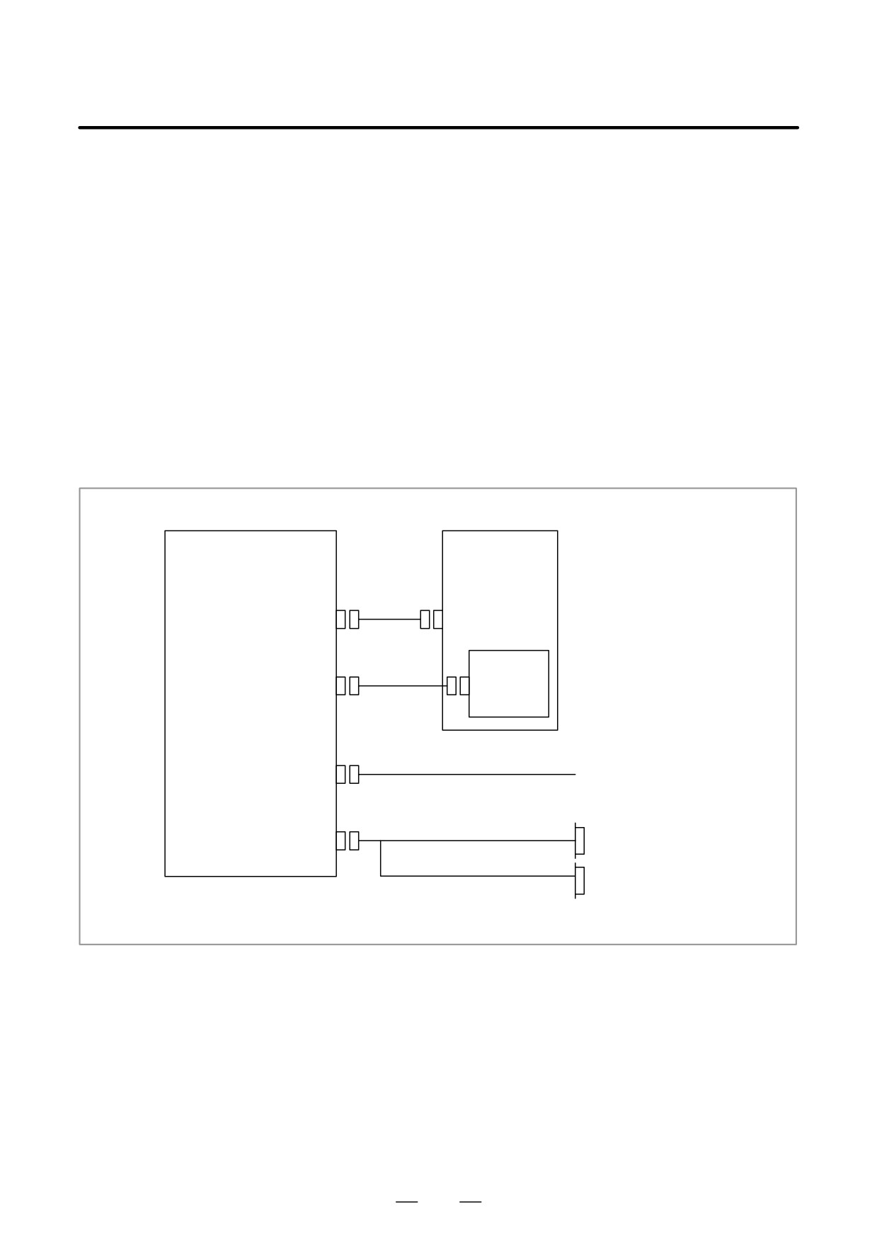
TOTAL CONNECTION
DIAGRAMS
For the 160is/180is/210is, the following connection is required, in addition to the connection common to the
16i/18i/21i/160is/180is/210is.
MDI unit
dedicated to PCs
MDI(CA55)
CK1
Backup(CA75)
Bakup unit
PC side ethernet(CD38S)
Hub, etc.
PC side RS-232-C(JD48)
RS-232-C I/O device
USB
USB
keyboard
printer
See Section 2.3, ”TOTAL CONNECTION DIAGRAMS” for connection other than the above.
246
B-63525EN/02
3. LCD-MOUNTED TYPE is SERIES HARDWARE
3.4
FS160is/180is/210is
MOTHERBOARD
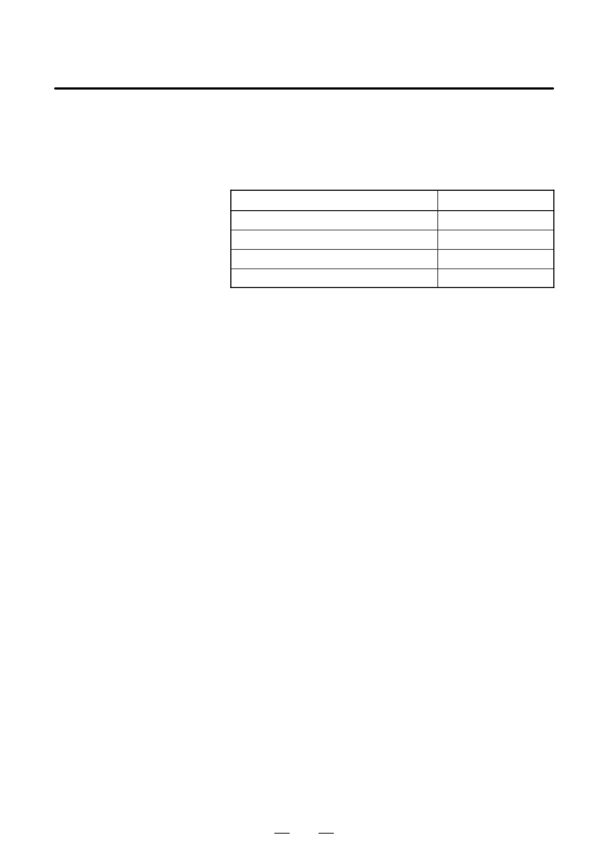
D Specifications
Item
Code
Series 160is motherboard
A20B-8100-0790
Series 180is motherboard
A20B-8100-0791
Series 210is motherboard (PMC-SA1)
A20B-8100-0794
Series 210is motherboard (PMC-SB7)
A20B-8100-0795
247
3. LCD-MOUNTED TYPE is SERIES HARDWARE
B-63525EN/02
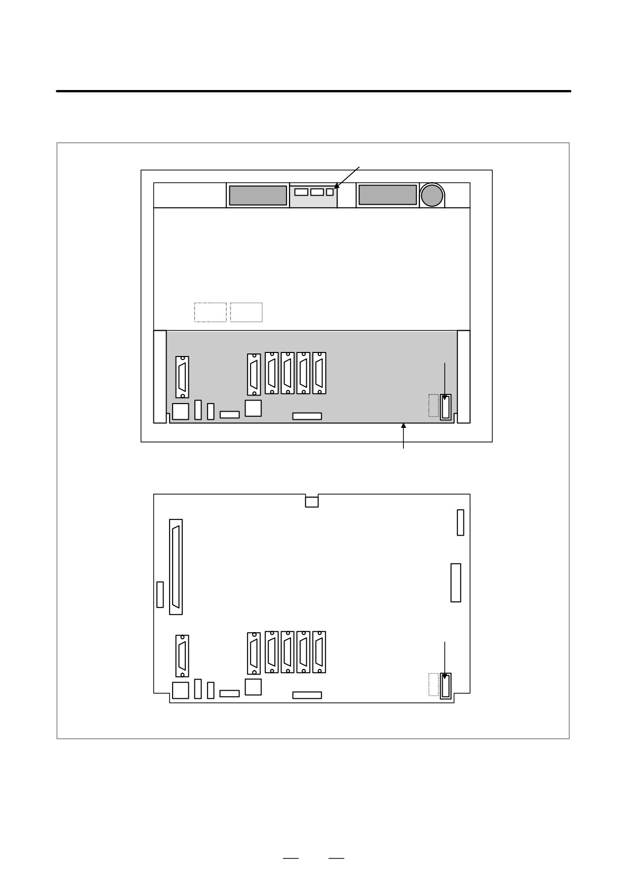
D Mounting positions of
connectors
Connector unit
Fan motor
Fan motor
Battery
Rear of unit
COP10A-1
COP10A-2
(COP10A is a connector installed on the servo card.)
JD36A
JA40
JA41
JD36B
JD44A
CP1
CA69
CN2
CD38S
CA55
CD38A
CA75
Motherboard
CN8
CN3
JNA
PCMCIA2
Motherboard
TP1
JD36A JA40
JA41
JD36B JD44A
JD48
CP1
CA69
CN2
CA75
CD38S CA55
CD38A
248
B-63525EN/02
3. LCD-MOUNTED TYPE is SERIES HARDWARE
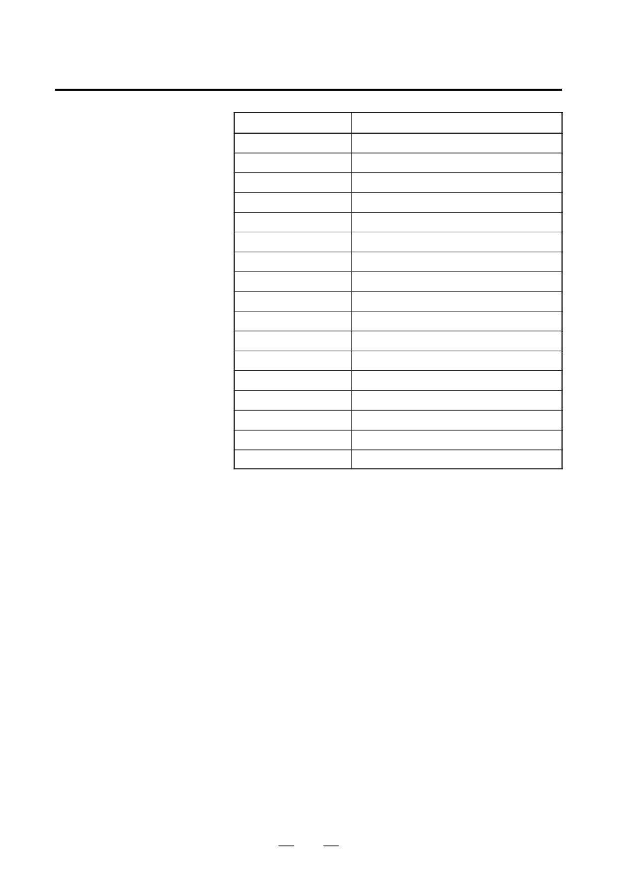
Connector number
Use
JD48
PC side RS232C, USB
COP10A-1, COP10A-2
Servo motor (FSSB)
CA55
MDI
CA69
Servo check
JD36A
RS232C serial port
JD36B
RS232C serial port
JA40
Analog output/High-speed DI
JD44A
I/O Link
JA41
Serial spindle/Position coder
CP1
DC24V-IN
CD38A
Ethernet(10BASE-T/100BASE-TX)
CD38S
PC side Ethernet(10BASE-T/100BASE-TX)
TP1
Touch panel
CA75
Backup unit
JNA
F-BUS interface
CN8
Video signal interface
PCMCIA2
PCMCIA interface
249
3. LCD-MOUNTED TYPE is SERIES HARDWARE
B-63525EN/02
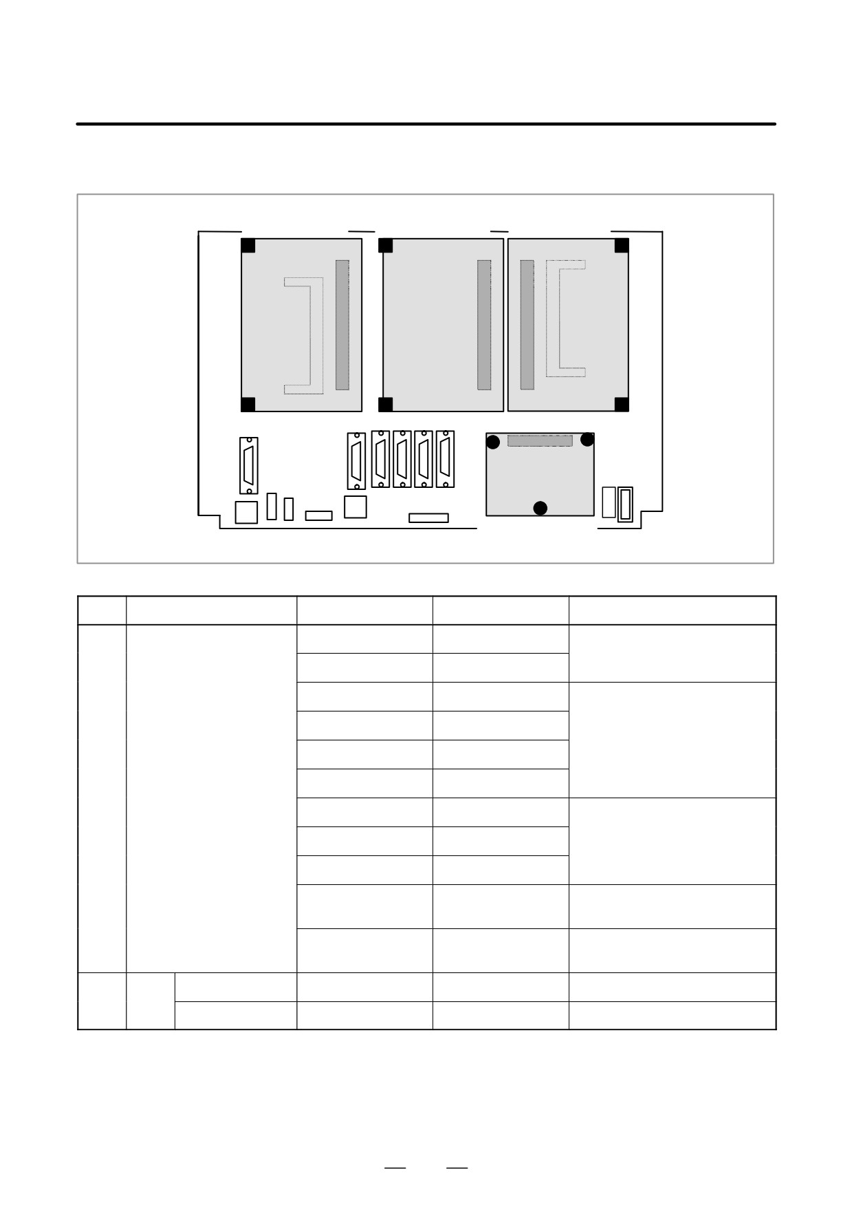
D Mounting positions of
cards
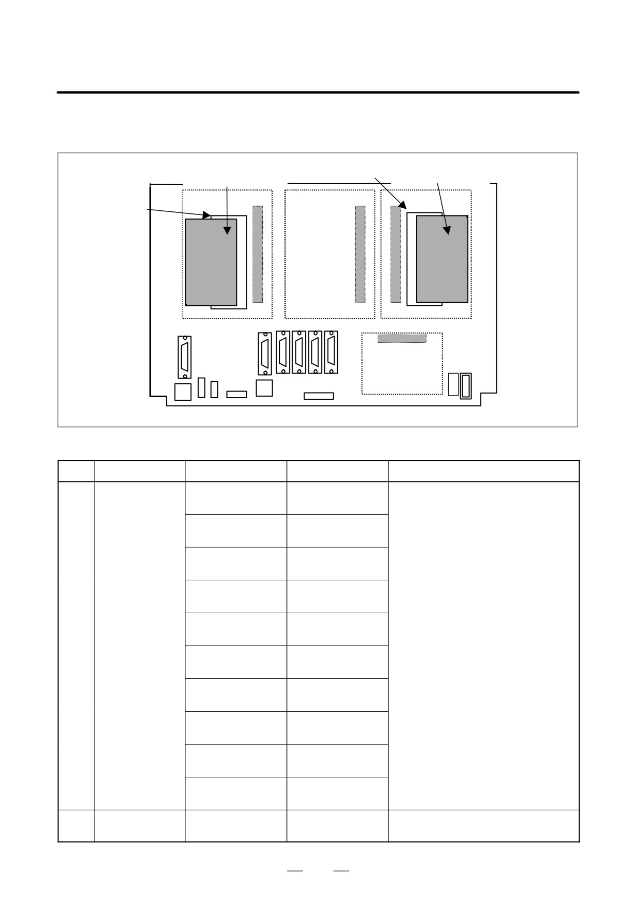
(1)
(2)
(3)
Axis control card
CE card
CPU card
Connector
Connector
Connector
DIMM module
DIMM module
Connector
(4)
Power supply unit
No.
Name
Code
Function
Remarks
(1)
Axis control card
A20B-3300-0033
Axis control 2-axes
Servo software Series 9090
A20B-3300-0032
Axis control 4-axes
A20B-3300-0243
Axis control 2-axes
Servo software Series 90B0
A20B-3300-0242
Axis control 4-axes
A20B-3300-0241
Axis control 6-axes
A20B-3300-0240
Axis control 8-axes
A20B-3300-0248
Axis control 4-axes
Servo software Series 90B0
(High-speed HRV)
A20B-3300-0245
Axis control 6-axes
A20B-3300-0244
Axis control 8-axes
A20B-3300-0246
Learning controlled
Servo software Series 90B3/90B7
axis control
A20B-3300-0247
Learning controlled
Servo software Series
axis control
90B3/90B7(High-speed HRV)
(2)
CE
CE card 1
A20B-3300-0330
For 10.4” color LCD
card
CE card 2
A20B-3300-0320
Win CE CPU
250
B-63525EN/02
3. LCD-MOUNTED TYPE is SERIES HARDWARE
No.
Name
Code
Function
Remarks
(3)
CPU card
A20B-3300-0310
For Series 160is/
180is
DRAM 16MB
A20B-3300-0311
For Series 160is/
180is
DRAM 32MB
A20B-3300-0291
For Series 210is
DRAM 16MB
A20B-3300-0290
For Series 210is
DRAM 32MB
A20B-3300-0312
For Series 210is
When the series 210is uses the
DRAM 16MB
PC’s embedded Ethernet feature
A20B-3300-0313
For Series 210is
DRAM 32MB
(4)
Power supply unit
A20B-8100-0720
NOTE
See Section 3.5, ”CE CARD” for the configuration of the CE
card.
251
3. LCD-MOUNTED TYPE is SERIES HARDWARE
B-63525EN/02
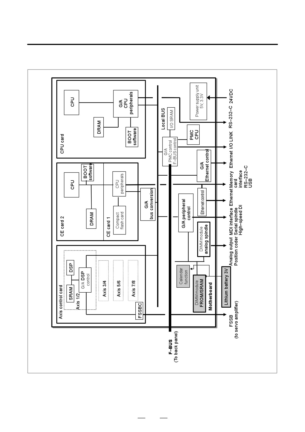
D Mounting positions of
DIMM module
(1) FROM/SRAM
DIMM module
(2) Analog spindle module
module
Connector
Connector
Connector
DIMM module
Connector
Motherboard
No.
Name
Code
Function
Remarks
(1)
FROM/SRAM
A20B-3900-0160
FROM 16MB
FROM contains various types of control
module
SRAM 1MB
software.
SRAM is battery-backed memory.
A20B-3900-0161
FROM 16MB
SRAM 2MB
A20B-3900-0162
FROM 16MB
SRAM 3MB
A20B-3900-0163
FROM 32MB
SRAM 1MB
A20B-3900-0164
FROM 32MB
SRAM 2MB
A20B-3900-0165
FROM 32MB
SRAM 3MB
A20B-3900-0180
FROM 16MB
SRAM 256kB
A20B-3900-0181
FROM 16MB
SRAM 512kB
A20B-3900-0182
FROM 32MB
SRAM 256kB
A20B-3900-0183
FROM 32MB
SRAM 512kB
(2)
Analog spindle
A20B-3900-0170
Analog spindle posi-
module
tion coder
252
B-63525EN/02
3. LCD-MOUNTED TYPE is SERIES HARDWARE
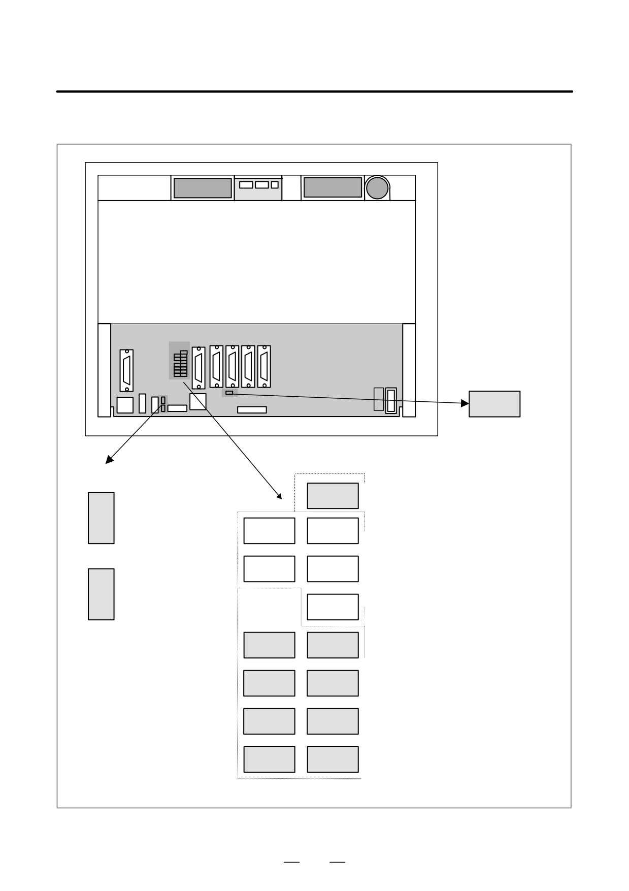
D Block diagram
253
3. LCD-MOUNTED TYPE is SERIES HARDWARE
B-63525EN/02
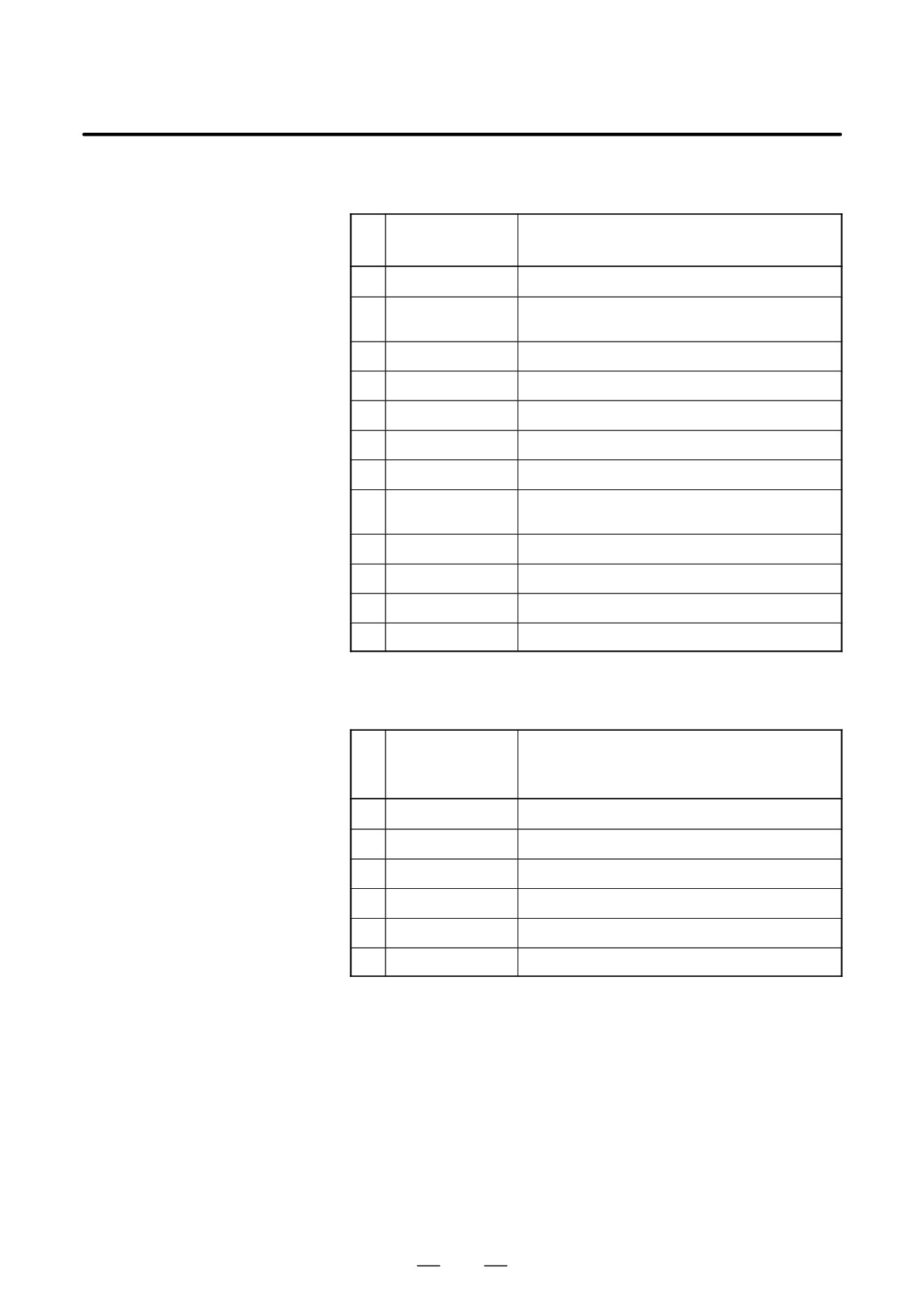
D LED display
Rear of unit
LED
LINK
Indicates the link state of the
Ethernet on the NC side.
This LED lights when a link
is established.
PC
Status (Green)
D2
Flashes while data is being
POWER
sent or received over the
Ethernet on the PC side.
SYSFAIL
PARITY1
PARITY2
SVALM
Alarm (Red)
D3
Lights when a link is
established in 100 Mb/s
mode over the Ethernet
on the PC side.
SYSEMG
LED8
LED4
LED7
LED3
Status (Green)
* LED1 to LED4 : NC side status
LED6
LED2
LED5 to LED8 : PC side status
LED5
LED1
See next page.
254
B-63525EN/02
3. LCD-MOUNTED TYPE is SERIES HARDWARE
(1) Changes in status LED (green) indication at power-on time (NC side
status : Green LED)
No.
Status LED
Status
1.2.3.4
1
jjjj
Power is not supplied.
2
JJJJ
Initial status immediately after power is switched on; boot
is running.
3
jJJJ
System activation started.
4
JjJJ
Waiting for each processor ID in the system to be set up.
5
jjJJ
Each processor ID in the system has been set up.
6
JJjJ
FANUC bus initialized.
7
jJjJ
PMC initialized.
8
JjjJ
Information about the hardware configuration of each
printed-circuit board in the system has been set up.
9
jjjJ
PMC ladder initialized.
10
jJJj
Waiting for digital servo to be initialized.
11
JJJj
Digital servo initialized.
12
Jjjj
Initialization completed, and usual operation under way.
J: On j: Off
(2) Changes in status LED (green) indication at power-on time (PC side
status : Green LED)
No.
Status LED
Status
(LED 5 to 8)
5.6.7.8
1
jjjj
Power is not supplied.
2
JJJJ
Initial status immediately after power is switched on.
3
JJJj
The NC to PC interface is being initialized.
4
JJjJ
Waiting for the PC to boot.
5
JJjj
The NC screen is displayed on the PC.
6
Jjjj
Operating normally after starting up successfully.
J: On j: Off
255
3. LCD-MOUNTED TYPE is SERIES HARDWARE
B-63525EN/02
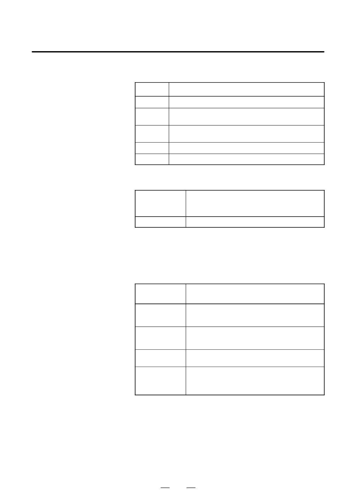
(3) Alarm LED (red) indication at system alarm occurrence
If any of these LEDs lights, it is likely that the hardware is defective.
Alarm LED
Meaning
SVALM
Servo alarm
SYSEMG
Lights when a system alarm occurs. The hardware has detected a fail-
ure in the system.
SYSFAIL
Lights when a system alarm occurs. Used by the software to stop the
system. Lights while boot is under way.
PARITY1
SRAM parity alarm
PARITY2
Common RAM parity alarm between NC and PC
(4) Status LED (red) indication at error occurrence (PC side status : Green
LED)
Status LED
Status
(LED 5 to 8)
5.6.7.8
jJjj
Common RAM parity alarm between NC and PC
J: On j: Off
(5) PC POWER (green LED) lights when the CE card is powered on
(including during backup operation).
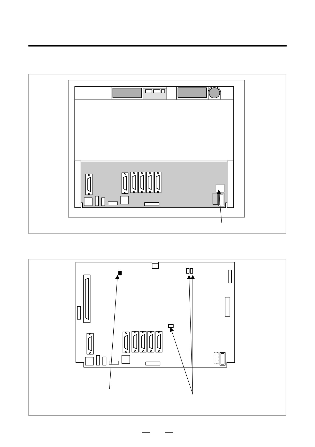
D Rotary switch setting
For the LCD-mounted type, the startup sequence used during power-up
can be changed by the rotary switch on the mother board.
Rotary switch
Contents
setting
0
Setting for maintenance.
The start menu is displayed. It is possible to start boot and IPL
from the PC.
1
Setting for usual operation.
The start menu is not displayed.
It is impossible to start boot or IPL from the PC.
2
Setting for maintenance.
Normally, this position is not used.
7
Setting for maintenance.
The start menu is displayed when MDI keys <6> and <7> are
pressed.
It is possible to start boot or IPL from the PC.
See Appendix, ”MAINTENANCE OF OPEN CNC (BOOT-UP AND
IPL),” for details on boot-up and IPL operations when the rotary switch
is set to 0.
256
B-63525EN/02
3. LCD-MOUNTED TYPE is SERIES HARDWARE
Mounting position of rotary switch (LCD-mounted type CNC)
Rear of unit
Rotary switch
D Short plug settings
Mother board
TMIL1 (short)
Be sure to insert these short plugs.
RESERVE (open)
Be sure to remove these short plugs.
(For some boards, the pins for these short plugs are not mounted.)
257
3. LCD-MOUNTED TYPE is SERIES HARDWARE
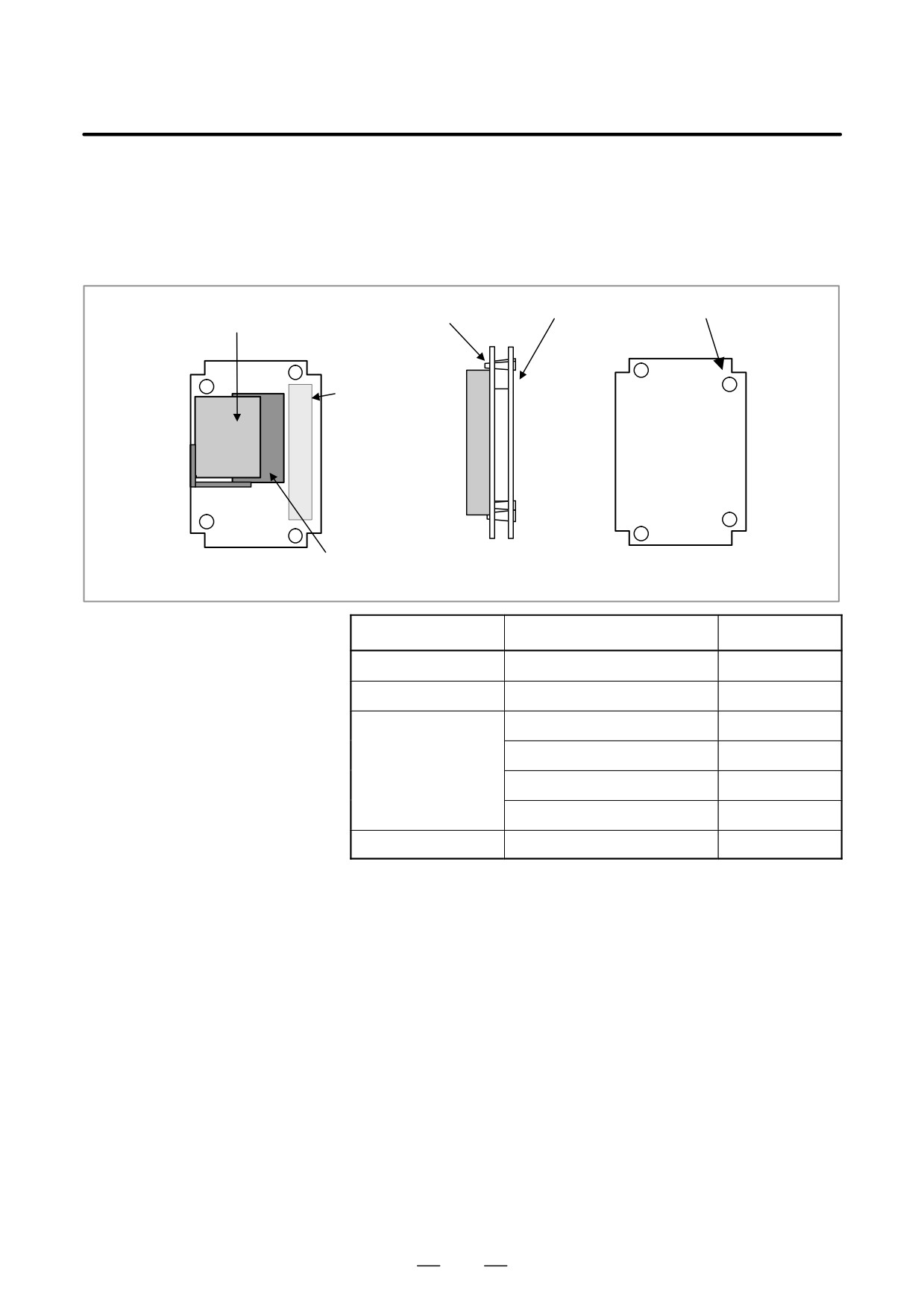
B-63525EN/02
The CE card has a different configuration from other card printed-circuit
3.5
boards.
CE CARD
CE cards 1 and 2 are combined and the compact flash card is attached.
D CE card configuration
CE card 2
Spacer
CE card 1
Compact flash card
Õ
Connector
Õ
Õ
Õ
Õ
Õ
Õ
CE card
Compact flash card
CE card
CE card
CE card 1 side
Side view
CE card 2 side
Item
Cord
Remarks
CE card 1
A20B-3300-0330
10.4” LCD
CE card 2
A20B-3300-0320
Compact flash card
A87L-0001-0173#032MBA
32MB
A87L-0001-0173#048MBA
48MB
A87L-0001-0173#064MB
64MB
A87L-0001-0173#096MB
96MB
Spacer
A98L-0005-0208
258
B-63525EN/02
3. LCD-MOUNTED TYPE is SERIES HARDWARE
3.6
INSTALLING AND
REMOVING
OPTIONAL BOARDS
3.6.1
Installing and
Removing the Mother
WARNING
Board
Only those personnel who were well trained for
maintenance and safety can perform the replacement.
When removing the board with the cabinet open, be careful
not to touch the part containing high-voltage circuits
(
indicated by the electric shock mark and covered with
the electric shock prevention sheet). If you touch the part
when the sheet comes off, you receive an electric shock.
CAUTION
Before starting replacement work, back up the contents
(such as parameters and programs) of the SRAM memory
of the CNC. Otherwise, the contents of the SRAM memory
may be lost during replacement work.
(1) Loosen the four screws that retain the case, then remove the case. At
this time, do not disconnect the cables for the fan and battery.
259
3. LCD-MOUNTED TYPE is SERIES HARDWARE
B-63525EN/02
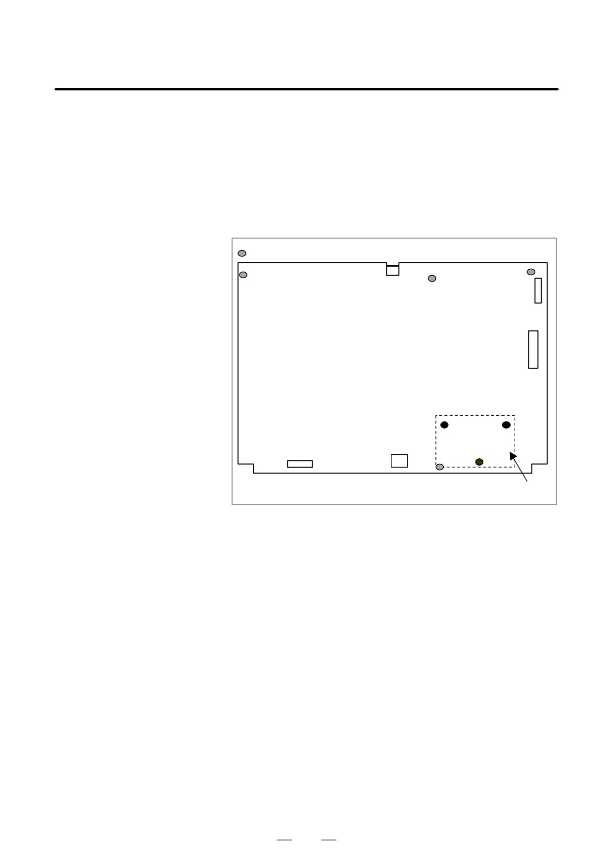
(2) Loosen the three screws that retain the power supply unit and remove
the unit. Then disconnect the cables from PCMCIA2 (PCMCIA
interface connector), CN8 (video signal interface connector), and CN2
(soft key connector) located on the mother board. When the touch
panel is attached, also disconnect TP1 (touch panel connector).
Remove the screws that retain the mother board. Since connector CN3
(inverter connection connector) directly engages the mother board and
the inverter printed circuit board, remove the mother board while
sliding it downward.
Location of screw hole
CN3
CN8
PCMCIA2
Mother board
CN2
Power supply unit
(3) To install the mother board, reverse steps (1) and (2).
260
B-63525EN/02
3. LCD-MOUNTED TYPE is SERIES HARDWARE
3.6.2
Installing and
Removing the CE Card
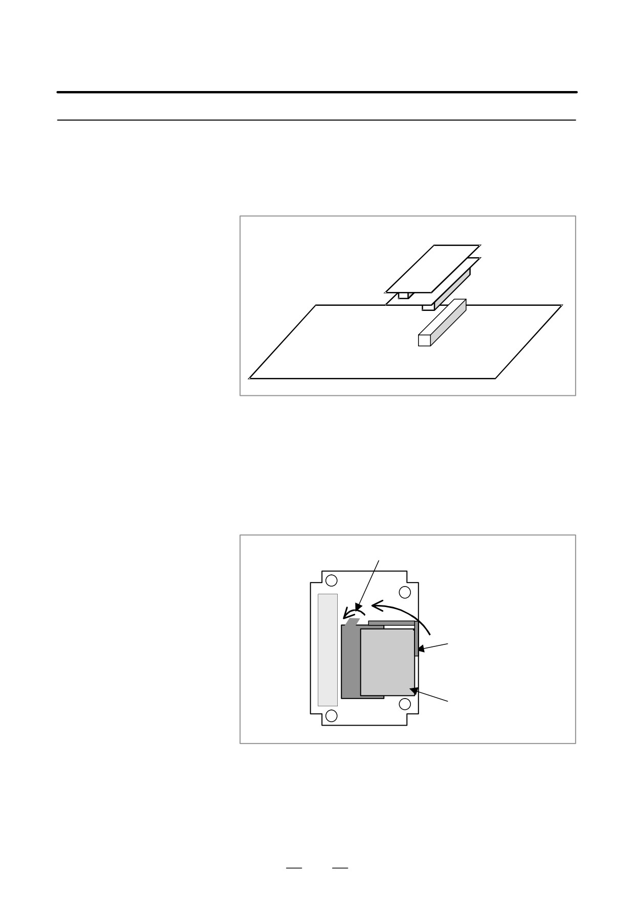
D Removing the CE card
CE card
Mother board
Remove the CE cards from the mother board. (Remove these cards from
the plug connector on the mother board with CE card 1 and CE card 2
engaged.)
D Removing the compact
S On side B (on which the plug connector for engaging the mother board
flash card
is mounted), CE card 1 and the compact flash card are installed. Since
the compact flash card is retained with a holding bracket, rotate the
bracket upward to unlock it. Remove the bracket and rotate the latch
to eject the compact flash card.
Latch
CE card 1
Rotate inward.
(Side B)
Holding bracket
Rotate upward.
Compact flash card
261
3. LCD-MOUNTED TYPE is SERIES HARDWARE
B-63525EN/02
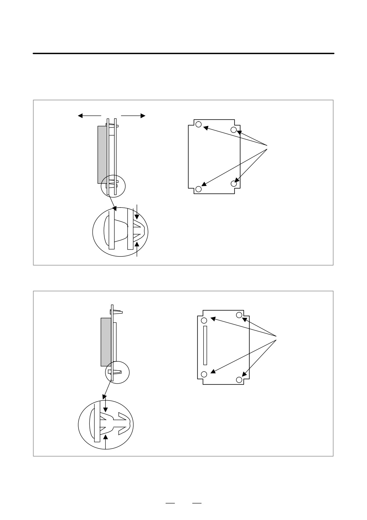
D Separating CE card 1
S On side A, CE card 2 is installed. Press both sides of the latch section
from CE card 2
of each spacer engaging CE cards 1 and 2 to unlock the latch, then
remove CE card 1.
CE card 2
(side A)
Õ
Õ
Spacer
Õ
Õ
Õ
Õ
Remove the
ÕÕ
card while press-
ing the both
CE card
sides of the latch
(CE card 2 side)
section.
D Removing spacers
Pull out a spacer while pressing the both sides of the latch section.
CE card 1
(side A)
Spacer
Pull out a spacer
while pressing the
both side of the
latch section.
262
B-63525EN/02
3. LCD-MOUNTED TYPE is SERIES HARDWARE
D Attaching the spacers
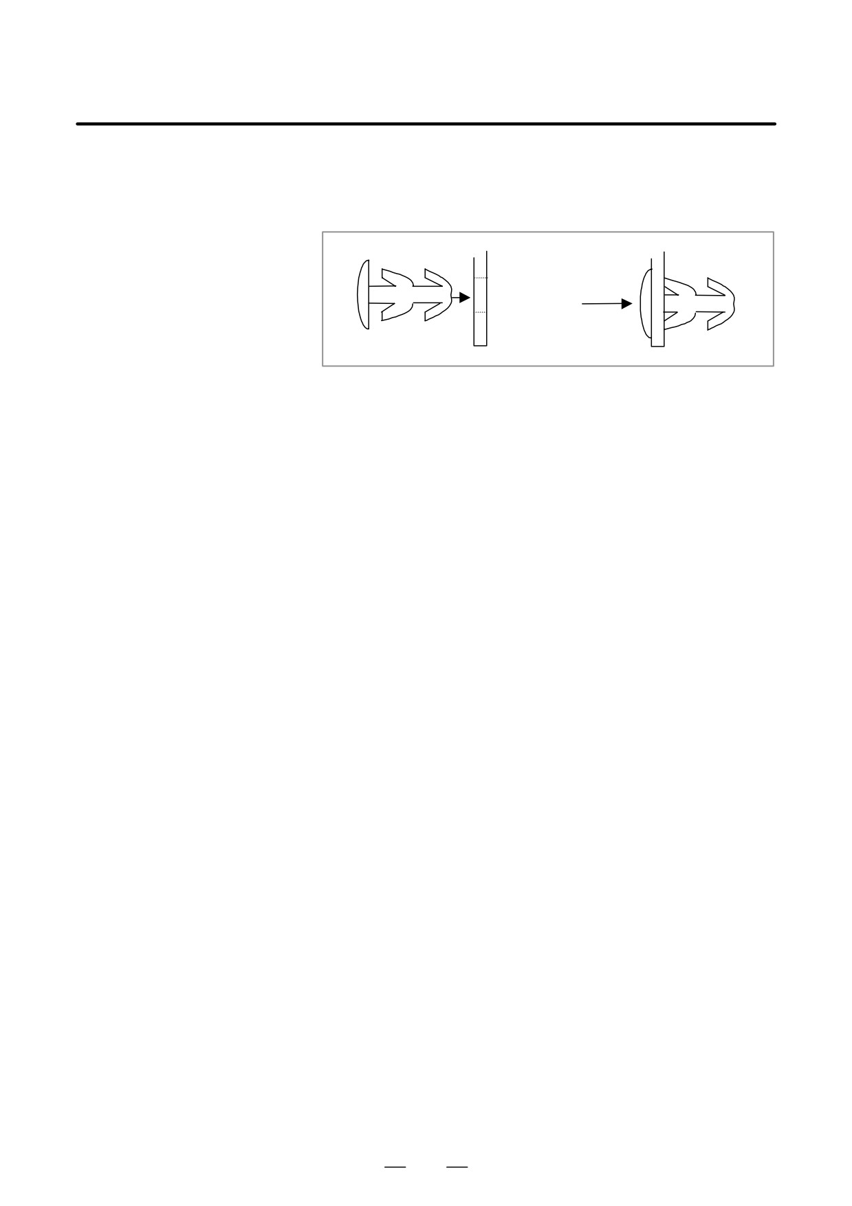
On side B (on which the connector for combining the mother board is
(spacer specification:
mounted), insert a spacer into a spacer hole.
A98L-0005-0208)
Press the spacer until the latch on side A is completely open.
D Installing other parts
To install other parts, reverse the procedure for removing them.
263
3. LCD-MOUNTED TYPE is SERIES HARDWARE
B-63525EN/02
Printed circuit boards
3.7
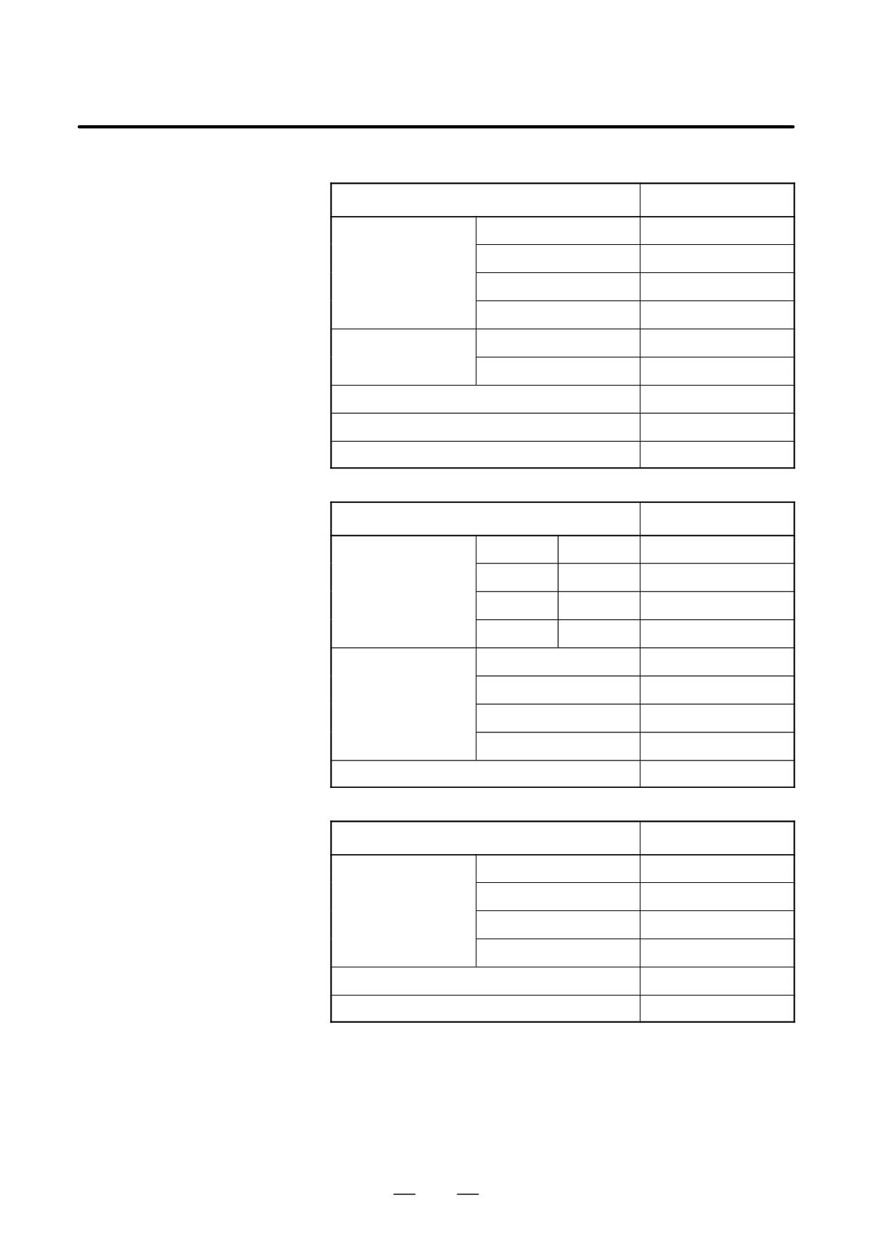
LIST OF UNITS AND
Name
Drawing number
PRINTED CIRCUIT
Motherboard
160is
A20B-8100-0790
BOARDS
180is
A20B-8100-0791
210is (SA1)
A20B-8100-0794
210is (SB7)
A20B-8100-0795
CE card
CE card 1
A20B-3300-0330
CE card 2
A20B-3300-0320
Power supply unit
A20B-8100-0720
Printed circuit board of Inverter
A20B-8001-0920
Printed circuit board of backup unit
A20B-2100-0820
Units
Name
Drawing number
LCD unit
Soft keys
Touch panel
(10.4” LCD)
Ę
A02B-0281-D505
Ę
A02B-0281-D506
Ę
Ę
A02B-0281-D507
Case Unit
No slot
A02B-0281-C600
2 slots
A02B-0281-C602
3 slots
A02B-0281-C603
4 slots
A02B-0281-C604
FA full-keyboard
A02B-0281-C130#E
Others
Name
Drawing number
Compact flash card
32MB
A87L-0001-0173#32MBA
48MB
A87L-0001-0173#48MBA
64MB
A87L-0001-0173#64MB
96MB
A87L-0001-0173#96MB
Cable for backup unit
A02B-0281-K801
Cable for FA full-keyboard
A02B-0281-K802
264
B-63525EN/02
3. LCD-MOUNTED TYPE is SERIES HARDWARE
3.8
REPLACING THE
WARNING
FUSE ON THE UNITS
Before replacing the fuse, eliminate the cause by which the
fuse blew.
Therefore, only those personnel who were well trained for
maintenance and safety can perform the replacement.
When replacing the fuse with the cabinet open, be careful
not to touch the part containing high-voltage circuits
(
indicated by the electric shock mark and covered with
the electric shock prevention sheet). If you touch the part
when the sheet comes off, you receive an electric shock.
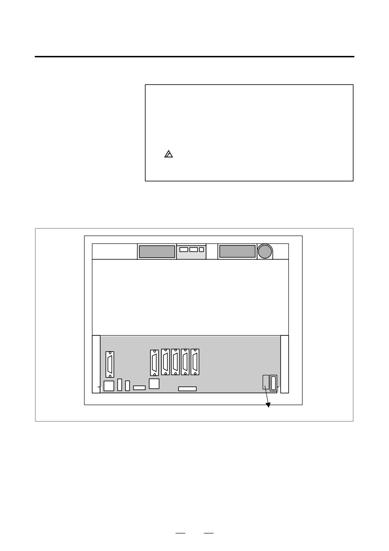
D Ordering number of fuse
A02B-0236-K101
D Location of Fuse
Rear of units
Fuse
265
3. LCD-MOUNTED TYPE is SERIES HARDWARE
B-63525EN/02
See Section 2.8, ”REPLACING THE BATTERY” for replacing the
3.9
battery.
REPLACING THE
BATTERY
3.10
REPLACING THE
FAN MOTOR
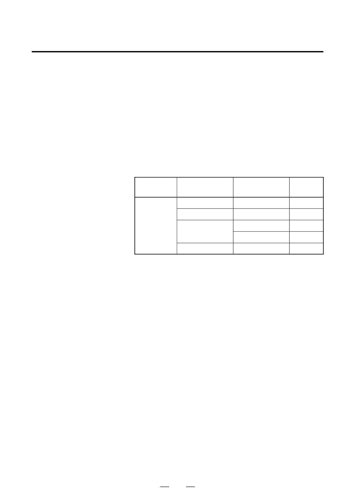
D Ordering number of fan
motor
Unit
Number of
Ordering number
Required
extension slot
number
LCD-mounted
No extension slot
A02B-0236-K120
2
type CNC
Extension slot 2
A02B-0236-K121
2
Extension slot 3
A02B-0236-K121
2
A02B-0236-K122
2
Extension slot 4
A02B-0236-K121
4
D Replacing method
See Section 2.9, ”REPLACING A FAN UNIT” for replacing the fan
motor.
266
B-63525EN/02
3. LCD-MOUNTED TYPE is SERIES HARDWARE
LCD back-light can not be replaced for LCD-mounted type is series
3.11
CNC.
REPLACING THE
LCD BACK-LIGHT
For the LCD display unit with a touch panel, the surface of the touch panel
3.12
is covered with the protection sheet to protect it. When there are flaws and
REPLACING THE
contamination on this protection sheet that make the screen hard to read,
TOUCH PANEL
replace the protection sheet. Prepare the following items.
PROTECTION SHEET
Item
Ordering number
Touch panel
10.4” LCD (with touch panel and soft keys)
A02B-0236-K110
protection sheet
10.4” LCD (with touch panel)
A02B-0236-K130
D Replacing method
See Section 5.4.
267
3. LCD-MOUNTED TYPE is SERIES HARDWARE
B-63525EN/02
3.13
BACKUP UNIT
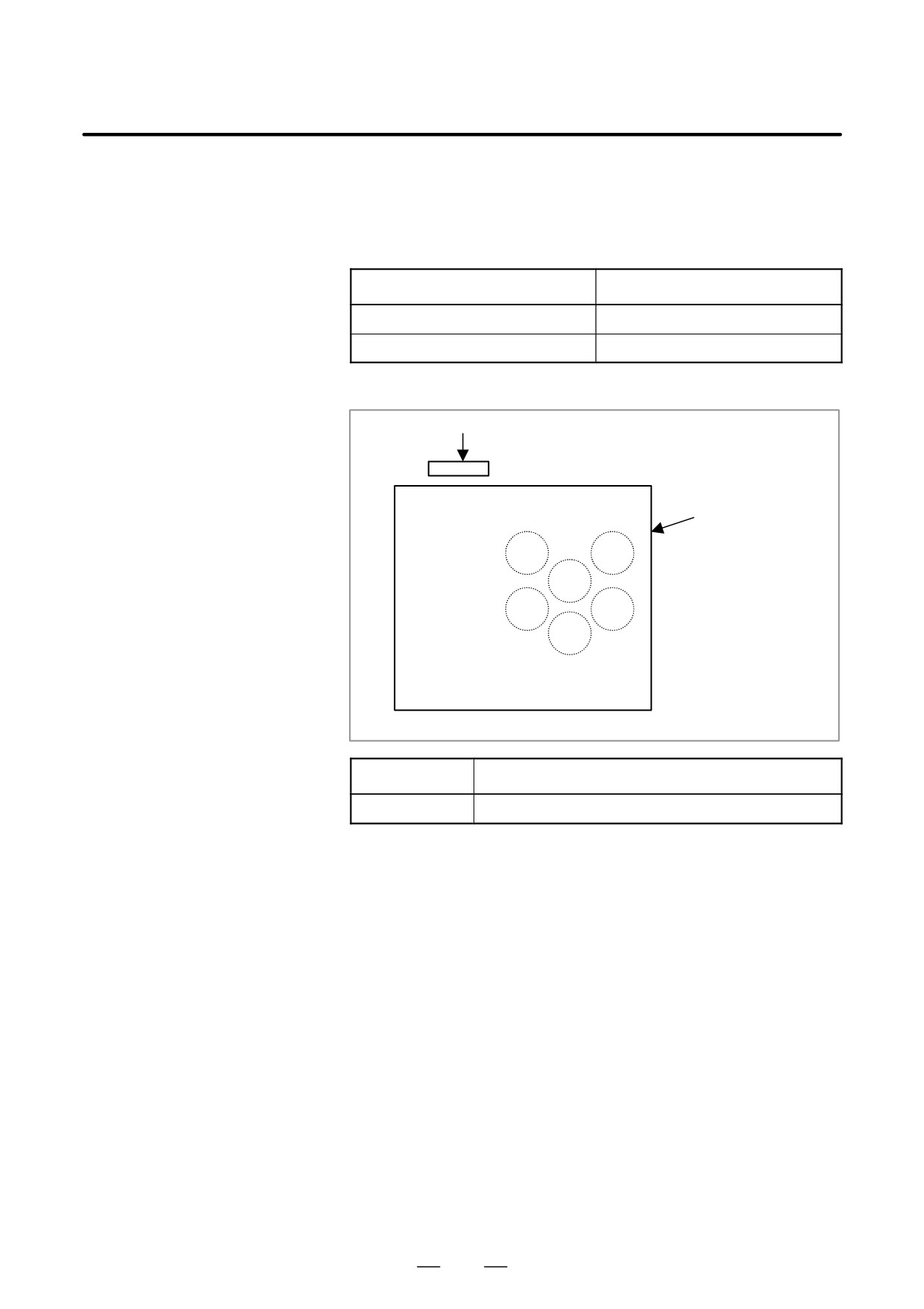
D Specifications
Item
Ordering number
Backup unit PCB
A20B-2100-0820
Backup unit cable
A02B-0281-K801
D Mounting positions of
connectors
CN9
Backup unit PCB
Front view
Connector name
Function
CN9
Supplying the backup power (main printed circuit board interface)
When the LED (PC POWER) on the main printed circuit board lights, do
not touch any parts in the basic unit and backup unit. The
FS160is/FS180is/FS210is operates for about 12 seconds after the main
power is turned off.
268
4. STAND-ALONE TYPE i SERIES HARDWARE
B-63525EN/02
STAND-ALONE TYPE i SERIES HARDWARE
4
This chapter describes the printed circuit boards of the CNC control unit
of the stand-alone type i series and card PCB functions on the printed
circuit boards. The chapter also describes procedures for replacing
consumable items.
4.1
HARDWARE CONFIGURATION
270
4.2
HARDWARE OVERVIEW
271
4.3
TOTAL CONNECTION DIAGRAMS
275
4.4
CONNECTOR AND CARD
CONFIGURATIONS OF PRINTED
CIRCUIT BOARDS
280
4.5
UNITS AND PRINTED CIRCUIT BOARDS
324
4.6
MOUNTING AND REMOVING
AN OPTION BOARD
335
4.7
MOUNTING AND REMOVING
THE BACK PANEL
340
4.8
REPLACING THE FUSE OF THE
CONTROL UNIT
342
4.9
REPLACING THE BATTERY
343
4.10 REPLACING A FAN UNIT
347
4.11 REPLACING THE FUSE OF THE LCD UNIT
348
4.12 REPLACING THE LCD BACKLIGHT
349
4.13 HEAT GENERATION OF THE UNITS
351
269
4. STAND-ALONE TYPE i SERIES HARDWARE
B-63525EN/02
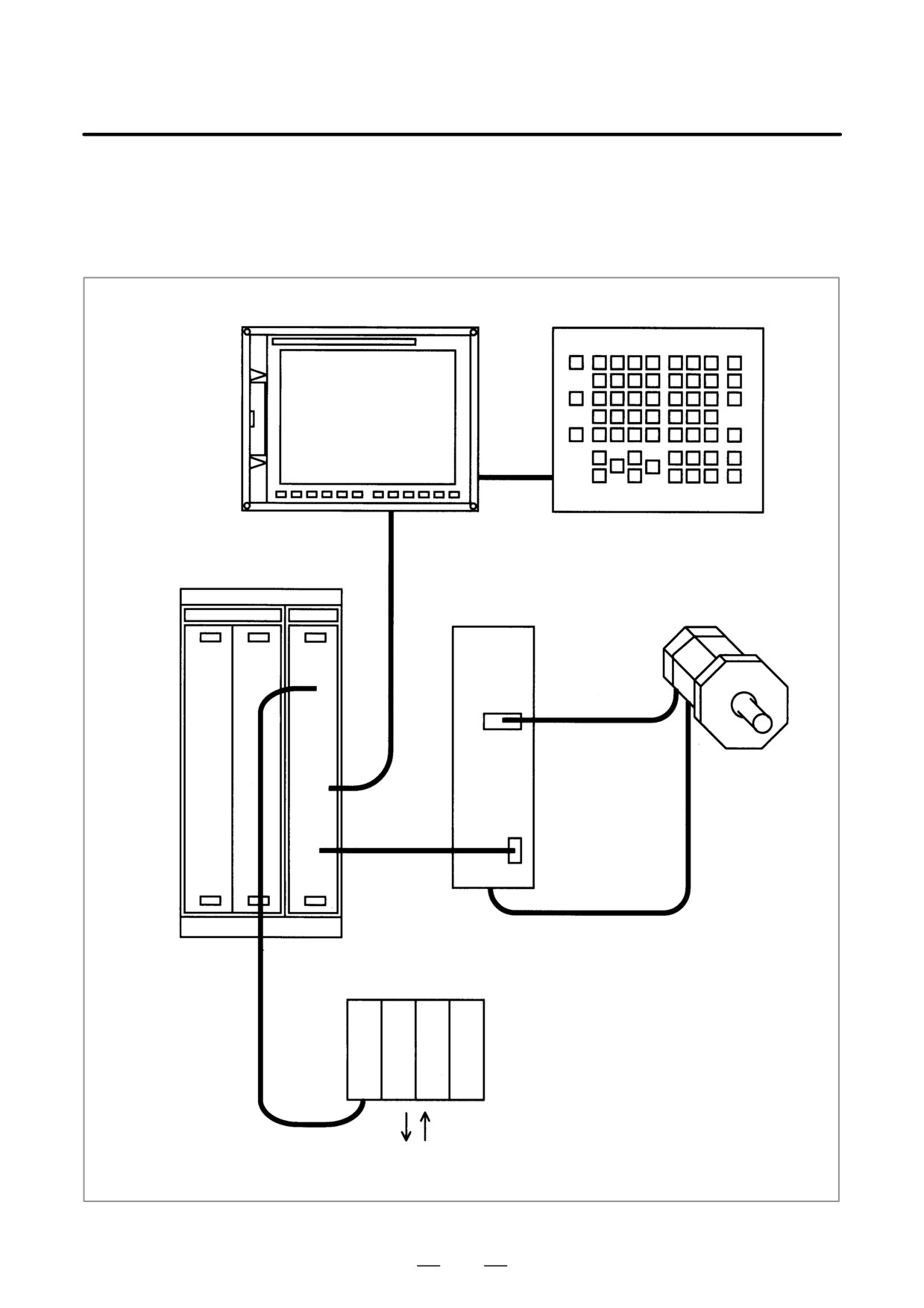
4.1
HARDWARE
CONFIGURATION
LCD unit
MDI unit
Control unit
Servo amplifier module/
Servo motor/
spindle amplifier module
spindle motor
Distributed I/O module, I/O unit MODEL-A, etc.
I/O Link
Machine operator’s panel, power
magnetic circuit, etc.
270
4. STAND-ALONE TYPE i SERIES HARDWARE
B-63525EN/02
4.2
HARDWARE
OVERVIEW
4.2.1
Series 16i/160i/160is
271