FANUC Series 16i/160i/160is-MODEL B, Series 18i/180i/180is-MODEL B, Series 21i/210i/210is-MODEL B. MAINTENANCE MANAUL - page 12
4. STAND-ALONE TYPE i SERIES HARDWARE
B-63525EN/02
4.4.5
C Board, Serial
Communication Board
D Specifications
Item
Code
C board
A20B-8100-0330
Serial communication board
R.B./DNC2: RS232C I/F
A20B-8100-0334
R.B./DNC2: RS422 I/F
A20B-8100-0335
DNC1: RS485 I/F
A20B-8100-0336
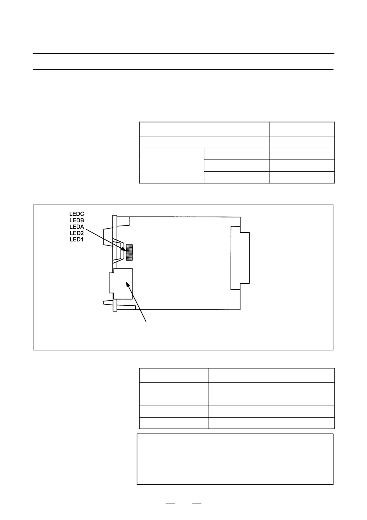
D Mounting positions of
connectors, LEDs, etc.
JNA
F-BUS backplane
connector
The connector is mounted on a serial communication board.
JD5L: RS232C interface
JD6L: RS422/485 interface
D LED display
D LED display when an error occurs
j: Off J: On
CBA
Status
jjJ
The CPU is not yet started (reset state).(*1)
JJj
A DRAM parity error occurred.
jJj
A bus error occurred in the CPU on this board.
Jjj
An error occurred in the local bus on this board.
NOTE
1
The LEDs display this pattern because the CPU is in the
reset state immediately after power-up.
2
If the LEDs display any of the patterns, the hardware may
be defective (except in the reset state at power-up).
302
4. STAND-ALONE TYPE i SERIES HARDWARE
B-63525EN/02
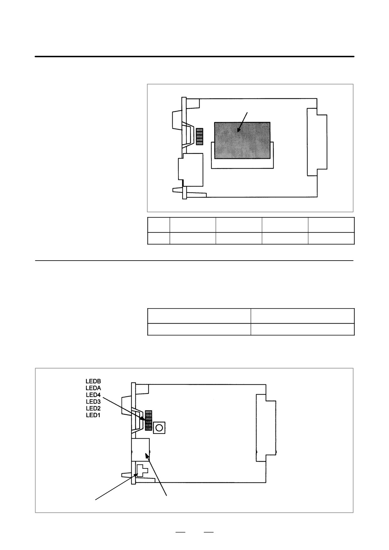
D Mounting positions of
card and DIMM module
(1) DRAM module
No.
Item
Code
Function
Remarks
(1)
DRAM module
A20B-3900-0042
System RAM
4MB
4.4.6
HSSB Interface Board
D Specifications
Item
Code
HSSB interface board
A20B-8001-0730
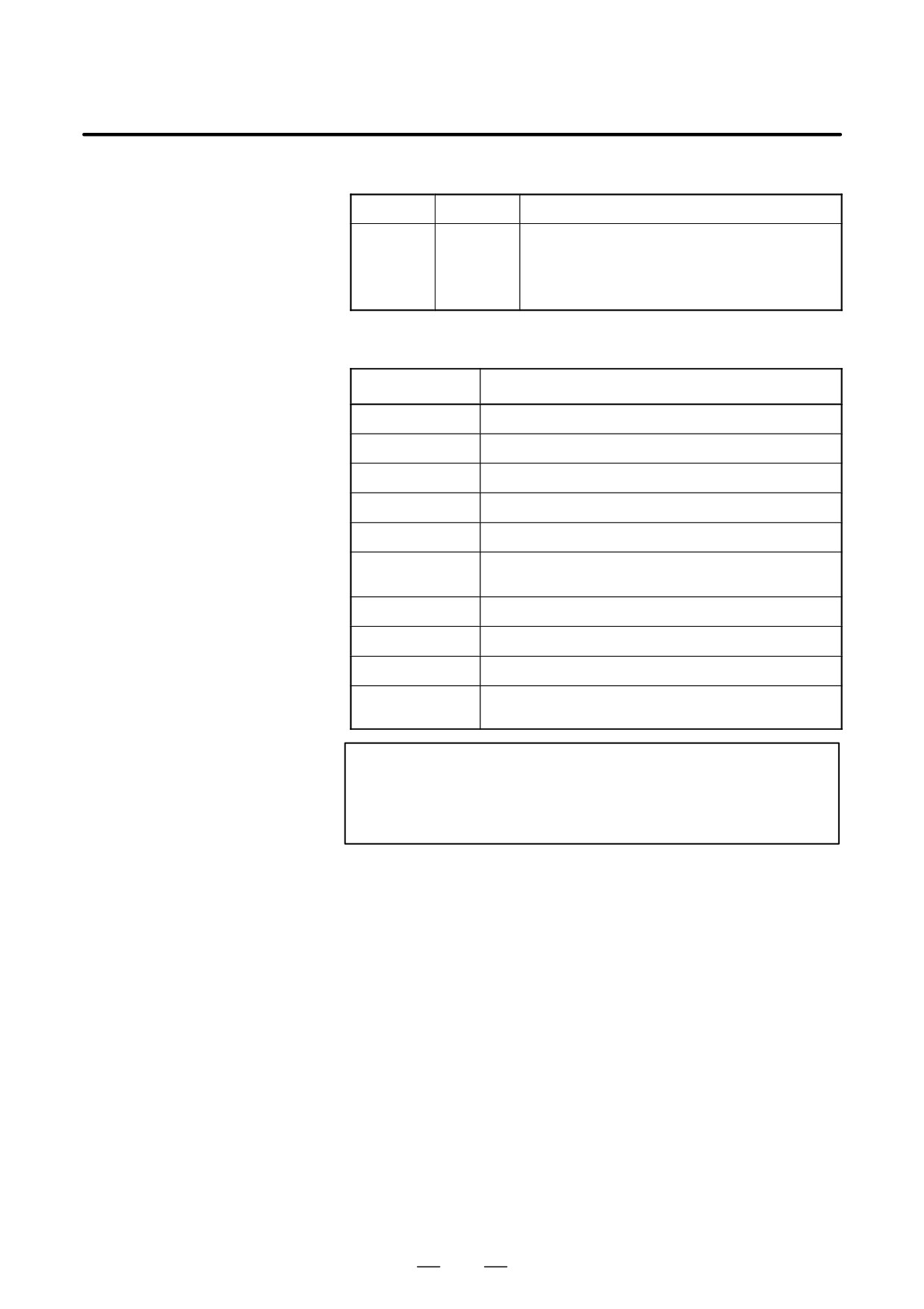
D Mounting positions of
connectors, LEDs, etc.
JNA
F-BUS backplane
SW1
connector
(Up to the PWB03 version)
SW1
(PWB04 version and later)
COP7: High-speed serial bus (HSSB) interface
303
4. STAND-ALONE TYPE i SERIES HARDWARE
B-63525EN/02
D LED display
LEDB
Red
HSSB communication has been interrupted.
LEDA
Red
A RAM parity alarm occurred in the common RAM on the
board.
The common RAM is mounted on this board. The RAM
is used to exchange information between the CNC and
personal computer and is not battery-backed.
Status display of the green LEDs
j: Off J: On
4 3 2 1
Status
JJJJ
Immediately after power-up
JJJj
HSSB board initialization in progress
JJjJ
Waiting for the booting of the PC side
JJjj
CNC screen displayed on the PC
Jjjj
Activation normally terminated, normal operation in progress
jJJj
Thermal error detected by the CNC display unit with PC
functions or PANEL i
jJjJ
HSSB communication interrupted
jJjj
Parity alarm in the common RAM
jjJJ
Communication error
jjJj
Battery alarm in the CNC display unit with PC functions or
PANEL i
NOTE
The PC used in the above table includes PANEL i, CNC
display unit with PC functions, and CNC display unit for the
is series CNC.
304
4. STAND-ALONE TYPE i SERIES HARDWARE
B-63525EN/02
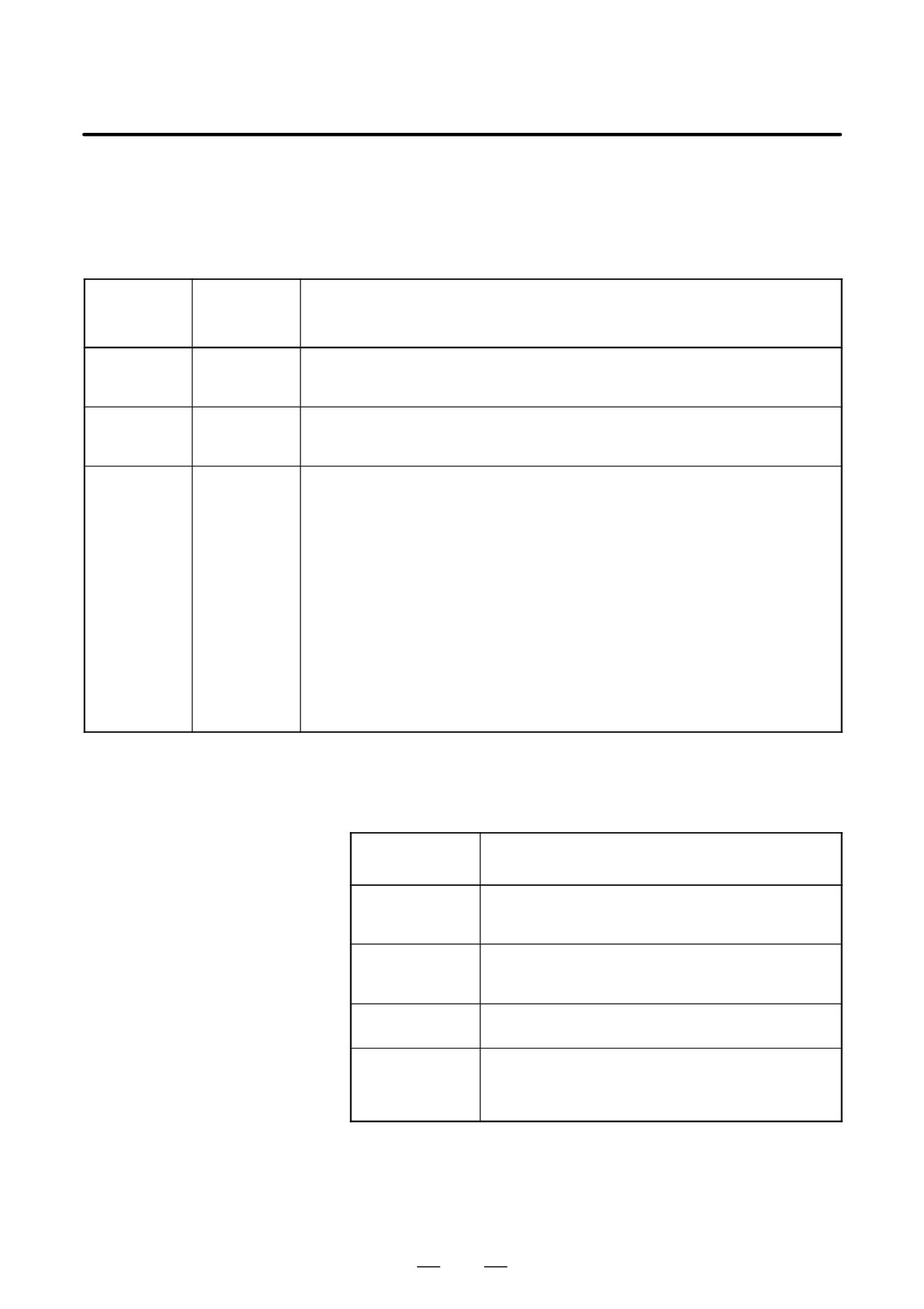
D Rotary switch
1) Setting of ROTARY SWITCH in case of connecting to PC or PANEL
i
The power-on start sequence can be modified using rotary switch on
the board.
setting of rotary
Description
switch
0
Setting for maintenance.
The start menu is displayed. It is possible to start boot and IPL
from the PC or PANEL i.
1
Setting for usual operation.
The start menu is not displayed.
It is impossible to start boot or IPL from the PC or PANEL i.
2
The CNC and PC or PANEL i are started independently of each
other without handshake.
* CNC
CNC is available if PC is not turned on or not connected.
(Display for CNC and MDI or Operation panel etc. are needed
to operate.)
The start menu is not displayed if PC or PANEL i is connected
and turned on.
* PC or PANEL i
The start menu is not displayed and it is impossible to start
boot or IPL from the PC or PANEL i if CNC is connected and
turned on.
This setting makes PC or PANEL i or CNC be able to be turned
on/off the power individually if HSSB device driver for Windows
95/98, NT4.0 or 2000 is installed.
In case of Multi-connection (connecting some CNCs to one PC
or PANEL i), please set to this setting usually.
NOTE
PANEL i used here represents hardware that can operate
on a stand-alone basis (provide a stand-alone option).
305
4. STAND-ALONE TYPE i SERIES HARDWARE
B-63525EN/02
2) Setting of ROTARY SWITCH in case of connecting to CNC display
unit with PC functions
The power-on start sequence can be modified using rotary switch on
the board and short terminal (SW5) on CNC display unit with PC
functions.
setting of
short
Description
rotary switch
terminal
(SW5)
0
OPEN
Setting for maintenance.
The start menu is displayed. It is possible to start boot and IPL from CNC display unit with PC
functions or PANEL i.
1
OPEN
Setting for usual operation.
The start menu is not displayed.
It is impossible to start boot or IPL from CNC display unit with PC functions or PANEL i.
2
SHORT
The CNC and CNC display unit with PC functions or PANEL i are started independently of each
other without handshake.
* CNC
CNC is available if CNC display unit with PC functions or PANEL i is not turned on or not con-
nected. (Display for CNC and MDI or Operation panel etc. are needed to operate.)
The start menu is not displayed if CNC display unit with PC functions or PANEL i is connected
and turned on.
* CNC display unit with PC functions or PANEL i
CNC display unit with PC functions or PANEL i is available if CNC is not turned on or not con-
nected.
Temperature management function of CNC display unit with PC functions or PANEL i doesn’t
work. Please make sure that the temperature is proper for CNC display unit with PC functions
or PANEL i.
The start menu is not displayed and it is impossible to start boot or IPL from CNC display unit
with PC functions or PANEL i if CNC is connected and turned on.
This position must be used at maintenance only.
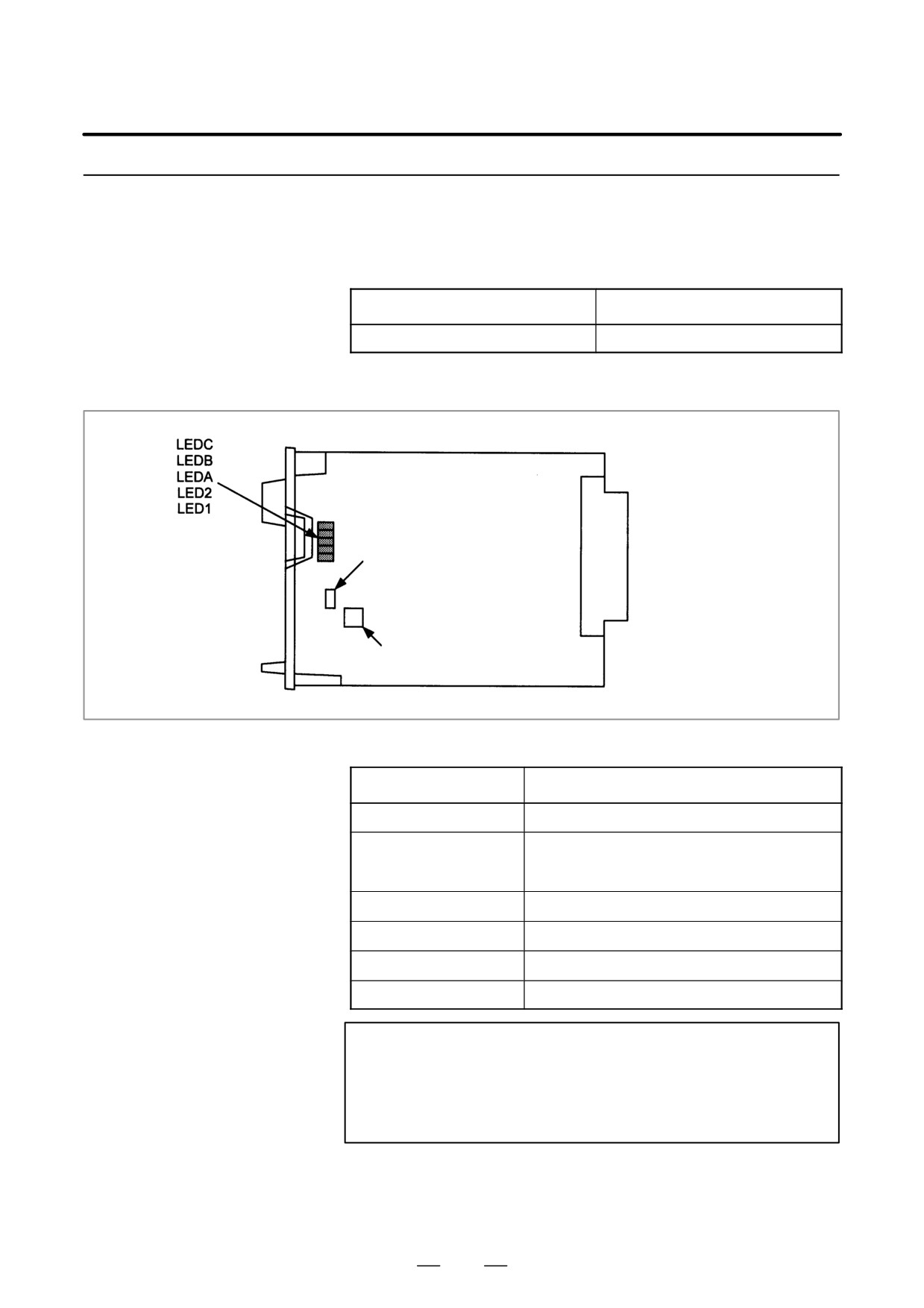
3) Setting of ROTARY SWITCH in case of connecting to CNC display
unit for is series CNC
The power-on start sequence can be modified using rotary switch on
the board. Normally, set this rotary switch to 1.
setting of rotary
Description
switch
0
Setting for maintenance.
The start menu is displayed. It is possible to start boot and IPL
from the PC.
1
Setting for usual operation.
The start menu is not displayed.
It is impossible to start boot or IPL from the PC.
2
Setting for maintenance.
Normally, this position is not used.
7
Setting for maintenance.
The start menu is displayed when MDI keys <6> and <7> are
pressed.
It is possible to start boot or IPL from the PC.
306
4. STAND-ALONE TYPE i SERIES HARDWARE
B-63525EN/02
4.4.7
Symbol CAPi T Board
D Specifications
Item
Code
Symbol CAPi T board
A20B-8100-0560
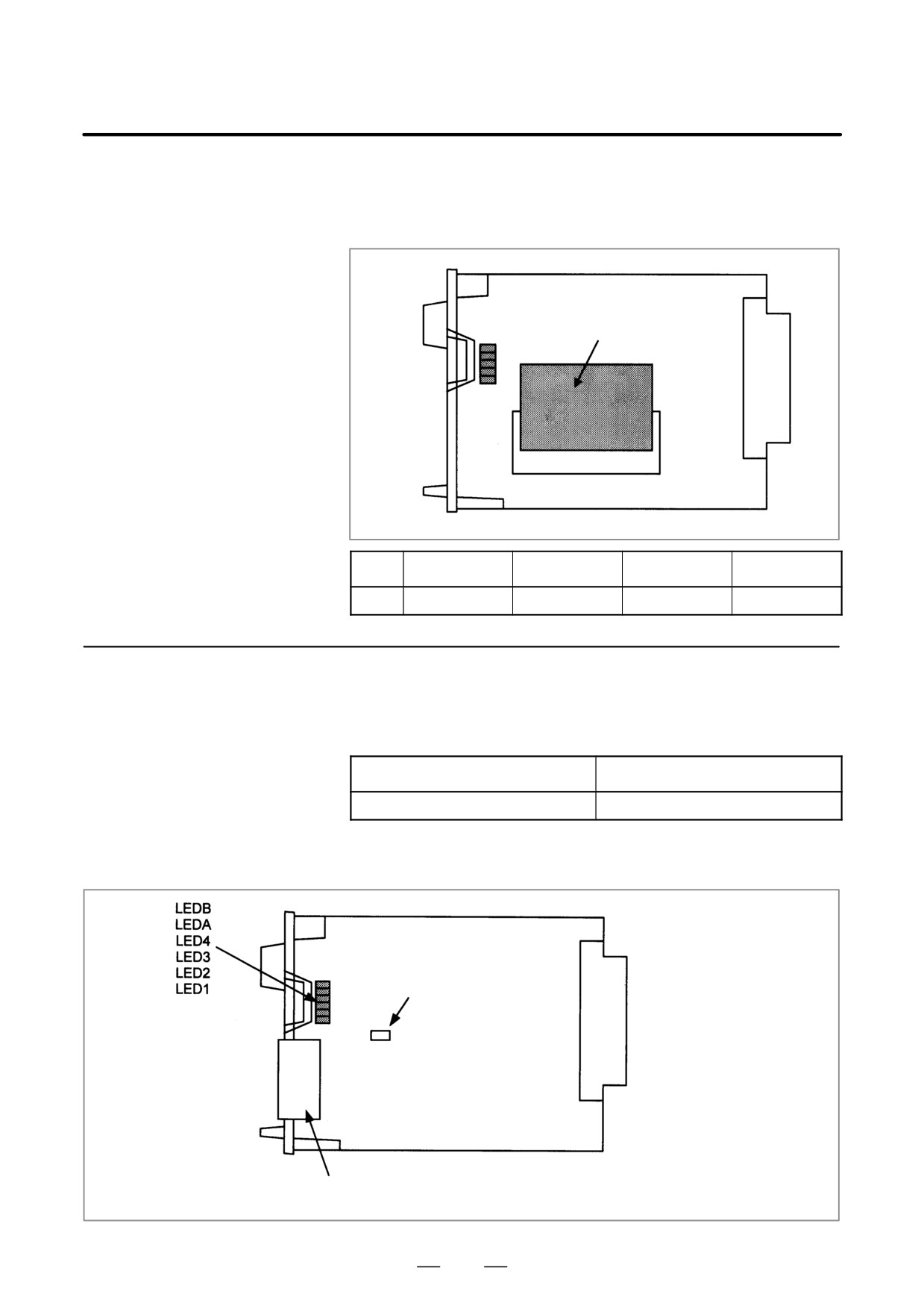
D Mounting positions of
connectors, LEDs, etc.
JNA
F-BUS backplane
connector
Setting pin TM1
Connector CP8B
D LED display
Status display of the red LEDs
j: Off J: On
CAB
Status
jjJ
An error occurred in the local bus on this board.
jJj
An error occurred in the local bus on this board. Alter-
natively, an error occurred on the main CPU board or
another option board.
jJJ
The CPU is not yet started (reset state).(*1)
Jjj
A parity alarm occurred in the SRAM.
JjJ
A bus error occurred in the CPU on this board.
JJj
A parity alarm occurred in the DRAM.
NOTE
1
The LEDs display this pattern because the CPU is in the
reset state immediately after power-up.
2
If the LEDs display any of the patterns, the hardware may
be defective (except in the reset state at power-up).
307
4. STAND-ALONE TYPE i SERIES HARDWARE
B-63525EN/02
D Setting pin TM1 and
Setting pin TM1 and connector CP8B are provided for testing at FANUC.
connector CP8B
The setting of the pin must not be changed.
D Mounting positions of
card and DIMM module
(1) DRAM module
No.
Item
Code
Function
Remarks
(1)
DRAM module
A20B-3900-0042
System RAM
4MB
4.4.8
I/O Link-II Board
D Specifications
Item
Code
I/O Link-II board
A20B-8100-0381
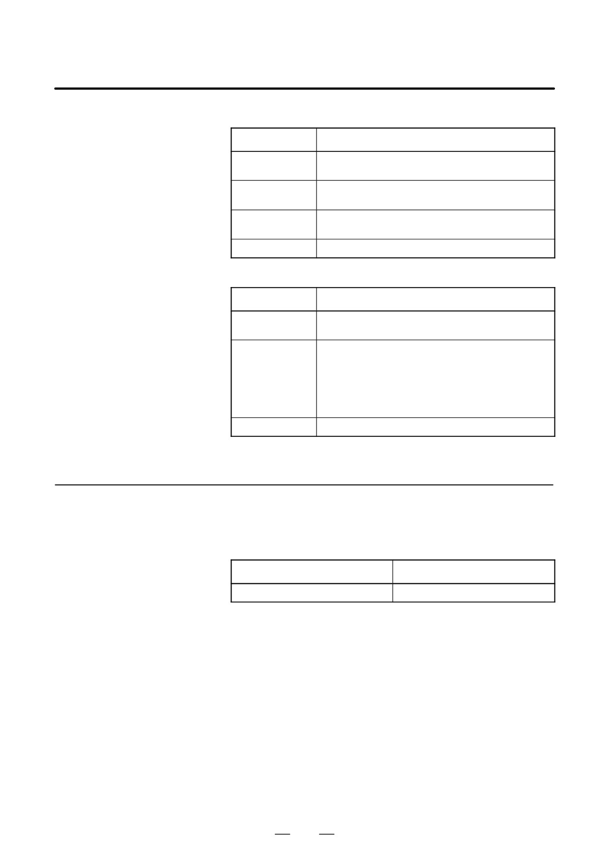
D Mounting positions of
connectors, LEDs, etc.
JNA
Setting pin SH1
F-BUS backplane
connector
TBA: I/O Link-II interface
308
4. STAND-ALONE TYPE i SERIES HARDWARE
B-63525EN/02
D LED display
D Status LED display (green)
Status
LED1
Lit when the board is released from the reset state and starts
operating.
LED2
Lit when communication starts. This LED is left on until a reset
occurs.
LED3
Lit each time transmission is performed. (Actually, this LED
appears to be lit continuously.)
LED4
Reserved
D Alarm LED display (red)
Status
LED1
Lit when the board is released from the reset state and starts
operating.
LEDA
Lit if any of the following errors is detected when data is re-
ceived. This LED goes off when normal data is received next.
· Reception buffer overflow
· Fractional bit data detection
· Overrun error detection
· CRC error detection
· Abort error detection
LEDB
Lit when a parity alarm occurs in the DRAM on this board.
D Setting pin SH1
This pin is used to set the I/O Link-II board as the master or slave.
4.4.9
Ethernet Board
D Specifications
Item
Code
Ethernet board
A20B-8100-0450
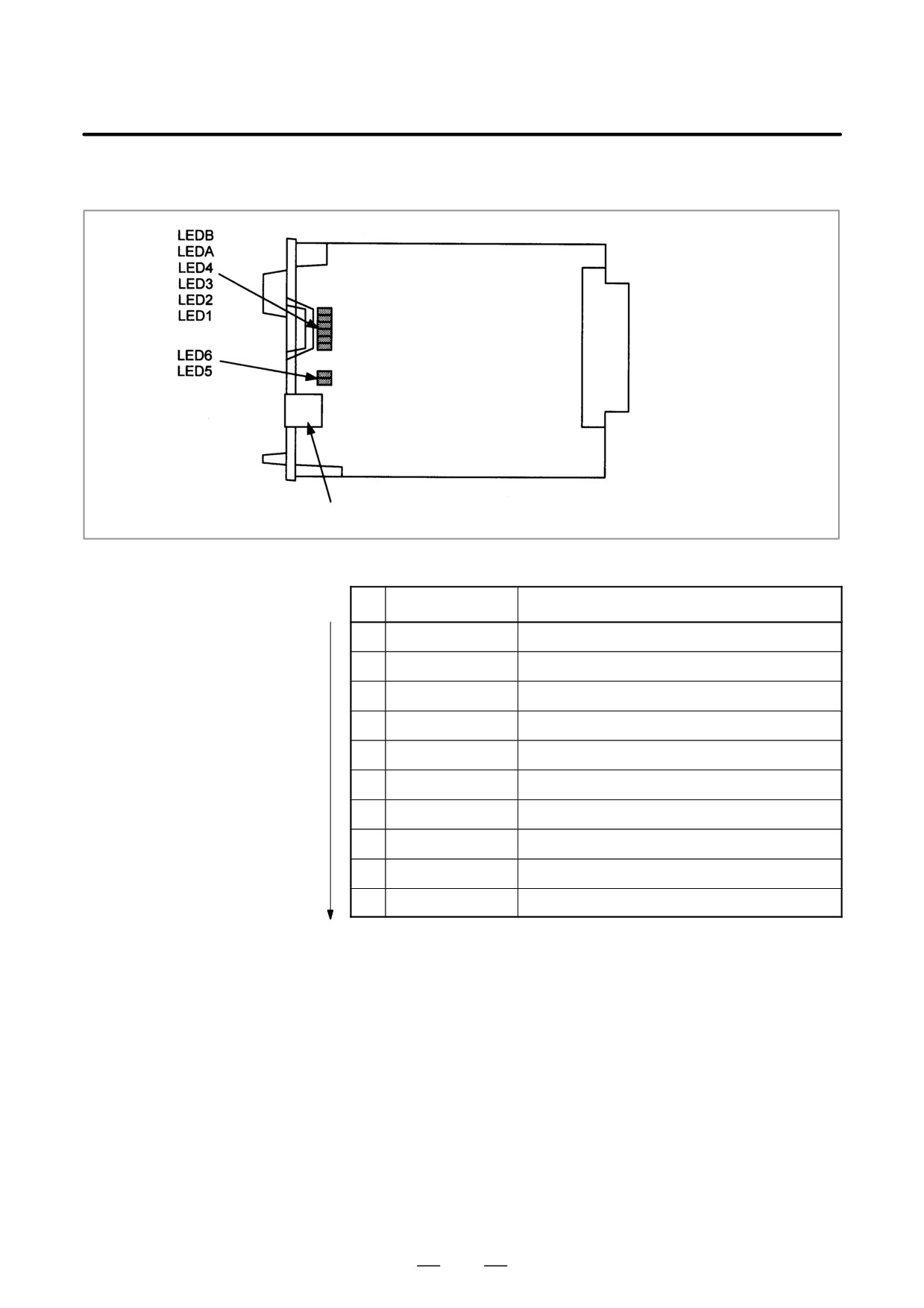
309
4. STAND-ALONE TYPE i SERIES HARDWARE
B-63525EN/02
D Mounting positions of
connectors, LEDs, etc.
JNA
F-BUS backplane
connector
CD38L: Ethernet interface
D LED display
D Status transition at power-up, displayed by the green LEDs
No.
4 3 2 1
Ethernet board status
1
jjjj
Power off
2
JJJJ
Initial state immediately after power-up
3
JJJj
MPU initialization completed
4
JJjj
Firmware downloading completed
5
Jjjj
Control transferred to OS
6
jJJJ
OS PHASE 1
7
jJJj
OS PHASE 2
8
jJjJ
OS PHASE 3
9
jJjj
OS PHASE 4
10
jjjl
Start-up completed
If the board has normally started up, the LEDs display the pattern of
No.10. The LEDs keep this pattern until an error occurs.
310
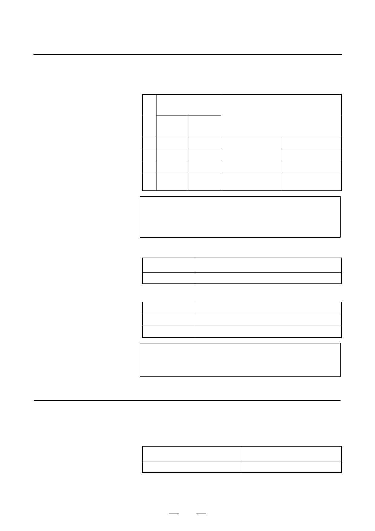
4. STAND-ALONE TYPE i SERIES HARDWARE
B-63525EN/02
D Status LED display when an error occurs (green)
The status LEDs alternately display the LONG and SHORT patterns.
The LONG pattern is held longer than the SHORT pattern.
STATUS LED
indication
No.
Ethernet/data server board state
LONG
SHORT
4321
4321
1
Jjjj
jjjJ
Failure caused by this
System reset
board.
2
Jjjj
jjJj
Machine check
3
JJjj
jjjJ
DRAM parity alarm
4
JJjj
jjJj
Failure caused by anoth-
NMI of another module
er board.
NOTE
If an error, indicated by repeatedly flashing a LONG and
SHORT combination other than the above, occurs, contact
FANUC.
D Alarm LED display (red) when an alarm occurs
State
LEDB
Lit when a parity alarm occurs in the main memory on this board.
D Communication status LED display (red)
LED5 (TX)
Lit when data is sended.
LED6 (RX)
Lit when data is received.
LEDA (COL)
Lit when a data collision occurs.
NOTE
LEDA (COL) is frequently lit if the traffic of Ethernet
communication is large or if the peripheral noise is large.
4.4.10
DeviceNet Board
D Specifications
Item
Code
DeviceNet board
A20B-8100-0491
311
4. STAND-ALONE TYPE i SERIES HARDWARE
B-63525EN/02
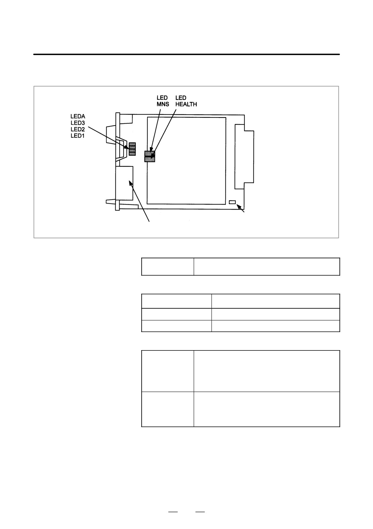
D Mounting positions of
connectors, LEDs, etc.
JNA
F-BUS backplane
connector
Daughter board
(other manufacturer)
TM1
Master/slave setting pin
TBL: DeviceNet interface
D LED display
D Meaning of red LED
LEDA
Lit when an error occurs on the daughter board.
If this LED is lit, replace the DeviceNet board.
D Meanings of green LEDs
3 2 1
Status
jjJ
This board is set as the master.
jJJ
This board is set as the slave.
D LEDs on the daughter board
MNS
DeviceNet module/network status LED
This LED indicates whether the DeviceNet board is turned on
and whether the DeviceNet communication is normally per-
formed.
For the meanings of statuses indicated by this LED, refer to the
specifications supplied by ODVA.
HEALTH
Daughter board status LED
After the board is turned on, the LED is lit in red. If the firmware
is loaded into the internal daughter board, the LED is lit in green.
This green state continues.
If the LED is not lit in green, replace the DeviceNet board.
D Master/slave setting pin
This setting pin is used to switch around the master function and slave
function of DeviceNet.
D Precautions
This DeviceNet board can be removed after the main CPU board is
removed. For the procedure, see “Mounting and Removing an Option
Board.”
A daughter board of a different manufacturer is mounted on the
DeviceNet board. The daughter board alone cannot be replaced.
312
4. STAND-ALONE TYPE i SERIES HARDWARE
B-63525EN/02
4.4.11
PROFIBUS Master
Board
D Specifications
Item
Code
PROFIBUS master board
A20B-8100-0470
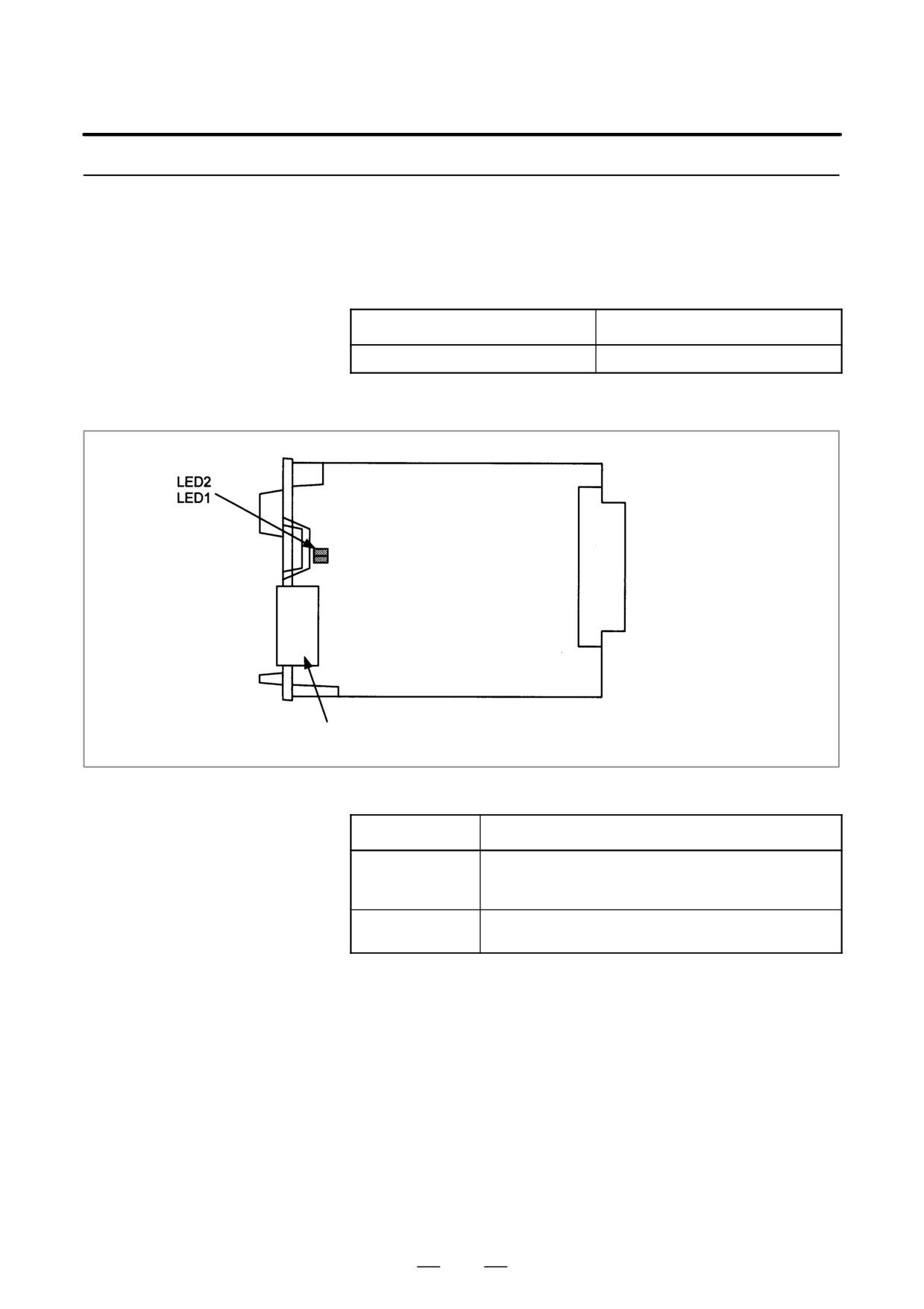
D Mounting positions of
connectors, LEDs, etc.
JNA
F-BUS backplane
connector
CN1: PROFIBUS interface
D LED display
D Status LED display (green)
State
LED1
Lit when this board is released from the reset state and starts
operating.
This LED is not lit at power-up.
LED2
Lit when the communication is normally performed.
This LED is not lit at power-up.
313
4. STAND-ALONE TYPE i SERIES HARDWARE
B-63525EN/02
4.4.12
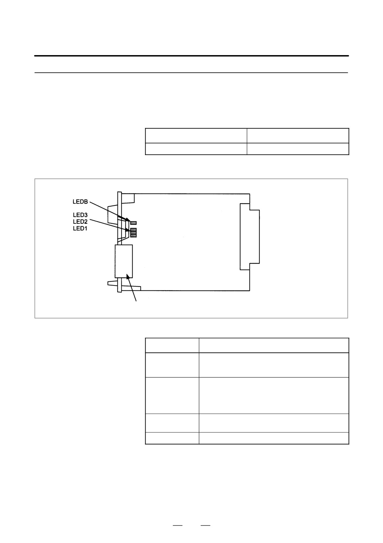
PROFIBUS Slave
Board
D Specifications
Item
Code
PROFIBUS slave board
A20B-8100-0440
D Mounting positions of
connectors, LEDs, etc.
JNA
F-BUS backplane
connector
CN2: PROFIBUS interface
D LED display
D Status LED display (green)
State
LED1
Lit when this board is released from the reset state and starts
operating.
This LED is not lit at power-up.
LED2
Lit when the communication starts.
The LED is not lit at power-up. The LED is not lit also in the
following cases:
· When no parameter configuration data is received
· When illegal parameter configuration data is received
LED3
Lit when the communication is normally performed.
This LED is not lit at power-up.
LEDB
Lit when a RAM parity alarm occurs on this board.
314
4. STAND-ALONE TYPE i SERIES HARDWARE
B-63525EN/02
4.4.13
FL-net Board
D Specifications
Item
Code
FL-net board
A20B-8100-0530
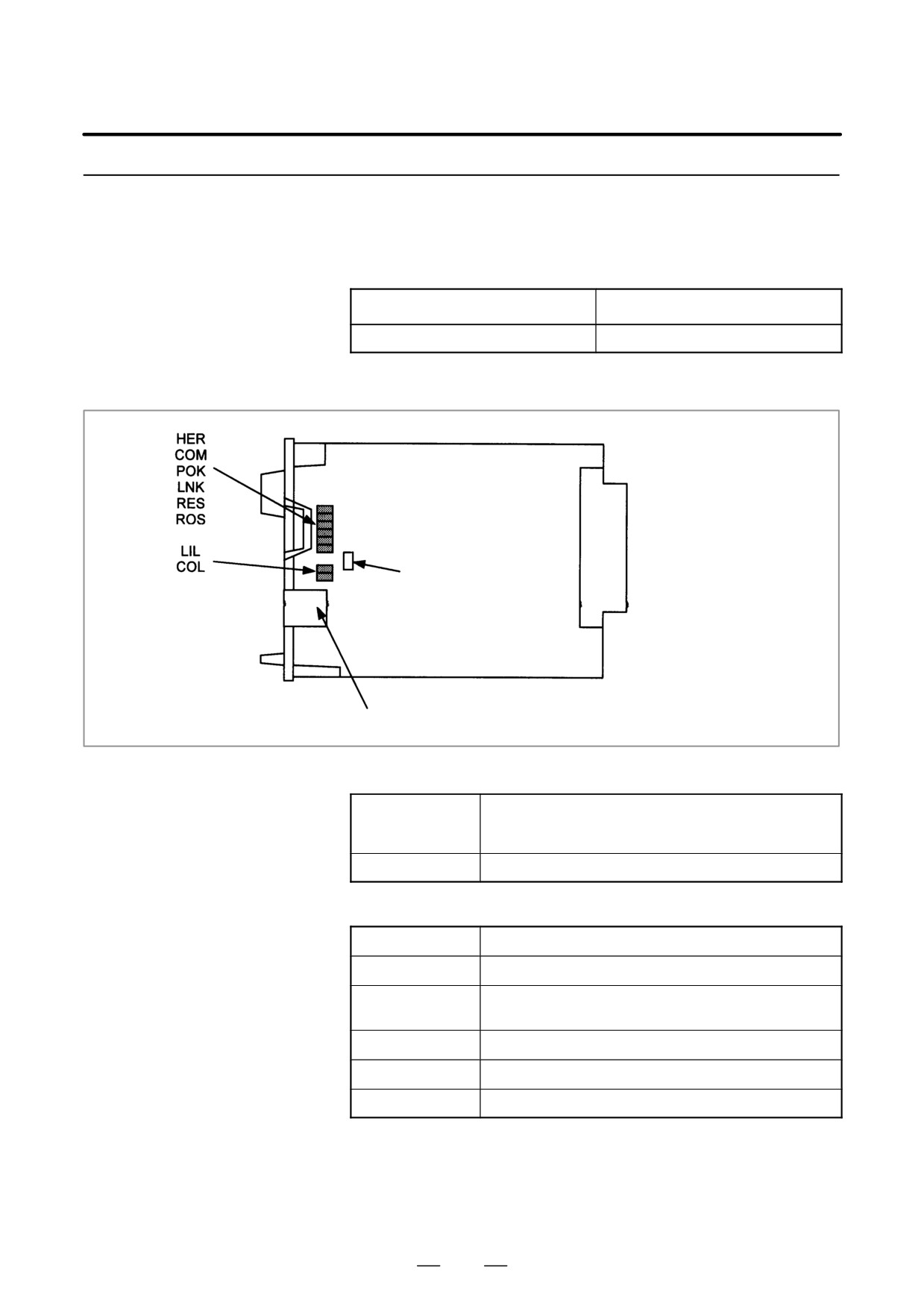
D Mounting positions of
connectors, LEDs, etc.
JNA
F-BUS backplane
connector
Setting pin TM1
(fixed to B)
CD38N: FL-net interface
D LED display
D Meanings of red LEDs
HER
Lit when a parity alarm occurs in the DRAM on the FL-net
board.
The board may be defective.
COL
Lit if a data collision occurs on the line.
D Meanings of green LEDs
COM
Lit during data transmission or reception.
POK
Lit when the parameters are normally set.
LNK
This LED indicates the link state and is lit if the board partici-
pates in the FA link.
RES
Reserved. This LED is normally lit.
ROS
Lit while the OS is running on the FL-net board.
LIL
Lit when a hub is normally connected.
D Setting pin TM1
This setting pin is always set to position B. The setting should not be
changed.
315
4. STAND-ALONE TYPE i SERIES HARDWARE
B-63525EN/02
4.4.14
Main CPU Board of CNC
Display Unit with PC
Functions and PANEL i
D Specifications
Item
Code
Main CPU board
For Windows95
For 10.4”/12.1” LCD
A20B-2100-0690
(For basic unit A08B-0082-B001 to -B004, -B011 to
-B014, -B021 to -B024)
For 15.0” LCD
A20B-2100-0691
For other OS than Windows95
For 10.4”/12.1” LCD
A20B-2100-0692
For 15.0” LCD
A20B-2100-0693
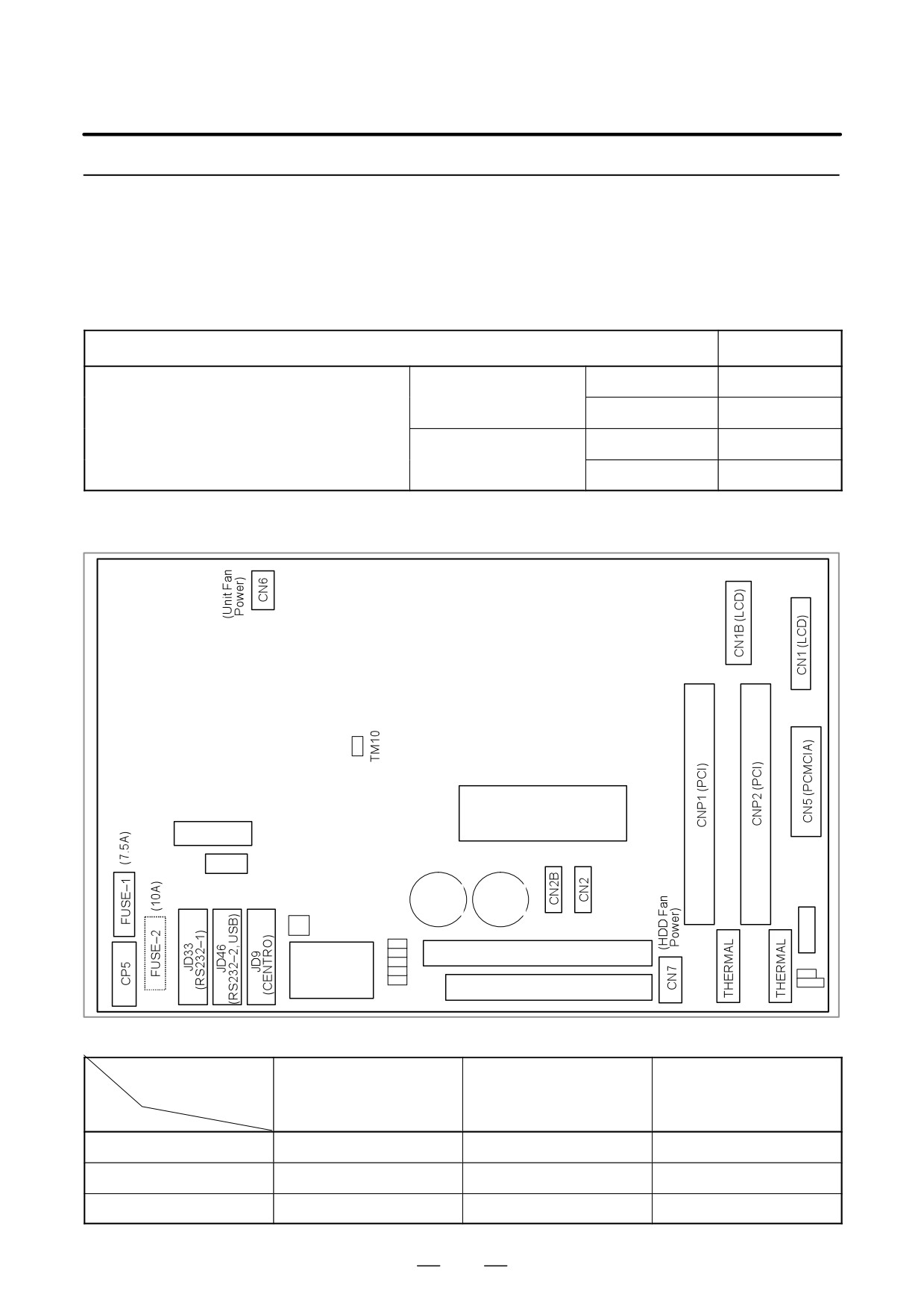
D Mounting positions of
connectors, LEDs, etc.
*4
CN4
(Inverter)
*4
(PC Card)
CN3
*4
(FDD
CD32B
CD32A
Power)
BAT1
MOUSE
Keyboard
BATTERY
(HDD
LED
Power)
CNH3 (HDD signal)
COP7
SW5
(HSSB)
CD34 (FDD signal)
SW7
Mounting positions of the parts in the location indicated by *4
LCD Unit Type
10.4”/12.1”LCD
15.0”LCD
(Code of PC board)
Fuse for maintenance
(A20B-2100-0690, -0692)
(A20B-2100-0691, -0693)
Parts
FUSE-1
Provided
None
A02B-0236-K101
FUSE-2
None
Provided
A08B-0082-K001
CN1B
None
Provided
—
316
4. STAND-ALONE TYPE i SERIES HARDWARE
B-63525EN/02
D Specifications
Item
Code
Main CPU board
For Windows95
For 10.4” LCD
A20B-2100-0780
(For basic unit A08B-0082-B031 to -B038, -B041 to
-B048, -B051 to -B057)
For 12.1” LCD
A20B-2100-0781
(For basic unit A13B-0193- B031 to -B038, -B041 to
-B048, -B051 to -B057)
For 15.0” LCD
A20B-2100-0782
For other OS than Windows95
For 10.4” LCD
A20B-2100-0783
For 12.1” LCD
A20B-2100-0784
For 15.0”LCD
A20B-2100-0785
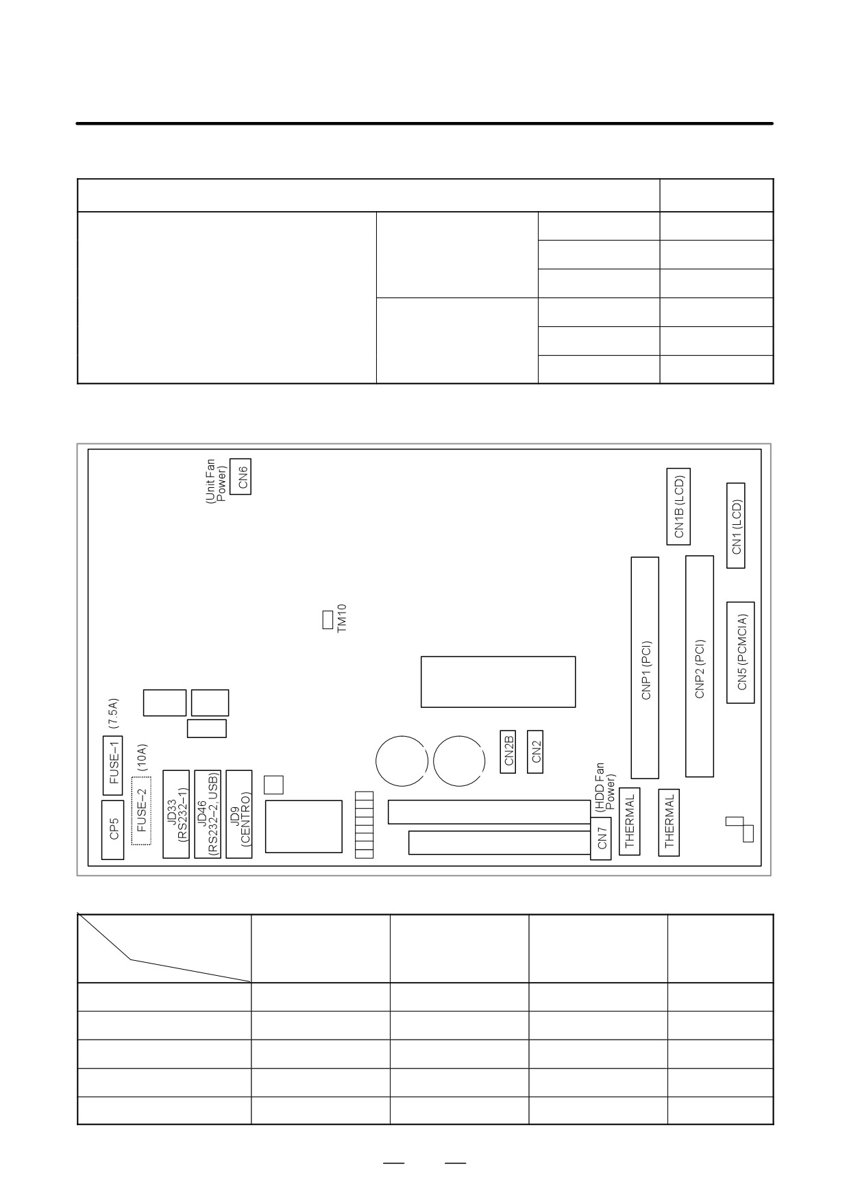
D Mounting positions of
connectors, LEDs, etc.
*5
(Inverter) *5
CN4
(PC Card)
*5
CN3
CN3B
*5
(FDD
CD32B
CD32A
Power)
MOUSE
Keyboard
BAT1
(HDD
BATTERY
LED
Power)
CNH3 (HDD signal)
SW5
COP7
(HSSB)
CD34 (FDD signal)
SW7
Mounting positions of the parts in the location indicated by *5
LCD Unit Type
10.4”LCD
12.1”LCD
15.0”LCD
Fuse for
(Code of PC board)
(A20B-2100-0780,
(A20B-2100-0781,
(A20B-2100-0782,
maintenance
Parts
-0783)
-0784)
-0785)
FUSE-1
Provided
None
None
A02B-0236-K101
FUSE-2
None
Provided
Provided
A08B-0082-K001
CN3
Provided
Provided
Provided
—
CN3B
None
None
Provided
—
CN1B
None
None
Provided
—
317
4. STAND-ALONE TYPE i SERIES HARDWARE
B-63525EN/02
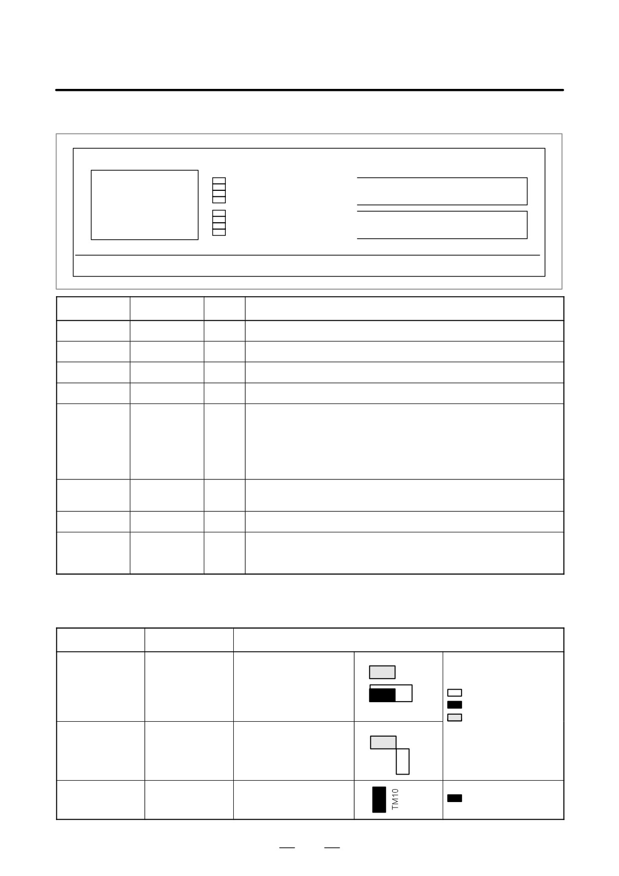
D LED display
GR1(Green)
+5V(Green)
GR2(Green)
HDD(Green)
GR3(Green)
CNC(Green)
CNH3 (HDD Signal)
COP7
GR4(Green)
or
CRD(Green)
RE1(Red)
BUS(Red)
*6
RE2(Red)
BAT (Red)
CD34 (FDD Signal)
RE3(Red)
FAN(Red)
RE4(Red)
TRM(Red)
Name 1(*6)
Name 2(*6)
Color
Status
GR1
+5V
Green
Lights when +5 V is supplied.
GR2
HDD
Green
Lights when the HDD is accessed.
GR3
CNC
Green
Lights when the CNC operates normally.
GR4
CRD
Green
Lights when PCMCIA is accessed.
RE1
BUS
Red
Lights when transfer over the HSSB is interrupted. Possible causes are
shown below.
S The CNC unit is not powered.
S The optical fiber cable is not connected.
S The interface on the CNC side failed.
S The CNC display unit with PC functions or the PANEL i failed.
RE2
BAT
Red
Indicates a battery alarm. Replace the battery installed in the CNC display
unit with PC functions or in the PANEL i.
RE3
FAN
Red
Lights when the basic unit fan or HDD fan stops. Replace the failed fan.
RE4
TRM
Red
Indicates a temperature alarm. This LED lights when the CPU detects a
high temperature that falls outside the use range. (This decreases the
operating speed of the CPU.)
*6:These labels may vary with the drawing number or version number of
the main board.
D Short plug settings
Short plug
Settings
Location
SW5
Reserved
Do not change the factory-set
SW5
SW7
defaults.
(A20B-2100
–0690 to -0693)
: Open
: Short
SW7
: Short (PANEL i)
Open (CNC display
SW5
Reserved
Do not change the factory-set
SW5
unit with PC functions)
TM7
defaults.
(A20B-2100
–0780 to -0785)
TM7
TM10
Reserved
This short plug is provided for
testing purpose.
: Short
Be sure to insert this plug.
318
4. STAND-ALONE TYPE i SERIES HARDWARE
B-63525EN/02
4.4.15
Mother Board of CNC
Item
Code
Display Unit for is
Mother Board of CNC display unit for is series
A20B-8100-0800
Series
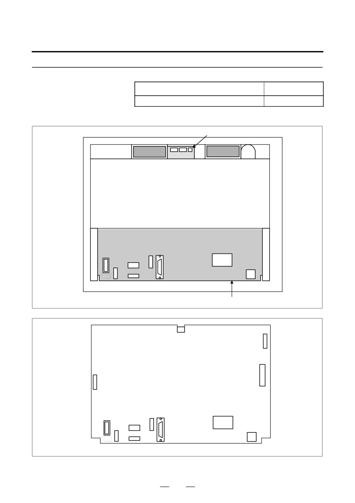
D Mounting positions of
connectors
Connector unit
Fan motor
Fan motor
Rear of unit
JD48
COP7
CP1
CK2
CD38S
CN2
CA75
Motherboard
CN3
CN8
PCMCIA2
Motherboard
TP1
COP7
JD48
CP1
CK2
CD38S
CA75
CN2
319

4. STAND-ALONE TYPE i SERIES HARDWARE
B-63525EN/02
Connector number
Use
JD48
PC side RS232C,USB
COP7
High-speed optical communication(HSSB)
CN2,CK2
Soft key
CP1
DC24V-IN
CD38S
PC side Ethernet(10BASE-T/100BASE-TX)
TP1
Touch panel
CA75
Backup unit
CN8
Video signal interface
PCMCIA2
PCMCIA interface
D Mounting position of
cards
(1) power supply unit
(2) CE card
Connector
Connector
Mother board
No.
Item
Code
Remarks
(1)
CE card
CE card 1
A20B-3300-0330
10.4” color LCD
CE card 2
A20B-3300-0320
(2)
Power supply unit
A20B-8100-0720
NOTE
1
See Section 3.5, ”CE CARD” for the configuration of the CE
card.
2
See Section 3.6.2, ”Installing and Removing the CE Card”
for the installation and removal of the CE card.
320
4. STAND-ALONE TYPE i SERIES HARDWARE
B-63525EN/02
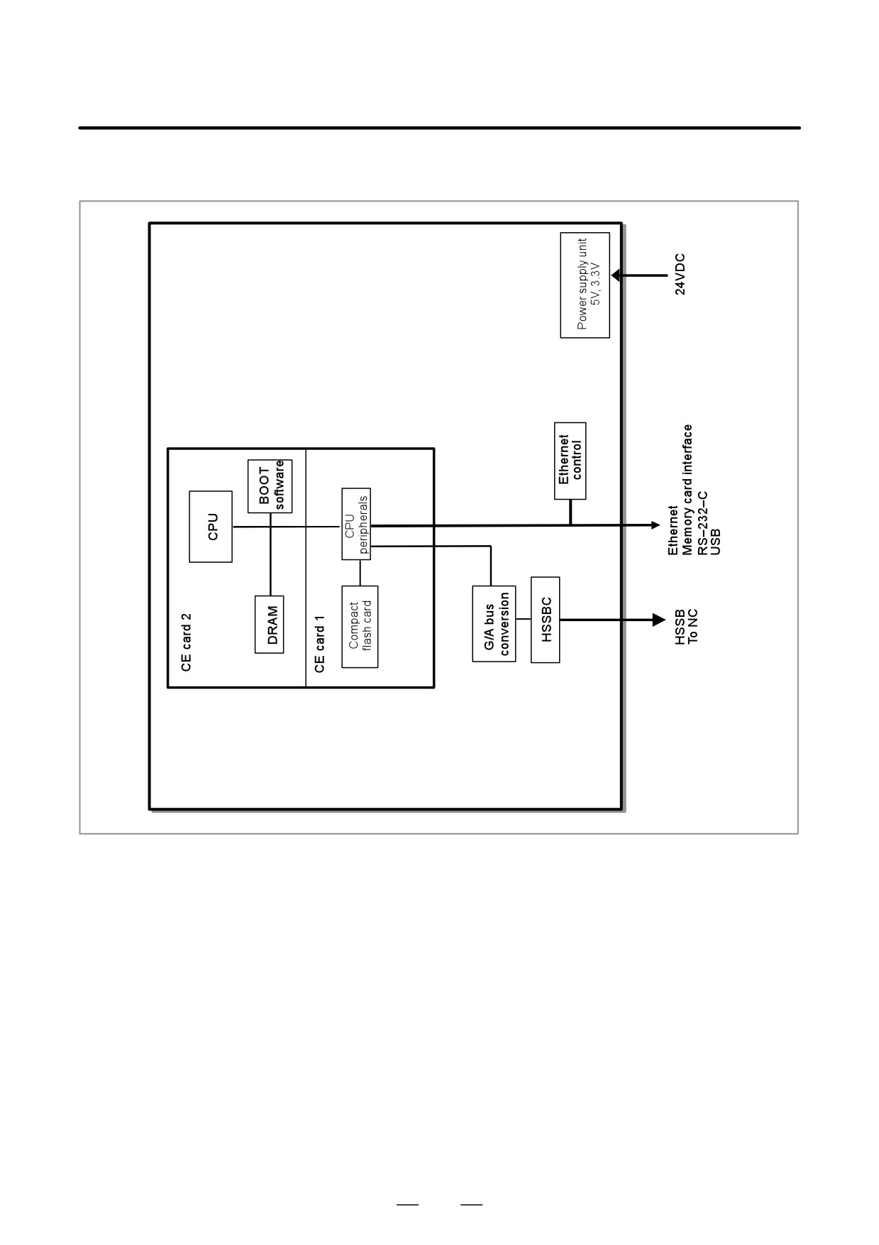
D Block diagram
321
4. STAND-ALONE TYPE i SERIES HARDWARE
B-63525EN/02
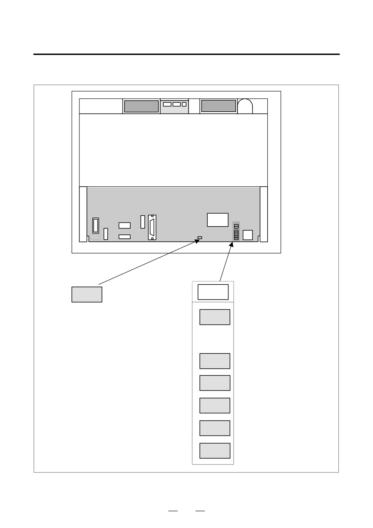
D LED display
Rear of unit
Lights when the unit failed to
Alarm (Red)
LED1
communicate with the NC over
LEDP
the HSSB.
Lights when the CE card is
Lights when the unit communicates
LED2
powered on (including during
with the NC over the HSSB.
backup operation).
Status (Green)
LED3
RESERVE*
Flashes while data is being sent or
LED4
received over the Ethernet on the
PC side.
Lights when a link is established in
LED5
100 Mb/s mode over the Ethernet
on the PC side.
LED6
RESERVE*
LED7
RESERVE*
For some boards, LED3, LED6, and LED7 are not
mounted.
322
4. STAND-ALONE TYPE i SERIES HARDWARE
B-63525EN/02
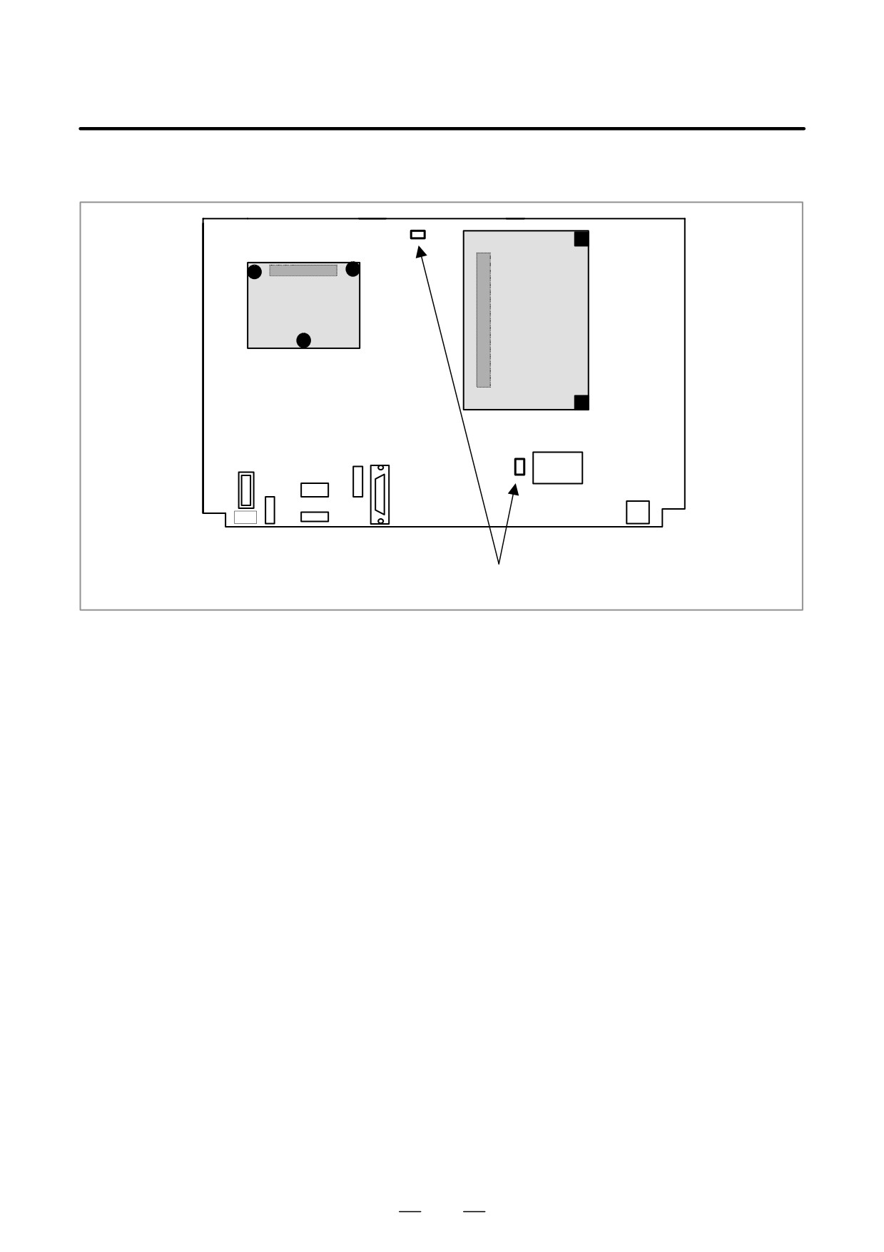
D Short plug settings
Mother board
These short plugs are reserved.
Be sure to remove them.
323
4. STAND-ALONE TYPE i SERIES HARDWARE
B-63525EN/02
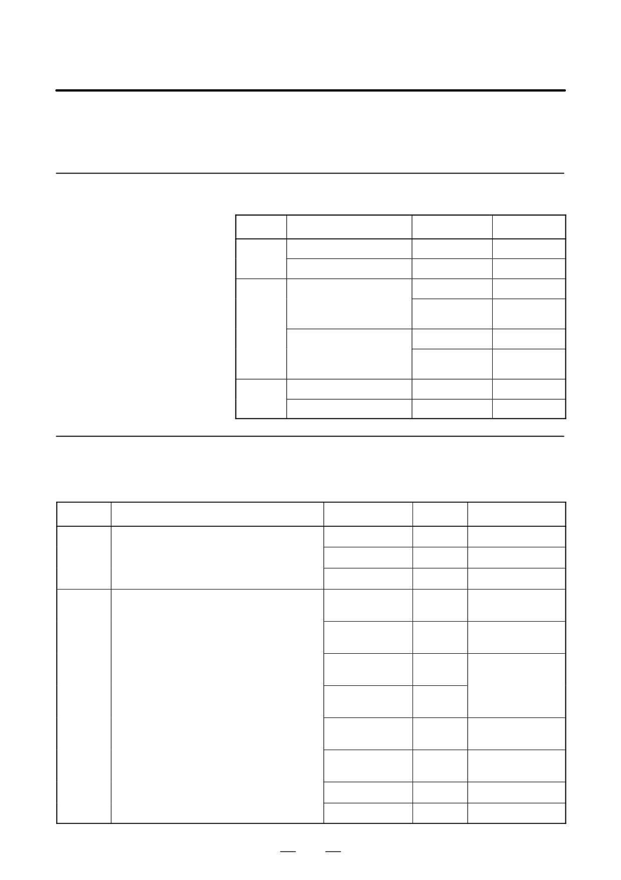
4.5
UNITS AND PRINTED
CIRCUIT BOARDS
4.5.1
Basic Units
Type
Item
Drawing No.
Remarks
16i/160i/
Basic unit with 1 slot
A02B-0281-B801
160is
Basic unit with 3 slots
A02B-0281-B803
18i/180i/
Basic unit with 1 slot
A02B-0283-B801
180is
A02B-0297-B801
For 18i180i/
180is-MB5
Basic unit with 3 slots
A02B-0283-B803
A02B-0297-B803
For 18i/180i/
180is-MB5
21i/210i/
Basic unit with 1 slot
A02B-0285-B801
210is
Basic unit with 3 slots
A02B-0285-B803
4.5.2
Printed Circuit Boards
of Control Unit
Type
Item
Drawing No.
ID
Remarks
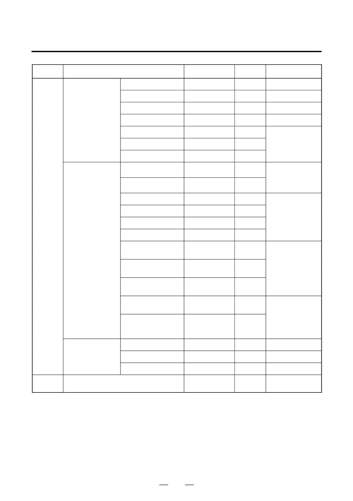
Master
Main CPU board
A16B-3200-0420
3X0C
16i/160i/160is
PCB
A16B-3200-0421
3X0D
18i/180i/180is
A16B-3200-0425
3X0E
21i/210i/210is
Card PCB
CPU card
A20B-3300-0310
CPU: 11
16i/18i/160i/180i/
DRAM: A9
160is/180is
A20B-3300-0311
CPU: 11
16i/18i/160i/180i/
DRAM: AA
160is/180is
A20B-3300-0312
CPU: 11
21i/210i/210is
DRAM: A9
When the embedded
Ethernet is used
A20B-3300-0313
CPU: 11
DRAM: AA
A20B-3300-0290
CPU: 09
21i/210i/210is
DRAM: 8A
A20B-3300-0291
CPU: 09
21i/210i/210is
DRAM: 89
A20B-3300-0102
0A
RISC board
A17B-3300-0400
0A
324
4. STAND-ALONE TYPE i SERIES HARDWARE
B-63525EN/02
Type
Item
Drawing No.
ID
Remarks
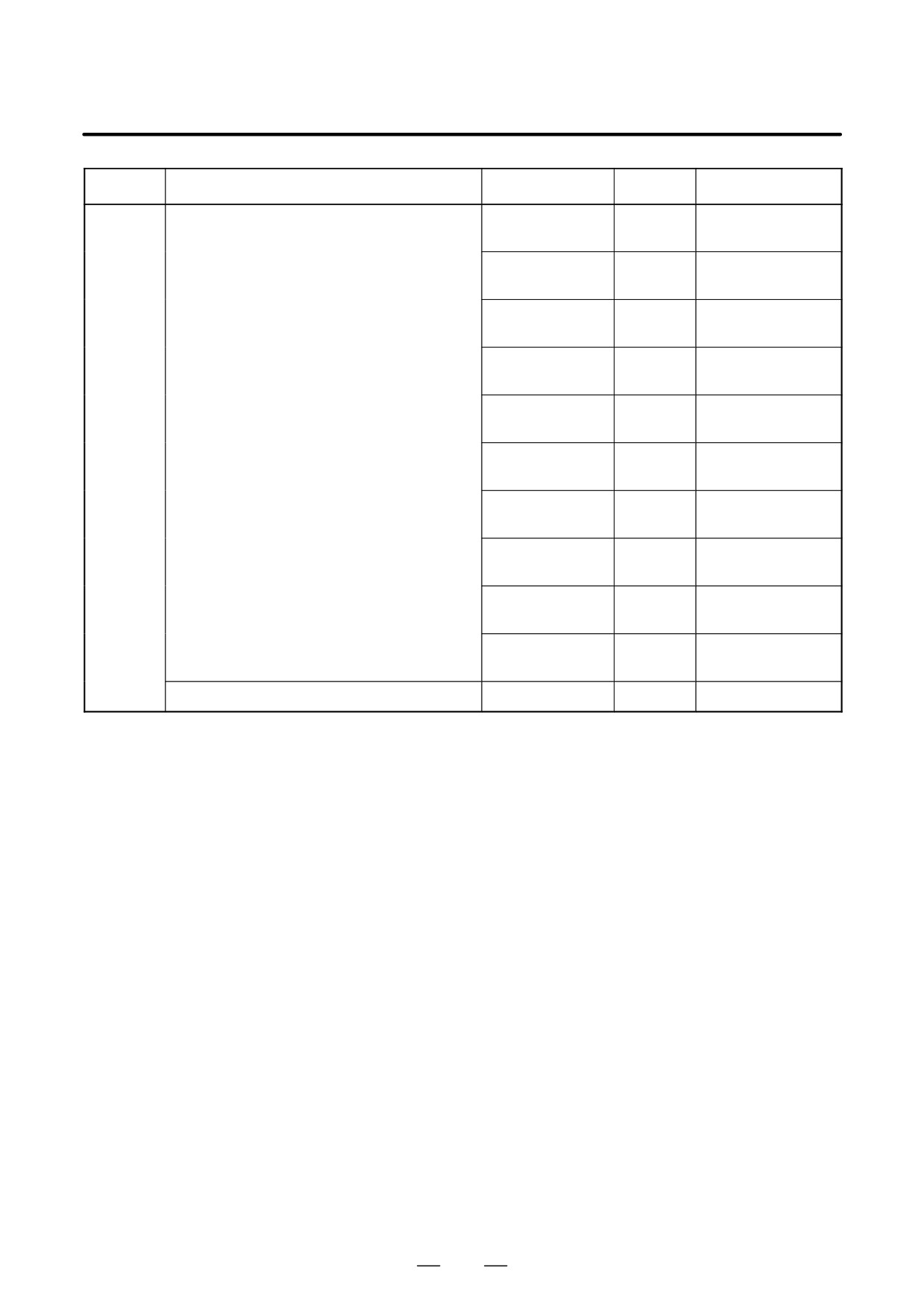
Card PCB
Display control card
LCD/MDI
A20B-3300-0340
-
For CRT LINK
A20B-3300-0360
-
MDI only
A20B-3300-0362
-
No display
A20B-3300-0364
-
LCD/MDI
A20B-3300-0341
-
21i/210i/210is
When the embedded
For CRT LINK
A20B-3300-0361
-
Ethernet is not used
MDI only
A20B-3300-0363
-
Axis control card
2 axes
A20B-3300-0033
00
Servo software
Series 9090, 21i/
210i/210is, Loader
4 axes
A20B-3300-0032
01
control
2 axes
A20B-3300-0243
08
Servo software
Series 90B0
4 axes
A20B-3300-0242
08
6 axes
A20B-3300-0241
08
8 axes
A20B-3300-0240
08
4 axes, High-speed
A20B-3300-0248
08
Servo software
HRV
Series 90B0
6 axes, High-speed
A20B-3300-0245
08
HRV
8 axes, High-speed
A20B-3300-0244
08
HRV
Learning controlled axis
A20B-3300-0246
08
Servo software
control
Series 90B3/90B7
Learning controlled axis
A20B-3300-0247
08
control, High-speed
HRV
Display control card
10.4″ color
A20B-3300-0280
-
Graphic
(LCD unit side)
9.5″ monochrome
A20B-3300-0282
-
Graphic
9.5″ monochrome
A20B-3300-0302
-
Character only
Power
Power supply unit
A02B-8100-0851
-
supply unit
325
4. STAND-ALONE TYPE i SERIES HARDWARE
B-63525EN/02
Type
Item
Drawing No.
ID
Remarks
DIMM
FROM/SRAM module
A20B-3900-0160
FROM: C1
FROM 16MB, SRAM
module
SRAM: 03
1MB
A20B-3900-0161
FROM: C1
FROM 16MB, SRAM
SRAM: 04
2MB
A20B-3900-0162
FROM: C1
FROM 16MB, SRAM
SRAM: 05
3MB
A20B-3900-0163
FROM: C2
FROM 32MB, SRAM
SRAM: 03
1MB
A20B-3900-0164
FROM: C2
FROM 32MB, SRAM
SRAM: 04
2MB
A20B-3900-0165
FROM: C2
FROM 32MB, SRAM
SRAM: 05
3MB
A20B-3900-0180
FROM: C1
FROM 16MB, SRAM
SRAM: 01
256kB
A20B-3900-0181
FROM: C1
FROM 16MB, SRAM
SRAM: 02
512kB
A20B-3900-0182
FROM: C2
FROM 32MB, SRAM
SRAM: 01
256kB
A20B-3900-0183
FROM: C2
FROM 32MB, SRAM
SRAM: 02
512kB
Analog spindle module
A20B-3900-0170
326
4. STAND-ALONE TYPE i SERIES HARDWARE
B-63525EN/02
Type
Item
Drawing No.
ID
Remarks
Option
Sub-CPU board
A16B-2203-0751
1xC0
PCB
Loader control board
A16B-2203-0740
1x97
RISC + data server board
A16B-3200-0390
0x81
3xF5
RISC board
A16B-3200-0391
0x81
Data server board
A16B-3200-0352
3xF5
ATA card adapter
A20B-2100-0500
-
For data server
Serial communication board
A20B-8100-0334
1xE1
(RB/DNC2, CRS232C I/F)
Serial communication board
A20B-8100-0335
2xE1
(RB/DNC2, CRS422 I/F)
Serial communication board (DNC1)
A20B-8100-0336
3xE2
C board
A20B-8100-0330
xxE0
HSSB interface board
A20B-8001-0730
xxAA
Symbol CAPi T board
A20B-8100-0560
xx1F
I/O Link-II board
A20B-8100-0381
xxF9
Ethernet board
A20B-8100-0450
xxE6
DeviceNet board
A20B-8100-0491
xxEF
DeviceNet board C
A20B-8100-0650
PROFIBUS Master board
A20B-8100-0470
xxFC
PROFIBUS Slave board
A20B-8100-0440
xxE3
FL-net board
A20B-8100-0530
xx59
Back
Back panel
A20B-2003-0270
-
1 slot
panel
A20B-2003-0280
-
3 slots
327
4. STAND-ALONE TYPE i SERIES HARDWARE
B-63525EN/02
Type
Item
Drawing No.
ID
Remarks
Distributed
Operator’s panel I/O module
A20B-2002-0470
-
Matrix DI supported
I/O
With MPG interface
A20B-2002-0520
-
General-purpose
DI input
With MPG interface
A20B-2002-0521
-
General-purpose
DI input
Without MPG inter-
face
Connector panel I/O module
Basic
A20B-2100-0150
-
Expansion
A20B-2100-0410
-
With MPG interface
A20B-2100-0411
-
Without MPG inter-
face
A20B-2100-0320
-
DO only
A20B-2100-0190
-
Analog input
Others
LCD control printed circuit board
A20B-8100-0820
-
Inverter
A20B-8001-0920
-
Color
A20B-8100-0710
-
Monochrome
Operator’s panel connection unit
(64/32)
A16B-2200-0661
-
Sink output
(96/64)
A16B-2200-0660
-
Sink output
(64/32)
A16B-2202-0731
-
Source output
(96/64)
A16B-2202-0730
-
Source output
Machine operator’s panel interface unit
A16B-2201-0110
-
Touch panel control board
A20B-8001-0620
-
PCB for separate detector interface unit
A20B-2100-0270
-
HSSB board on the personal computer side
A20B-8001-0583
-
For 1 channel, corre-
sponding to ISA-bus
A20B-8001-0582
-
For 2 channels, cor-
responding to ISA-
bus
A20B-8001-0960
-
For 2 channels, cor-
responding to PCI-
bus
A20B-8001-0961
-
For 1 channel, corre-
sponding to PCI-bus
328
4. STAND-ALONE TYPE i SERIES HARDWARE
B-63525EN/02
4.5.3
LCD/MDI Unit
Item
Drawing No.
Remarks
9.5″ monochrome LCD unit
A02B-0281-C061
9.5″ monochrome LCD unit
A02B-0281-C066
Character only
10.4″ color LCD unit
A02B-0281-C071
10.4″ color LCD unit
A02B-0281-C081
With touch panel
For display link
7.2″ monochrome LCD unit
A02B-0166-C251
7.2″ monochrome LCD/MDI
T series
A02B-0166-C261#TR
Alphabetic keys
unit
A02B-0166-C261#TS
Symbolic keys
M series
A02B-0166-C261#R
Alphabetic keys
A02B-0166-C261#S
Symbolic keys
Detachable
T series
A02B-0166-C271#TR
Alphabetic keys
7.2″
monochrome LCD/MDI
A02B-0166-C271#TS
Symbolic keys
unit
M series
A02B-0166-C271#R
Alphabetic keys
A02B-0166-C271#S
Symbolic keys
Stand-alone type MDI
T series
A02B-0166-C210#TR
Alphabetic keys
A02B-0166-C210#TS
Symbolic keys
M series
A02B-0166-C210#R
Alphabetic keys
A02B-0166-C210#S
Symbolic keys
Stand-alone type MDI standard key
T series
A02B-0281-C125#TBR
Alphabetic keys
(horizontal type)
220x230mm
A02B-0281-C125#TBS
Symbolic keys
M series
A02B-0281-C125#MBR
Alphabetic keys
A02B-0281-C125#MBS
Symbolic keys
Stand-alone type MDI standard key
T series
A02B-0281-C126#TBR
Alphabetic keys
(vertical type)
220x290mm
A02B-0281-C126#TBS
Symbolic keys
T series
A02B-0281-C126#MBR
Alphabetic keys
A02B-0281-C126#MBS
Symbolic keys
61 full-keyboard (horizontal type)
A02B-0261-C162#MCR
Alphabetic keys
220x230mm
A02B-0261-C162#MCS
Symbolic keys
61 full-keyboard (vertical type)
A02B-0261-C161#MCR
Alphabetic keys
220x290mm
A02B-0261-C161#MCS
Symbolic keys
329
4. STAND-ALONE TYPE i SERIES HARDWARE
B-63525EN/02
Item
Drawing No.
Remarks
CAPi T keyboard (horizontal type)
A02B-0281-C125#TFBR
Alphabetic keys
220x230mm
A02B-0281-C125#TFBS
Symbolic keys
CAPi T keyboard (vertical type)
A02B-0281-C126#TFBR
Alphabetic keys
220x290mm
A02B-0281-C126#TFBS
Symbolic keys
4.5.4
Other Units
Item
Drawing No.
Remarks
Separate detector
4 basic axes
A02B-0236-C203
interface unit
4 additional axes
A02B-0236-C204
Connector panel I/O module
Basic module
A03B-0815-C001
Expansion module
A03B-0815-C002
With MPG interface
A03B-0815-C003
Without MPG interface
A03B-0815-C004
2A DO
A03B-0815-C005
Analog input
Distributed I/O machine
Compact type
A02B-0236-C141#xx
DI = 24, with MGP
operator’s panel
interface
Standard type
A02B-0236-C140#xx
DI = 24, with MGP
interface
290-mm wide
A02B-0236-C150#xx
DI = 24, with MGP
interface
Spindle connection adapter
A13B-0180-B001
Fan unit
For 1 slot
A02B-0265-C101
For 2 slots
A02B-0260-C021
330
4. STAND-ALONE TYPE i SERIES HARDWARE
B-63525EN/02
4.5.5
CNC Display Unit with
PC Functions and
PANEL i
Type
Item
Drawing No.
Printed circuit board
Main printed circuit board
For Windows95
For 10.4”/12.1” LCD
A20B-2100-0690
for CNC display unit
(For basic unit A08B-0082-B001 to -B004,
with PC functions and
-B011 to -B014, -B021 to -B024)
For 15.0” LCD
A20B-2100-0691
PANEL i
For OS except for
For 10.4”/12.1” LCD
A20B-2100-0692
Windows95
For 15.0” LCD
A20B-2100-0693
Main printed circuit board
For OS except for
For 10.4”LCD
A20B-2100-0780
(For basic unit A08B-0082-B031 to -B038,
Windows95
–B041 to -B048, -B051 to -B057)
For 12.1”LCD
A20B-2100-0781
(For basic unit A13B-0193- B031 to -B038,
-B041 to -B048, -B051 to -B057)
For 15.0”LCD
A20B-2100-0782
For Windows95
For 10.4”LCD
A20B-2100-0783
For 12.1”LCD
A20B-2100-0784
For 15.0”LCD
A20B-2100-0785
Inverter printed circuit board
For 10.4” LCD
A14L-0132-0001
(For basic unit A08B-0082-B001 to -B004,
-B011 to -B014, -B021 to -B024)
For 12.1” LCD
A20B-2002-0890
For 15.0” LCD
A14L-0143-0002
Inverter printed circuit board
For 10.4” LCD
A14L-0132-0001#B
(For basic unit A08B-0082- B031 to -B038,
-B041 to -B048, -B051 to -B057)
For 12.1” LCD
A14L-0143-0001#B
(For basic unit A13B-0193- B031 to -B038,
-B041 to -B048, -B051 to -B057)
For 15.0” LCD
A14L-0143-0002#B
Soft key printed circuit board
For 10.4” LCD
A86L-0001-0261
For 12.1” LCD
A20B-1007-0760
Printed circuit board for touch panel
A20B-8001-0620
controller
331